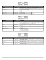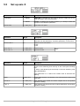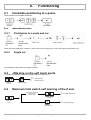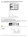
1
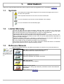
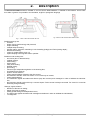
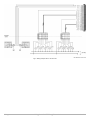
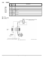
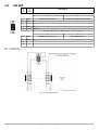
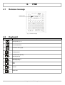
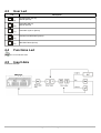
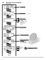
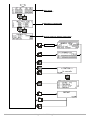
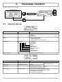
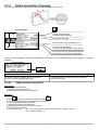
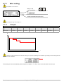
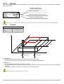
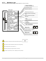
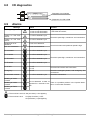
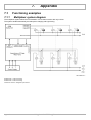
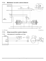
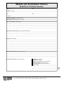
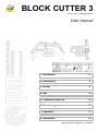
BLOCK CUTTER 3
Block cutter for marble and granite
User manual
1. Information
3
2. Description
5
3. Wiring
6
4. HMI
14
5. Parameter insertion
18
6. Functioning
25
7. Appendix
37
8. Assistance
39
MDU_BLOCKCUTTER03_EN - 04/05/2007
1. Information.....................................................................................................................................3
1.1
1.2
1.3
1.4
Symbols.................................................................................................................................3
Limited Warranty...................................................................................................................3
Reference Manuals...............................................................................................................3
Validity...................................................................................................................................4
2. Description.....................................................................................................................................5
3. Wiring..............................................................................................................................................6
3.1
3.2
3.3
3.4
3.5
Slot 3: H3-I17 card.................................................................................................................7
Slot 4: H3-RV2 card...............................................................................................................9
CNT1....................................................................................................................................11
CNT2....................................................................................................................................12
AN INP.................................................................................................................................13
4. HMI.................................................................................................................................................14
4.1
4.2
4.3
4.4
4.5
4.6
Release message................................................................................................................14
Keyboard..............................................................................................................................14
User Led..............................................................................................................................15
Functions Led .....................................................................................................................15
Insert data............................................................................................................................15
General using example........................................................................................................16
5. Parameter insertion.....................................................................................................................18
5.1
5.2
5.3
5.4
5.5
Generic Set up ....................................................................................................................18
Set up Cutting speed modulation........................................................................................20
Z axis Set up .......................................................................................................................21
Y axis Set up........................................................................................................................22
Set up asse X......................................................................................................................24
6. Functioning...................................................................................................................................25
6.1
6.2
6.3
6.4
6.5
6.6
6.7
6.8
6.9
Immediate positioning to a quota........................................................................................25
Semiautomatic.....................................................................................................................25
JOG stop on the self learnt quota....................................................................................... 25
Maximum limit switch self learning of the Z axis.................................................................25
Cutting speed regulation in function of the disc..................................................................26
Limit switch (Granite cutting)...............................................................................................26
Choice and program working...............................................................................................27
I/O diagnostics.....................................................................................................................36
Alarms .................................................................................................................................36
7. Appendix.......................................................................................................................................37
7.1
Functioning examples..........................................................................................................37
8. Assistance....................................................................................................................................39
8.1
8.2
Service.................................................................................................................................39
Sending................................................................................................................................39
1.
Information
Thanks for buying this QEM instruments. We'll be glad to receive any suggestion at our e-mail address [email protected].
1.1
Symbols
Not reading the message will be dangerous for the instruments integrity and/or for the
success of the operation.
Note: Important information for the correct use of the instruments.
For more informations see the user manual indicated in the message.
For more informations see the indicated pages.
1.2
Limited Warranty
For two (2) years from the original acquisition, QEM will repair or replace for free controls and
devices that QEM thinks be imperfect in materials or quality. This warranty is not valid if the object
has not been tampered by not authorized persons or used in an inappropriate way.
This warranty replaces all other warranties either expressed or implicit.
QEM doesn't hold personally responsible for all charges (installation or uninstalling included), drawback, or damage caused by our products, made or sold. In any case, QEM total duty, always will not
exceed the control total price.
Claims for refunds of selling price, reparations, or replacements must be referred to QEM with all
pertinent data (damage, purchase date, developed work and problem).
It is not provided any duty for batteries and fusible cut-out consumption.
The product must be returned only with a written notification, included the Number of Restitution
Authorization QEM and must be paid all forwarding charges.
1.3
Reference Manuals
You
should
conserve
all
setting
parameters and programming parameters in order to simplify the replacement and the service.
The documentation referred to the QEM instrumentation in divided in many issues that allows an
easy utilization.
MIM - Base: Installation and maintenance manual
Instrument hardware and software information
MIM - Exp: Expansions manual
Expansions hardware and software information.
MDU: User manual
User information on the software.
MIMAT: Service manual
Informations on: wiring, right calibration, parameters insertion and breakdown
individuation.
It is possible to download manuals from www.qem.it
Information
MDU_BLOCKCUTTER03_EN - 04/05/07
3 di 40
1.4
Validity
The present document is fully valid excepted mistakes or omissions.
Manual
Release
1.4.1
Description
Date
1.0
New manual
07/02/05
1.1
Inclined cutting function added
09/06/05
1.2
Manual new version
07/04/06
1.3
New contents
12/04/06
1.4
BLOCKUTTER 3.7 new function added
29/05/06
1.5
BLOCKUTTER 3.9 new function added
29/11/06
1.6
Modify the name of the card at page 7
04/05/07
Trade Marks
The copyright of this user manual is reserved. No one part of this document can be reproduced or
copy without the QEM appointment. QEM doesn't present insurances or warranties on contents and
declines all responsibilities on identity warranties. In this document, informations can be modified
without any notice. QEM doesn't have any responsibility on this document.
Trade Marks:
- QEM® is a trade mark.
Information
MDU_BLOCKCUTTER03_EN - 04/05/07
4 di 40
2.
Description
The BLOCKCUTTER03 software, installed on a micro Qmove D983 hardware, is realized to automatize a "block cutter"
for marble or granite. It is possible to choose italian, english or portoguese language
Fig. 1: Block cutter machine with disc tool
Fig. 2: Block cutter machine with diamond wire
Possible workings are:
– unloader;
– shape copying (self learning) with photocell;
– shape executing;
– multiple shape executing;
– inclined cutting, automatic calculating Y axis forwarding (bridge) and Z axis (cutting depth).;
– diamond wire cutting;
– cutting of multiple blocks (max 10);
– square shaping executing with fresa or polisher.
Possible mode workings are:
– tool choice (disc or diamond wire)
– multiple cuttings;
– settle cutting;
– single cutting;
– many times cutting;
– bilateral cutting;
– pilot cutting;
– "left and right" indipendent regulation of the lowering disc;
– X self-learnt limit switches;
– dynamic X limit switches;
– cutting speed limitation referred to the disc current;
– the instrument handles three axis motion "X-Y-Z" with only an inverter;
– cutting speed settings;
– The instrument signals anomalies with allarms (stop the machine) and messages in order to facilitate the individuation;
– the instrument handle 3 axis with only 2 counters inputs. Z axis counter is always connected. For X and Y it is used an
automatig change handling.
Settings, signals, allarms:
Direction of the last cut setting;
Height of the last cut setting;
Cutting speed settings and indipendent return;
The instrument signals anomalies with messages and allarms in order to facilitate the individuation;
I/O diagnostic.
–
–
–
–
–
Description
MDU_BLOCKCUTTER03_EN - 04/05/07
5 di 40
3.
Wiring
Block cutter 3.9
www.qem.it
Fig. 3: Front view
CNT 1
pin 1
USER port
pin 1
CNT 2
pin 1
SLOT 3
pin 1
SLOT 4
pin 1
SLOT A: Supply
pin 1
PROG port
pin 1
AN INP
pin 1
Fig. 4: Back view
For further information about cut-outs please read the D983 MIM-BASE.
Wiring
MDU_BLOCKCUTTER03_EN - 04/05/07
6 di 40
Activ. modality
Description
Input
Contact
Name
Logic activ. state
Slot 3: L3-I17 card
Clip
3.1
1
+ 12 Vdc -
-
-
-
2
0V
-
-
-
-
3
I0
ON
NO
C
-
Wire stretch mode OK (pag. 34)
4
PL I0
-
-
-
-
Polarizer I0
5
I1
OFF
NC
C
PNP
Forward
6
I2
OFF
NC
C
PNP
Backward
7
I3
OFF
NC
C
PNP
Forward
8
I4
OFF
NC
C
PNP
Backward
9
I5
OFF
NC
C
PNP
Fall
10
I6
OFF
NC
C
PNP
Rise
11
I7
OFF
NC
C
PNP
Automatic accord
12
I8
OFF
NC
C
PNP
Emergency
13
I9
ON
NO
I
PNP
Forward
14
I10
ON
NO
I
PNP
Backward
15
I11
ON
NO
I
PNP
Forward
16
I12
ON
NO
I
PNP
Backward
17
I13
ON
NO
I
PNP
Fall
18
I14
ON
NO
I
PNP
Rise
19
I15
OFF
NC
C
PNP
Unloader out of size (pag. 29)
20
I16
ON
NO
C
PNP
Fast
OFF
NO
C
PNP
Slow
Out 12 Vdc
Limit switch X
Limit switch Y
Limit switch Z
Jog X
Jog Y
Jog Z
Jog Speed selector
I0:
interrupt input
PL I0: I0 interrupt input polarizer
Ix:
digital inputs
Logic activation state:
ON = activated on close contact;
OFF = activated on a open contact.
Activation Modality:
I = pulsing signal;
C= continuous signal.
Contact type:
NC = normally closed;
NO = normally open.
Inputs:
PNP = positive (12-24 V);
NPN / Push-Pull = negative (12-24 V)
Wiring
MDU_BLOCKCUTTER03_EN - 04/05/07
7 di 40
Fig. 5: Wiring example Slot 3: L3-I17 card
Wiring
MDU_BLOCKCUTTER03_EN - 04/05/07
8 di 40
Description
Contact
Name
Logic activ. state
Slot 4: H3-RV2 card
Clip
3.2
1
G AO
-
-
Common AO 1 ÷ AO 2
2
AO 1
-
-
X, Y
3
AO 2
-
-
Z
4
-
-
-
-
5
COM 1
-
-
Common O1 ÷ O8
6
O1
ON
NO
Y
OFF
NO
X
7
O2
ON
NO
Automatic cycle
8
O3
OFF
NC
Allarm Stop (pag. 36)
9
O4
ON /
OFF
NO
Out lubrication
10
O5
ON
NO
End program
11
O6
ON /
OFF
NO
Out alarm (pag. 36)
12
O7
ON
NO
Forward
13
O8
ON
NO
Backward
14
COM 2
-
-
Common O9 ÷ O16
15
O9
ON
NO
Fall
16
O10
ON
NO
Rise
17
O11
ON
NO
X
18
O12
ON
NO
Y
19
O13
ON
NO
Z
20
O14
ON
NO
Out unloader
21
O15
ON
NO
Copying (pag. 31)
22
O16
ON
NO
Slow command X, Y axis
23
COM 2
-
-
Common O9 ÷ O16
Analogic reference axis speed
Axis enable
X/Y
Z
Axis movement
AO x: analogical outputs
G AO: common analogical outputs
Ox:
digital outputs
COM x: common digital outputs
Logic activation state:
ON = activated on close contact;
OFF = activated on a open contact.
Contact type:
NC = normally closed;
NO = normally open.
Wiring
MDU_BLOCKCUTTER03_EN - 04/05/07
9 di 40
Fig. 6: Wiring example Slot 4: H3-RV2 card
Wiring
MDU_BLOCKCUTTER03_EN - 04/05/07
10 di 40
Name
CNT1
Clip
3.3
SCH:
PHA:
PHB:
PHZ:
Description
1
-
-
2
-
-
3
-
-
4
+ 12 Vdc Out 12 Vdc
5
SCH
6
PHA
7
PHB
8
PHZ
9
0V
Shield
Encoder X / Y
shield
Phase A encoder
Phase B encoder
Z encoder
Fig. 7: Wiring example CNT1
Wiring
MDU_BLOCKCUTTER03_EN - 04/05/07
11 di 40
Name
CNT2
Clip
3.4
SCH:
PHA:
PHB:
PHZ:
Description
1
-
-
2
-
-
3
-
-
4
+ 12 Vdc Out 12 Vdc
5
SCH
6
PHA
7
PHB
8
PHZ
Photocell
9
0V
-
Shield
Encoder Z
shield
encoder Phase A
encoder Phase B
Z encoder
Fig. 8: Wiring example CNT2
Wiring
MDU_BLOCKCUTTER03_EN - 04/05/07
12 di 40
Name
AN INP
Clip
3.5
Description
Parameter insertion (set up) – Generic Set up - Lim vel. X (pag.19)
1
AI 1
2
G AI
0V
3
-
-
4
G AI
0V
5
+5V
OUT 5 V
0
1
Speed Forward X axis
Speed Forward/Backward X axis
Parameter insertion (set up) – Generic Set up - Lim vel. X (pag.19)
AI x:
G AI:
6
AI 2
7
G AI
0V
8
-
-
9
-
-
0
1
Speed Backward X axis
Drive blade current
analogical inputs
0V analogical inputs
Fig. 9: Wiring example AN INP
Wiring
MDU_BLOCKCUTTER03_EN - 04/05/07
13 di 40
4.
4.1
HMI
Release message
Software name
Fig. 10: Release message
4.2
Keyboard
Key
Descriptions
Set up axis (pag. 18)
Access data insert
Access to HELP page
(F1)
(F5)
Semiautomatic (led on)
Manual (led off)
(F6)
Automatic (led on)
Manual (led off)
(F7)
Stop
Start
(F8)
(F9)
HMI
I/O diagnostics
Restart
Reset axis
MDU_BLOCKCUTTER03_EN - 04/05/07
14 di 40
4.3
User Led
Led
Description
(F5)
Semiautomatic (led on)
Manual (led off)
(F6)
Automatic (led on)
Manual (led off)
(F7)
(F8)
(F9)
4.4
Automatic Cycle on (led on)
Instrument to RESTART (led on)
RESTART done (led on)
Functions Led
See manual MIM-BASE D983
4.5
Insert data
Insert data example.
HMI
MDU_BLOCKCUTTER03_EN - 04/05/07
15 di 40
4.6
General using example
Principal pages
Principal page
Working check
Visualize informations about the working
Working choice:
- Vertical cutting;
- Horrizontal cutting;
- Copying;
- Slanting disc cutting ;
- Wire cutting ;
- Multiblock saw
- Square.
Working program
Cutting tool parameters
Granite Cutting Specific
Parameters
A = Z axe, Sx increase
B = Z axe, Dx increase
C = Last cutting height
D = Last cutting height direction
Move the
arrow on the
axis quota for
the self
learning
HMI
X,Y axis quota self learning
Necessay self learning quotas for
automatic workings
MDU_BLOCKCUTTER03_EN - 04/05/07
16 di 40
Axis speed
% of X, Y, Z axis
Absorbition / Speed table
Granite cutting to dinamic limit switch
Password: 4624
x 2 sec.
HMI
MDU_BLOCKCUTTER03_EN - 04/05/07
17 di 40
5.
Parameter insertion
In order to enter in the set-up area:
Principal pages
Password: 4624
5.1
Generic Set up
Parameter
Range
Description
Lang.
1,2, 3
1: italian,
2: english,
3: portuguese.
Default
0÷1
To restore default data:
– set this parameter to 0;
– switch off then on the instrument.
Working set
XXXXXX
(Es. 1 0 1 0 1 0 1).
0 = working ok
1 = working off.
Working type:
- Square
- Multiblock saw
- Wire cutting
- Slanting disc cutting
- Copying
- Horizontal cutting
- Vertical cutting
Decimal number
0÷2
Number of decimal numbers.
Parameter
Range
Description
T lubr. ON
0 ÷ 99999.999 (sec.)
Time on
T lubr. OFF
0 ÷ 99999.999 (sec.)
Time off
X encoder
0÷1
0: handled by an encoder
1: not handled by an encoder
T end prog
-99999 ÷ 99999
End of program output activation timer (O5)
< 0: the output remain enabled until a restart
0: activation for one second
> 0: activation for a set time
Parameter insertion
MDU_BLOCKCUTTER03_EN - 04/05/07
Out lubrication (O4)
X axis
18 di 40
Parameter
Range
Description
Z axis movement
0÷2
Z and X axis motion during the incremental cutting
0:X axis moves after the Z axis lowering
1: X axis moves simultaneously with Z axis lowering
2: Z axis begins the lowering when X axis enter the slow-down
X vel. Lim.
0÷1
Automatic limitation X axis speed
0: Off;
1: regulation inversely proportional to the disc motor current
Dynamic LS
0÷1
In order to use this function enable Lim. Vel. X parameter
0: OFF
1: ON
T. esc. block
0 ÷ 99,999
Time between blade exit from the block and the next axis movimentation (with Dynamic LS = 1)
Parameter
Range
Description
Incl. Saw ref.
0÷1
Blade inclination:
0°
0: Inclination with horizontal reference
α
1: Inclination with vertical reference
0°
α
Y reset
0÷1
Reset Y axis at the end of the semi-automatic movement
0: OFF
1: ON
Z encoder
0÷2
0: Z axis management to encoder.
1: Z axis management to time (with parameters “Spazio 1s Z”).
2: Z axis management to limit witch.
Tool
0÷1
0: DISC tool
1: WIRE tool
Parameter insertion
MDU_BLOCKCUTTER03_EN - 04/05/07
19 di 40
Parameter
Range
Description
Wait wire T
0 ÷ 999.999 (sec.)
Axis stop time between two movements in “Wire cutting “
Tens. time
0 ÷ 999.999 (sec.)
Axis stop time for "low wire tension"
Shift Min,
0 ÷ 9999999 (Um)
Minimum movement value to do in "TCtrl" for the encoder
breaking check
Ctrl time
0 ÷ 9999999 (ms)
Time to execute the minimum movement "Min mov." for the encoder breaking check
Parameter
Range
Description
T Inv X
0 ÷ 999.999 (sec.)
Timer with no LS control after X axis movement inversion.
T filter X-
0 ÷ 999.999 (sec.)
Filter time for X axis backward LS (I2)
T filter X+
0 ÷ 999.999 (sec.)
Filter time for X axis forward LS (I1)
Auto Y mode
0÷1
Reset Y axis at the end of the automatic movement
0: OFF
1: ON
5.2
Set up Cutting speed modulation
Parameter
Range
Description
ES I of TA
0 ÷ 999.99
Max power data
ES V of TA
0 ÷ 999.99
Max voltage data
SS V of TA
0 ÷ 999.99
Min voltage data
Parameter
Range
Description
CNMD
0 ÷ 999.99
Motor disc nominal power
NPC
1÷9
Number of turn twisted on Transformer Ammeter
RC time
0 ÷ 32767
(tipico 150 ms)
Higher is this value bigger is the filter on the reading the disc
current (AI 2)
Parameter insertion
MDU_BLOCKCUTTER03_EN - 04/05/07
Transformer Ammeter
20 di 40
5.3
Z axis Set up
Parameter
Range
Description
Z resolution
1 ÷ 999999
MEASURE. It indicates the axis covered space to obtain the set encoder impulses in the Pulse parameter.
1 ÷ 999999
PULSE. It indicates the encoder impulses ( x 4 times) to obtain the
set space in the Measure parameter.
Slow Z
0 ÷ 9999 (Um)
Slow-down axis space.
Parameter
Range
Description
T slow Z
0 ÷ 999 (ms)
Deactivation motion outputs time at the speed changing. To command the axis with teleruptors, set 50 this parameter, if not set zero.
Inertia mode Z
0,1
Validate inertia recalculation
0: OFF
1: ON
Forw. iner. Z
0 ÷ 9999 (Um)
Forward inertia
Back iner. Z
0 ÷ 9999 (Um)
Backward inertia
Parameter
Range
Description
Oltrpos. Z
0 ÷ 9999 (Um)
If "recovering play clearance" is not zero, the axis continues his movement over target-quota for a value equal to the set value. It inverts
the movements and positions on a target quota.
Z toler.
+ 999.9 (Um)
Space within the axis is in tolerance. Out of this space an alarm is not
generated
Z max. tol.
+ 999.9 (Um)
Space within the axis is in tolerance. Out of this space an alarm is not
generated
Back lash mode Z
0, 1, 2
0: without recovery play,
1: Forward recovery play,
2: Backward recovery play.
Parameter insertion
MDU_BLOCKCUTTER03_EN - 04/05/07
Z axis
21 di 40
Parameter
Range
Description
Reasc. Dis. IP
0÷1
Disable the axis rising at the beginning of the working
0: re-rise to “0”
1: not re-rise to “0”
No raise Z
0÷1
Disable the axis rising at the end of the working
0: re-rise to “0”
1: not re-rise to “0”
T dis. Z
0 ÷ 9999 (sec.)
Time between axis stop and motion outputs deactivation and position
transducer reading
1s Z shift
0 ÷ 999999 (Um) Space covered in a second
It is used when "Encoder Z"=1
It allows to estimate the activation time of the last "Lowering Z axis"
(O9)
Parameter
Range
Z reascent
0 ÷ 999999 (Um) Rising space Z axis after the marble cutting and before the Y axis
movement.
Inv T Z
0 ÷ 9999.99
5.4
Description
Minimum time between Z axis movement in a direction and the next
in the opposite direction.
Y axis Set up
Parameter
Range
Description
Y resolution
1 ÷ 999999
MEASURE. It indicates the axis covered space to obtain the set encoder impulses in the Pulse parameter.
1 ÷ 999999
PULSE. It indicates the encoder impulses ( x 4 times) to obtain the
set space in the Measure parameter.
0 ÷ 9999 (Um)
Slow-down axis space.
Slow Y
Parameter insertion
MDU_BLOCKCUTTER03_EN - 04/05/07
22 di 40
Parameter
Range
Description
T slow Y
0 ÷ 999 (ms)
Deactivation motion outputs time at the speed changing. To command the axis with teleruptors, set 50 this parameter, if not set zero.
Inertia mode Y
0,1
Validate inertia recalculation
0: OFF
1: ON
Forw. Iner. Y
0 ÷ 9999 (Um)
Forward inertia
Back iner. Y
0 ÷ 9999 (Um)
Backward inertia
Parameter
Range
Description
Overpos. Y
0 ÷ 9999 (Um)
If "recovering play clearance" is not zero, the axis continues his movement over target-quota for a value equal to the set value. It inverts
the movements and positions on a target quota.
Y toler.
+ 999.9 (Um)
Space within the axis is in tolerance. Out of this space an alarm is not
generated
Y max. tol.
+ 999.9 (Um)
Space within the axis is in tolerance. Out of this space an alarm is not
generated
Blacklash mode Y
0, 1, 2
0: without recovery play,
1: Forward recovery play,
2: Backward recovery play.
Parameter
Range
Description
Inv T Y
0 ÷ 999.99 (sec.) Minimum time between Y axis movement in a direction and the next
in the opposite direction.
T enab. Y
0 ÷ 9999 (ms)
Time between axis enable and motion outputs are on and position
transducer reading.
T dis. Y
0 ÷ 9999 (ms)
Time between axis stop and motion outputs deactivation and position
transducer reading
Parameter insertion
MDU_BLOCKCUTTER03_EN - 04/05/07
Y axis
23 di 40
5.5
Set up axis X
Parameter
Range
Description
X resolution
1 ÷ 999999
MEASURE. It indicates the axis covered space to obtain the set encoder impulses in the Pulse parameter.
1 ÷ 999999
PULSE. It indicates the encoder impulses ( x 4 times) to obtain the
set space in the Measure parameter.
X slow-down
0 ÷ 9999 (Um)
Slow-down axis space.
Parameter
Range
Description
T slow X
0 ÷ 999 (ms)
Deactivation motion outputs time at the speed changing. To command the axis with teleruptors, set 50 this parameter, if not set zero.
Inertia mode X
0,1
Validate inertia recalculation
0: OFF
1: ON
Forw. Iner. X
0 ÷ 9999 (Um)
Forward inertia
Back. iners. X
0 ÷ 9999 (Um)
Backward inertia
Parameter
Range
Description
MovMan X
0÷1
X axis manual moviment.
0: start on the advancing face and stop on the JOG inputs retreating
face
1: Start on the advancing face and stop on the next advancing JOG
input (SET/RESET)
Xaxis
If this parameter is =1 it will be set a 500ms timer to avoid the axis
starting
X tiler.
+ 999.9 (Um)
Space within the axis is in tolerance. Out of this space an alarm is not
generated
T enab. X
0 ÷ 9999 (ms)
Time between axis enable and motion outputs are on and position
transducer reading.
T dis. X
0 ÷ 9999 (ms)
Time between axis stop and motion outputs deactivation and position
transducer reading
Parameter insertion
MDU_BLOCKCUTTER03_EN - 04/05/07
24 di 40
6.
6.1
Functioning
Immediate positioning to a quota.
Quota insertion for immediate positioning
6.2
6.2.1
Semiautomatic
Positioning to a quota and cut
At the end of the positioning, cut starts. X axis move on the forward LS (I1), then come back to backward LS (I2).
6.2.2
Single cut
On activating I9 (Jog forward X) a single cut starts.
6.3
JOG stop on the self learnt quota
To enable or to disable virtual limit switches follow the instructions:
XA= enable function
X = disable function
Selec the
X axis
6.4
Enable / Disable
Maximum limit switch self learning of the Z axis
Bring Z axis in JOG on
the maximum
position I3,I4.
+
ZS= enable Limit switch
Self-learning
position
Selec the
Z axis
Z= disable Limit switch
disable
Z Limit switch
Functioning
MDU_BLOCKCUTTER03_EN - 04/05/07
25 di 40
6.5
Cutting speed regulation in function of the disc.
Setting table fort cutting speed (% data) in function of the disc motor current (% data).
Principal pages
Enable to Set up “Lim. Vel X = 1” (pag. 19)
Insert the value on Set up “Limit cutting speed” (pag. 20)
6.6
Limit switch (Granite cutting)
The dynamic limit switches are virtual limit switches that the instrument calculate in function of the disc motor current.
When the blade exits from the block, the current decreases, in that moment will be added a space before execute a lowering movement of the Z axis and then reversing the X axis in order to have another cut.
The calculation is done respecting cutting parameters:
Principal pages
To enable dynamic limit switches it is necessary to set to 1 parameters "Kim. speed X" and "Dynamic Limit switches". (see on Generic set up
pag.18).
(1)
(2)
(3)
(4)
Driving absorption
Control line
Vacuum absorption
length cutting
Functioning
MDU_BLOCKCUTTER03_EN - 04/05/07
26 di 40
6.7
Choice and program working
6.7.1
Vertical cutting
(1÷5)
0: single cutting (marble),
1: multiple cutting (granite).
Blade depth (Um)
Principal pages
Cutting depth (Um)
Cutting depth pilot (Um)
Left increment of the block for
the pilot cutting (Um)
Right increment of the block for
the pilot cutiing (Um)
0: stop
1: forward to FC max.,
2: behind to FC min.
0: forward
1: behind
0: one cutting direction
1: twice cutting direction.
Step (1÷ 5)
after / precedent:
Pieces number (0 ÷ 30000)
Pices width (Um)
At the end of each cut, it is activated OUT unloader (O14) that will be activated until the intervention of the Unloader out of
the working area input (I15).
Limit switches positions self-learning, before X axis working starting
In order to insert the end of program, digit "pieces number = 0"
Before the starting, the X axis has to be on the left of the block (in is necessary that the minimum limit switch is pushed)
In order to disable the pilot cutting, it is necessary put to 0 the "pilot cutting depth" parameter.
Functioning
MDU_BLOCKCUTTER03_EN - 04/05/07
27 di 40
6.7.1.1
Example
Vertical cutting
Step number
1
2
3
Pieces number
2
3
0
20.0mm
8.0mm
0
Width
Disk Trajectory
Tag.
Bil.
(0:@
1:@$)
0
1
1 = Going/Return blade
2 = Cutting width
3 = Marble / Granite
Functioning
MDU_BLOCKCUTTER03_EN - 04/05/07
28 di 40
6.7.2
Horizontal cutting
(1÷5)
0: single cutting (marble),
1: multiple cutting (granite).
Principal pages
Blade depth (Um)
Cutting depth (Um)
0: forward
1: behind
0: one cutting direction
1: twice cutting direction.
Step (1÷ 5)
after / precedent:
Pieces number (0 ÷ 30000)
Pices width (Um)
At the end of each cut, it is activated OUT unloader (O14) that will be activated until the intervention of the Unloader out of
the working area input (I15).
Limit switches positions self-learning, before X axis working starting
In order to insert the end of program, digit "pieces number = 0"
Before the starting, the X axis has to be on the left of the block (in is necessary that the minimum limit switch is pushed)
6.7.2.1
Example
Horizontal cutting
Step number
1
2
Pieces number
3
0
20.0mm
0
Width
Functioning
MDU_BLOCKCUTTER03_EN - 04/05/07
29 di 40
6.7.3
Slanting disc cutting
(1÷5)
Blade depth (Um)
0: stop
1: forward to FC max.,
2: behind to FC min.
Principal pages
Slanting disc (Type of Slanting disc
see to
“Rifer. Slant. blade”)
0: quota on vertical axis
1: depth slanting disc cutting
0: parallel distance cutting
1: horizontal distance cutting
Depth cutting (Um)
Step (1÷ 5)
after / precedent:
Pieces number (0÷30000)
Pieces width (Um)
Limit switches positions self-learning, before X axis working starting
In order to insert the end of program, digit "pieces number = 0"
Before the starting, the X axis has to be on the left of the block (in is necessary that the minimum limit switch is pushed)
Depth
0
type
Thickness
1
0
type
1
De
pth
Depth
Width
Wi
dth
Functioning
MDU_BLOCKCUTTER03_EN - 04/05/07
30 di 40
6.7.4
Shape acquisition (Copying)
This procedure allows to acquire a shape with a photocell installed on the Z axis.
Principal pages
0: single cutting (marble),
1: multiple cutting (granite).
Y axis quota shift (Um)
Z axis rise after every acquisition (Um)
0: From left to right cutting,
1: From left to right and left to right cutting.
0: Z axis not rise to “0” when the cutting end
1: Z axis rise to “0” when the cutting end
At the end of the acquisition, quotas are normalized to a minimum zero value and all the other values positive. The display
visualize:
Principal pages
Conditions of correct acquiring ending
-Z axis limit switch occupation during the descent
- STOP command and RESTART after
6.7.4.1
Conditions of not correct acquiring ending
- Y axis limit switch occupation during to forwarding
- 1000 points are end.
Shape self-learning (COPY)
Preparation
1) Set copying parameters;
2) Put X axis on out obstruction;
3) Position the photocell up on the shape;
Executing
4) Pull
(Led ON = automatic) and after START
;
5) The Z axis goes down moving the photocell downward;
6) The photocell intercepting the shape;
7) Acquisition counter to shape survey;
8) Stand out than Z axis and “Delta Z ris.” quota;
9) Y axis shift of to “Delta Y”;
10) If the photocell is:
ON =The Z axis goes up until the photocell OFF, restart to point n. 5;
OFF = restart to point n. 5.
Functioning
MDU_BLOCKCUTTER03_EN - 04/05/07
31 di 40
6.7.1.1
Executing (CUT)
In order to start the working the operator has to reset the Z axis on the block upper face and put in in execution the self
learned
Preparation
1) Put, on manual mode, X axis to Left of bloc;
Executing
2) Pull
(Led ON = automatic) and after
;
3) The Z axis goes to the sample depth ( or executes the passes cutting up to the sample depth);
4) Execute the cutting to the acquired quota;
5) Stand out than Z axis to “0” if “En. ris. Z” = 1 (pag. 31);
6) Y axis shift;
7) Cycle repetition to point n.3.
6.7.1.1
Immediate cut (COPY & CUT)
In order to start the working the operator has to reset the Z axis on the block upper face and put in in execution the self
learned
Preparation
1) Put, on manual mode, X axis to Left of bloc;
Executing
2) Pull
(Led ON = automatic) and after
;
3) The Z axis goes down moving the photocell downward;
4) The photocell intercepting the shape;
5) Acquisition counter to shape survey and STOP to Z axis;
6) Re-positioning Z axis on the acquired quota;
7) Execute the cutting;
8) Stand out than Z axis to “0” if “En. ris. Z” = 1 (pag. 31);
9) Y axis shift;
10) Cycle repetition to point n.3.
Functioning
MDU_BLOCKCUTTER03_EN - 04/05/07
32 di 40
6.7.1
Wire cutting
The parameter “Tool” must be 1.
Step (1÷ 30)
after / precedent:
0: Y axis move;
1: Z axis move.
Shift incremental axis quota (Um)
To end program digit “ Steo lenght = 0”.
6.7.1.1
Example
Wire cutting
Step number
Axis
Step Length
1
2
3
4
5
6
7
8
0
1
0
1
0
1
0
0
40.0mm
20.0mm
40.0mm
20.0mm
40.0mm
20.0mm
180.0mm
0
Z
Y
If the wire is under a least tension for the block working (I0 = 0) the axis positioning or the automatic cycle starting is blocked and appears the
signal on the main visualization:
The working re-starts automatically after setup timer expiration "T in Tens" from the re-activation of the I0 input.
Functioning
MDU_BLOCKCUTTER03_EN - 04/05/07
33 di 40
6.7.2
Square
This working allows to execute a four-sided figure in the XY plane between the two LS of the X axis and an incremental
quota of the Y axis.
0: single cutting (marble),
1: multiple cutting (granite).
Depth cutting (Um)
Shift incremental Y axis quota (Um)
Number of repetitions square
If the "Deepn. saw" parameter = 0, the automatic cycle, in the marble working, doesn't execute the axis moving to the program beginning.
6.7.2.1
Example
Square
Deepn. saw
50.0 mm
Side
10.0 mm
Repetitions
10
Y
Z
10.0
mm
X
FC SX (I2)
FC DX (I1)
If M/GR(0/1) = 0:
– The Z axis goes down to the 50.0 mm quota or up to the limit switch (I5);
– the X and Y axis perform so many squares how many the repetitions are "Repetition"
If M/GR(0/1) = 1:
– the X and Y axis execute a first square with a 0 depth;
– The Z axis executes a movement equal to the incremental left pass cutting and subsequently the X and the Y execute
a square;
– The cycle is repeated up the 50.0 mm quota or up to the limit switch (I5).
The working starting to the right limit switch of X axis (I2).
Functioning
MDU_BLOCKCUTTER03_EN - 04/05/07
34 di 40
6.7.3
Multiblock saw
This working allows to execute multiple cutting programs on a max of 10 blocs.
0: single cut (marble),
1: multiple cutting (granite).
Thickness disc (Um)
Deepness saw (Um)
Main pages
Deepness pilot saw (Um)
Left increment for the pilot saw
(Um)
Right increment for the pilot
saw (Um)
0: stop
1: FW up to max LS,
2: BW up to min LS.
0: forward
1: backward
0: saw in one direction;
1: saw in each direction.
Bloc (1÷ 10)
after/previous:
Pieces number (0 ÷ 30000)
Width piece (Um)
Bloc (1÷ 10)
after/previous:
Start bloc quota (Um)
It's possible to self-learn the START BLOC QUOTA by pressing
Limit switches positions self-learning, before X axis working starting
To end program insert “ Piece number = 0”.
The working starting to the right limit switch of X axis (I2)
To disable Pilot Saw insert 0 in the “Deepness pilot saw" parameter.
Functioning
MDU_BLOCKCUTTER03_EN - 04/05/07
35 di 40
6.8
I/O diagnostics
Diagnostic from I1 to I16
Diagnostic from O1 to O16
6.9
Alarms
Message
Motive
Solution
End copy /Copy error
- End memory
- Y axis on max limit switch.
- Y axis on max limit switch.
- Upper the step of limit switches in use.
- Check the limit switch;
Cutting on max limit
switch
I1 = off on automatic cycle
Cutting on min limit
switch
I2 = off on automatic cycle
Bridge axis out of
tolerance.
Y axis out of tolerance.
Disc out of tolerance.
Z axis out of tolerance.
FC Y forward
I3 = off on automatic cycle
FC Y behind
I4 = off on automatic cycle
FC Z forward
I5 = off on automatic cycle
FC Z behind
I6 = off on automatic cycle
FC X fault
I1 = off
I2 = off
Emergency
I8 = off
Check the emergency button, and emergency line
connections.
No automatic consent
I7 = off on automatic cycle
Check the connections.
Check the quota digit , transducer and connections.
Check lock sistem and positioner speed is high.
Check the quota digit , transducer and connections.
Check the limit switch and connections.
Breaking of X axis
encoder
Breaking of Y axis
encoder
Are not detected at least 10
There is a possible problem in the impulse detecimpulsed in 2 seconds of motion or in the motion activation.
tion
Breaking of Z axis
encoder
= The machine is not lock: O6 (out alarm) = slow lightning.
= The machine is lock:
Functioning
O3 (Stop for alarm) = OFF,
O6 (Out alarm) = rapid lightning.
MDU_BLOCKCUTTER03_EN - 04/05/07
36 di 40
7.
7.1
7.1.1
Appendix
Functioning examples
Multiplexer system diagram
The multiplexer system allows the movimentation of more than one axis with only a driver.
The system handles automatically the teleruptors changing with right timing.
Enable AXIS 1: brake unblocking
Enable AXIS 2: brake unblocking
Enable AXIS 3: brake unblocking
OUTPUTS common: analogical inputs common
Appendix
MDU_BLOCKCUTTER03_EN - 04/05/07
37 di 40
7.1.2
Multiplexer encoder system diagram
7.1.3
Shape acquisition system diagram
7.1.3.1
Appendix
If the photocell is installation on Z axis
MDU_BLOCKCUTTER03_EN - 04/05/07
38 di 40
8.
8.1
Assistance
Service
In order to provide a quick service, we need your help.
a)
a) Follow all MIMAT indications (www.qem.it)
8.2
b)
b) If the problem persist, compile the fax inserted in the MIMAT manual and send to QEM.
c)
c) Our technicians will obtain necessary elements for understanding your problem.
Sending
It is recommended to pack properly the instrumentation.
a)
a) Use the original pack
b)
b) Enclose:
- A problem description;
-The part of the electric diagram where
the instrument is inserted.
-Instrument programming (set-up,
working quotas, parameters...).
- Request a reparation estimate; if
not request, it will be calculated at
the end.
c)
c) An exhaustive description of the problem
allows a quick individuation and resolution
of the problem.
A good pack will take care of your instrument.
Motivation
QEM informs the customers that instrumentation delivered not properly packed won't be repaired, except in case that the
customer takes all the service responsibilities.
Assistance
MDU_BLOCKCUTTER03_EN - 04/05/07
39 di 40
Modulo per Assistenza Tecnica
Module for Technical Service
Ditta / Firm :...............................................................
Rif.:.............................................................................
Indirizzo / Address:...............................................................................................................................................
...........................................................................................................................................................................
Tel..............................................................................
Fax..............................................................................
E – mail..............................................................................................................................................................
Codice strumento / Instrument Code :................................................................................................................
Alimentazione strumento / Power Supply: .............................................................................................................
Tipo di macchina / Machine type:
...........................................................................................................................................................................
...........................................................................................................................................................................
...........................................................................................................................................................................
...........................................................................................................................................................................
...........................................................................................................................................................................
...........................................................................................................................................................................
Descrizione ciclo macchina / Cycle machine description:
...........................................................................................................................................................................
...........................................................................................................................................................................
...........................................................................................................................................................................
...........................................................................................................................................................................
...........................................................................................................................................................................
Parametri / Parameters:
...........................................................................................................................................................................
...........................................................................................................................................................................
...........................................................................................................................................................................
...........................................................................................................................................................................
...........................................................................................................................................................................
...........................................................................................................................................................................
...........................................................................................................................................................................
...........................................................................................................................................................................
...........................................................................................................................................................................
...........................................................................................................................................................................
Descrizione anomalia / Anomaly Description:
...........................................................................................................................................................................
...........................................................................................................................................................................
...........................................................................................................................................................................
...........................................................................................................................................................................
...........................................................................................................................................................................
Frequenza anomalia / Anomaly frequency :
Continuo / Continuous
Saltuario / Irregular
Dopo un certo tempo / After a few time
All'accensione / At the switching on
Allo spegnimento / At the switching off
Altro / Other: ...........................................................
....................................................................................
....................................................................................
....................................................................................
....................................................................................
QEM S.r.l. S.S. 11, Signolo, 36 - 36054 - Montebello Vic. - Vicenza - Italia
Tel. +39 0444 440061 - Fax +39 0444 440229 - Email: [email protected] - http://www.qem.it