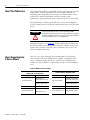
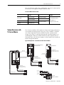
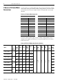
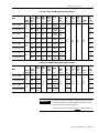
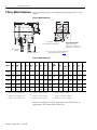
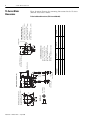
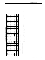
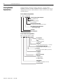
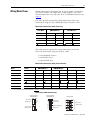
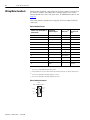
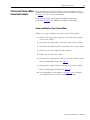
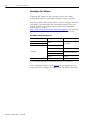
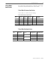
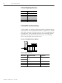
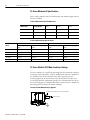
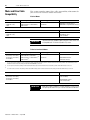
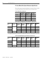
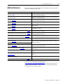
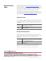
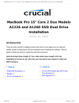
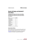
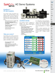
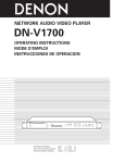
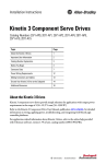
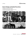
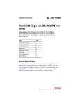
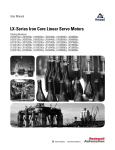
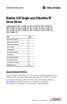
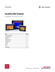
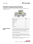
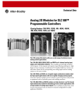
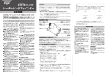
1
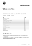
Technical Data
Y-Series Motor Conversions
Catalog Numbers
Y-1002-2, Y-1003-2, Y-2006-2, Y-2012-2, Y-3023-2
1
Topic
Page
About This Publication
2
About Converting from Y-Series Motors
2
System Overview with TL-Series Motors
3
Y-Series to TL-Series Motor Conversions
4
Y-Series Motor Dimensions
6
TL-Series Motor Dimensions
8
Catalog Number Explanations
10
Wiring Motor Power
11
Wiring Motor Feedback
12
Y-Series to TL-Series Motor Conversion Example
13
Y-Series Motor Specifications
15
TL-Series Motor Specifications
17
Motor and Drive Cable Compatibility
20
Drive/Motor System Combinations
21
Additional Resources
23
Publication Y-TD001A-EN-P — April 2008
2
Y-Series Motor Conversions
About This Publication
This publication provides a migration path for replacing your Y-Series
motor with a TL-Series (Bulletin TLY) servo motor. Included are
mounting and wiring differences between the motor families. Also
included are motor specifications and drive/motor system
performance specifications for your Y-Series to TL-Series conversion.
This publication is written specifically for systems converting from
Y-Series motors paired with Kinetix 2000, Kinetix 6000, and Ultra3000
drives.
ATTENTION
While executing the migration, a risk assessment should be
conducted to make sure that all task-hazard combinations have been
identified and addressed. The risk assessment may require additional
circuitry to reduce the risk to an acceptable level.
Additional Resources, on page 23, contains publication numbers for
the Kinetix Motion Control Selection Guide, the Motion Analyzer CD,
and the drive manuals you will need to complete your Y-Series to
TL-Series motor conversion.
About Converting from
Y-Series Motors
You can reuse your existing Y-Series motor power and feedback
cables with the TL-Series (Bulletin TLY) motors. The Bulletin TLY
cables, designed specifically for use with TL-Series (Bulletin TLY)
motors, are also available as replacements or for use with additional
axes.
Y-Series Motor Conversion Cables
Y-Series Motor Cables
(Bulletin TLY motor compatible)
Cable Type
TL-Series (Bulletin TLY) Motor Cables
Cable Cat. No.
Cable Type
Cable Cat. No.
2090-XXNFY-Sxx
(flying-leads at drive end)
-->
2090-UXNFBY-Sxx
(connector at drive end)
-->
2090-CFBM6DD-CCAAxx
(connector at drive end)
Power (only)
N/A
--> Power (only)
2090-CPWM6DF-16AAxx
Power with brake wires
2090-XXNPY-16Sxx
or
2090-UXNPAY-16Sxx
--> Power with brake wires
2090-CPBM6DF-16AAxx
Incremental feedback
Publication Y-TD001A-EN-P — April 2008
Incremental feedback
2090-CFBM6DF-CBAAxx
(flying-leads at drive end)
Y-Series Motor Conversions
3
For each TL-Series motor/drive combination, you need a connector kit
to terminate the flying-lead motor feedback cable.
TL-Series Motor Connector Kits
Servo Drive Family
Kinetix 2000
Connector Kit
Cat. No.
Cable Type
2090-K2CK-D15M (1)
Incremental feedback
2090-K6CK-D15M
Ultra3000
2090-UXBB-D15M
(1)
2090-CFBM6DF-CBAAxx
Incremental feedback and I/O or
2090-XXNFY-Sxx
(flying-leads at drive end)
Incremental feedback
2090-K2CK-COMBO (1)
Kinetix 6000
Feedback Cable
Cat. No.
Battery backup is not required for incremental feedback applications.
System Overview with
TL-Series Motors
The TL-Series (Bulletin TLY) motors are low-inertia high-performance
servo motors featuring metric frame sizes. They combine a compact
size with a high-torque density afforded by their superior stator
design. The result is a package that provides substantial power in a
small footprint. When used with the Kinetix 2000, Kinetix 6000, or
Ultra3000 drives, the TL-Series motors are able to offer the benefits of
Kinetix Integrated Motion.
Typical Configuration - Servo Drives with TL-Series Motors
Kinetix 2000 IAM/AM Module
(IAM module shown)
Ultra3000 Drive
2090-UXBB-D15M
Drive-mounted Connector Kit for
Motor Feedback (CN2) Connector
Motor Power
(MP) Connector
Motor Power
TB1 Connections
Kinetix 6000 IAM/AM Module
(IAM module shown)
2090-K2CK-D15M or
2090-K2CK-COMBO
Low-profile Connector Kit for
Motor Feedback (MF) Connector
Motor Feedback Cable
Motor Feedback Cable
Motor Power Cable
Motor Power Cable
2090-K6CK-D15M
Low-profile Connector Kit for
Motor Feedback (MF) Connector
Motor Feedback Cable
Motor Power Cable
Feedback
Connector
Power
Connector
TL-Series
(Bulletin TLY) Motors
Publication Y-TD001A-EN-P — April 2008
4
Y-Series Motor Conversions
Y-Series to TL-Series Motor
Conversions
Use this table as a starting point for your Y-Series to TL-Series motor
conversion. Find your Y-Series motor catalog number and read across
to determine the TL-Series motor with the best possible conversion
solution.
Y-Series to TL-Series Motor Conversions
Y-Series Motors
Cat. No.
Description
Y-1002-2-H00AA
No brake
Y-1002-2-H04AA
TL-Series (Bulletin TLY) Motors
Cat. No.
Description
--->
TLY-A120T-HK62AA
No brake
Brake
--->
TLY-A120T-HK64AA
Brake
Y-1003-2-H00AA
No brake
--->
TLY-A130T-HK62AA
No brake
Y-1003-2-H04AA
Brake
--->
TLY-A130T-HK64AA
Brake
Y-2006-2-H00AA
No brake
--->
TLY-A220T-HK62AA
No brake
Y-2006-2-H04AA
Brake
--->
TLY-A220T-HK64AA
Brake
Y-2012-2-H00AA
No brake
--->
TLY-A230T-HK62AA
No brake
Y-2012-2-H04AA
Brake
--->
TLY-A230T-HK64AA
Brake
Y-3023-2-H00AA
No brake
--->
TLY-A2540P-HK62AA
No brake
Y-3023-2-H04AA
Brake
--->
TLY-A2540P-HK64AA
Brake
Use these tables to find your Y-Series motor catalog number and
compare the significant differences in specifications to the TL-Series
motor beneath it.
Y-10xx to TLY-A1xxT-H Motor Specifications Summary
Motor
Y-1002-2-H00AA
TLY-A120T-HK62AA
Brake
Option
No
brake
Y-1002-2-H04AA
Cont.
Rated Torque
Speed Nm
RPM
(lb-in)
Peak
Torque
Nm
(lb-in)
Motor
Rated
Output
kW
Rotor
Inertia
kg-m2
(lb-in-s2)
Shaft
Dia.
mm (in.)
Pilot
Dia.
mm (in.)
Bolt
Circle
Dia.
mm (in.)
Bolt
Hole
Dia.
mm (in.)
Flange
mm (in.)
4500
0.17
(1.5)
0.48
(4.3)
0.069
0.0000031
(0.000027)
95.0
(3.74)
6000
0.181
(1.60)
0.36
(3.20)
0.086
0.000002
(0.000018)
84.5
(3.33)
4500
0.17
(1.5)
0.48
(4.3)
0.069
0.0000039
(0.000034)
133.5
(5.26)
6000
0.163
(1.44)
0.36
(3.20)
0.077
0.000005
(0.000044)
5000
0.35
(3.1)
0.97
(8.6)
0.12
0.0000051
(0.000045)
6000
0.325
(2.88)
0.76
(6.70)
0.14
0.000003
(0.000027)
98.5
(3.88)
5000
0.35
(3.1)
0.97
(8.6)
0.12
0.0000059
(0.000052)
151.5
(5.96)
6000
0.293
(2.59)
0.76
(6.70)
0.13
0.000006
(0.000053)
134.1
(5.28)
Brake
TLY-A120T-HK64AA
Y-1003-2-H00AA
TLY-A130T-HK62AA
No
brake
Y-1003-2-H04AA
Brake
TLY-A130T-HK64AA
Motor
Length
mm (in.)
Publication Y-TD001A-EN-P — April 2008
8.0
(0.31)
30.0
(1.18)
46.0
(1.81)
4.5
(0.18)
40.0
(1.57)
120.1
(4.73)
113.0
(4.45)
Y-Series Motor Conversions
5
Y-20xx to TLY-A2xxT-H Motor Specifications Summary
Motor
Y-2006-2-H00AA
TLY-A220T-HK62AA
Brake
Option
No
brake
Y-2006-2-H04AA
Cont.
Rated Torque
Speed Nm
RPM
(lb-in)
Peak
Torque
Nm
(lb-in)
Motor
Rated
Output
kW
Rotor
Inertia
kg-m2
(lb-in-s2)
Shaft
Dia.
mm (in.)
Y-2012-2-H00AA
TLY-A230T-HK62AA
No
brake
Y-2012-2-H04AA
Bolt
Hole
Dia.
mm (in.)
Flange
mm (in.)
Motor
Length
mm (in.)
0.69
(6.1)
1.92
(17.0)
0.23
0.000015
(0.00013)
14.0
(0.55)
125.5
(4.94)
6000
0.836
(7.40)
1.48
(13.1)
0.35
0.000018
(0.00016)
12.0
(0.47)
106.1
(4.18)
5000
0.69
(6.1)
1.92
(17.0)
0.23
0.000020
(0.00018)
14.0
(0.55)
163.5
(6.44)
6000
0.757
(6.70)
1.48
(13.1)
0.24
0.000028
(0.00025)
12.0
(0.47)
140.7
(5.54)
4500
1.4
(12.0)
3.8
(33.7)
0.51
0.000026
(0.00023)
14.0
(0.55)
6000
1.30
(11.50)
3.05
(27.0)
0.44
0.000034
(0.00030)
12.0
(0.47)
128.0
(5.04)
4500
1.4
(12.0)
3.8
(33.7)
0.51
0.000032
(0.00028)
14.0
(0.55)
191.5
(7.54)
6000
1.16
(10.3)
3.05
(27.0)
0.32
0.000044
(0.00039)
12.0
(0.47)
162.6
(6.40)
Brake
TLY-A230T-HK64AA
Bolt
Circle
Dia.
mm (in.)
5000
Brake
TLY-A220T-HK64AA
Pilot
Dia.
mm (in.)
50.0
(1.97)
70.0
(2.76)
5.5
(0.22)
60.0
(2.36)
153.5
(6.04)
Y-3023 to TLY-A2540P-H Motor Specifications Summary
Motor
Y-3023-2-H00AA
TLY-A2540P-HK62AA
Brake
Option
No
brake
Y-3023-2-H04AA
Cont.
Rated Torque
Speed Nm
RPM
(lb-in)
Peak
Torque
Nm
(lb-in)
Motor
Rated
Output
kW
Rotor
Inertia
kg-m2
(lb-in-s2)
Pilot
Dia.
mm (in.)
Bolt
Circle
Dia.
mm (in.)
Bolt
Hole
Dia.
mm (in.)
Flange
mm (in.)
Motor
Length
mm (in.)
4500
2.5
(22.5)
0.91
0.000064
(0.00056)
70.0
(2.76)
180.0
(7.09)
5000
2.94
(26.0)
0.86
0.00011
(0.00096)
80.0
(3.15)
143.7
(5.66)
4500
2.5
(22.5)
0.91
0.000069
(0.00061)
5000
2.94
(26.0)
0.66
0.00013
(0.0012)
7.10
(63.0)
Brake
TLY-A2540P-HK64AA
Shaft
Dia.
mm (in.)
IMPORTANT
16.0
(0.63)
70.0
(2.76)
80.0
(3.15)
90.0
(3.54)
6.6
(0.26)
80.0
(3.15)
220.5
(8.68)
180.3
(7.10)
If your drive system software doesn’t include the Bulletin TLY motors
in the motion database, you’ll need to update your database before
configuring the motor and drive properties.
Refer to Reconfigure Your Software on page 14 for more information.
Publication Y-TD001A-EN-P — April 2008
6
Y-Series Motor Conversions
Y-Series Motor Dimensions
These drawings illustrate the mounting dimensions for the Y-Series
motors.
Y-Series Motor Dimensions
AB
M
L
LB
L-LB
EC
ED
EA
D
EB
H
T
LD
LE
LC
LF
S is the diameter of the hole.
SS is the diameter of the bolt circle.
LA
CAB
W2
W2
Motor Feedback
Connector
Shaft End Threaded Hole
Y-2006, Y-2012, Y-3023:
Thread - M5 x 0.8 mm (0.0315 in.)
Thread Depth - 12 mm (0.47 in.)
LA, LC, LD, LE, LF, W1, and W2 are Supplemental
Y-Series Motor Dimensions on page 7.
Motor Power Connector
Y-Series Motor Dimensions
Motor
AB (3)
mm
(in.)
CAB (7) D
mm
mm
(in.)
(in.)
Y-1002
40
(1.58)
1100
(43.34)
Y-1003
40
(1.58)
Y-2006
EB (2)
mm
(in.)
EC (3)
mm
(in.)
ED
mm
(in.)
H (5)
mm
(in.)
L
mm
(in.)
8 (8)
(0.31) –
–
5
(0.20)
–
30
(1.18)
1100
(43.34)
8 (8)
(0.31) –
–
5
(0.20)
–
60
(2.36)
1100
(43.34)
14 (9) –
(0.55)
–
6
(0.24)
Y-2012
60
(2.36)
1100
(43.34)
14 (9) –
(0.55)
–
Y-3023
80
(3.15)
1100
(43.34)
16 (9) 35
(0.63) (1.38)
19.5
(0.77)
(1)
(2)
(3)
EA (2)
mm
(in.)
Tolerance is ±0.2 mm (±0.00788 in.).
(4)
Tolerance is ±0.3 mm (±0.01182 in.).
(5)
Tolerance is ±0.5 mm (±0.0197 in.).
(6
LB (5)
with
Brake
mm
(in.)
LB (5)
mm
(in.)
M
L-LB (4) mm
mm (in.) (in.)
S (1)
mm
(in.)
SS (1)
mm
(in.)
T (2)
mm
(in.)
95
108.5
(3.74) (4.27)
70
(2.75)
25
(0.98)
30
(1.18)
4.5
(0.18)
46
(1.81)
2.5
(0.10)
30
(1.18)
113
126.5
(4.45) (4.98)
88
(3.46)
25
(0.98)
30
(1.18)
4.5
(0.18)
46
(1.81)
2.5
(0.10)
–
41
(1.61)
125.5 133.5
(4.94) (5.3)
95.5
(3.76)
30
(1.18)
50
(1.97)
5.5
(0.22)
70
(2.75)
3.0
(0.12)
6
(0.24)
–
41
(1.61)
153.5 161.5
(6.04) (6.36)
123.5
(4.87)
30
(1.18)
50
(1.97)
5.5
(0.22)
70
(2.75)
3.0
(0.12)
8
(0.31)
2.0
52
(0.08) (2.05)
180
180.5
(7.09) (7.11)
140
(5.57)
40
(1.57)
70
(2.75)
6.6
(0.26)
90
(3.54)
3.0
(0.12)
Tolerance is ±0.8 mm (±0.03152 in.).
(7)
Tolerance is ±100 mm (±3.94 in.).
Tolerance is ±1.0 mm (±0.0394 in.).
(8)
Tolerance is –0.009 mm (–0.0004 in.).
Tolerance is ±2.0 mm (±0.0788 in.).
(9)
Tolerance is –0.011 mm (–0.0004 in.).
Motors are designed to metric dimensions. Inch dimensions are
approximate conversions from millimeters.
Publication Y-TD001A-EN-P — April 2008
Y-Series Motor Conversions
7
Supplemental Y-Series Motor Dimensions
Motor
LA (2)
mm (in.)
Y-1002
Y-1003
Y-2006
23.5 (0.90)
LC
mm (in.)
LC (1) (2)
(Brake)
m (in.)
17.5 (0.7)
56 (2.2)
(1) (2)
LD
mm (in.)
LD (2)
(Brake)
mm (in.)
–
–
(2)
LE
mm (in.)
LE (1) (4)
(Brake)
mm (in.)
LF (5)
mm (in.)
W1 (5)
mm (in.)
–
–
21.5 (0.84)
6 (0.24)
66 (2.6)
24 (0.95)
68.5 (2.7)
30 (1.2)
(4)
41.5 (1.60)
Y-2012
69.5 (2.7)
Y-3023
80.5 (3.2)
–
–
7 (0.28)
45 (1.77)
28 (1.1)
W2 (5)
mm (in.)
8 (0.32)
6.7 (0.27)
1
Measurement is to the center of the perpendicular motor encoder cable. Motor encoder cable exits perpendicular to the frame on Y-1002 and Y-1003 motors (not as
shown).
2
Tolerance is ±2.0 mm (±0.0788 in.).
3
Tolerance is ±0.5 mm (±0.0197 in.).
4
Tolerance is ±2.5 mm (±0.0985 in.).
5
Tolerance is ±1.0 mm (±0.0394 in.).
Motors are designed to metric dimensions. Inch dimensions are
approximate conversions from millimeters.
Publication Y-TD001A-EN-P — April 2008
Publication Y-TD001A-EN-P — April 2008
Shaft Detail
BE
LE
Feedback
Connector
No threaded
hole in shaft.
HD
LB
TB
L-LB
Shaft Diameter Tolerances
NB
P
0.02 (0.001)
0.06 (0.0024)
0.07 (0.003)
Shaft Runout (T.I.R.)
Pilot Eccentricity (T.I.R.)
Max Face Runout (T.I.R.)
N
0.02 (0.001)
0.07 (0.003)
0.06 (0.0024)
0.07 (0.003)
0.06 (0.0024)
0.02 (0.001)
TLY-A25xx
TLY-A2540 Motors:
Ø 69.970…70.000 (2.7547…2.7556)
TLY-A220 and TLY-A230 Motors:
Ø 49.975…50.000 (1.9675…1.9685)
Pilot Diameter Tolerances
TLY-A120, and TLY-A130 Motors:
Ø 29.979…30.000 (1.1803…1.1811)
Pilot Diameter
TLY-A2xx
TLY-A2540 Motors:
Ø 15.989…16.000 (0.6295…0.6299)
TLY-A220 and TLY-A230 Motors:
Ø 11.989…12.000 (0.4720…0.4724)
TLY-A120 and TLY-A130 Motors:
Ø 7.991…8.000 (0.3146…0.3150)
TLY-A1xx
D Shaft Diameter
S Diameter Holes on
M Diameter Bolt Circle
Shaft, Pilot, and Keyway
Tolerances
1000 (39.4)
±50 (1.97)
T
Power
Connector
LA
L
TL-Series Motor
Dimensions
AD
Mounting pattern has two holes
for TLY-A120 and TLY-A130 (shown).
All others have four holes.
Dimensions are in mm (in.)
8
Y-Series Motor Conversions
These drawings illustrate the mounting dimensions for the TL-Series
(Bulletin TLY) metric motors.
TL-Series Motor Dimensions (TLY-Axxxx-HK6xAA)
(2)
(1)
27.6
(1.09)
27.6
(1.09)
53.0
(2.09)
21.0
(0.83)
BE
mm
(in.)
43.0
(1.69)
31.1
(1.22)
AD
mm
(in.)
16.0
(0.63)
12.0
(0.47)
8.0
(0.31)
D
mm
(in.)
93.0
(3.66)
73.0
(2.87)
51.1
(2.01)
HD
mm
(in.)
143.7
(5.66)
128.0
(5.04)
106.1
(4.18)
98.5
(3.88)
84.5
(3.33)
L (1)
mm
(in.)
35.0
(1.38)
30.0
(1.18)
25.0
(0.98)
L-LB (2)
mm (in.)
8.0
(0.32)
6.0
(0.24)
5.0
(0.20)
LA
mm
(in.)
108.7
(4.28)
98.1
(3.86)
76.1
(3.00)
73.5
(2.89)
59.5
(2.34)
LB (1)
mm
(in.)
43.8
(1.72)
42.8
(1.69)
39.1
(1.54)
LE (1)
mm
(in.)
Tolerance for this dimension is ±1.0 mm (±0.039 in.).
90.0
(3.54)
70.0
(2.76)
46.0
(1.81)
M
mm
(in.)
70.0
(2.76)
50.0
(1.97)
30.0
(1.18)
N
mm
(in.)
34.0
(1.34)
27.0
(1.06)
20.0
(0.79)
NB
mm
(in.)
80.0
(3.15)
60.0
(2.36)
40.0
(1.57)
P
mm
(in.)
6.6
(0.26)
5.5
(0.22)
4.5
(0.18)
S
mm
(in.)
3.0
(0.12)
3.0
(0.12)
2.5
(0.10)
T
mm
(in.)
7.0
(0.28)
7.0
(0.28)
4.5
(0.18)
TB
mm
(in.)
Motors are designed to metric dimensions. Inch dimensions are approximate conversions from
millimeters. Dimensions without tolerances are for reference.
If ordering an TLY-A2540 motor with brake, add 36.6 mm (1.44 in.) to dimensions L, LB, and LE.
If ordering an TLY-A220 or TLY-A230 motor with brake, add 34.6 mm (1.36 in.) to dimensions L, LB, and LE.
If ordering an TLY-A120 or TLY-A130 motor with brake, add 35.6 mm (1.40 in.) to dimensions L, LB, and LE.
A2540
A230
A220
A130
A120
Motor
Series
TLY-
TL-Series Motor Dimensions (TLY-Axxxx-HK6xAA)
Y-Series Motor Conversions
9
Publication Y-TD001A-EN-P — April 2008
10
Y-Series Motor Conversions
Catalog Number
Explanations
Catalog numbers consist of various characters, each of which
identifies a specific version or option for that component. Use these
configuration charts to understand the Y-Series and TL-Series motor
catalog numbers.
Y-Series Motor Catalog Numbers
Y - xxxx - x - H 0x AA
Factory Designated Special Options
AA = Standard (metric)
Options
00 = No brake (standard)
04 = 24V dc brake
Optical Encoder Line Count
H = Incremental encoder (2000 lines/revolution)
Motor Winding Voltage Designator
1 = 115V Drive input voltage
2 = 230V Drive input voltage
Frame Size
Series Designator
TL-Series Motor Catalog Numbers
TLY - x xx xx x -H K 6 x AA
Factory Options
AA = Standard (metric)
Brake
2 = No brake (standard)
4 = 24V dc brake
Connectors
6 = Cables with circular connectors, 1 m (39.4 in.)
Enclosure/Shaft Key/Shaft Seal
K = IP65 housing/No shaft key/No shaft seal
Feedback
H = Incremental encoder (2000 lines/revolution)
Rated Speed
P = 5000 rpm
T = 6000 rpm
Magnet Stack Length
Frame Size
1 = 46 mm (1.81 in.)
2 = 70 mm (2.75 in.)
25 = 90 mm (3.54 in.)
Voltage Rating
A = 230V ac
D = 115V ac (not available at this time)
Series Designator
Publication Y-TD001A-EN-P — April 2008
Y-Series Motor Conversions
Wiring Motor Power
11
Wiring motor power connections for TL-Series motors is identical to
the Y-Series motors. For motor/drive wiring diagrams, refer to the
documentation that came with your drive, or Additional Resources on
page 23.
This table provides pinouts for wiring motor power drive-end
connections using the 2090-CPWM6DF-16AAxx feedback cable.
Motor Power Connections (motor power only)
Kinetix 2000 and Kinetix 6000
IAM/AM Modules
Servo Motor
Ultra3000 Drives
TL-Series
Pin
Signal
Pin
Signal
U / Brown
MP-1
U
TB1
U
V / Black
MP-2
V
TB1
V
W / Blue
MP-3
W
TB1
W
Yellow/Green MP-4
This table provides pinouts for wiring motor power and brake
drive-end connections using any of these cables:
• 2090-CPBM6DF-16AAxx
• 2090-XXNPY-16Sxx
• 2090-UXNPAY-16Sx
Motor Power Connections (motor power and brake)
Y-Series Servo
Motors
TL-Series Servo
Motors
Wire / Color
Wire / Color
Kinetix 2000
IAM/AM Modules
Kinetix 6000
IAM/AM Modules
Ultra3000 Drives
Pin
Signal
Pin
Signal
Pin
Signal
1 / Black
---> U / Brown
MP-1
U
MP-1
U
TB1
U
2 / Black
---> V / Black
MP-2
V
MP-2
V
TB1
V
3 / Black
---> W / Blue
MP-3
W
MP-3
W
TB1
W
Green/Yellow
--->
7 / White
---> 7 / White
BC-2
MBRK+
BC-5
MBRK+
CN1-43 (1)
Relay Output +
9 / Black
---> 9 / Black
BC-3
MPRK-
BC-6
MPRK-
CN1-44 (1)
Relay Output -
MP-4
Refer to Ultra3000 Integration Manual, publication 2098-IN005, for additional motor brake circuitry required between the Ultra3000 drive and motor with brake.
Motor Power and Brake Connectors
Motor Power
(MF) Connector
U
V
W
W
V
U
MBRK MBRK +
COM
PWR
DBRK DBRK +
1 2 3 4
PWR
MBRK +
MBRK COM
Kinetix 6000 Drive
IAM/AM Module
1 2 3 4 5 6
Motor Brake
(BC) Connector
4 3 2 1
Kinetix 2000 Drive
IAM/AM Module
4 3 2 1
(1)
Yellow/Green MP-4
Motor Power
(MF) Connector
Ultra3000 Drive
U
V
Motor/Dynamic Brake
(BC) Connector
Motor
Motor Power
(TB1) Connector
W
Publication Y-TD001A-EN-P — April 2008
12
Y-Series Motor Conversions
Wiring Motor Feedback
Wiring motor feedback connections for TL-Series motors is identical to
the Y-Series motors. For motor/drive wiring diagrams, refer to the
documentation that came with your drive, or Additional Resources on
page 23.
This table provides pinouts for wiring the TL-Series motor feedback
connector.
Motor Feedback Pinouts
Y-Series or TL-Series Motor (1)
Connector Pin
Incremental
Feedback Signal
Wire Color (2)
Drive (3)
Connector Kit
Pin
9
AM+
Black
1
10
AM-
White/Black
2
11
BM+
Red
3
12
BM-
White/Red
4
13
IM+
Green
5
14
IM-
White/Green
10
15
S1
White/Blue
12
17
S2
Yellow (4)
13
19
S3
White/Yellow (5)
8
22
EPWR_5V
Grey
14
23
ECOM
White/Grey
6
24
Shield
–
Connector
Housing
(1)
All other motor connector pins are reserved.
(2)
Wire colors for 2090-CFBM6DF-CBAAxx cable is shown.
(3)
Motor feedback drive connector is MF for Kinetix 2000 and Kinetix 6000 drives, and CN2 for Ultra3000 drives.
(4)
Wire color for 2090-XXNFY-Sxx feedback cable (pin 17) is blue.
(5)
Wire color for 2090-XXNFY-Sxx feedback cable (pin 19) is brown.
Motor Feedback Connector
15-pin
Motor Feedback Connector
Pin 15
Pin 11
Pin 6
Publication Y-TD001A-EN-P — April 2008
Pin 10
Pin 5
Pin 1
Y-Series Motor Conversions
Y-Series to TL-Series Motor
Conversion Example
13
These procedures assume that you have your equivalent TL-Series
(Bulletin TLY) motor (refer to Y-Series to TL-Series Motor Conversions
on page 4) and are ready for installation.
Refer to the TL-Series Servo Motors Installation Instructions,
publication TL-IN003, for additional installation information.
Remove and Replace Your Y-Series Motor
Follow these steps to remove and replace your Y-Series motor.
1. Remove three-phase power from the servo drive that controls
your Y-Series motor.
2. Disconnect the motor power cable from your Y-Series motor.
3. Disconnect the motor feedback cable from your Y-Series motor.
4. Remove the Y-Series motor from the machine.
5. Install your new TL-Series motor.
6. Reconnect the motor power cable to your new TL-Series motor.
Refer to Wiring Motor Power on page 11.
7. Reconnect the motor feedback cable to your TL-Series motor.
Refer to Wiring Motor Feedback on page 12.
8. Go to Reconfigure Your Software, on page 14, to reconfigure
your software for the new drive/motor combination.
Publication Y-TD001A-EN-P — April 2008
14
Y-Series Motor Conversions
Reconfigure Your Software
If Bulletin TLY motors are not selectable in your drive/motor
configuration software, your motion database requires updating.
Refer to the table below for the software used to configure your drive
and motor. If you determine that your motion database does not
include the TLY-Axxxx motors, go to the Rockwell Automation
Knowledgebase website,
http://www.rockwellautomation.com/knowledgebase and search for
Adding Bulletin TLY Motors to the Motion Database (ID 50909).
Drive/Motor Configuration Software
Drive Family
Kinetix 2000
Kinetix 6000
Drive Type
SERCOS
Software
RSLogix 5000
SERCOS
Analog
Ultra3000
DeviceNet
DeviceNet with Indexing
Ultra 100 and Ultra 200 Series
(1)
Ultraware and RSLogix 5000 (1)
Ultraware and RSNetWorx
Indexing
Ultraware
All drive types
Ultra Master
Use RSLogix 5000 software when the 1756-M02AE analog module controls the Ultra3000 drive.
Refer to Additional Resources on page 23 for the appropriate user
manual to further configure the software for your motor conversion.
Publication Y-TD001A-EN-P — April 2008
Y-Series Motor Conversions
Y-Series Motor
Specifications
15
This section provides motor performance, motor brake, motor weight,
and load-force rating specifications for the Y-Series motors.
Y-Series Motor Performance Specifications
Y-Series motors are available with 230V windings.
Y-Series (230V) Performance Specifications
Motor
Max Speed
rpm
Continuous
Stall Torque
Nm (lb-in)
Peak
Stall Torque
Nm (lb-in)
Motor Rated
Output
kW
Rotor Inertia (1)
kg-m2 (lb-in-s2)
Y-1002-2
4500
0.17 (1.5)
0.48 (4.3)
0.069
0.0000031 (0.000027)
Y-1003-2
5000
0.35 (3.1)
0.97 (8.6)
0.12
0.0000051 (0.000045)
Y-2006-2
5000
0.69 (6.1)
1.92 (17)
0.23
0.000015 (0.00013)
Y-2012-2
4500
1.4 (12)
3.8 (33.7)
0.51
0.000026 (0.00023)
Y-3023-2
4500
2.5 (22.5)
7.1 (63)
0.91
0.000064 (0.00056)
(1)
Refer to Y-Series Motor Brake Specifications for Brake Motor Inertia.
Y-Series Motor Brake Specifications
Motor
Holding Torque
Nm (lb-in)
Y-1002
(0.157) 1.39
Y-1003
(0.32) 2.83
Y-2006
(0.637) 5.64
Y-2012
(1.274) 11.24
Y-3023
(2.38) 21.06
Coil Current
at 24V dc
A
0.26
0.31
0.37
Brake Motor Inertia
kg-m2 (lb-in-s2)
Brake Motor Weight
kg (lb)
0.0000039 (0.000034)
0.5 (1.1)
0.0000059 (0.000052)
0.7 (1.5)
0.000020 (0.00018)
1.3 (2.9)
0.000032 (0.00028)
1.9 (4.1)
0.000069 (0.00061)
3.5 (7.8)
Publication Y-TD001A-EN-P — April 2008
16
Y-Series Motor Conversions
Y-Series Weight Specifications
Motor
Motor Weight, Approx.
kg (lb)
Y-1002
0.5 (1.1)
Y-1003
0.7 (1.5)
Y-2006
1.3 (2.9)
Y-2012
1.9 (4.1)
Y-3023
3.5 (7.8)
Y-Series Motor Load-force Ratings
Y-Series motors are capable of operating with the maximum radial or
axial shaft loads as listed. Radial loads listed are applied in the middle
of the shaft extension. The table represents an L10 bearing-fatigue life
of 20,000 hours. This 20,000-hour life does not account for possible
application-specific life reduction that may occur due to bearing
grease contamination from external sources.
Location on Shaft Where Rating Is Applied
LR
FR
2LR/3
F
Y-Series Motor Load Forces
Shaft Radial Load (FR) (1)
kg (lb)
Axial Load (F) (1)
kg (lb)
10 (22.05)
3 (6.615)
Y-2006
20 (44.1)
8 (17.64)
Y-2012
25 (55.125)
10 (22.05)
Y-3023
35 (77.175)
20 (44.1)
Motor Series
Y-1002
Y-1003
(1)
Publication Y-TD001A-EN-P — April 2008
The FR and F refer to loads applied as shown in the drawing above.
Y-Series Motor Conversions
TL-Series Motor
Specifications
17
This section provides motor performance specifications for the
TL-Series motors.
TL-Series Motor Performance Specifications
These tables provide performance specifications for TL-Series motors
with and without holding brakes.
TL-Series (Non-brake) Motor Performance Specifications
Motor
Max Speed
rpm
Continuous
Stall Torque
Nm (lb-in)
Peak
Stall Torque
Nm (lb-in)
Motor Rated
Output
kW
Speed at Motor
Rated Output
rpm
Rotor Inertia
kg-m2 (lb-in-s2)
TLY-A120T
0.181 (1.60)
0.36 (3.20)
0.086
5000
0.000002 (0.000018)
TLY-A130T
0.325 (2.88)
0.76 (6.70)
0.14
5000
0.000003 (0.000027)
0.836 (7.40)
1.48 (13.1)
0.35
5000
0.000018 (0.00016)
TLY-A220T
6000
TLY-A230T
TLY-A2540P
5000
1.30 (11.50)
3.05 (27.0)
0.44
5000
0.000034 (0.00030)
2.94 (26.0)
7.10 (63.0)
0.86
4575
0.00011 (0.00096)
TL-Series (Brake) Motor Performance Specifications
Motor
Max Speed
rpm
TLY-A120T
TLY-A130T
TLY-A220T
6000
TLY-A230T
TLY-A2540P
5000
Continuous
Stall Torque
Nm (lb-in)
Peak
Stall Torque
Nm (lb-in)
Motor Rated
Output
kW
Speed at Motor
Rated Output
rpm
Rotor Inertia
kg-m2 (lb-in-s2)
0.163 (1.44)
0.36 (3.20)
0.077
5000
0.000005 (0.000044)
0.293 (2.59)
0.76 (6.70)
0.13
5000
0.000006 (0.000053)
0.757 (6.70)
1.48 (13.1)
0.24
5000
0.000028 (0.00025)
1.16 (10.3)
3.05 (27.0)
0.32
4250
0.000044 (0.00039)
2.94 (26.0)
7.10 (63.0)
0.66
3750
0.00013 (0.0012)
TL-Series Motor Brake Specifications
Brake Response Time
Motor
Max Backlash
(brake engaged)
arc minutes
TLY-A120T
TLY-A130T
TLY-A220T
TLY-A230T
TLY-A2540P
60
Holding
Torque
Nm (lb-in)
Coil Current
at 24V dc
A
Release
ms
Engage (using external
arc suppression device)
MOV ms
Diode ms
0.32 (2.8)
0.18…0.22
21
7
40
1.24 (11.0)
0.333…0.407
22
13
73
2.5 (22.0)
0.351…0.429
42
14
86
Publication Y-TD001A-EN-P — April 2008
18
Y-Series Motor Conversions
TL-Series Mechanical Specifications
These tables provide shaft-seal dimensions and motor weights for the
TL-Series motors.
TL-Series Motor Shaft Seal Kit Dimensions
Motor Series
Catalog Number
Inside Diameter
mm (in.)
Outside Diameter
mm (in.)
Width
mm (in.)
TLY-A1xx
TL-SSN-1
8.9 (0.35)
16 (0.71)
3 (0.12)
TLY-A2xx
TL-SSN-2
14 (0.55)
24 (0.95)
5 (0.20)
TLY-A25xx
TL-SSN-3
19.8 (0.78)
30 (1.18)
5 (0.20)
TL-Series Motor Weight Specifications
High Resolution Feedback Option
Incremental Feedback Option
Motor
Motor Weight, Approx.
kg (lb)
Brake Motor Weight, Approx. Motor Weight, Approx.
kg (lb)
kg (lb)
Brake Motor Weight, Approx.
kg (lb)
TLY-A120T
0.34 (0.75)
0.59 (1.3)
0.35 (0.78)
0.59 (1.3)
TLY-A130T
0.46 (1.0)
0.68 (1.5)
0.50 (1.1)
0.68 (1.5)
TLY-A220T
0.95 (2.1)
1.4 (3.0)
1.1 (2.4)
1.5 (3.4)
TLY-A230T
1.4 (3.0)
1.8 (4.0)
1.5 (3.3)
2.0 (4.4)
TLY-A2540P
2.6 (5.7)
3.5 (7.7)
2.6 (5.8)
3.5 (7.7)
TL-Series (Bulletin TLY) Motor Load-force Ratings
TL-Series motors are capable of operating with the maximum radial or
maximum axial shaft loads as listed. Radial loads listed are applied in
the middle of the shaft extension. The tables represent an L10
bearing-fatigue life of 20,000 hours. This 20,000-hour life does not
account for possible application-specific life reduction that may occur
due to bearing grease contamination from external sources. Maximum
operating speed is limited by motor winding.
Location on Shaft Where Rating Is Applied
Radial load force applied at center of shaft extension.
Axial Load Force
Publication Y-TD001A-EN-P — April 2008
Y-Series Motor Conversions
19
Radial Load Force Ratings
Motor Series
1000 rpm
kg (lb)
2000 rpm
kg (lb)
3000 rpm
kg (lb)
4500 rpm
kg (lb)
5000 rpm
kg (lb)
TLY-A120T
12 (26)
10 (21)
8 (18)
–
7 (15)
TLY-A130T
13 (29)
10 (23)
9 (20)
–
8 (17)
TLY-A220T
27 (60)
22 (48)
19 (42)
–
16 (35)
TLY-A230T
31 (68)
24 (54)
21 (47)
–
18 (40)
TLY-A2540P
50 (110)
39 (87)
34 (76)
–
29 (64)
Axial Load Force Ratings (maximum radial load)
Motor Series
1000 rpm
kg (lb)
2000 rpm
kg (lb)
3000 rpm
kg (lb)
4500 rpm
kg (lb)
5000 rpm
kg (lb)
TLY-A120T
9 (20)
7 (16)
5 (12)
–
5 (10)
TLY-A130T
10 (22)
8 (17)
6 (13)
–
5 (11)
TLY-A220T
15 (32)
11 (24)
9 (20)
–
7 (16)
TLY-A230T
15 (34)
12 (26)
10 (21)
–
8 (17)
TLY-A2540P
18 (39)
13 (29)
11 (25)
–
9 (20)
Axial Load Force Ratings (zero radial load)
Motor Series
1000 rpm
kg (lb)
2000 rpm
kg (lb)
3000 rpm
kg (lb)
4500 rpm
kg (lb)
5000 rpm
kg (lb)
TLY-A120T
12 (26)
9 (20)
7 (16)
–
6
TLY-A130T
12 (26)
9 (20)
7 (16)
–
6
TLY-A220T
19 (41)
14 (30)
11 (25)
–
9
TLY-A230T
19 (41)
14 (30)
11 (25)
–
9
TLY-A2540P
23 (50)
17 (37)
14 (31)
–
11
Publication Y-TD001A-EN-P — April 2008
20
Y-Series Motor Conversions
Motor and Drive Cable
Compatibility
This section provides motor/drive cable compatibility information for
your Y-Series to TL-Series motor conversion.
Y-Series Motors
Cat. No.
Drive Compatibility
Feedback Type
Motor Feedback Cable
Y-1002 and Y-1003,
Y-2006 and Y-2012,
Y-3023
2093-AC05-MPx or 2093-AMxx
2094-ACxx-Mxx-S or 2094-AMxx-S
2098-DSD-xxx
Incremental
2090-XXNFY-Sxx (flying leads) or
2090-UXNFBY-Sxx (premolded connector)
Cat. No.
Motor Power Cable
Y-1002 and Y-1003,
Y-2006 and Y-2012,
Y-3023
2090-XXNPY-16Sxx or
2090-UXNPAY-16Sxx
(power and brake)
IMPORTANT
The power and motor feedback cables used with Y-Series motors are
all compatible with TLY-Axxxxx-H (Bulletin TLY) motors.
TL-Series Low Inertia Motors
Cat. No.
Drive Compatibility
Feedback Type
Motor Feedback Cable
TLY-A120T-H, TLY-A130T-H,
TLY-A220T-H, TLY-A230T-H,
TLY-A2540P-H
2093-AC05-MPx or 2093-AMxx (1)
2094-ACxx-Mxx-S or 2094-AMxx-S (2)
2098-DSD-xxx (3)
Incremental
2090-CFBM6DF-CBAAxx (flying lead)
or
2090-CFBM6DD-CCAAxx
(premolded connector)
(1)
Use low-profile motor feedback connector kit (catalog number 2090-K2CK-D15M) and panel-mounted breakout-board kit (catalog number 2090-U3BK-D44xx) or motor
feedback and I/O connector kit (catalog number 2090-K2CK-COMBO) on drive end.
(2)
Use low-profile connector kit (catalog number 2090-K6CK-D15M) or panel-mounted breakout-board kit (catalog number 2090-UXBK-D15xx) on drive end.
(3)
Use drive-mounted connector kit (catalog number 2090-UXBB-D15M) or panel-mounted breakout-board kit (catalog number 2090-UXBK-D15xx) on drive end.
Cat. No.
Motor Power Cable
2090-CPBM6DF-16AAxx
(power and brake)
TLY-A120T-H, TLY-A130T-H,
TLY-A220T-H, TLY-A230T-H,
TLY-A2540P-H
2090-CPWM6DF-16AAxx
(power without brake)
IMPORTANT
Publication Y-TD001A-EN-P — April 2008
Order these cables for additional TL-Series (Bulletin TLY) axes or if you
are replacing the cables from your Y-Series motor/drive combination.
Y-Series Motor Conversions
Drive/Motor System
Combinations
21
This section provides drive/motor system combinations for your
Y-Series to TL-Series motor conversion.
Y-Series Motors/Drive System Performance Specifications
These tables represent typical performance when the Y-Series (230V)
motors are paired with Kinetix 2000, Kinetix 6000, or Ultra3000 drives.
Y-Series (230V) Motor/Drive Combinations
Motor
Kinetix 2000
IAM/AM Module
Kinetix 6000
IAM/AM Module
Ultra3000
Drive Module
Y-1002-2
2093-AMP2
2094-AMP5
2098-DSD-005
Y-1003-2
2093-AMP2
2094-AMP5
2098-DSD-005
Y-2006-2
2093-AM01
2094-AM01
2098-DSD-010
Y-2012-2
2093-AM01
2094-AM01
2098-DSD-010
Y-3023-2
2093-AM02
2094-AM02
2098-DSD-020
Y-Series (230V) Motor/Drive Performance Specifications
Motor (1)
Max Speed
rpm
System
Continuous
Stall Current
A 0-pk
System
Continuous
Stall Torque
Nm (lb-in)
System Peak
Stall Current
A 0-pk
System Peak
Stall Torque
Nm (lb-in)
Motor Rated
Output
kW
Y-1002-2
4500
1.2
0.17 (1.5)
4.6
0.48 (4.2)
0.06
Y-1003-2
4500
1.8
0.35 (3.1)
5.0
0.96 (8.5)
0.1
Y-2006-2
5000
3.6
0.69 (6.1)
9.0
1.9 (16.8)
0.25
Y-2012-2
4500
4.1
1.4 (12.4)
11.3
3.8 (33.6)
0.5
Y-3023-2
4500
8.7
2.55 (22.5)
23.7
7.2 (63.7)
0.95
(1)
Performance specification data and curves reflect nominal system performance of a typical system with motor at 40 °C (104 °F) and drive at 50 °C
(122 °F) ambient and rated line voltage. For additional information on ambient and line conditions, refer to Motion Analyzer CD, version 4.2 or later.
Publication Y-TD001A-EN-P — April 2008
22
Y-Series Motor Conversions
TL-Series Motors/Drive System Performance Specifications
These tables represent typical performance when the TL-Series motors
are paired with Kinetix 2000, Kinetix 6000, or Ultra3000 drives.
TL-Series Motor/Drive Combinations
Motor
Kinetix 2000
IAM/AM Module
Kinetix 6000
IAM/AM Module
Ultra3000
Drive Module
TLY-A120T
2093-AMP1
2094-AMP5
2098-DSD-005
TLY-A130T
2093-AMP2
2094-AMP5
2098-DSD-005
TLY-A220T
2093-AMP5
2094-AMP5
2098-DSD-010
TLY-A230T
2093-AM01
2094-AM01
2098-DSD-020
TLY-A2540P
2093-AM02
2094-AM02
2098-DSD-020
TL-Series (Non-brake) Motor/Drive System Performance Specifications
Motor (1)
Max Speed
rpm
TLY-A120T
TLY-A130T
TLY-A220T
6000
TLY-A230T
TLY-A2540P
(1)
5000
System
Continuous
Stall Current
A 0-pk
System
Continuous
Stall Torque
Nm (lb-in)
System Peak
Stall Current
A 0-pk
System Peak
Torque
Nm (lb-in)
Motor Rated
Output
kW
1.03
0.181 (1.60)
2.50
0.36 (3.20)
0.086
1.85
0.325 (2.88)
4.90
0.76 (6.70)
0.14
3.50
0.836 (7.40)
7.90
1.48 (13.1)
0.35
5.50
1.30 (11.5)
15.5
3.05 (27.0)
0.44
10.0
2.94 (26.0)
24.8
7.10 (63.0)
0.86
Performance specification data and curves reflect nominal system performance of a typical system with motor at 40 °C (104 °F) and drive at 50 °C
(122 °F) ambient and rated line voltage. For additional information on ambient and line conditions, refer to Motion Analyzer CD, version 4.2 or later.
TL-Series (Brake) Motor/Drive System Performance Specifications
Motor (1)
Max Speed
rpm
TLY-A120T
TLY-A130T
TLY-A220T
6000
TLY-A230T
TLY-A2540P
(1)
5000
System
Continuous
Stall Current
A 0-pk
System
Continuous
Stall Torque
Nm (lb-in)
System Peak
Stall Current
A 0-pk
System Peak
Torque
Nm (lb-in)
Motor Rated
Output
kW
0.93
0.163 (1.44)
2.50
0.36 (3.20)
0.077
1.67
0.293 (2.59)
4.90
0.76 (6.70)
0.13
3.15
0.757 (6.70)
7.90
1.48 (13.1)
0.24
4.95
1.16 (10.3)
15.5
3.05 (27.0)
0.32
10.0
2.94 (26.0)
24.8
7.10 (63.0)
0.66
Performance specification data and curves reflect nominal system performance of a typical system with motor at 40 °C (104 °F) and drive at 50 °C
(122 °F) ambient and rated line voltage. For additional information on ambient and line conditions, refer to Motion Analyzer CD, version 4.2 or later.
Publication Y-TD001A-EN-P — April 2008
Y-Series Motor Conversions
Additional Resources
23
These documents contain additional information concerning related
Rockwell Automation products.
Resource
Description
TL-Series Servo Motor Installation Instructions,
publication TL-IN003
Information for installing and wiring your TL-Series servo motor, including motor
specifications and dimension drawings.
Y-Series Servo Motor Installation Instructions,
publication 1398-IN518
Information for installing and wiring your Y-Series servo motor, including motor
specifications and dimension drawings.
Kinetix 2000 Multi-axis Servo Drive User Manual,
publication 2093-UM001
Information on installing, configuring, startup, troubleshooting, and applications
for your Kinetix 2000 servo drive system.
Kinetix 6000 Multi-axis Servo Drive User Manual,
publication 2094-UM001
Information on installing, configuring, startup, troubleshooting, and applications
for your Kinetix 6000 servo drive system.
Ultra3000 Digital Servo Drive Installation Manual,
publication 2098-IN003
Information on installing, troubleshooting, and applications for your Ultra3000
digital servo drives.
Ultra3000 Digital Servo Drive Integration Manual,
publication 2098-IN005
Information on configuring, startup, troubleshooting, and applications for your
Ultra3000 digital servo drives.
ULTRA 100 Series Drives Installation Manual, publication 1398-5.2
Information on installing, configuring, startup, troubleshooting, and applications
for your ULTRA 100 Series servo drives.
ULTRA 200 Digital Servo Drives User Manual, publication 1398-5.0
Information on installing, configuring, startup, troubleshooting, and applications
for your ULTRA 200 digital servo drives.
Kinetix Motion Control Selection Guide, publication GMC-SG001
Product specifications and motor/drive system combinations with torque/speed
curves for selecting Kinetix Motion Control drives, motors, and accessory items.
Motion Analyzer CD, publication PST-SG003
Drive and motor sizing with application analysis software.
System Design for Control of Electrical Noise Reference Manual,
publication GMC-RM001
EMC Noise Management DVD, publication GMC-SP004
Information, examples, and techniques designed to minimize system failures
caused by electrical noise.
Motion Modules in Logix5000 Control Systems User Manual,
publication LOGIX-UM002
Information for configuring and troubleshooting your ControlLogix and
CompactLogix SERCOS interface modules.
Ultraware User Manual, publication 2098-UM001
Information for operating and configuring your Ultra3000 drive in analog and
indexing applications.
Rockwell Automation Configuration and Selection Tools,
website http://ab.com/e-tools
Online product selection and system configuration tools, including AutoCAD (DXF)
drawings.
Rockwell Automation Product Certification website,
http://www.ab.com
For declarations of conformity (DoC) currently available from Rockwell
Automation.
National Electrical Code, published by the National Fire Protection
Association of Boston, MA
An article on wire sizes and types for grounding electrical equipment.
Allen-Bradley Industrial Automation Glossary, publication AG-7.1
A glossary of industrial automation terms and abbreviations.
You can view or download publications at
http://literature.rockwellautomation.com. To order paper copies of
technical documentation, contact your local Rockwell Automation
distributor or sales representative.
Publication Y-TD001A-EN-P — April 2008
Rockwell Automation
Support
Rockwell Automation provides technical information on the Web to assist
you in using its products. At http://support.rockwellautomation.com you can
find technical manuals, a knowledge base of FAQs, technical and application
notes, sample code and links to software service packs, and a MySupport
feature that you can customize to make the best use of these tools.
For an additional level of technical phone support for installation,
configuration, and troubleshooting, we offer TechConnect support programs.
For more information, contact your local distributor or Rockwell Automation
representative, or visit http://support.rockwellautomation.com.
Installation Assistance
If you experience a problem within the first 24 hours of installation, please
review the information that's contained in this manual. You can also contact a
special Customer Support number for initial help in getting your product up
and running.
United States
1.440.646.3434
Monday – Friday, 8 a.m. – 5 p.m. EST
Outside United
States
Please contact your local Rockwell Automation representative for any
technical support issues.
New Product Satisfaction Return
Rockwell Automation tests all of its products to ensure that they are fully
operational when shipped from the manufacturing facility. However, if your
product is not functioning and needs to be returned, follow these
procedures.
United States
Contact your distributor. You must provide a Customer Support case
number (call the phone number above to obtain one) to your distributor
in order to complete the return process.
Outside United
States
Please contact your local Rockwell Automation representative for the
return procedure.
Allen-Bradley, CompactLogix, ControlLogix, Kinetix, Logix5000, Rockwell Automation, RSLogix 5000,
RSNetWorx, TechConnect, TL-Series, and Ultra3000 are trademarks of Rockwell Automation, Inc.
Trademarks not belonging to Rockwell Automation are property of their respective companies.
Publication Y-TD001A-EN-P — April 2008
Copyright © 2008 Rockwell Automation, Inc. All rights reserved. Printed in the U.S.A.