1
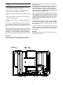
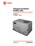
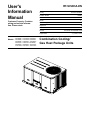
User's
Information
Manual
Customer Property: Contains
wiring and service information. Please retain
RT-SVU03A-EN
Library
Service Literature
Product Section
Unitary
Product
Rooftop Lt. Comm.
Model
Y_
Literature Type
User's Manual
Sequence
A
Date
File No.
December 2005
SV-UN-RT-SVU03A-EN 12/05
Supersedes
Y_C-UM-1 01/01
YSC036E*, YHC033A*,YHC036A*
Combination Cooling/
YSC060E*, YHC063A*, YHC060A*
YSC072A*, YHC072A* YSC090A*,
YSC092A*, YHC092A*, YSC102A*,
YHC102A*, YSC120A*, YHC120A*
Gas Heat Package Units
Models : YSC048E*, YHC043A*,YHC048A*
WARNING
Hazard of Explosion or Fire!
General Information
Overview
Your combination gas heating/electric cooling unit is designed to comfort condition all year long with safe, efficient,
trouble free operation. It is important that you understand
how to operate and maintain your unit to keep it operating
safely and efficiently. This manual will acquaint you with
these important procedures. Familiarize yourself with this
manual and store it in a convenient location for future reference.
Do not store or use gasoline or other flammable
vapors and liquids in the vicinity of this or any
other appliance.
WHAT TO DO IF YOU SMELL GAS
-Do not try to light any appliance.
-Do not touch any electrical switch.
-Do not use any phone in your building.
-Open windows and doors.
-Alert others and evacuate building immediately.
-From a phone outsided of the building, immediately
call your gas supplier. Follow the gas supplier's instructions.
-If you can not reach your gas supplier, call the
fire department.
Failure to follow the steps listed above could result in
death or serious injury or property damage.
Any additions, changes or conversions required in order
for the unit to satisfactorily meet the application needs
should be made by a qualified product distributor or local
service dealer, using factory specified and approved parts.
See figure 1 for component layout.
WARNING – Indicates a potentially
hazardous situation which, if not avoided, could
result in death or serious injury.
WARNING
Safety Hazard!
CAUTION – Indicates a potentially
hazardous situation which, if not avoided, may
result in minor or moderate injury. It may also be
used to alert against unsafe practices.
Do not use this furnace if any portion has been
under water. Immediately call a qualified service
technican to inspect the furnace and to replace any
part or the control system and any gas control
which has been under water. Unito or component
damage due to water could cause unit malcuntion
resulting in death or serious injury or equipment or
property damage.
CAUTION – Indicates a situation that may result
in equipment or property-damage-only accidents.
WARNING
Safety Hazard!
Should overheating occur, or the unit gas valve
fail to shut off, close the gas valve to the furnace
before shutting off the electrical supply. Failure to
close off the gas supply could result in death or
serious injury or severe equipment or property
damage.
2
IMPORTANT: Remember these instructions at all
times:
1. Never perform any maintenance procedures until the
electrical power to the unit is turned off.
2. Never perform any maintenance procedures until the
gas valve is the gas supply line is turned off.
3. Never remove any panels from the unit while it is operating.
4. Never remove panels or parts from the unit that are not
discussed in this manual.
5. Never cover the unit since it is designed to operate year
round.
Your unit is of complex design. To ensure that it performs
safely and gives long lasting services, some of the maintenance work must be performed by a qualified service person.
When a service person is referred to in this manual it is describing a service technician that has had special training
or a number of years experience in servicing this type of
equipment. It is your responsibility to select a qualified service company that can provide a service person of this caliber.
the heating or cooling circuit to maintain the temperature
setting you select.
Many thermostats contain a room thermometer to indicate
the approximate room temperature and a temperature
scale at the adjustment indicator to select the desired indoor air temperature. In addition, most thermostats have a
selector mode switch with Heat, Off and Cool positions and
a fan switch with On and Off positions.
When the switch is positioned at Off your unit will not operate in either the heat or cool modes. If the selector switch
is set at Heat the unit will automatically cycle on and off to
maintain the desired temperature setting. The unit will also
operate automatically when the selector switch is positioned at Cool.
The fan selector switch can be used to operate the indoor
fan continuously by positioning it at On. When set to Auto
the fan will only operate when required during the heating
or cooling cycles.
To ensure that the thermostat operates properly, it must be
level and positioned to avoid the influence of such external
heat sources and lamps, televisions or other heat producing appliances.
Air Filters
Filters are to be used with this unit. Units ship from the factory with filters installed.
Thermostat
Room thermostats are delicate temperature sensing controls. Their main function is to energize and de-energize
3
WARNING
Hazardous Voltage w/Capacitors!
Heating System
Heating Cycle Operation
Your unit's heating system has a solid-state electronic ignition control that lights the furnace burners each time the
thermostat calls for heat. At the end of each heating cycle
the furnace burners are extinguished. This type of system
is called Direct Spark Ignition (DSI).
Disconnect all electric power, including remote
disconnects and discharge all motor start/run
capacitors before servicing. Follow proper lockout/
tagout procedures to ensure the power cannot be
inadvertently energized. Verify with an appropriate
voltmeter that all capacitors have discharged.
Failure to disconnect power and discharge capacitors before servicing could result in death or
serious injury.
A normal heating cycle begins when the air temperature
drops below the thermostat setting. The thermostat then energizes the heating electrical circuit that starts and controls
the furnace burners. Shortly after the burners ignite the indoor fan starts and circulates warm air through the conditioned space.
It is very important to keep the central duct system air filters
clean. Be sure to inspect them at least once each month
when the systemis in constant operaton. (In new homes,
check the filters every week for the first 4 weeks.) See
Table 1 for the required filter size(s).
When the air temperature rises to the thermostat setting
the thermostat de-energizes the heating electrical circuit,
which in turn extinguishes the burners. The indoor fan continues to circulate warm air until most of the heat is removed from the unit's combustion chamber.
If you have disposable type filters, replace them with new
filters of the same type and size Do not attempt to clean
disposable filters.
Safety Controls
Your unit is equipped with an automatic reset safety limit
control to prevent overheating. When this control opens, it
shuts down the heating electrical circuit until the unit cools
down sufficiently. Inadequate airflow (i.e., caused by dirty
filters or defective fan motor) may cause the unit to cycle
on and off as the limit trips and automatically resets. If you
suspect that the unit is cycling on it's limit control, immediately contact a service person for instructions.
Permanent type filters can be cleaned by washing them
with a mild detergent and water. Ensure that the filters are
thoroughly dry before reinstalling them in the unit (or duct
system).
Note: It may be necessary to replace permanent
filters annually if washing fails to clean the filter, or to
use the same type and sizeas was originally
installed.
If flames from the burner are not properly drawn into the
heat exchanger, a Flame Rollout Protection Control will
open causing the furnace to shut off. The cause must be investigated by a qualified service person.
Table 1- Recommended Standard Filters
Unit Model
Number
Low Heat
Filter Size
Inches
Millimeters
YHC033*
(2) 20x25x1
(2) 508x635x25
YH/YSC036*
(2) 20x25x1
(2) 508x635x25
YHC043*
(2) 20x25x1
(2) 508x635x25
YH/YSC048*
(2) 20x25x1
(2) 508x635x25
YSC060A1,3,4,W (2) 20x25x1
(2) 508x635x25
YHC060A1,3,4,W (2) 20x30x1
(2) 508x762x25
YHC063*
(2) 20x30x1
(2) 508x762x25
YSC060*D,T
(2) 20x30x1
(2) 508x762x25
YH/YSC072*
(4) 16x25x2
(4) 406x635x50
YSC090*
(4) 16x25x2
(4) 406x635x50
YSC092*
(4) 16x25x2
(4) 406x635x50
YHC092*
(4) 20x25x2
(4) 508x635x50
YH/YSC102*
(4) 20x25x2
(4) 508x635x50
YH/YSC120*
(4) 20x25x2
(4) 508x635x50
Medium Heat
Filter Size
Inches
Millimeters
(2) 20x25x1
(2) 508x635x25
(2) 20x25x1
(2) 508x635x25
(2) 20x25x1
(2) 508x635x25
(2) 20x25x1
(2) 508x635x25
(2) 20x25x1
(2) 508x635x25
(2) 20x30x1
(2) 508x762x25
(2) 20x30x1
(2) 508x762x25
N/A
N/A
(4) 16x25x2
(4) 406x635x50
(4) 16x25x2
(4) 406x635x50
(4) 16x25x2
(4) 406x635x50
(4) 20x25x2
(4) 508x635x50
(4) 20x25x2
(4) 508x635x50
(4) 20x25x2
(4) 508x635x50
4
High Heat
Filter Size
Inches
Millimeters
(2) 20x30x1
(2) 508x762x25
(2) 20x30x1
(2) 508x762x25
(2) 20x30x1
(2) 508x762x25
(2) 20x30x1
(2) 508x762x25
(2) 20x30x1
(2) 508x762x25
(2) 20x30x1
(2) 508x762x25
(2) 20x30x1
(2) 508x762x25
(2) 20x30x1
(2) 508x762x25
(4) 16x25x2
(4) 406x635x50
(4) 16x25x2
(4) 406x635x50
(4) 16x25x2
(4) 406x635x50
(4) 20x25x2
(4) 508x635x50
(4) 20x25x2
(4) 508x635x50
(4) 20x25x2
(4) 508x635x50
Heating System Start-Up
Since your unit has an automatic ignition system, it is easy
to start the heating cycle at the beginning of the heating
season. In order for the unit to operate properly and safely,
the furnace needs air for both combustion and ventilation.
Check to make sure that all air openings are unobstructed
and there is adequate clearance around the unit to provide
good air flow.
1. Set the thermostat's heating adjustment lever at its lowest setting.
2. Move the selector switch to the Off position.
WARNING
Hazardous Voltage w/Capacitors!
Disconnect all electric power, including remote
disconnects and discharge all motor start/run
capacitors before servicing. Follow proper lockout/
tagout procedures to ensure the power cannot be
inadvertently energized. Verify with an appropriate
voltmeter that all capacitors have discharged.
Failure to disconnect power and discharge capacitors before servicing could result in death or
serious injury.
3. Turn off all electric power to the unit.
4. This unit is equipped with an ignition device which automatically lights the burners.
Important : The unit is to be adjusted to obtain an air
rise within that specified on the nameplate.
Heating System Shutdown
To shut down the heating system for brief periods of time
simply adjust the thermostat selector switch to the "Off" position.
To Turn Off Gas To Unit
1. Set the thermostat to lowest setting.
WARNING
Hazardous Voltage w/Capacitors!
Disconnect all electric power, including remote
disconnects and discharge all motor start/run
capacitors before servicing. Follow proper lockout/
tagout procedures to ensure the power cannot be
inadvertently energized. Verify with an appropriate
voltmeter that all capacitors have discharged.
Failure to disconnect power and discharge capacitors before servicing could result in death or
serious injury.
2. Turn off all electric power to the unit if service is to be
performed.
3. Remove the access panel that contains the following label:
REMOVE THIS PANEL TO GAIN
ACCESS TO THE GAS VALVE
Caution : Never attempt to manually light the burner.
5. Remove the access panel that contains the following label.
REMOVE THIS PANEL TO GAIN
ACCESS TO THE GAS VALVE
4. Turn gas control knob clockwise to the "OFF" position.
5. Replace panel removed in step 3 above.
6. Turn gas control knob clockwise to the "OFF position.
Note: Some valves require the knob to be pushed in
slightly before turning.
7. Wait (5) minutes to clear out any gas. If you then smell
gas, STOP! Follow "For Your Safety", "What To Do If
You Smell Gas" instructions on the second page. If you
do not smell gas, go to the next step.
8. Turn gas control knob counterclockwise to the ON position.
9. Replace panel removed in step 4 above.
10. Turn on all electric power to unit.
11. Set thermostat to desired temperature and move the
selector switch to the ON position. The unit will now operate automatically.
12. If the unit will not operate, follow the instructions "To
Turn Off Gas To Unit" (under Heating System Shutdown) and call your service technician or gas supplier.
© American Standard 2005
Technical Literature Printed in USA
5
CAUTION
Property Damage!
IMPORTANT: Refer to warining on page 2 regarding
comustible materials and what to do if you smell
gass.
If this is done during the cold weather months,
provisions must be taken to prevent freeze-up of
all water pipes and water receptacles.. Whenever
your house or building is to be vacant, arrange to
have someone inspect your structure for proper
temperature. This is very important in below freezing weather. If for any reason your furnace should
fail to operate, damage such as frozen water pipes
could result.
These steps should only be performed by a qualified
service technician.
1. Inspect the control panl wiring and heating controls to
make sure connections are tight and wiring insulation is
intact.
2. Turn the unit on and off at the thermostat to be sure the
ignition control and spark electrode are operating properly.
Heating System Maintenance
Complete the following unit inspections and service routines at the beginning of each heating season.
3. Turn off the gas supply with the unit operating to verfiy
that the gas valves closes and that a re-ignition cycle is
initiated by the ignition control.
WARNING
Hazardous Service Procedures!
The maintenance and troubleshooting procedures
recommended in this section of the manual could
result in exposure to electrical, mechanical or other
potential safety hazards. Always refer to the safety
warnings provided throughout this manual concerning these procedures. When possible, disconnect all electrical power including remote disconnect and discharge all energy storing devices such
as capacitors before servicing. Follow proper
lockout/tagout procedures to ensure the power can
not be inadvertently energized. When necessary to
work with live electrical components, have a
qualified licensed electrician or other individual
who has been trained in handling live electrical
components perform these tasks. Failure to follow
all of the recommended safety warnings provided,
could result in death or serious injury.
4. Check the operation of the gas ignition system.
5. Check the burner manifold manifold pressure. a 1/8 inch
pipe plug is provided in the gas valve for this purpose.
6. Visually inspect all of the unit's flue product passage
ways for excessive deposit build up and corrosion. If
build up or corrosion is appparent, perform the necessary repairs.
7. Arrange for a qualified serviceman to inspect the unit every other heating season to maintain safe and efficient
operation.
8. Visually check the main burner flames. They should be
bright blue flames extending into the heat exchanger
sections.
9. Never store anything fammable or combustible around
or near the unit.
6
7
8