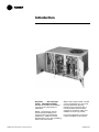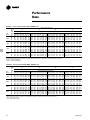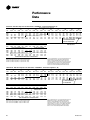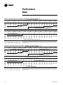
1
Packaged Gas/Electric
Rooftop Units
Precedent™
YSC060-120
50 Hz
February 2004
RT-PRC017-EN
Introduction
Precedent™ . . . The same Trane
quality... with added flexibility.
Precedent is a flexible line of packaged
units that covers a wide variety of
applications.
Reliatel™ microprocessor controls
provide superior flexibility for the
simplest to the most sophisticated
applications. In addition to controls,
Precedent offers many other outstanding
features and option choices.
© 2004 American Standard Inc. All rights reserved
With its sleek compact cabinet, rounded
corners and beveled top, it may just be
the most aesthetically pleasing
packaged unit on the planet. And, of
course, Precedent carries the Trane
reputation for excellence, quality, and
reliability. It’s hard to stop a Trane.
From simple applications, to the most
complex, Precedent has the solution.
RT-PRC017-EN
Contents
RT-PRC017-EN
Introduction
Features and Benefits
2
Application Considerations
9
4
Selection Procedure
10
Model Number Description
12
General Data
13
Performance Data
14
Zone Controls
42
Electrical Data
43
Jobsite Connection
44
Dimensional Data
45
Weights
53
Mechanical Specifications
54
3
Features and
Benefits
Easy Access Panels
Remove two screws for access to the
standardized internal components and
wiring.
Easy-Adjust Idler Arm
With the Easy-Adjust Idler Arm, the belt
and sheaves can be quickly adjusted
without moving the mounted fan motor.
The result is a major savings in time and
money.
Patented Condenser Coil
Precedent boasts a patented 1+1+1
Hybrid coil, permanently gapped for
easy cleaning.
Unit Cabinet
The compact cabinet with rounded
corners takes up less room and is less
costly to ship. The beveled and ribbed
top is not only aesthetically pleasing, it is
designed to prevent water from pooling.
Single Point Power
A single electrical connection powers the
unit.
Colored And Numbered Wiring
You save time and money tracing wires
and diagnosing the unit.
Convertible Units
• The units ship in a downflow
configuration. They can be easily
converted to horizontal by simply
moving two panels.
Compressors
Precedent™ contains the best
compressor technology available to
achieve the highest possible
performance. Our compressor line
includes Trane built Climatuff™
reciprocating and scrolls.
• Units come complete with horizontal
duct flanges so the contractor doesn’t
have to field fabricate them. These
duct flanges are a time and cost saver.
Sloped Drain Pans
Every Precedent unit has a noncorrosive, removable, double-sloped
drain pan that’s easy to clean and
reversible to allow installation of drain
trap on either side of the unit.
Through the Base Condensate
Every unit includes provisions for
through the base condensate drain
connections. This allows the drain to be
connected through the roof curb instead
of a roof penetration.
Foil-Faced Insulation
All panels in the Evaporator section of
the unit have cleanable foil-faced
insulation. All edges are either captured
or sealed to ensure no fibers get into the
airstream.
Easy Access Panels
Easy access panels reduce the number of
possible water entry points.
Low Ambient Cooling
All Precedent units have cooling
capabilities down to -18°C (0°F) as
standard.
Unit Base
For added water integrity, Precedent has
a raised 29 mm (11/8") lip around the
unit’s downflow supply and return to
prevent water from blowing into the
ductwork.
4
RT-PRC017-EN
Features and
Benefits
Standardized Components
• Components are placed in the same
location on all Precedent™ units.
Familiarize yourself with one Precedent
and you are familiar with every
Precedent.
Easy Access Low Voltage Terminal
Board
Precedent’s Low Voltage Terminal Board
is external to the electrical control
cabinet. It is extremely easy to test
operation of all unit functions. This is
another cost and time saving installation
feature.
Progressive Tubular Heat Exchanger
The compact cabinet features a tubular
heat exchanger in low, medium and high
heat capacities.
The heat exchanger is fabricated using
stainless steel burners and corrosionresistant aluminized steel tubes as
standard on all models. It has an induced
draft blower to pull the gas mixture
through the burner tubes. The heater
has a direct spark ignition system which
doubles as a safety device to prove the
flame.
Flexible Applications
• Only two roof curbs for the 5-10 ton
Precedent line. . .simplifies curb
selection.
• ReliaTel microprocessor controls to
meet either the simple or the more
complex application.
• Low or high gas heat capacities.
• Airflow is outstanding. The Precedent
can replace an older machine with old
ductwork and, in many cases, improve
comfort through better air distribution.
• Belt drive —standard or oversized
supply fan motors meet a wide airflow
range.
• Precedent offers ultimate flexibility.
Options and components are not prepackaged at the factory. Units are built
to order in our standard “shortest in
the industry”ship cycle time.
Low Voltage Connections
The wiring of the low voltage
connections to the unit and the zone
sensors is as simple as 1-1, 2-2, and 3-3.
This simplified system makes it easy for
the installer to wire.
Single-Side Service
Single-side service is standard on all
Precedent units.
RT-PRC017-EN
5
Features and
Benefits
• Eliminates the need for field-installed
components with its built-in anti-shortcycle timer, time delay relay and
minimum ‘’on’’ time controls. These
controls are factory tested to assure
proper operation.
Micro Controls
Several years ago, Trane was the first to
introduce microprocessor controls into
the Light Commercial Market. That
design, along with immeasurable
experience, has provided the technology
for Trane’s second-generation ReliaTel™
microprocessor controls.
ReliaTel Micro:
• Provides unit control for heating,
cooling, and ventilating by utilizing
input from sensors that measure
outdoor and indoor temperature.
• As long as the unit has power and the
LED is lit, the Micro is operational. The
light indicates that the Micro is
functioning properly.
• Features expanded diagnostic
capabilities when used with Trane’s
Integrated Comfort™ Systems.
• Improves quality and reliability
through the use of time-tested
microprocessor controls and logic.
• As an energy benefit, softens electrical
‘’spikes’’ by staging on fans,
compressors and heaters.
• Prevents the unit from short cycling,
considerably improving compressor
life.
• The Intelligent Fallback or Adaptive
Control is a benefit to the building
occupant. If a component goes astray,
the unit will continue to operate at
predetermined temperature set points.
• Ensures that the compressor will run
for a specific amount of time, which
allows oil to return for better
lubrication, enhancing the reliability of
the compressor.
• Reduces the number of components
required to operate the unit, thereby
reducing possibilities for component
failure.
6
• Requires no special tools to run the
Precedent unit through its paces
during testing. Simply place a jumper
between Test 1 and Test 2 terminals on
the Low Voltage Terminal Board and
the unit will walk through its
operational steps. The unit
automatically returns control to the
zone sensor after stepping through the
test mode a single time, even if the
jumper is left on the unit.
• Intelligent Anticipation is a standard
feature of the Micro. Functioning
constantly, the Micro and zone sensors
work together in harmony, to provide
tight comfort control.
RT-PRC017-EN
Features and
Benefits
Factory-installed Options
Hinged Access Doors
These doors permit easy access to the
filter, fan/heat, and compressor/control
sections. They reduce the potential roof
damage from screws or sharp access
door corners.
The following options round-out the
complete line of Precedent™ options:
Economizer
Equipped with either dry bulb, reference
or comparative enthalpy sensing, this
feature provides free cooling as the
outdoor temperature and/or humidity
decreases. Economizers, correctly
installed, offer valuable energy savings.
Factory-installed economizers save time
and ensure proper installation.
— Hail Protection Quality Coil Guards
Phase Monitor
Phase monitor shall provide 100%
protection for motors and compressors
against problems caused by phase loss,
phase imbalance, and phase reversal.
Phase monitor is equipped with an LED
that provides an ON or FAULT indicator.
Clogged Filter/Fan Fail Switches
These sensors allow a zone sensor
service light or Integrated Comfort
System to indicate a dirty filter or a fan
that’s not working. The field installation
charges for these valuable feedback
devices often eliminate them from
consideration. Factory installation can
make such features a good investment.
— 0 - 50% Manual or Motorized
Outside Air
— Discharge Air Sensor
— Wide array of Zone Sensors and
Thermostats
— Liquid Propane Conversion Kits
— Factory built Roof Curb
One of Our Finest Assets:
Trane Sales Representatives are a
Support group that can assist you with:
— Product
— Application
— Service
— Training
— Special Applications
— Specifications
— Computer Programs and much more
Precedent has the features and benefits
that make it first class in the light
commercial rooftop market. Designed
with input from field contractors and
engineers, its airflow performance is
outstanding.
Precedent…The same Trane
quality…with added flexibility.
COMM3/4 Communication Interface
Available factory or field-installed. This
module, when applied with ReliaTel™,
easily interfaces with Trane’s Integrated
Comfort™ System.
RT-PRC017-EN
7
Features and
Benefits
Quality And Reliability Testing
™
• All Precedent designs were rigorously
rain tested at the factory to ensure
water integrity.
• Actual shipping tests were performed
to determine packaging requirements.
Units were test shipped around the
country to determine the best
packaging.
• Factory shake and drop tests were
used as part of the package design
process to help assure that the unit
arrives at the job site in top condition.
• Rigging tests include lifting a unit into
the air and letting it drop one foot,
assuring that the lifting lugs and rails
hold up under stress.
• We perform a 100% coil leak test at the
factory. The evaporator and condenser
coils are leak tested at 1375 kPa (200
psig) and pressure tested to 3100 kPa
(450 psig).
• All parts are inspected at the point of
final assembly. Sub-standard parts are
identified and rejected immediately.
• The requirement for cycle testing of
heat exchangers is 10,000 cycles by
ANSI Z21.47. This is the standard
required by both UL and AGA for cycle
test requirments. Trane requires the
design to be tested to 2½ times this
current standard.
• Every unit receives a 100% unit run test
before leaving the production line to
make sure it lives up to rigorous Trane
requirements.
We test designs at our factory not on
our customers!
VariTrac™
VariTrac
When Trane’s changeover VAV System
for light commercial applications is
coupled with Precedent, it provides the
latest in technological advances for
comfort management systems and can
allow thermostat control in every zone
served by VariTrac.
8
RT-PRC017-EN
Application
Considerations
Application of this product should be
within the cataloged airflow and cooling
considerations.
Low Ambient Cooling
The Precedent™ line features, as
standard, low ambient cooling down to
-18°C (0°F). Contact your local Trane
Representative for more assistance with
low ambient cooling applications.
Barometric Relief
This product offers an optional
barometric relief damper for use in
conjunction with economizer option.
This option consists of gravity dampers
which open with increased pressure. As
the building air pressure increases, the
pressure in the unit return air section
also increases, opening the dampers and
relieving the conditioned space.
NOTE: THE EFFECTIVENESS OF
BAROMETRIC RELIEF DAMPER DURING
ECONOMIZING OPERATION IS SYSTEM
RELATED. PRESSURE DROP OF THE
RETURN AIR SYSTEM SHOULD BE
CONSIDERED TO CONTROL BUILDING
PRESSURIZATION.
RT-PRC017-EN
Heating Operation
The heat exchanger is manufactured
with aluminized steel. To prevent
condensation within the heat exchanger,
do not exceed 50% outside air.
Condensate Trap
The evaporator is a draw-thru
configuration. A trap must be field
provided prior to start-up on the cooling
cycle.
Clearance Requirements
The recommended clearances identified
with unit dimensions should be
maintained to assure adequate service,
maximum capacity and peak operating
efficiency. Actual clearances which
appear inadequate should be reviewed
with the local Trane sales personnel.
Unit Pitch
These units have reversible sloped
condensate drain pans. Units must be
installed level; any unit slope must be
toward side of unit where condensate
drain is connected.
9
Selection
Procedures - SI Units
Cooling Capacity
Heating Capacity
Step 1 — Calculate the building’s total
and sensible cooling loads at design
conditions. Use the Trane calculation
form or any other standard accepted
method.
Step 1 — Calculate the building heating
load using the Trane calculation form or
other standard accepted method.
Example: The following are the building
cooling requirements:
a. Electrical Characteristics: 380-415/50/3
b. Summer Design Conditions: Entering
Evaporator Coil: 27° DB/ 19° WB
Outdoor Ambient: 35°
c. Total Cooling Load: 16.5 kW
d. Sensible Cooling Load: 11.8 kW
e. Airflow: 3400 m3/h External Static
Pressure: 125 Pa
f. Downflow Configuration
Step 2 — Size the equipment using Table
PD-1 to match the cooling loads at
design conditions.
Table PD-1 shows that a YSC060AD has
a gross cooling capacity of 17.8 kW and
14.4 kW sensible capacity at 35 DB
ambient and 3400 m3/h with 27 DB/ 19
WB air entering the evaporator.
Use the following formula to calculate
fan motor heat, which can be found in
the notes in Table PD-8:
Fan motor heat (kW)
= 1.144 x (Fan kW) + 0.132
Step 2 — Size the system heating
capacity to match the calculated
building heating load. The following
are building heating requirements:
a. Total heating load of 17.6 kW
b. 3400 m3/h
c. Fuel - Natural gas
For the YSC060AD there are two
heating capacities available, 19.6 kW
and 29.3 kW input models shown in
Table PD-32. The output capacities of
these furnaces are 15.7 kW and 23.4 kW
respectively. The high heat model with
23.4 kW best matches the building
requirements, indicating a YHC060AD*
should be selected.
Air Delivery Selection
External static pressure drop through
the air distribution system has been
calculated to be 150 Pa. Enter Table PD8 for a YSC060AD*H at 3400 m3/h and
150 Pa static pressure. The standard
motor will give the desired airflow.
Accessory Selection
Select accessories needed to
accommodate the application.
For example: With 3400 m3/h and 125 Pa,
specified by the engineer, Table PD-8
shows 0.73 kW for a high heat model.
Fan motor heat =
1.144 x 0.73 + 0.132 = 0.97kW
Net Total Cooling =
17.8 kW - 0.97 = 16.8 kW
Net Sensible Cooling Capacity
14.4 kW - 0.97 = 13.4 kW.
10
RT-PRC017-EN
Selection
Procedures - IP Units
Cooling Capacity
Heating Capacity
Step 1 — Calculate the building’s total
and sensible cooling loads at design
conditions. Use the Trane calculation
form or any other standard accepted
method.
Step 1 — Calculate the building heating
load using the Trane calculation form or
other standard accepted method.
Example: The following are the building
cooling requirements:
a. Electrical Characteristics: 380-415/50/3
b. Summer Design Conditions: Entering
Evaporator Coil: 80° DB/ 67° WB
Outdoor Ambient: 95°
c. Total Cooling Load: 58 MBh
d. Sensible Cooling Load: 42 MBh
e. Airflow: 2000 cfm External Static
Pressure: .6 in wg
f. Downflow Configuration
Step 2 — Size the equipment using Table
PD-1a to match the cooling loads at
design conditions.
Table PD-1a shows that a YSC060AD has
a gross cooling capacity of 62.0 MBh and
46.4 MBh sensible capacity at 95 DB
ambient and 2000 cfm with 80 DB/ 67
WB air entering the evaporator.
Use the following formula to calculate
fan motor heat, which can be found in
the notes in Table PD-8a:
Fan motor heat (MBh) =
2.915 x (Fan bhp) + 0.451
For example: With 2000 cfm and 0.60
inches, specified by the engineer, Table
PD-8a shows 1.06 bhp for a high heat
model.
Step 2 — Size the system heating
capacity to match the calculated building
heating load. The following are building
heating requirements:
a. Total heating load of 70.0 MBh
b. 2000 cfm
c. Fuel - Natural gas
For the YSC060AD there are two heating
capacities available, 67 MBh and 100
MBh input models shown in Table PD32. The output capacities of these
furnaces are 54 MBh and 80 MBh
respectively. The high heat model with
80 MBh best matches the building
requirements, indicating a YSC060AD*H
should be selected.
Air Delivery Selection
External static pressure drop through the
air distribution system has been
calculated to be 0.6 inches of water. Enter
Table PD-8a for a YSC060AD*H at 2000
cfm and 0.60 static pressure. The
standard motor will give the desired
airflow.
Accessory Selection
Select accessories needed to
accommodate the application.
Fan motor heat =
2.915 x 1.06 + 0.451 = 3.5 MBh
Net Total Cooling =
62.0 MBh - 3.5 = 58.5 MBh
Net Sensible Cooling Capacity
46.4 MBh - 3.5 = 42.9 MBh.
RT-PRC017-EN
11
Model
Number
Description
Y S
C 060 A
D
R
L
1
3 4,5,6 7
8
9
10 11 12,13 14 15 16 17
2
A
**
C
0
0
0
0
0
0
0
18 19 20 21
0
0
0
1
22 23 24 25
Digit 1 - Unit Function
Y = DX Cooling, Gas Heat
Digits 12, 13 - Service Sequence
** =
Factory Assigned
Digit 18 - Through the Base Provisions
0 = No Through the Base Provisions
Digit 2 - Efficiency
S = Standard Efficiency
Digit 14 - Fresh Air Selection
0 = No Fresh Air
A = Manual Outside Air Damper 0-50%
B = Motorized Outside Air Damper 0-50%
C = Economizer, Dry Bulb 0-100%
without Barometric Relief
D = Economizer, Dry Bulb 0-100%
with Barometric Relief
E = Economizer, Reference Enthalpy
0-100% without Barometric Relief
F = Economizer, Reference Enthalpy
0-100% with Barometric Relief
G = Economizer, Comparative Enthalpy
0-100% without Barometric Relief
H = Economizer, Comparative Enthalpy
0-100% with Barometric Relief
Digit 19 - Disconnect/Circuit Breaker/Phase
Monitor (3 phase only)
0 = No Disconnect or Circuit Breaker
3 = Phase Monitor Only (No Disconnect,
No Circuit Breaker)
Digit 3 - Airflow
C = Convertible
Digits 4,5,6 - Nominal Gross Cooling
Capacity (MBh)
kW
Tons
060 = 17.6
5
072 = 21.1
6
090 = 26.4
7.5
102 = 29.9
8.5
120 = 35.1
10
Digit 7 - Major Design Sequence
A = First
Digit 8 - Unit Voltage
D = 380-415/50/3
Digit 9 - Unit Controls
R = ReliaTel™ Microprocessor
Digit 10 - Heating Capacity
L = Low
H = High
Digit 11 - Minor Design Sequence
A = First Sequence
12
Digit 15 - Supply Fan/Drive Type/Motor
0 = Standard Drive
1 = Oversized Motor
Digit 16 - Hinged Service AccessFilters
0 = Standard Panels/Standard Filters
A = Hinged Access Panels/Standard Filters
B = Standard Panels/50 mm (2”)
Pleated Filters
C = Hinged Access Panels/50 mm 2”
Pleated Filters
Digit 17 - Condenser Coil Protection
0 = Standard Coil
1 = Standard Coil with Hail Guard
2 = Epoxy Coated Condenser Coil
3 = Epoxy Coated Condenser Coil with
Hail Guard
Digit 20 - Convenience Outlet
0 = No Convenience Outlet
Digit 21 - Communications Options
0 = No Communications Interface
1 = Comm-3/4 Communications Interface
2 = Comm-5 Communications Interface
Digit 22 - Refrigeration System Option
0 = Standard Refrigeration System
Digit 23 - Refrigeration Controls
0 = No Refrigeration Control
Digit 24 - Smoke Detector
0 = No Smoke Detector
Digit 25 - Monitoring Controls
0 = No Monitoring Control
1 = Clogged Filter Switch
2 = Fan Failure Switch
3 = DischargeAir Sensing Tube
4 = Clogged Filter Switch and Fan Fail
Switch
5 = Clogged Filter Switch and Discharge
Air Sensing Tube
6 = Fan Fail Switch and Discharge Air
Sensing Tube
7 = Clogged Filter and Fan Fail Switches
and Discharge Air Sensing Tube
RT-PRC017-EN
General Data
Table GD-1 — General Data
Cooling Performance 1
Gross Capacity - kW (MBh)
COP (EER) 2
Nominal Airflow - m3/h (cfm)
Rated Airflow - m3/h (cfm)
Net Capacity - kW (MBh)
System Power - kW
Heating Performance 3
Heating Models
Heating Input - kW (MBH)
Heating Output - kW (MBH)
Steady State Efficiency %
No. Burners
No. Stages
Gas Connection Pipe Size - in.
Compressor
Number - Type
Outdoor Sound Rating dB 4
Outdoor Coil - Type
Tube Size in. OD
Face Area - m2 (sq ft)
Rows / FPI
Indoor Coil - Type
Tube Size OD - in.
Face Area - m2 (sq ft)
Rows / FPI
Refrigerant Control
Drain Connection No. / Size - in.
Outdoor Fan - Type
No. Used / Diameter - in.
Drive Type / No. Speeds
CFM
No. Motors / kW (HP)
Motor RPM
Belt Drive Indoor Fan - Type
No. Used
Fan Diameter x Width - mm (in.)
Drvie Type / No. Speeds
No. Motors
Standard Motor Power - kW (HP)
Oversized Motor Power - kW (HP)
Motor RPM - Standard / Oversized
Motor Frame Size
Filters - Type Furnished
(No.) Size Reccommended - mm
(No.) Size Reccommended - in.
Refrigerant Charge - kg (lbs) of R-22 5
Convertible Units
YSC060AD
Convertible Units
YSC072AD
Convertible Units
YSC090AD
Convertible Units
YSC102AD
Convertible Units
YSC120AD
18.2 (62.0)
2.99 (10.2)
3400 (2000)
3400 (2000)
17.3 (59.0)
5.78
23.2 (79.0)
3.08 (10.5)
4080 (2400)
3570 (2100)
22.0 (75.0)
7.14
26.7 (91.0)
3.02 (10.3)
5100 (3000)
4460 (2625)
25.2 (86.0)
8.35
31.1 (106.0)
3.02 (10.3)
5780 (3400)
5100 (3000)
29.9 (102.0)
9.9
34.9 (119.0)
2.99 (10.2)
6800 (4000)
5950 (3500)
33.1 (113.0)
11.08
Low - G80
19.6 (67)
15.7 (54)
90
2
1
3/4 NPT
High - G120
29.3 (100)
23.4 (80)
90
3
1
3/4 NPT
1-Climatuff Scroll
80
Lanced
0.3125
1.02 (10.96)
3 / 17
Lanced
0.3125
0.62 (6.68)
3 / 16
Short Orifice
1 / 0.75 NPT
Propeller
1 / 22
Direct / 1
2900
1 / 0.30 (0.40)
950
FC Centrifugal
1
280 X 280 (11 x 11)
Belt / Variable Speed
1
1.1 (1.5)
1450 / 56
Throwaway
(2) 508 X 762 X 25
(2) 20 X 30 X 1
3.7 (8.2)
Low - G120 High G-200
29.3 (100) 48.9 (167)
23.4 (80)
39.1 (134)
90
90
3
4
1
2
3/4 NPT
3/4 NPT
1-Trane 3-D Scroll
85
Lanced
0.3125
1.29 (13.88)
2 / 17
Lanced
0.3125
0.92 (9.89)
2 / 16
Short Orifice
1 / 0.75 NPT
Propeller
1 / 26
Direct / 1
5100
1 / .56 (0.75)
950
FC Centrifugal
1
305 X 305 (12 x 12)
Belt / Variable Speed
1
1.1 (1.5)
1.5 (2.0)
1450 / 1450
56
Throwaway
(4) 406 X 635 X 50
(4) 16 X 25 X 2
3.7 (8.2)
Low - G120
29.3 (100)
23.4 (80)
90
3
1
3/4 NPT
High G-200
48.9 (167)
39.1 (134)
90
4
2
3/4 NPT
1-Trane 3-D Scroll
85
Lanced
0.3125
1.29 (13.88)
2 / 17
Lanced
0.3125
0.92 (9.89)
3 / 16
Short Orifice
1 / 0.75 NPT
Propeller
1 / 26
Direct / 1
5200
1 / .56 (0.75)
950
FC Centrifugal
1
305 X 305 (12 x 12)
Belt / Variable Speed
1
1.5 (2.0)
2.2 (3.0)
1450 / 2850
56
Throwaway
(4) 406 X 635 X 50
(4) 16 X 25 X 2
4.5 (10.0)
Low - G150 High G-250 Low - G150
36.7 (125) 60.9 (208) 36.7 (125)
29.3 (100) 48.7 (166) 29.3 (100)
90
90
90
3
5
3
2
2
2
3/4 NPT
3/4 NPT
3/4 NPT
2-Climatuff Scroll
83
Lanced
0.3125
1.75 (18.89)
2 / 17
Lanced
0.3125
1.15 (12.36)
3 / 16
Short Orifice
1 / 0.75 NPT
Propeller
1 / 26
Direct / 1
5500
1 / .56 (0.75)
950
FC Centrifugal
1
381 X 381 (15 x 15)
Belt / Variable Speed
1
1.5 (2.0)
2.2 (3.0)
1450 / 2850
56
Throwaway
(4) 508 X 635 X 50
(4) 20 X 25 X 2
Circuit 1 - 3.8 (8.3)
Circuit 2 - 2.0 (4.4)
High G-250
60.9 (208)
48.7 (166)
90
5
2
3/4 NPT
2-Climatuff Scroll
79
Lanced
0.3125
2.41 (25.92)
2 / 17
Lanced
0.3125
1.15 (12.36)
4 / 16
Short Orifice
1 / 0.75 NPT
Propeller
1 / 26
Direct / 1
5800
1 / .56 (0.75)
950
FC Centrifugal
1
381 X 381 (15 x 15)
Belt / Variable Speed
1
2.2 (3.0)
2850 / 56
Throwaway
(4) 508 X 635 X 50
(4) 20 X 25 X 2
Circuit 1 - 3.4 (7.5)
Circuit 2 - 3.3 (7.3)
Notes:
1. Cooling Performance is rated at 35.0 C (95 F) ambient, 26.7 C (80 F) entering dry bulb, 19.4 C (67 F) entering wet bulb. Gross capacity does not include the effect of fan motor
heat. Net capacity includes the effect of fan motor heat. Units are suitable for operation to ± 20 % of nominal airflow.
2. EER are rated at ARI conditions.
3. Heating Performance limit settings and rating data were established and approved under laboratory test conditions using American National Standards Institute standards.
Ratings shown are for elevations up to 2000 feet. For elevations above 2000 feet, ratings should be reduced at the rate of 4% for each 1000 feet above sea level.
4. Outdoor Sound rating shown is tested in accordance with ARI Standard 270. For more information refer to Performance Data Table "Sound Power Level".
5. Refrigerant charge is an approcimate value. For a more precise value, see unit nameplate and service literature.
RT-PRC017-EN
13
Performance
Data
Table PD-1 — Gross Cooling Capacities (kW) - YSC060AD - (SI)
Ambient Temperature (C)
m3/h
Airflow
3060
3400
3740
4080
Enter.
Dry
Bulb
Temp
(C)
24
27
30
33
24
27
30
33
24
27
30
33
24
27
30
33
30
35
40
45
Entering Wet Bulb Temperature (C)
16
19
22
16
19
22
16
19
22
16
19
22
TGC SHC TGC SHC TGC SHC TGC SHC TGC SHC TGC SHC TGC SHC TGC SHC TGC SHC TGC SHC TGC SHC TGC SHC
16.2 13.9 18.5 11.3 19.9 8.3 15.0 13.3 17.4 11.3 19.3 8.0 13.9 12.7 16.1 10.7 18.4 7.5 12.7 12.1 14.7 9.5 17.3 7.0
16.7 16.7 18.6 14.1 20.0 11.1 15.8 15.8 17.4 13.6 19.4 10.8 14.8 14.8 16.1 13.0 18.5 10.3 13.8 13.8 14.7 12.3 17.3 9.8
18.1 18.1 18.7 16.9 20.2 13.6 17.2 17.2 17.7 16.5 19.5 13.5 16.2 16.2 16.5 15.9 18.5 13.1 15.1 15.1 15.1 15.1 17.3 12.6
19.3 19.3 19.2 19.2 20.3 16.2 18.5 18.5 18.5 18.5 19.6 16.1 17.6 17.6 17.6 17.6 18.7 15.9 16.6 16.6 16.6 16.6 17.5 15.4
16.7 14.8 18.8 11.8 20.1 8.6 15.5 14.2 17.8 11.3 19.5 8.3 14.2 13.5 16.5 11.4 18.7 7.7 13.1 12.9 15.0 10.8 17.6 7.2
17.5 17.5 18.9 14.9 20.2 11.4 16.5 16.5 17.8 14.4 19.6 11.2 15.4 15.4 16.5 13.8 18.8 10.8 14.4 14.4 15.1 13.1 17.6 10.3
18.8 18.8 19.1 17.9 20.4 14.1 17.9 17.9 18.2 17.6 19.7 14.1 16.9 16.9 17.0 17.0 18.8 13.8 15.8 15.8 15.8 15.8 17.7 13.4
19.8 19.8 19.8 19.8 20.6 16.8 19.2 19.2 19.2 19.2 19.9 16.9 18.3 18.3 18.3 18.3 19.0 16.8 17.4 17.4 17.4 17.4 17.9 16.4
17.1 15.6 19.1 12.3 20.2 8.8 15.9 15.0 18.1 11.8 19.7 8.5 14.6 14.3 16.8 11.2 18.9 7.9 13.4 13.4 15.3 11.4 17.8 7.5
18.1 18.1 19.2 15.5 20.4 11.6 17.1 17.1 18.2 15.1 19.8 11.5 16.0 16.0 16.9 14.6 19.0 11.3 14.9 14.9 15.4 13.9 17.9 10.8
19.3 19.3 19.5 18.7 20.6 14.5 18.5 18.5 18.6 18.6 20.0 14.6 17.6 17.6 17.6 17.6 19.1 14.4 16.5 16.5 16.5 16.5 17.9 14.1
20.2 20.2 20.2 20.2 20.8 17.4 19.6 19.6 19.6 19.6 20.2 17.6 18.9 18.9 18.9 18.9 19.3 17.6 18.0 18.0 18.0 18.0 18.3 17.4
17.4 16.4 19.3 12.6 20.3 9.1 16.2 15.8 18.4 12.2 19.8 8.8 14.9 14.9 17.1 11.7 19.0 8.1 13.9 13.9 15.5 12.1 18.0 7.7
18.6 18.6 19.4 16.1 20.5 12.3 17.7 17.7 18.4 15.8 19.9 11.8 16.6 16.6 17.2 15.3 19.1 11.6 15.4 15.4 15.8 14.6 18.1 11.2
19.7 19.7 19.7 19.4 20.7 14.9 19.0 19.0 19.0 19.0 20.1 15.0 18.1 18.1 18.1 18.1 19.3 15.0 17.1 17.1 17.1 17.1 18.2 14.7
20.5 20.5 20.5 20.5 20.9 17.9 20.0 20.0 20.0 20.0 20.4 18.2 19.3 19.3 19.3 19.3 19.5 18.3 18.4 18.4 18.4 18.4 18.6 18.2
Notes:
1. All capacities shown are gross and have not considered indoor fan heat. To obtain net cooling, subtract indoor fan heat.
2. TGC = Total Gross Capacity
3. SHC = Sensible Heat Capacity
Table PD-1a _ Gross Cooling Capacities (MBH) _ YSC060AD _ (IP)
Ambient Temperature (F)
CFM
Airflow
1800
2000
2200
2400
Enter.
Dry
Bulb
Temp
(F)
75
80
85
90
75
80
85
90
75
80
85
90
75
80
85
90
85
95
105
115
Entering Wet Bulb Temperature (F)
61
67
73
61
67
73
61
67
73
61
67
73
TGC SHC TGC SHC TGC SHC TGC SHC TGC SHC TGC SHC TGC SHC TGC SHC TGC SHC TGC SHC TGC SHC TGC SHC
56.1 47.1 64.4 37.0 68.8 25.1 51.6 44.7 60.6 36.7 66.9 23.9 47.0 42.4 55.6 34.5 64.0 22.6 42.4 40.1 50.2 30.3 60.0 20.8
57.3 56.5 64.6 45.8 69.3 34.2 53.3 53.3 60.7 43.9 67.3 32.9 49.5 49.5 55.7 41.6 64.2 31.4 45.7 45.7 50.4 39.2 60.1 29.6
61.3 61.3 64.9 54.5 69.7 42.0 57.7 57.7 61.0 52.9 67.6 41.4 53.9 53.9 56.3 50.7 64.4 40.3 50.0 50.0 51.2 48.3 60.2 38.4
65.0 65.0 65.8 63.3 70.4 49.7 62.1 62.1 62.4 62.2 68.0 49.7 58.5 58.5 58.5 58.5 64.6 48.8 54.4 54.4 54.4 54.4 60.3 47.2
57.5 49.8 65.4 38.5 69.3 25.5 53.0 47.5 61.8 38.7 67.5 24.4 48.3 45.1 56.9 36.6 64.7 23.0 43.7 42.8 51.3 34.2 60.9 21.4
59.3 59.3 65.6 47.9 69.8 35.4 55.7 55.7 62.0 46.4 68.0 34.2 51.6 51.6 57.1 44.1 65.0 32.7 47.7 47.7 51.5 41.6 61.0 30.9
63.6 63.6 66.0 57.3 70.5 43.1 60.3 60.3 62.5 56.2 68.3 43.0 56.4 56.4 58.0 54.1 65.2 42.1 52.2 52.2 52.8 51.7 61.2 40.6
66.9 66.9 67.2 66.5 71.1 51.4 64.4 64.4 64.4 64.4 68.9 51.8 61.0 61.0 61.0 61.0 65.6 51.3 57.1 57.1 57.1 57.1 61.5 50.1
58.8 52.5 66.1 39.8 69.6 25.9 54.3 50.2 62.8 38.1 67.9 24.9 49.4 47.8 58.0 38.6 65.3 23.4 44.8 44.8 52.2 36.2 61.6 21.7
61.5 61.5 66.4 49.8 70.3 36.8 57.8 57.8 63.0 48.6 68.3 35.0 53.6 53.6 58.2 46.5 65.6 33.9 49.4 49.4 52.6 44.0 61.8 32.2
65.4 65.4 67.0 59.8 71.0 44.6 62.4 62.4 63.7 59.2 69.0 44.3 58.7 58.7 59.4 57.4 66.0 43.8 54.3 54.3 54.3 54.3 62.0 42.5
68.4 68.4 68.4 68.4 71.7 52.8 66.1 66.1 66.1 66.1 69.6 53.6 63.1 63.1 63.0 63.0 66.4 53.6 59.3 59.3 59.3 59.3 62.4 52.7
60.0 55.1 66.6 40.8 70.0 26.4 55.5 52.8 63.6 39.6 68.3 25.3 50.6 50.4 59.0 37.4 65.7 24.0 46.2 46.2 53.1 38.2 62.2 22.1
63.2 63.2 67.1 51.4 70.7 37.7 59.6 59.6 63.8 50.7 68.8 35.8 55.4 55.4 59.2 48.8 66.2 35.0 51.1 51.1 53.5 46.3 62.4 33.4
66.7 66.7 67.8 62.0 71.5 45.3 64.1 64.1 64.8 61.9 69.5 45.5 60.5 60.5 60.8 60.6 66.6 45.2 56.3 56.3 56.2 56.2 62.7 44.3
69.5 69.5 69.5 69.5 72.1 54.1 67.4 67.4 67.4 67.4 70.2 55.3 64.6 64.6 64.5 64.5 67.1 55.7 61.1 61.1 61.0 61.0 63.2 55.1
Notes:
1. All capacities shown are gross and have not considered indoor fan heat. To obtain net cooling, subtract indoor fan heat.
2. TGC = Total Gross Capacity
3. SHC = Sensible Heat Capacity
14
RT-PRC017-EN
Performance
Data
Table PD-2 - Gross Cooling Capacities (kW) - YSC072AD - (SI)
Ambient Temperature (C)
m3/h
Airflow
3670
4080
4490
4900
Enter.
Dry
Bulb
Temp
(C)
24
27
30
33
24
27
30
33
24
27
30
33
24
27
30
33
30
35
40
45
Entering Wet Bulb Temperature (C)
16
19
22
16
19
22
16
19
22
16
19
22
TGC SHC TGC SHC TGC SHC TGC SHC TGC SHC TGC SHC TGC SHC TGC SHC TGC SHC TGC SHC TGC SHC TGC SHC
20.9 17.5 23.3 14.6 24.6 10.3 19.7 16.8 22.4 13.6 24.0 9.9 18.4 16.1 21.2 12.9 23.2 9.4 17.1 15.4 19.7 12.9 22.0 9.0
21.6 21.2 23.4 17.4 24.8 13.5 20.4 20.4 22.5 17.0 24.1 13.3 19.4 19.4 21.2 16.4 23.3 12.8 18.2 18.2 19.8 15.7 22.1 12.3
22.9 22.9 23.6 20.6 25.0 16.5 22.1 22.1 22.7 20.4 24.3 16.3 21.0 21.0 21.5 19.9 23.5 16.1 19.9 19.9 20.2 19.2 22.2 15.6
24.0 24.0 24.1 23.8 25.2 19.4 23.4 23.4 23.3 23.3 24.5 19.3 22.5 22.5 22.4 22.4 23.6 19.3 21.4 21.4 21.4 21.4 22.3 18.8
21.5 18.5 23.6 15.2 24.8 10.6 20.3 17.9 22.8 14.2 24.2 10.1 19.0 17.2 21.6 13.6 23.4 9.8 17.6 16.4 20.1 12.9 22.3 9.3
22.3 22.3 23.8 18.1 25.1 14.5 21.3 21.3 22.9 17.9 24.3 13.6 20.2 20.2 21.6 17.3 23.6 13.4 19.0 19.0 20.2 16.6 22.4 12.8
23.6 23.6 24.0 21.6 25.3 17.6 22.9 22.9 23.2 21.5 24.6 16.8 21.8 21.8 22.0 21.1 23.7 16.7 20.7 20.7 20.8 20.5 22.5 16.3
24.6 24.6 24.6 24.6 25.5 20.0 23.9 23.9 23.9 23.9 24.8 20.1 23.1 23.1 23.1 23.1 23.9 20.1 22.1 22.1 22.1 22.1 22.7 19.8
22.0 19.5 23.9 15.8 25.0 10.7 20.8 18.9 23.1 14.7 24.4 10.4 19.5 18.2 21.9 14.2 23.5 10.1 18.1 17.4 20.5 13.5 22.5 9.6
22.9 22.9 24.0 18.7 25.3 13.9 22.1 22.1 23.2 18.6 24.5 13.9 20.9 20.9 22.0 18.2 23.7 13.6 19.7 19.7 20.6 17.6 22.6 13.3
24.1 24.1 24.3 22.4 25.5 17.4 23.4 23.4 23.5 22.4 24.8 17.3 22.5 22.5 22.5 22.2 23.9 17.2 21.3 21.3 21.3 21.3 22.8 17.0
25.0 25.0 25.0 25.0 25.7 20.7 24.4 24.4 24.4 24.4 25.1 20.8 23.7 23.7 23.7 23.7 24.2 20.8 22.6 22.6 22.6 22.6 23.1 20.7
22.4 20.3 24.1 16.3 25.2 10.9 21.2 19.8 23.2 15.1 24.5 10.7 19.9 19.1 22.2 14.7 23.6 10.3 18.5 18.4 20.8 14.0 22.7 9.9
23.4 23.4 24.3 19.3 25.5 14.5 22.6 22.6 23.4 19.2 24.7 14.7 21.5 21.5 22.3 19.0 23.8 14.0 20.3 20.3 20.9 18.4 22.8 13.7
24.5 24.5 24.6 23.2 25.6 17.8 23.8 23.8 23.9 23.2 25.0 17.8 23.0 23.0 23.0 23.0 24.1 17.7 21.8 21.8 21.8 21.8 23.0 17.7
25.4 25.4 25.4 25.4 25.9 21.2 24.8 24.8 24.8 24.8 25.3 21.4 24.1 24.1 24.1 24.1 24.4 21.4 23.1 23.1 23.1 23.1 23.4 21.6
Notes:
1. All capacities shown are gross and have not considered indoor fan heat. To obtain net cooling, subtract indoor fan heat.
2. TGC = Total Gross Capacity
3. SHC = Sensible Heat Capacity
Table PD-2a _ Gross Cooling Capacities (MBH) - YSC072AD - (IP)
Ambient Temperature (F)
CFM
Airflow
2160
2400
2640
2880
Enter.
Dry
Bulb
Temp
(F)
75
80
85
90
75
80
85
90
75
80
85
90
75
80
85
90
85
95
105
115
Entering Wet Bulb Temperature (F)
61
67
73
61
67
73
61
67
73
61
67
73
TGC SHC TGC SHC TGC SHC TGC SHC TGC SHC TGC SHC TGC SHC TGC SHC TGC SHC TGC SHC TGC SHC TGC SHC
72.2 59.1 80.6 47.1 85.1 31.0 67.5 56.5 77.7 44.1 82.7 29.6 62.6 53.9 73.0 41.8 79.9 28.0 57.4 51.2 67.5 39.2 75.5 26.0
73.8 70.7 81.0 56.1 85.8 42.2 69.4 68.2 77.9 55.0 83.4 40.7 65.0 65.0 73.1 52.6 80.4 39.0 60.6 60.6 67.6 50.0 75.8 36.8
77.7 77.7 81.4 66.3 86.3 51.7 74.3 74.3 78.2 65.6 83.8 50.1 70.3 70.3 73.6 63.5 80.7 49.2 66.0 66.0 68.3 61.0 76.1 47.4
81.3 81.3 82.4 76.3 87.1 59.8 78.8 78.8 79.4 76.0 84.6 59.4 75.1 75.1 75.3 74.6 81.3 59.0 70.8 70.8 70.7 70.7 76.6 57.4
74.2 62.5 81.6 49.2 85.7 31.5 69.3 59.9 78.7 46.0 83.4 30.1 64.4 57.3 74.2 43.7 80.2 28.5 59.1 54.6 68.9 41.1 76.3 26.6
76.1 75.0 82.1 58.2 86.5 43.7 72.1 72.1 79.0 57.4 84.2 42.1 67.9 67.9 74.4 55.4 80.9 40.4 63.3 63.3 69.0 53.0 76.8 38.4
80.0 80.0 82.6 69.1 86.8 52.8 77.1 77.1 79.5 68.7 84.7 51.6 73.1 73.1 75.3 67.3 81.4 50.7 68.7 68.7 70.1 65.0 77.2 49.4
83.3 83.3 83.8 79.7 87.1 61.5 80.7 80.7 80.9 79.4 85.5 61.5 77.5 77.5 77.5 77.5 82.1 61.1 73.3 73.3 73.3 73.3 77.8 60.2
75.8 65.6 82.3 50.7 86.2 32.0 71.0 63.2 79.4 49.8 84.0 30.7 66.0 60.6 75.4 45.6 80.7 29.0 60.6 57.8 70.0 42.9 77.0 27.2
78.1 78.1 82.9 60.1 87.2 44.1 74.6 74.6 79.8 59.4 84.7 44.3 70.3 70.3 75.6 58.1 81.2 41.3 65.7 65.7 70.1 55.7 77.6 39.8
81.7 81.7 83.6 71.6 88.2 54.0 79.1 79.1 80.5 71.3 85.4 53.6 75.4 75.4 76.6 70.7 82.0 52.1 70.9 70.9 71.6 68.7 78.1 51.3
84.8 84.8 85.0 82.5 89.1 62.3 82.3 82.3 82.3 82.3 86.1 61.2 79.4 79.4 79.4 79.4 82.8 63.0 75.2 75.2 75.2 75.2 78.7 62.8
77.0 68.3 82.9 52.2 86.6 32.5 72.5 66.4 80.0 51.4 84.5 31.2 67.5 63.7 76.2 47.1 81.2 29.5 62.1 61.0 70.8 44.7 77.6 27.8
79.6 79.6 83.7 61.8 87.6 44.7 76.6 76.6 80.6 61.3 85.4 44.0 72.4 72.4 76.5 60.5 81.8 42.1 67.7 67.7 71.1 58.2 78.1 40.9
83.0 83.0 84.4 73.9 88.7 54.9 80.4 80.4 81.5 73.9 86.2 54.1 77.1 77.1 77.8 73.8 82.7 53.5 72.7 72.7 72.9 71.9 78.8 53.0
85.9 85.9 86.0 85.0 89.6 65.2 83.6 83.6 83.6 83.6 87.0 63.2 81.0 81.0 81.0 81.0 83.5 65.0 76.8 76.8 76.8 76.8 79.5 65.3
Notes:
1. All capacities shown are gross and have not considered indoor fan heat. To obtain net cooling, subtract indoor fan heat.
2. TGC = Total Gross Capacity
3. SHC = Sensible Heat Capacity
RT-PRC017-EN
15
Performance
Data
Table PD-3 - Gross Cooling Capacities (kW) - YSC090AD - (SI)
Ambient Temperature (C)
m3/h
Airflow
4590
5100
5610
6120
Enter.
Dry
Bulb
Temp
(C)
24
27
30
33
24
27
30
33
24
27
30
33
24
27
30
33
30
35
40
45
Entering Wet Bulb Temperature (C)
16
19
22
16
19
22
16
19
22
16
19
22
TGC SHC TGC SHC TGC SHC TGC SHC TGC SHC TGC SHC TGC SHC TGC SHC TGC SHC TGC SHC TGC SHC TGC SHC
24.5 21.6 26.9 17.1 28.1 12.0 22.7 20.6 25.8 16.3 27.7 11.5 20.8 19.6 24.1 15.4 26.8 11.0 19.0 18.7 22.0 14.8 25.6 10.3
25.4 25.4 27.1 21.1 28.5 15.9 24.1 24.1 25.9 20.8 27.8 15.9 22.5 22.5 24.3 20.0 27.0 15.5 20.9 20.9 22.2 19.0 25.7 14.8
27.0 27.0 27.4 25.3 28.7 19.5 26.0 26.0 26.4 25.3 28.1 19.7 24.8 24.8 25.0 24.8 27.1 19.6 23.2 23.2 23.1 23.1 25.8 19.2
28.1 28.1 28.1 28.1 29.0 23.3 27.5 27.5 27.5 27.5 28.4 23.6 26.5 26.5 26.5 26.5 27.4 23.9 25.3 25.3 25.3 25.3 26.1 23.6
25.1 23.0 27.2 18.1 28.4 12.4 23.4 22.1 26.2 17.1 27.8 11.9 21.4 21.1 24.6 16.8 27.1 11.3 19.7 19.7 22.5 15.3 25.9 10.7
26.3 26.3 27.4 22.0 28.6 16.3 25.1 25.1 26.4 22.0 28.0 16.2 23.6 23.6 24.9 21.4 27.2 16.0 21.9 21.9 22.8 20.4 26.0 15.6
27.6 27.6 27.8 26.4 29.0 20.2 26.8 26.8 27.0 26.8 28.3 20.4 25.7 25.7 25.7 25.7 27.4 20.6 24.3 24.3 24.3 24.3 26.2 20.4
28.6 28.6 28.6 28.6 29.3 24.1 28.1 28.1 28.1 28.1 28.7 24.6 27.3 27.3 27.3 27.3 27.8 25.0 26.2 26.2 26.2 26.2 26.6 25.1
25.6 24.2 27.4 18.4 28.4 12.5 24.0 23.5 26.5 18.3 28.0 12.2 22.0 22.0 25.1 17.1 27.3 11.7 20.4 20.4 22.9 16.2 26.2 11.1
26.9 26.9 27.7 22.8 28.8 16.5 25.9 25.9 26.8 23.0 28.3 16.7 24.5 24.5 25.4 22.7 27.4 16.5 22.8 22.8 23.5 21.8 26.3 16.3
28.0 28.0 28.1 27.3 29.1 20.6 27.4 27.4 27.4 27.4 28.7 21.2 26.5 26.5 26.4 26.4 27.7 21.4 25.2 25.2 25.2 25.2 26.5 21.4
28.9 28.9 28.9 28.9 29.5 24.7 28.5 28.5 28.5 28.5 29.1 25.6 27.8 27.8 27.8 27.8 28.1 26.0 26.8 26.8 26.8 26.8 27.0 26.3
26.1 25.4 27.6 18.5 28.5 12.7 24.5 24.5 26.7 19.1 28.1 12.5 22.8 22.8 25.4 18.0 27.4 12.0 21.1 21.1 23.4 17.0 26.3 11.4
27.3 27.3 27.9 23.4 28.9 16.8 26.5 26.5 27.1 23.9 28.5 17.1 25.3 25.3 25.8 23.8 27.7 17.0 23.6 23.6 24.1 23.1 26.5 16.9
28.3 28.3 28.4 28.1 29.2 21.0 27.8 27.8 27.8 27.8 28.8 21.8 27.0 27.0 27.0 27.0 27.9 22.1 25.8 25.8 25.8 25.8 26.8 22.3
29.1 29.1 29.1 29.1 29.6 25.2 28.8 28.8 28.8 28.8 29.3 26.4 28.2 28.2 28.2 28.2 28.4 26.9 27.3 27.3 27.3 27.3 27.4 27.4
Notes:
1. All capacities shown are gross and have not considered indoor fan heat. To obtain net cooling, subtract indoor fan heat.
2. TGC = Total Gross Capacity
3. SHC = Sensible Heat Capacity
Table PD-3a - Gross Cooling Capacities (MBH) - YSC090AD - (IP)
Ambient Temperature (F)
CFM
Airflow
2700
3000
3300
3600
Enter.
Dry
Bulb
Temp
(F)
75
80
85
90
75
80
85
90
75
80
85
90
75
80
85
90
85
95
105
115
Entering Wet Bulb Temperature (F)
61
67
73
61
67
73
61
67
73
61
67
73
TGC SHC TGC SHC TGC SHC TGC SHC TGC SHC TGC SHC TGC SHC TGC SHC TGC SHC TGC SHC TGC SHC TGC SHC
84.4 72.7 92.7 55.2 96.6 35.6 77.7 69.1 89.4 52.6 95.2 34.0 70.4 65.4 83.4 50.6 92.5 32.0 63.7 61.9 75.3 46.9 88.2 29.8
86.5 86.5 93.3 67.5 97.8 48.9 81.2 81.2 89.6 66.8 96.2 48.4 75.1 75.1 83.8 64.0 93.1 46.6 69.4 69.4 75.8 60.3 88.5 44.1
91.5 91.5 94.2 80.6 98.9 59.9 87.7 87.7 90.6 80.8 97.2 60.5 82.5 82.5 85.1 78.8 93.5 59.5 76.4 76.4 77.7 75.2 88.8 58.1
95.1 95.1 95.7 93.2 100.0 71.0 92.6 92.6 92.5 92.5 97.5 71.8 88.7 88.7 88.7 88.7 94.3 72.6 83.7 83.7 83.6 83.6 89.5 71.8
86.5 77.3 93.5 56.9 97.1 36.1 80.0 73.9 90.6 56.4 95.8 34.6 72.6 70.1 85.2 52.3 93.2 32.7 65.6 65.6 76.9 49.9 89.1 30.5
89.4 89.4 94.3 70.0 98.3 52.8 84.9 84.9 91.0 70.2 96.9 49.4 78.8 78.8 85.6 68.2 93.9 48.9 72.7 72.7 77.8 64.5 89.6 46.3
93.6 93.6 95.4 83.8 99.4 61.1 90.6 90.6 92.2 85.2 98.0 62.3 86.1 86.1 87.3 84.2 94.5 61.9 80.1 80.1 80.1 80.1 90.0 61.2
96.8 96.8 97.0 96.7 100.5 72.8 94.8 94.8 94.8 94.8 99.0 75.4 91.5 91.5 91.4 91.4 95.4 75.8 87.0 87.0 87.0 87.0 90.9 75.9
88.1 81.3 94.3 59.1 97.5 36.7 82.1 78.5 91.4 58.6 96.2 35.2 74.1 74.1 86.4 54.8 93.7 33.4 68.1 68.1 78.5 51.2 89.8 31.2
91.4 91.4 95.1 72.1 98.7 50.2 87.6 87.6 92.1 73.3 97.4 50.3 82.2 82.2 87.1 72.0 94.5 49.7 75.6 75.6 79.7 68.7 90.4 48.3
95.1 95.1 96.2 86.6 99.8 62.1 92.7 92.7 93.6 89.0 98.5 63.8 88.8 88.8 89.2 89.1 95.2 64.0 83.5 83.5 83.5 83.5 90.9 63.9
97.9 97.9 97.9 97.9 101.0 74.3 96.4 96.4 96.3 96.3 99.7 77.5 93.5 93.5 93.5 93.5 96.3 78.6 89.4 89.4 89.4 89.4 92.1 79.5
89.5 85.0 95.1 60.6 97.8 37.2 84.0 83.1 92.2 60.7 96.6 35.7 76.7 76.7 87.5 57.3 94.1 34.0 70.4 70.4 80.0 53.8 90.4 31.9
92.9 92.9 95.6 74.0 99.0 50.8 89.7 89.7 93.0 76.0 97.8 51.0 84.8 84.8 88.3 75.6 95.2 50.9 78.1 78.1 81.6 72.8 90.9 49.5
96.2 96.2 96.9 88.9 100.2 63.1 94.2 94.2 94.7 92.3 99.0 65.1 90.7 90.7 90.7 90.7 95.8 65.8 86.0 86.0 86.0 86.0 91.7 66.3
98.7 98.7 98.7 98.7 101.3 75.7 97.5 97.5 97.5 97.5 100.1 79.4 94.9 94.9 94.9 94.9 97.0 81.1 91.2 91.2 91.2 91.2 93.0 82.7
NOTES:
1. All capacities shown are gross and have not considered indoor fan heat. To obtain net cooling, subtract indoor fan heat.
2. TGC = Total Gross Capacity
3. SHC = Sensible Heat Capacity
16
RT-PRC017-EN
Performance
Data
Table PD-4 - Gross Cooling Capacities (kW) - YSC102AD - (SI)
Ambient Temperature (C)
m3/h
Airflow
5200
5780
6360
6940
Enter.
Dry
Bulb
Temp
(C)
24
27
30
33
24
27
30
33
24
27
30
33
24
27
30
33
30
35
40
45
Entering Wet Bulb Temperature (C)
16
19
22
16
19
22
16
19
22
16
19
22
TGC SHC TGC SHC TGC SHC TGC SHC TGC SHC TGC SHC TGC SHC TGC SHC TGC SHC TGC SHC TGC SHC TGC SHC
28.0 24.3 31.5 19.5 33.4 14.1 26.0 23.3 30.0 18.7 32.5 13.5 23.9 22.2 27.8 17.7 31.3 12.9 21.6 21.6 25.4 17.3 29.7 12.2
29.0 28.4 31.6 24.3 33.6 18.7 27.4 27.1 30.1 23.6 32.7 18.5 25.6 25.6 28.0 22.7 31.4 17.8 23.9 23.9 25.6 21.6 29.8 17.1
31.0 31.0 31.9 29.0 33.9 23.0 29.7 29.7 30.5 28.6 32.9 22.8 28.1 28.1 28.1 28.1 31.5 22.5 26.3 26.3 26.5 25.7 29.9 22.0
32.6 32.6 32.7 32.1 34.1 27.3 31.6 31.6 31.6 31.4 33.2 27.3 30.4 30.4 30.3 30.3 31.8 27.2 28.9 28.9 28.8 28.8 30.2 26.8
28.8 25.8 31.9 20.4 33.6 14.4 26.8 24.8 30.5 19.6 32.8 13.9 24.2 24.2 28.5 18.7 31.6 13.4 22.5 22.5 26.0 17.6 30.1 12.6
30.1 29.8 32.1 25.4 34.0 19.2 28.6 28.6 30.7 25.0 32.9 19.1 26.8 26.8 28.8 24.2 31.7 18.6 25.0 25.0 26.3 23.1 30.2 17.9
32.0 32.0 32.5 30.5 34.2 23.7 30.9 30.9 30.9 30.9 33.2 23.7 29.4 29.4 29.4 29.4 31.9 23.6 27.6 27.6 27.7 27.2 30.3 23.2
33.4 33.4 33.4 33.2 34.5 28.1 32.6 32.6 32.5 32.5 33.6 28.5 31.4 31.4 31.4 31.4 32.3 28.5 30.0 30.0 30.0 30.0 30.8 28.3
29.5 27.3 32.2 21.1 33.8 14.7 27.6 26.3 31.0 20.5 33.0 14.4 25.1 25.1 29.1 19.6 31.8 13.8 23.5 22.9 26.5 18.5 30.4 12.9
31.0 31.0 32.5 26.5 34.2 19.7 29.7 29.7 31.2 26.3 33.3 19.5 27.9 27.9 29.4 25.6 32.0 19.2 26.0 26.0 27.0 24.5 30.5 18.7
32.7 32.7 33.0 31.7 34.6 24.5 31.7 31.7 31.7 31.7 33.6 24.6 30.4 30.4 30.5 29.9 32.3 24.5 28.8 28.8 28.8 28.6 30.7 24.3
34.0 34.0 34.0 34.0 34.8 28.9 33.2 33.2 33.2 33.2 33.9 29.5 32.1 32.1 32.1 32.1 32.7 29.7 30.9 30.9 30.9 30.9 31.3 29.7
30.1 28.7 32.5 21.7 33.9 15.1 27.9 27.9 31.3 21.4 33.1 14.7 26.0 26.0 29.3 20.4 32.2 14.2 24.2 23.9 27.0 19.4 30.6 13.3
31.7 31.7 32.8 27.4 34.4 20.0 30.5 30.5 31.6 27.4 33.4 20.0 28.8 28.8 29.8 26.9 32.3 19.7 26.9 26.9 27.6 25.9 30.7 19.4
33.2 33.2 33.2 33.2 34.8 25.0 32.3 32.3 32.4 31.7 33.7 25.2 31.2 31.2 31.2 30.9 32.6 25.4 29.7 29.7 29.7 29.7 31.0 25.3
34.4 34.4 34.4 34.4 35.2 30.0 33.7 33.7 33.7 33.7 34.2 30.4 32.9 32.9 32.9 32.9 33.1 30.8 31.5 31.5 31.5 31.5 31.4 31.4
Notes:
1. All capacities shown are gross and have not considered indoor fan heat. To obtain net cooling, subtract indoor fan heat.
2. TGC = Total Gross Capacity
3. SHC = Sensible Heat Capacity
Table PD-4a - Gross Cooling Capacities (MBH) - YSC102AD - (IP)
Ambient Temperature (F)
CFM
Airflow
3060
3400
3740
4080
Enter.
Dry
Bulb
Temp
61
(F)
TGC SHC
75
96.7 81.9
80
98.2 98.2
85
105.0 105.0
90
110.4 110.4
75
99.3 87.0
80
102.5 100.4
85
108.4 108.4
90
113.2 113.2
75
101.6 91.8
80
105.4 104.4
85
111.0 111.0
90
115.2 115.2
75
103.5 96.3
80
107.9 107.9
85
112.9 112.9
90
116.7 116.7
85
67
73
TGC SHC TGC SHC
109.1 63.4 115.0 42.2
109.4 78.3 116.1 58.1
110.2 93.1 117.3 70.8
111.6 107.4 118.0 84.0
110.2 65.9 115.6 42.9
110.9 81.6 116.9 59.2
111.9 97.4 118.2 72.7
113.1 113.1 119.5 86.5
111.3 67.8 116.2 43.6
112.1 84.5 117.6 60.0
113.3 101.2 118.9 74.2
115.2 115.2 120.3 88.6
112.1 69.5 116.6 43.8
113.0 87.1 118.1 60.8
114.4 104.5 119.5 75.5
116.7 116.7 120.9 90.6
95
61
TGC SHC
89.1 78.1
92.7 90.8
100.0 100.0
106.5 106.5
91.8 83.2
96.7 95.9
104.1 104.1
109.7 109.7
94.3 88.2
100.3 100.3
107.0 107.0
112.1 112.1
94.9 94.9
103.1 103.1
109.3 109.3
113.9 113.9
105
Entering Wet Bulb Temperature (F)
67
73
61
67
TGC SHC TGC SHC TGC SHC TGC SHC
104.0 60.7 112.1 40.4 81.2 74.1 96.3 59.2
104.2 76.3 113.0 56.2 85.7 85.2 96.6 72.9
105.0 91.8 113.6 70.4 93.6 93.6 98.0 88.8
106.4 106.4 114.4 83.5 101.4 101.4 101.7 99.6
105.8 63.7 112.9 41.1 83.6 79.1 98.7 60.6
106.0 80.4 113.8 58.8 89.7 89.7 99.0 77.4
107.2 97.0 114.6 72.7 98.2 98.2 100.8 94.9
109.9 107.6 115.6 86.6 105.1 105.1 105.1 104.4
107.1 66.5 113.5 41.8 84.7 84.7 100.4 63.0
107.4 84.0 114.7 59.4 93.4 93.4 100.9 81.6
108.9 101.7 116.0 74.8 101.8 101.8 101.8 101.8
112.1 111.1 116.5 89.3 107.8 107.8 107.7 107.7
107.9 68.7 114.0 42.5 87.5 87.5 101.8 65.6
108.6 87.3 115.3 60.3 96.8 96.8 102.5 85.6
110.4 105.7 116.7 76.5 104.5 104.5 104.5 104.5
113.8 113.8 117.9 92.9 109.9 109.9 109.8 109.8
115
73
61
67
73
TGC SHC TGC SHC TGC SHC TGC SHC
107.9 38.3 73.7 70.3 87.0 55.2 102.4 35.8
108.5 53.9 79.3 79.3 87.4 68.8 102.7 51.3
108.9 68.7 86.8 86.8 89.2 84.7 103.1 66.7
109.6 83.1 94.8 94.8 94.9 94.6 103.5 81.6
108.8 39.0 75.2 75.2 89.0 58.6 103.4 36.5
109.6 56.1 82.9 82.9 89.7 73.3 103.9 53.5
110.1 71.5 91.0 91.0 91.0 91.0 104.2 70.0
111.0 86.9 99.4 99.4 99.2 99.2 105.1 86.0
109.5 39.6 78.4 76.4 90.9 59.0 104.2 37.1
110.0 57.9 86.1 86.1 91.7 77.7 104.8 55.6
111.2 73.8 94.9 94.9 94.9 94.9 105.3 72.9
112.1 90.2 102.6 102.6 102.6 102.6 106.4 90.0
110.0 40.3 80.7 79.5 92.4 61.7 104.8 37.8
110.7 59.5 89.1 89.1 93.7 82.0 105.4 57.5
111.9 76.7 98.2 98.2 98.6 96.7 106.2 75.5
113.0 93.2 104.9 104.9 104.9 104.9 107.5 93.5
Notes:
1. All capacities shown are gross and have not considered indoor fan heat. To obtain net cooling, subtract indoor fan heat.
2. TGC = Total Gross Capacity
3. SHC = Sensible Heat Capacity
RT-PRC017-EN
17
Performance
Data
Table PD-5 - Gross Cooling Capacities (kW) - YSC120AD - (SI)
Ambient Temperature (C)
m3/h
Airflow
6120
6800
7480
8160
Enter.
Dry
Bulb
Temp
(C)
24
27
30
33
24
27
30
33
24
27
30
33
24
27
30
33
30
35
40
45
Entering Wet Bulb Temperature (C)
16
19
22
16
19
22
16
19
22
16
19
22
TGC SHC TGC SHC TGC SHC TGC SHC TGC SHC TGC SHC TGC SHC TGC SHC TGC SHC TGC SHC TGC SHC TGC SHC
31.9 28.6 35.3 22.8 37.2 15.9 29.6 27.4 33.6 21.7 36.5 15.4 27.1 26.2 31.0 20.5 35.2 14.8 24.6 24.6 28.4 19.9 33.2 14.0
33.4 33.4 35.5 28.2 37.7 21.4 31.6 31.6 33.9 27.8 36.7 21.4 29.5 29.5 31.3 26.6 35.3 20.7 27.5 27.5 28.9 25.5 33.3 19.9
35.5 35.5 36.0 33.8 38.1 26.5 34.2 34.2 34.5 33.8 37.0 26.7 32.3 32.3 32.2 32.2 35.5 26.6 30.4 30.4 30.4 30.4 33.4 25.9
37.1 37.1 37.1 37.1 38.5 31.6 36.2 36.2 36.2 36.2 37.3 31.9 34.8 34.8 34.8 34.8 35.9 32.3 33.2 33.2 33.2 33.2 34.0 31.8
32.7 30.4 35.7 23.8 37.5 16.3 30.5 29.3 34.2 22.8 36.8 15.9 27.8 27.8 31.9 21.8 35.5 15.3 25.7 25.7 29.0 21.2 33.7 14.5
34.5 34.5 36.0 29.5 38.0 21.9 32.9 32.9 34.5 29.4 37.0 22.0 30.9 30.9 32.3 28.5 35.7 21.7 28.7 28.7 29.7 27.4 33.8 21.0
36.3 36.3 36.6 35.4 38.4 27.4 35.3 35.3 35.3 35.3 37.3 27.6 33.7 33.7 33.7 33.7 35.9 27.8 31.8 31.8 31.7 31.7 34.0 27.5
37.9 37.9 37.8 37.8 38.9 32.8 37.0 37.0 37.0 37.0 37.8 33.3 35.9 35.9 35.9 35.9 36.5 33.9 34.4 34.4 34.4 34.4 34.7 33.8
33.5 32.2 36.0 24.7 37.8 16.9 31.1 31.1 34.7 23.9 37.0 16.3 28.9 28.9 32.4 22.9 35.8 15.7 26.6 26.6 29.6 22.5 34.1 14.9
35.3 35.3 36.4 30.6 38.2 22.4 34.0 34.0 35.0 30.8 37.4 22.7 32.0 32.0 33.0 30.2 36.0 22.5 29.9 29.9 30.5 29.1 34.2 22.0
37.0 37.0 37.0 37.0 38.7 28.1 36.1 36.1 36.1 36.1 37.9 28.9 34.7 34.7 34.7 34.7 36.4 29.1 32.9 32.9 32.9 32.9 34.5 29.0
38.4 38.4 38.3 38.3 39.2 33.7 37.7 37.7 37.7 37.7 38.4 34.9 36.7 36.7 36.7 36.7 37.0 35.4 35.3 35.3 35.3 35.3 35.3 35.3
33.9 33.9 36.3 24.9 37.9 17.3 32.0 32.0 35.0 25.6 37.5 16.1 29.8 29.8 32.8 23.9 36.1 16.2 27.5 27.5 29.8 23.6 34.4 15.3
35.9 35.9 36.7 31.7 38.5 22.8 34.8 34.8 35.5 32.2 37.7 23.2 32.9 32.9 33.6 31.9 36.3 23.2 30.6 30.6 30.6 30.6 34.5 23.0
37.5 37.5 37.5 37.5 38.9 28.8 36.7 36.7 36.7 36.7 38.1 29.8 35.5 35.5 35.5 35.5 36.7 30.2 33.7 33.7 33.7 33.7 34.9 30.5
38.8 38.8 38.7 38.7 39.5 34.6 38.4 38.4 38.2 38.2 38.7 36.1 37.3 37.3 37.3 37.3 37.4 36.7 36.0 36.0 36.0 36.0 36.0 36.0
Notes:
1. All capacities shown are gross and have not considered indoor fan heat. To obtain net cooling, subtract indoor fan heat.
2. TGC = Total Gross Capacity
3. SHC = Sensible Heat Capacity
Table PD-5a - Gross Cooling Capacities (MBH) - YSC120AD - (IP)
Ambient Temperature (F)
CFM
Airflow
3600
4000
4400
4800
Enter.
Dry
Bulb
Temp
61
(F)
TGC SHC
75
109.9 96.4
80
113.5 113.5
85
120.2 120.2
90
125.4 125.4
75
112.7 102.4
80
117.3 117.3
85
123.2 123.2
90
127.9 127.9
75
115.1 108.2
80
120.1 120.1
85
125.5 125.5
90
130.0 130.0
75
117.1 113.2
80
122.3 122.3
85
127.2 127.2
90
131.3 131.3
85
67
73
TGC SHC TGC SHC
122.1 73.8 128.5 47.6
122.6 90.4 129.9 65.7
123.8 108.0 131.3 80.9
125.4 125.4 132.7 96.3
123.1 75.6 129.3 48.4
124.1 94.1 130.8 66.9
125.6 112.8 132.3 82.9
127.9 127.9 133.8 99.2
124.5 77.5 130.0 49.2
125.3 97.3 131.6 67.9
127.0 116.9 133.1 84.7
129.7 129.7 134.7 101.8
125.5 81.7 130.6 50.0
126.5 100.7 132.2 68.9
128.4 121.1 133.8 86.3
131.5 131.5 135.4 104.2
95
61
TGC SHC
101.2 92.1
106.6 106.6
115.2 115.2
121.8 121.8
104.2 98.3
111.1 111.1
119.0 119.0
124.9 124.9
107.0 104.4
114.9 114.9
121.9 121.9
127.3 127.3
108.8 108.8
117.8 117.8
124.1 124.1
129.3 129.3
105
Entering Wet Bulb Temperature (F)
67
73
61
67
TGC SHC TGC SHC TGC SHC TGC SHC
116.7 70.3 125.9 45.7 91.8 87.5 107.7 67.7
117.1 89.2 127.2 65.0 99.0 99.0 108.4 85.4
118.5 107.9 127.8 81.5 108.1 108.1 110.5 104.9
121.8 121.8 128.7 97.3 116.4 116.4 116.4 116.4
118.5 73.6 126.9 46.6 93.7 93.7 109.9 70.9
119.0 94.0 128.2 66.8 103.5 103.5 110.8 90.8
120.8 114.1 129.5 84.5 112.5 112.5 112.5 112.5
124.9 124.9 130.8 102.4 120.2 120.2 120.2 120.2
119.8 77.6 127.6 47.4 97.3 97.3 111.7 73.2
120.6 98.4 129.0 68.2 107.3 107.3 112.9 96.1
122.8 119.6 130.5 87.0 116.4 116.4 116.3 116.3
127.2 127.2 131.9 105.9 123.0 123.0 123.0 123.0
120.8 80.6 128.3 48.2 100.5 100.5 113.2 76.3
122.0 102.4 129.8 69.5 110.5 110.5 114.9 101.3
124.1 124.1 131.2 89.2 119.0 119.0 119.0 119.0
129.0 129.0 132.8 108.9 125.2 125.2 125.2 125.2
115
73
TGC SHC
121.6 43.4
122.2 62.4
122.6 80.6
123.6 98.2
122.7 44.3
123.5 65.3
124.1 84.2
125.3 103.1
123.6 45.2
124.5 68.1
125.3 88.0
126.7 107.5
124.3 46.1
125.7 69.3
126.5 90.9
127.8 111.4
61
TGC SHC
82.1 82.1
91.0 91.0
100.3 100.3
109.2 109.2
85.6 85.6
95.2 95.2
104.9 104.9
113.9 113.9
88.7 88.7
98.9 98.9
108.7 108.7
117.2 117.2
91.6 91.6
102.2 102.2
112.0 112.0
119.8 119.8
67
TGC SHC
97.2 63.2
98.2 81.0
100.3 100.3
109.2 109.2
99.3 67.2
100.8 86.6
104.8 104.8
113.8 113.8
101.1 71.1
103.1 92.0
108.7 108.7
117.2 117.2
102.7 72.1
105.2 97.3
112.0 112.0
119.8 119.8
73
TGC SHC
115.0 40.9
115.2 59.7
115.4 78.4
116.4 97.0
116.5 41.9
116.8 62.5
117.1 83.0
118.4 102.9
117.6 42.7
118.0 65.1
118.4 87.0
120.2 108.4
118.5 43.6
119.0 67.7
119.7 90.9
121.7 113.3
Notes:
1. All capacities shown are gross and have not considered indoor fan heat. To obtain net cooling, subtract indoor fan heat.
2. TGC = Total Gross Capacity
3. SHC = Sensible Heat Capacity
18
RT-PRC017-EN
Performance
Data
Table PD-6 - Belt Drive Evaporator Fan Performance - YSC060AD*L - Low Heat - Downflow Configuration - (SI)
External Static Pressure (Pascals)
25
m3/h
RPM
kW
2720
3060
3400
3740
4080
716
791
867
944
1022
0.28
0.38
0.51
0.66
0.85
m3/h
2720
3060
3400
3740
4080
50
75
100
125
RPM
kW
RPM
kW
RPM
kW
RPM
kW
1.12 Nom kW Standard Motor & Low Static Drive
768
0.32
816
0.36
863
0.39
909
0.44
840
0.43
884
0.47
927
0.51
969
0.56
914
0.56
955
0.61
994
0.66
1033 0.71
989
0.73
1027 0.78
1063 0.84
1099 0.89
1064 0.92
1101 0.98
1135 1.04
1168 1.10
External Static Pressure (Pascals)
275
300
325
350
RPM
kW
RPM
kW
RPM
kW
RPM
kW
1.12 Nom kW Standard Motor & Drive
1135 0.75
1166 0.80
1198 0.85
1228 0.91
1188 0.90
1218 0.96
1249 1.01
1279 1.07
1244 1.08
1273 1.14
1303 1.20
1332 1.27
1300 1.27
-
150
RPM
kW
175
RPM
kW
953
1010
1070
1134
1200
993
1049
1107
1168
1233
0.50
0.61
0.76
0.94
1.16
0.55
0.67
0.82
0.99
1.22
200
225
250
RPM
kW
RPM kW
RPM kW
1.12 Nom kW Std Mtr & Drive
1031 0.60 1067 0.65 1101 0.70
1087 0.73 1122 0.79 1156 0.85
1143 0.88 1178 0.95 1212 1.02
1202 1.05 1235 1.12 1267 1.19
-
375
RPM
kW
1258
1307
-
0.96
1.13
Factory Supplied Motors, In Commercial Equipment, Are
Definite Purpose Motors, Specifically Designed And
Tested To Operate Reliably And Continuously At All
Cataloged Conditions. Using The Full Horsepower Range
Of Our Fan Motors As Shown In Our Tabular Data Will
Not Result In Nuisance Tripping Or Premature Motor
Failure. Our Product’s Warranty Will Not Be Affected.
Notes:
Data Includes Pressure Drop Due To Wet Coils And Filters.
1.12 kW - Fan Motor Heat (kW) = 1.144 x Fan kW + 0.132
Table PD-6a - Belt Drive Evaporator Fan Performance - YSC060AD*L - Low Heat - Downflow Configuration - (IP)
CFM
0.10
RPM BHP
1600
1800
2000
2200
2400
716
791
867
944
1022
CFM
1600
1800
2000
2200
2400
0.37
0.51
0.68
0.89
1.14
0.20
RPM BHP
1-1/2
768
0.43
840
0.57
914
0.76
989
0.97
1064 1.23
External Static Pressure (Inches of Water)
0.30
0.40
0.50
0.60
RPM BHP
RPM BHP
RPM BHP
RPM BHP
HP Standard Motor & Low Static Drive
816
0.48
863
0.53
909
0.60
953
0.67
884
0.63
927
0.69
969
0.75
1010 0.82
955
0.82
994
0.89
1033 0.95
1070 1.02
1027 1.05
1063 1.12
1099 1.19
1134 1.26
1101 1.32
1135 1.40
1168 1.48
1200 1.55
External Static Pressure (Inches of Water)
1.10
1.20
1.30
1.40
RPM BHP
RPM BHP
RPM BHP
RPM BHP
1-1/2 HP Standard Motor & Drive
1135 1.01
1166 1.07
1198 1.14
1228 1.22
1188 1.21
1218 1.28
1249 1.36
1279 1.44
1244 1.45
1273 1.53
1303 1.61
1332 1.70
1300 1.70
-
Notes:
Data Includes Pressure Drop Due To Wet Coils And Filters.
1 1/2 HP - Fan Motor Heat (MBH) = 2.915 x Fan BHP + 0.451
RT-PRC017-EN
0.70
RPM BHP
993
1049
1107
1168
1233
0.74
0.90
1.10
1.33
1.63
0.80
0.90
1.00
RPM BHP RPM BHP RPM BHP
1-1/2 HP Std Motor & Drive
1031 0.81 1067 0.87 1101 0.94
1087 0.99 1122 1.06 1156 1.14
1143 1.18 1178 1.27 1212 1.36
1202 1.41 1235 1.51 1267 1.60
-
1.50
RPM BHP
1258
1307
-
1.29
1.51
Factory Supplied Motors, In Commercial Equipment, Are
Definite Purpose Motors, Specifically Designed And
Tested To Operate Reliably And Continuously At All
Cataloged Conditions. Using The Full Horsepower Range
Of Our Fan Motors As Shown In Our Tabular Data Will
Not Result In Nuisance Tripping Or Premature Motor
Failure. Our Product’s Warranty Will Not Be Affected.
19
Performance
Data
Table PD-7 - Belt Drive Evaporator Fan Performance - YSC060AD*L - Horizontal Configuration (SI)
25
m3/h
RPM
2720
3060
3400
3740
4080
788
871
956
1042
1129
m3/h
2720
3060
3400
3740
4080
External Static Pressure (Pascals)
100
125
150
kW
RPM
kW
RPM
kW
RPM
kW
RPM
kW
RPM
kW
1.12 Nom kW Std Motor & Low Static Drive
1.12
0.33
850
0.38
911
0.44
964
0.49
1011 0.55
1055 0.61
0.45
927
0.51
983
0.57
1035 0.64
1082 0.70
1124 0.76
0.60
1006 0.67
1057 0.74
1106 0.81
1153 0.88
1195 0.95
0.78
1088 0.85
1133 0.93
1179 1.01
1224 1.09
1266 1.16
1.00
1171 1.08
1213 1.16
1255 1.25
1296 1.33
50
75
External Static Pressure (Pascals)
275
300
325
350
RPM
kW
RPM
kW
RPM
kW
RPM
kW
1.12 Nom kW Standard Motor & Drive
1248 0.91
1282 0.97
1314 1.04
1344 1.11
1310 1.09
1344 1.16
1373 1.30
-
175
200
225
RPM
kW
RPM
kW
RPM kW
Nom kW Standard Motor & Drive
1097 0.66 1137 0.72 1176 0.78
1164 0.83 1201 0.89 1239 0.95
1233 1.02 1270 1.09 1305 1.16
1305 1.24 1340 1.32
-
250
RPM kW
1213 0.84
1275 1.02
1339 1.23
-
375
RPM
kW
1374
-
1.18
-
Notes:
Data Includes Pressure Drop Due To Wet Coils And Filters.
1.12 kW - Fan Motor Heat (kW) = 1.144 x Fan kW + 0.132
Factory Supplied Motors, In Commercial Equipment, Are
Definite Purpose Motors, Specifically Designed And
Tested To Operate Reliably And Continuously At All
Cataloged Conditions. Using The Full Horsepower Range
Of Our Fan Motors As Shown In Our Tabular Data Will
Not Result In Nuisance Tripping Or Premature Motor
Failure. Our Product’s Warranty Will Not Be Affected.
Table PD-7a - Belt Drive Evaporator Fan Performance - YSC060AD*L - Horizontal Configuration - (IP)
CFM
1600
1800
2000
2200
2400
CFM
1600
1800
2000
2200
2400
0.10
RPM BHP
1-1/2
788
0.44
871
0.60
956
0.80
1042 1.05
1129 1.34
External Static Pressure (Inches of Water)
0.20
0.30
0.40
0.50
0.60
0.70
0.80
RPM BHP
RPM BHP
RPM BHP
RPM BHP
RPM BHP
RPM BHP RPM BHP
HP Standard Motor & Low Static Drive
1-1/2 HP Standard Motor & Drive
850
0.51
911
0.59
964
0.66
1011 0.74
1055 0.81
1097 0.89 1137 0.97
927
0.68
983
0.77
1035 0.85
1082 0.94
1124 1.02
1164 1.11 1201 1.19
1006 0.89
1057 0.99
1106 1.08
1153 1.18
1195 1.27
1233 1.36 1270 1.46
1088 1.15
1133 1.25
1179 1.35
1224 1.46
1266 1.56
1305 1.66 1340 1.77
1171 1.45
1213 1.56
1255 1.67
1296 1.78
-
External Static Pressure (Inches of Water)
1.10
1.20
1.30
1.40
RPM BHP
RPM BHP
RPM BHP
RPM BHP
1-1/2 HP Standard Motor & Drive
1248 1.21
1282 1.30
1314 1.39
1344 1.48
1310 1.46
1344 1.55
1373 1.75
-
Notes:
Data Includes Pressure Drop Due To Wet Coils And Filters.
1 1/2 HP - Fan Motor Heat (MBH) = 2.915 x Fan BHP + 0.451
20
0.90
RPM BHP
1.00
RPM BHP
1176 1.05
1239 1.28
1305 1.55
1375
-
1213
1275
1339
-
1.13
1.37
1.65
-
1.50
RPM BHP
1374
-
1.58
Factory Supplied Motors, In Commercial Equipment, Are
Definite Purpose Motors, Specifically Designed And
Tested To Operate Reliably And Continuously At All
Cataloged Conditions. Using The Full Horsepower Range
Of Our Fan Motors As Shown In Our Tabular Data Will
Not Result In Nuisance Tripping Or Premature Motor
Failure. Our Product’s Warranty Will Not Be Affected.
RT-PRC017-EN
Performance
Data
Table PD-8 - Belt Drive Evaporator Fan Performance - YSC060AD*H - High Heat - Downflow Configuration - (SI)
25
m3/h
RPM
kW
2720
3060
3400
3740
4080
734
813
894
974
1055
0.29
0.40
0.54
0.70
0.90
m3/h
2720
3060
3400
3740
4080
External Static Pressure (Pascals)
100
125
150
RPM
kW
RPM
kW
RPM
kW
RPM
kW
RPM
kW
1.12 Nom kW Standard Motor & Low Static Drive
784
0.33
833
0.37
879
0.41
924
0.46
967
0.52
859
0.45
903
0.49
945
0.53
987
0.58
1027 0.64
936
0.59
976
0.64
1014 0.69
1052 0.73
1089 0.79
1014 0.76
1051 0.82
1087 0.87
1122 0.92
1156 0.98
1093 0.97
1127 1.03
1160 1.09
1193 1.15
1225 1.20
50
75
External Static Pressure (Pascals)
275
300
325
350
RPM
kW
RPM
kW
RPM
kW
RPM
kW
1.12 Nom kW Standard Motor & Drive
1145 0.77
1177 0.82
1208 0.87
1238 0.93
1202 0.93
1232 0.98
1262 1.04
1290 1.09
1260 1.11
1289 1.17
1319 1.24
1347 1.30
1320 1.32
-
175
RPM
kW
1007
1066
1126
1190
1256
0.57
0.70
0.85
1.03
1.26
200
225
250
RPM
kW
RPM kW
RPM kW
1.12 Nom kW Std Mtr & Drive
1043 0.62 1078 0.67 1113 0.72
1103 0.76 1137 0.82 1169 0.87
1162 0.92 1196 0.98 1229 1.05
1224 1.10 1257 1.17 1288 1.24
1288 1.32
-
375
RPM
kW
1268
1319
-
0.98
1.15
-
Notes:
Data Includes Pressure Drop Due To Wet Coils And Filters.
1.12 kW - Fan Motor Heat (kW) = 1.144 x Fan kW + 0.132
Factory Supplied Motors, In Commercial Equipment, Are
Definite Purpose Motors, Specifically Designed And
Tested To Operate Reliably And Continuously At All
Cataloged Conditions. Using The Full Horsepower Range
Of Our Fan Motors As Shown In Our Tabular Data Will
Not Result In Nuisance Tripping Or Premature Motor
Failure. Our Product’s Warranty Will Not Be Affected.
Table PD-8a - Belt Drive Evaporator Fan Performance - YSC060AD*H - High Heat - Downflow Configuration - (IP)
CFM
1600
1800
2000
2200
2400
0.10
0.20
0.30
RPM BHP
RPM BHP
RPM BHP
1-1/2 HP Standard Motor & Low Static Drive
734
0.39
784
0.44
833
0.49
813
0.54
859
0.60
903
0.66
894
0.72
936
0.79
976
0.86
974
0.94
1014 1.02
1051 1.10
1055 1.21
1093 1.30
1127 1.38
CFM
RPM
1600
1800
2000
2200
2400
1145
1202
1260
1320
-
879
945
1014
1087
1160
0.55
0.72
0.92
1.17
1.46
External Static Pressure (Inches of Water)
1.10
1.20
1.30
1.40
BHP
RPM BHP
RPM BHP
RPM BHP
1-1/2 HP Standard Motor & Drive
1.03
1177 1.10
1208 1.17
1238 1.24
1.24
1232 1.32
1262 1.39
1290 1.47
1.49
1289 1.57
1319 1.66
1347 1.74
1.77
-
Notes:
Data Includes Pressure Drop Due To Wet Coils And Filters.
1 1/2 HP - Fan Motor Heat (MBH) = 2.915 x Fan BHP + 0.451
RT-PRC017-EN
External Static Pressure (Inches of Water)
0.40
0.50
0.60
0.70
RPM BHP
RPM BHP
RPM BHP
RPM BHP
924
987
1052
1122
1193
0.62
0.78
0.98
1.24
1.54
967
1027
1089
1156
1225
0.69
0.86
1.06
1.31
1.61
1007
1066
1126
1190
1256
0.76
0.94
1.14
1.38
1.69
0.80
0.90
1.00
RPM BHP RPM BHP RPM BHP
1-1/2 HP Std Motor & Drive
1043 0.83 1078 0.89 1113 0.96
1103 1.02 1137 1.09 1169 1.17
1162 1.23 1196 1.32 1229 1.41
1224 1.47 1257 1.57 1288 1.67
1288 1.77
-
1.50
RPM BHP
1268
1319
-
1.31
1.55
Factory Supplied Motors, In Commercial Equipment, Are
Definite Purpose Motors, Specifically Designed And
Tested To Operate Reliably And Continuously At All
Cataloged Conditions. Using The Full Horsepower Range
Of Our Fan Motors As Shown In Our Tabular Data Will
Not Result In Nuisance Tripping Or Premature Motor
Failure. Our Product’s Warranty Will Not Be Affected.
21
Performance
Data
Table PD-9 - Belt Drive Evaporator Fan Performance - YSC060AD*H - High Heat - Horizontal Configuration (SI)
25
External Static Pressure (Pascals)
100
125
150
175
200
225
kW
RPM
kW
RPM
kW
RPM
kW
RPM
kW
RPM
kW
RPM
kW
RPM
kW
RPM kW
1.12 Nom kW Std Motor & Low Static Drive
1.12 Nom kW Standard Motor & Drive
0.34
871
0.40
930
0.46
980
0.51
1026 0.57
1069 0.63
1111 0.68 1151 0.74 1189 0.80
0.47
951
0.54
1006 0.60
1056 0.66
1100 0.73
1141 0.79
1180 0.85 1218 0.92 1255 0.98
0.63
1033 0.70
1083 0.77
1131 0.84
1176 0.91
1216 0.98
1253 1.05 1289 1.13 1323 1.20
0.83
1117 0.90
1163 0.98
1209 1.06
1251 1.14
1292 1.21
1329 1.29
1.06
1203 1.14
1245 1.23
1287 1.31
50
m3/h
RPM
2720
3060
3400
3740
4080
809
895
983
1072
1161
m3/h
275
RPM
kW
2720
3060
3400
3740
4080
1260
1324
-
0.93
1.12
-
75
External Static Pressure (Pascals)
300
325
350
RPM
kW
RPM
kW
RPM
kW
1.12 Nom kW Standard Motor & Drive
1293 0.99
1324 1.06
1355 1.13
1357 1.19
1390 1.26
-
250
RPM kW
1225
1290
1357
-
0.87
1.05
1.27
-
375
RPM
kW
1383
-
1.20
-
Notes:
Data Includes Pressure Drop Due To Wet Coils And Filters.
1.12 kW - Fan Motor Heat (kW) = 1.144 x Fan kW + 0.132
Factory Supplied Motors, In Commercial Equipment, Are
Definite Purpose Motors, Specifically Designed And
Tested To Operate Reliably And Continuously At All
Cataloged Conditions. Using The Full Horsepower Range
Of Our Fan Motors As Shown In Our Tabular Data Will
Not Result In Nuisance Tripping Or Premature Motor
Failure. Our Product’s Warranty Will Not Be Affected.
Table PD-9a - Belt Drive Evaporator Fan Performance - YSC060AD*H - High Heat - Horizontal Configuration - (IP)
CFM
1600
1800
2000
2200
2400
CFM
1600
1800
2000
2200
2400
0.10
RPM BHP
1-1/2
809
0.46
895
0.64
983
0.85
1072 1.11
1161 1.42
External Static Pressure (Inches of Water)
0.20
0.30
0.40
0.50
0.60
RPM BHP
RPM BHP
RPM BHP
RPM BHP
RPM BHP
HP Standard Motor & Low Static Drive
871
0.54
930
0.61
980
0.69
1026 0.76
1069 0.84
951
0.72
1006 0.81
1056 0.89
1100 0.97
1141 1.06
1033 0.94
1083 1.04
1131 1.13
1176 1.23
1216 1.32
1117 1.21
1163 1.32
1209 1.42
1251 1.52
1292 1.63
1203 1.53
1245 1.64
1287 1.76
-
1.00
RPM BHP
1225
1290
1357
-
1.16
1.41
1.70
-
External Static Pressure (Inches of Water)
1.10
1.20
1.30
1.40
1.50
RPM BHP RPM BHP RPM BHP RPM
BHP RPM
BHP
1-1/2 HP Standard Motor & Drive
1260 1.24
1293 1.33
1324 1.42
1355 1.52
1383 1.60
1324 1.50
1357 1.59
1390 1.69
-
Notes:
Data Includes Pressure Drop Due To Wet Coils And Filters.
1 1/2 HP - Fan Motor Heat (MBH) = 2.915 x Fan BHP + 0.451
22
0.70
0.80
0.90
RPM BHP RPM BHP RPM BHP
1-1/2 HP Standard Motor & Drive
1111 0.92 1151 1.00 1189 1.08
1180 1.14 1218 1.23 1255 1.32
1253 1.41 1289 1.51 1323 1.60
1329 1.73
-
Factory Supplied Motors, In Commercial Equipment, Are
Definite Purpose Motors, Specifically Designed And
Tested To Operate Reliably And Continuously At All
Cataloged Conditions. Using The Full Horsepower Range
Of Our Fan Motors As Shown In Our Tabular Data Will
Not Result In Nuisance Tripping Or Premature Motor
Failure. Our Product’s Warranty Will Not Be Affected.
RT-PRC017-EN
Performance
Data
Table PD-10 - Belt Drive Evaporator Fan Performance - YSC072AD*L - Low Heat - Downflow Configuration - (SI)
25
m3/h
75
100
RPM
kW
RPM
kW
RPM
kW
RPM
kW
1.12 Nom kW Standard Motor & Low Static Drive
532
0.22
592
0.27
646
0.32
570
0.28
624
0.33
677
0.39
556
0.30
610
0.36
659
0.41
707
0.48
601
0.39
652
0.45
698
0.51
741
0.58
646
0.49
694
0.57
737
0.62
778
0.69
External Static Pressure (Pascals)
125
150
175
200
225
RPM
kW
RPM
kW
RPM
kW
RPM
kW
RPM kW
1.12 Nom kW Standard Motor & Drive
695
0.37
740
0.43
783
0.48
824
0.54
864 0.61
725
0.45
768
0.51
809
0.57
848
0.63
886 0.70
755
0.55
798
0.61
838
0.67
876
0.74
912 0.81
786
0.65
828
0.72
868
0.79
905
0.86
939 0.93
818
0.77
859
0.85
898
0.93
936
1.00
970 1.08
250
RPM kW
901
923
947
973
1003
1.12 Nom kW Standard Motor
& Hi Static Drive
CFM
3260
3670
4080
4490
4890
0.67
0.77
0.88
1.01
1.16
←
3260
3670
4080
4490
4890
50
External Static Pressure (Pascals)
275
300
325
350
375
RPM
kW
RPM
kW
RPM
kW
RPM
kW
RPM
kW
1.12 Nom kW Std Motor
1.12 Nom kW Standard Motor
& Drive
& Hi Static Drive
937
0.73
970
0.79
1004 0.85
1036 0.91
1067 0.97
957
0.83
992
0.90
1024 0.97
1057 1.04
1086 1.11
981
0.95
1014 1.02
1046 1.10
1077 1.18
1108 1.25
1007 1.08
1038 1.16
1070 1.24
1100 1.32
1130 1.40
1034 1.24
1066 1.32
1095 1.40
1124 1.48
1154 1.57
1.50 Nom kW Over-Sized Motor
& High Static Drive
Factory Supplied Motors, In Commercial Equipment, Are
Definite Purpose Motors, Specifically Designed And
Tested To Operate Reliably And Continuously At All
Cataloged Conditions. Using The Full Horsepower Range
Of Our Fan Motors As Shown In Our Tabular Data Will
Not Result In Nuisance Tripping Or Premature Motor
Failure. Our Product’s Warranty Will Not Be Affected.
Notes:
Data Includes Pressure Drop Due To Wet Coils And Filters.
1.12 kW - Fan Motor Heat (kW) = 1.144 x Fan kW + 0.132
1.50 kW - Fan Motor Heat (kW) = 1.178 x Fan kW + 0.464
Table PD-10a - Belt Drive Evaporator Fan Performance - YSC072AD*L - Low Heat - Downflow Configuration - (IP)
CFM
External Static Pressure (Inches of Water)
.40
.50
.60
.70
.80
RPM BHP
RPM BHP
RPM BHP
RPM BHP RPM BHP
1-1/2 HP Standard Motor & Drive
646
0.43
695
0.50
740
0.57
783
0.65
824
0.73
677
0.53
725
0.61
768
0.68
809
0.76
848
0.85
707
0.64
755
0.73
798
0.82
838
0.90
876
0.99
741
0.77
786
0.87
828
0.97
868
1.06
905
1.16
778
0.93
818
1.03
859
1.13
898
1.24
936
1.35
.90
RPM BHP
1.00
RPM BHP
864
886
912
939
970
901
923
947
973
1003
0.81
0.94
1.08
1.25
1.45
1-1/2 HP Standard Motor
& Hi Static Drive
CFM
1920
2160
2400
2640
2880
External Static Pressure (Inches of Water)
1.10
1.20
1.30
1.40
1.50
RPM BHP
RPM BHP
RPM BHP
RPM BHP
RPM BHP
1-1/2 HP Std Mtr
1-1/2 HP Standard Motor &
& Drive
Hi Static Drive
937
0.98
970
1.05
1004 1.13
1036 1.22
1067 1.30
957
1.12
992
1.21
1024 1.30
1057 1.40
1086 1.48
981
1.27
1014 1.37
1046 1.48
1077 1.58
1108 1.68
1007 1.45
1038 1.56
1070 1.66
1100 1.77
1130 1.88
1034 1.66
1066 1.77
1095 1.87
1124 1.99
1154 2.11
2 HP Over-Sized Motor & Hi Static Drive
Notes:
Data Includes Pressure Drop Due To Wet Coils And Filters.
1 1/2 HP - Fan Motor Heat (MBH) = 2.915 x Fan BHP + 0.451
2 HP - Fan Motor Heat (MBH) = 3.000 x Fan BHP + 0.500
RT-PRC017-EN
0.89
1.03
1.18
1.35
1.55
←
1920
2160
2400
2640
2880
.10
.20
.30
RPM BHP
RPM BHP
RPM BHP
1-1/2 HP Standard Motor & Low Static Drive
532
0.29
592
0.36
570
0.37
624
0.45
556
0.41
610
0.48
659
0.56
601
0.52
652
0.61
698
0.69
646
0.66
694
0.76
737
0.84
Factory Supplied Motors, In Commercial Equipment, Are
Definite Purpose Motors, Specifically Designed And
Tested To Operate Reliably And Continuously At All
Cataloged Conditions. Using The Full Horsepower Range
Of Our Fan Motors As Shown In Our Tabular Data Will
Not Result In Nuisance Tripping Or Premature Motor
Failure. Our Product’s Warranty Will Not Be Affected.
23
Performance
Data
Table PD-11 - Belt Drive Evaporator Fan Performance - YSC072AD*L - Horizontal Configuration (SI)
25
50
m3/h
RPM
3260
3670
4080
4490
4890
584
640
696
752
CFM
275
RPM
kW
3260
3670
4080
4490
4890
990
1012
1038
1067
1103
75
100
RPM
kW
kW
RPM
kW
RPM
kW
1.12 Nom kW Std Mtr &
Low Static Drive
586
0.25
645
0.31
695
0.35
0.28
629
0.33
685
0.38
735
0.45
0.38
679
0.43
726
0.48
775
0.55
0.49
732
0.54
770
0.60
816
0.66
0.62
786
0.68
818
0.74
858
0.81
1.12 Nom kW Standard Motor & Drive
External Static Pressure (Pascals)
125
150
175
200
RPM
kW
RPM
kW
RPM
kW
RPM
kW
1.12 Nom kW Standard Motor & Drive
741
779
819
860
900
0.41
0.50
0.62
0.74
0.88
785
820
858
899
940
0.47
0.56
0.68
0.82
0.97
225
RPM kW
250
RPM kW
828
0.53
870
0.59
913 0.66
952
860
0.63
898
0.70
937 0.77
976
896
0.74
932
0.81
967 0.89 1002
935
0.88
970
0.95 1004 1.03 1036
977
1.05 1010 1.13 1042 1.20 1072
1.12 Nom kW Standard Motor & Hi Static Drive
0.72
0.84
0.97
1.11
1.27
External Static Pressure (Pascals)
300
325
350
375
RPM
kW
RPM
kW
RPM
kW
RPM
kW
1.12 Nom kW Standard Motor & Hi Static Drive
0.78
1027 0.85
1063 0.92
1096 0.99
1129 1.06
0.90
1048 0.98
1082 1.05
1117 1.12
1149 1.20
1.04
1072 1.12
1106 1.20
1139 1.27
1169 1.35
1.19
1100 1.28
1132 1.36
1164 1.45
1194 1.53
1.36
1134 1.45
1163 1.54
1191 1.63
1221 1.72
1.50 Nom kW Over-Sized Motor & Hi Static Drive
Notes:
Data Includes Pressure Drop Due To Wet Coils And Filters.
1.12 kW - Fan Motor Heat (kW) = 1.144 x Fan kW + 0.132
1.50 kW - Fan Motor Heat (kW) = 1.178 x Fan kW + 0.464
Factory Supplied Motors, In Commercial Equipment, Are
Definite Purpose Motors, Specifically Designed And
Tested To Operate Reliably And Continuously At All
Cataloged Conditions. Using The Full Horsepower Range
Of Our Fan Motors As Shown In Our Tabular Data Will
Not Result In Nuisance Tripping Or Premature Motor
Failure. Our Product’s Warranty Will Not Be Affected.
Table PD-11a - Belt Drive Evaporator Fan Performance - YSC072AD*L - Horizontal Configuration - (IP)
CFM
1920
2160
2400
2640
2880
External Static Pressure (Inches of Water)
.10
.20
.30
.40
.50
.60
.70
.80
.90
RPM BHP
RPM BHP
RPM BHP
RPM BHP
RPM BHP
RPM BHP
RPM BHP RPM BHP RPM BHP
1-1/2 HP Standard Motor & Low Static Drive
1-1/2 HP Standard Motor & Drive
586
0.33
645
0.41
695
0.48
741
0.55
785
0.63
828
0.71
870
0.79
913 0.88
584
0.38
629
0.44
685
0.52
735
0.60
779
0.67
820
0.75
860
0.84
898
0.94
937 1.03
640
0.50
679
0.57
726
0.64
775
0.74
819
0.83
858
0.91
896
0.99
932
1.09
967 1.19
696
0.65
732
0.73
770
0.80
816
0.89
860
1.00
899
1.10
935
1.19
970
1.28 1004 1.38
752
0.83
786
0.92
818
0.99
858
1.08
900
1.18
940
1.30
977
1.41 1010 1.51 1042 1.60
1-1/2 HP Standard Motor & Drive
1-1/2 HP Std Motor & Hi Static Drive
CFM
1.10
RPM BHP
1920
2160
2400
2640
2880
990
1012
1038
1067
1103
1.05
1.21
1.40
1.60
1.82
External Static Pressure (Inches of Water)
1.20
1.30
1.40
RPM BHP
RPM BHP
RPM BHP
1-1/2 HP Standard Motor & Hi Static Drive
1027 1.14
1063 1.24
1096 1.33
1048 1.31
1082 1.40
1117 1.50
1072 1.50
1106 1.60
1139 1.71
1100 1.71
1132 1.83
1164 1.94
1134 1.94
1163 2.07
1191 2.19
2 HP Over-Sized Motor & Hi Static Drive
Notes:
Data Includes Pressure Drop Due To Wet Coils And Filters.
1 1/2 HP - Fan Motor Heat (MBH) = 2.915 x Fan BHP + 0.451
2 HP - Fan Motor Heat (MBH) = 3.000 x Fan BHP + 0.500
24
1.00
RPM BHP
952
976
1002
1036
1072
0.96
1.12
1.29
1.49
1.70
1.50
RPM BHP
1129
1149
1169
1194
1221
1.42
1.61
1.81
2.05
2.31
Factory Supplied Motors, In Commercial Equipment, Are
Definite Purpose Motors, Specifically Designed And
Tested To Operate Reliably And Continuously At All
Cataloged Conditions. Using The Full Horsepower Range
Of Our Fan Motors As Shown In Our Tabular Data Will
Not Result In Nuisance Tripping Or Premature Motor
Failure. Our Product’s Warranty Will Not Be Affected.
RT-PRC017-EN
Performance
Data
Table PD-12 - Belt Drive Evaporator Fan Performance - YSC072AD*H - High Heat - Downflow Configuration - (SI)
25
50
m3/h
RPM
kW
RPM
3260
3670
4080
4490
4890
577
630
684
738
0.29
0.38
0.49
0.63
586
631
678
728
779
External Static Pressure (Pascals)
100
125
150
kW
RPM
kW
RPM
kW
RPM
kW
RPM
kW
1.12 Nom kW Standard Motor & Low Static Drive
0.26
641
0.31
690
0.37
735
0.42
779
0.48
0.34
684
0.40
731
0.46
773
0.52
814
0.58
0.44
727
0.50
773
0.57
814
0.64
853
0.70
0.56
772
0.63
815
0.70
857
0.77
894
0.84
0.69
818
0.77
860
0.85
899
0.93
936
1.01
75
175
200
225
250
RPM
kW
RPM
kW
RPM kW
RPM kW
1.12Nom kW Standard Motor & Drive
820
0.54
859
0.60
896 0.66
932 0.72
854
0.64
891
0.71
928 0.78
963 0.84
890
0.77
926
0.84
961 0.91
994 0.98
929
0.91
963
0.98
996 1.06 1028 1.14
970
1.08 1003 1.16 1035 1.24 1066 1.32
←
1.50 Nom kW Over-Sized Motor
& High Static Drive
CFM
3260
3670
4080
4490
4890
External Static Pressure (Pascals)
275
300
325
350
375
RPM
kW
RPM
kW
RPM
kW
RPM
kW
RPM
kW
1.12 Nom kW Std Motor
1.12 Nom kW Std Mtr
& Drive
& Hi Static Drive
968
0.78
1000 0.84
1033 0.90
1063 0.96
1094 1.03
996
0.91
1028 0.98
1061 1.05
1091 1.12
1121 1.18
1027 1.05
1058 1.13
1090 1.21
1118 1.28
1149 1.36
1060 1.22
1090 1.29
1120 1.38
1150 1.46
1178 1.54
1096 1.40
1125 1.48
1155 1.57
1181 1.66
1210 1.75
1.50 Nom kW Over-Sized Motor & High Static Drive
Notes:
Data Includes Pressure Drop Due To Wet Coils And Filters.
1.12 kW - Fan Motor Heat (kW) = 1.144 x Fan kW + 0.132
1.50 kW - Fan Motor Heat (kW) = 1.178 x Fan kW + 0.464
Factory Supplied Motors, In Commercial Equipment, Are
Definite Purpose Motors, Specifically Designed And
Tested To Operate Reliably And Continuously At All
Cataloged Conditions. Using The Full Horsepower Range
Of Our Fan Motors As Shown In Our Tabular Data Will
Not Result In Nuisance Tripping Or Premature Motor
Failure. Our Product’s Warranty Will Not Be Affected.
Table PD-12a - Belt Drive Evaporator Fan Performance - YSC072AD*H - High Heat - Downflow Configuration - (IP)
CFM
External Static Pressure (Inches of Water)
.40
.50
.60
.70
.80
.90
RPM BHP
RPM BHP
RPM BHP
RPM BHP RPM BHP RPM BHP
1-1/2 HP Standard Motor & Drive
690
0.49
735
0.56
779
0.64
820
0.72
859
0.80
896 0.88
731
0.62
773
0.69
814
0.78
854
0.86
891
0.95
928 1.04
773
0.77
814
0.85
853
0.94
890
1.03
926
1.12
961 1.22
815
0.94
857
1.04
894
1.13
929
1.22
963
1.32
996 1.42
860
1.14
899
1.24
936
1.35
970
1.45 1003 1.56 1035 1.66
1.00
RPM BHP
932 0.96
963 1.13
994 1.31
1028 1.52
1066 1.77
←
1920
2160
2400
2640
2880
.10
.20
.30
RPM BHP
RPM BHP
RPM BHP
1-1/2 HP Standard Motor & Low Static Drive
586
0.35
641
0.42
577
0.38
631
0.46
684
0.54
630
0.51
678
0.59
727
0.68
684
0.66
728
0.75
772
0.84
738
0.84
779
0.93
818
1.03
2 HP Over-Sized Motor
& Hi Static Drive
CFM
1920
2160
2400
2640
2880
External Static Pressure (Inches of Water)
1.10
1.20
1.30
1.40
1.50
RPM BHP
RPM BHP
RPM BHP
RPM BHP
RPM BHP
1-1/2 HP Std Mtr
1-1/2 HP Std Motor &
& Drive
Hi Static Drive
968
1.05
1000 1.13
1033 1.21
1063 1.29
1094 1.38
996
1.22
1028 1.31
1061 1.41
1091 1.50
1121 1.59
1027 1.41
1058 1.51
1090 1.62
1118 1.72
1149 1.82
1060 1.63
1090 1.74
1120 1.85
1150 1.96
1178 2.07
1096 1.88
1125 1.99
1155 2.11
1181 2.22
1210 2.34
2 HP Over-Sized Motor & Hi Static Drive
Notes:
Data Includes Pressure Drop Due To Wet Coils And Filters.
1 1/2 HP - Fan Motor Heat (MBH) = 2.915 x Fan BHP + 0.451
2 HP - Fan Motor Heat (MBH) = 3.000 x Fan BHP + 0.500
RT-PRC017-EN
Factory Supplied Motors, In Commercial Equipment, Are
Definite Purpose Motors, Specifically Designed And
Tested To Operate Reliably And Continuously At All
Cataloged Conditions. Using The Full Horsepower Range
Of Our Fan Motors As Shown In Our Tabular Data Will
Not Result In Nuisance Tripping Or Premature Motor
Failure. Our Product’s Warranty Will Not Be Affected.
25
Performance
Data
Table PD-13 - Belt Drive Evaporator Fan Performance - YSC072AD*H - High Heat - Horizontal Configuration (SI)
25
50
RPM
3260
3670
4080
4490
4890
579
636
696
757
818
CFM
275
RPM
kW
3260
3670
4080
4490
4890
1023
1053
1085
1122
1163
External Static Pressure (Pascals)
125
150
175
200
225
250
RPM
kW
RPM
kW
RPM
kW
RPM
kW
RPM kW
RPM kW
1.12 Nom kW Standard Motor & Drive
780
0.46
824
0.52
866
0.59
907
0.65
947 0.71
986 0.78
826
0.57
865
0.64
903
0.71
943
0.78
979 0.84 1017 0.91
874
0.70
911
0.77
947
0.84
982
0.92 1017 1.00 1051 1.07
924
0.86
959
0.93
993
1.00 1026 1.08 1058 1.17 1089 1.25
977
1.05
1010 1.13
1042 1.20 1073 1.27 1104 1.36 1133 1.45
1.50 Nom kW Over-Sized Motor
& High Static Drive
←
100
kW
RPM
kW
RPM
kW
RPM
kW
1.12 Nom kW Standard Motor & Low Static Drive
0.24
639
0.30
690
0.35
736
0.40
0.33
692
0.39
741
0.46
784
0.51
0.45
746
0.51
794
0.58
836
0.64
0.58
802
0.64
847
0.72
888
0.80
0.74
858
0.81
900
0.88
940
0.97
1.12 Nom kW Standard Motor & Drive
m3/h
75
External Static Pressure (Pascals)
300
325
350
375
RPM
kW
RPM
kW
RPM
kW
RPM
kW
1.12 Nom kW Standard Motor
& Hi Static Drive
0.84
1059 0.92
1093 0.98
1126 1.06
1156 1.12
0.98
1087 1.06
1121 1.13
1153 1.21
1185 1.29
1.15
1119 1.23
1151 1.30
1182 1.38
1214 1.47
1.34
1153 1.42
1184 1.50
1215 1.59
1.54
1192 1.64
1221 1.72
1.50 Nom kW Over-Sized Motor & Hi Static Drive
Notes:
Data Includes Pressure Drop Due To Wet Coils And Filters.
1.12 kW - Fan Motor Heat (kW) = 1.144 x Fan kW + 0.132
1.50 kW - Fan Motor Heat (kW) = 1.178 x Fan kW + 0.464
1.12 Nom kW Std Mtr
& Hi Static Drive
Factory Supplied Motors, In Commercial Equipment, Are
Definite Purpose Motors, Specifically Designed And
Tested To Operate Reliably And Continuously At All
Cataloged Conditions. Using The Full Horsepower Range
Of Our Fan Motors As Shown In Our Tabular Data Will
Not Result In Nuisance Tripping Or Premature Motor
Failure. Our Product’s Warranty Will Not Be Affected.
Table PD-13a - Belt Drive Evaporator Fan Performance - YSC072AD*H - High Heat - Horizontal Configuration - (IP)
CFM
1.10
RPM BHP
1920
2160
2400
2640
2880
1023
1053
1085
1122
1163
CFM
1.13
1.32
1.54
1.79
2.07
External Static Pressure (Inches of Water)
.20
.30
.40
.50
.60
RPM BHP
RPM BHP
RPM BHP
RPM BHP
RPM BHP
HP Standard Motor & Low Static Drive
639
0.40
690
0.47
736
0.54
780
0.62
824
0.70
692
0.53
741
0.61
784
0.68
826
0.76
865
0.85
746
0.68
794
0.78
836
0.86
874
0.94
911
1.03
802
0.86
847
0.96
888
1.07
924
1.16
959
1.25
858
1.08
900
1.18
940
1.30
977
1.41
1010 1.51
1-1/2 HP Standard Motor & Drive
External Static Pressure (Inches of Water)
1.20
1.30
1.40
1.50
RPM BHP
RPM BHP
RPM BHP
RPM BHP
1-1/2 HP Standard Motor & Hi Static Drive
1059 1.23
1093
1.32
1126 1.42
1156 1.51
1087 1.42
1121 1.52
1153 1.62
1185 1.72
1119 1.65
1151 1.75
1182 1.85
1214 1.96
1153 1.90
1184 2.01
1215 2.13
1192 2.19
1221 2.31
2 HP Over-Sized Motor & Hi Static Drive
Notes:
Data Includes Pressure Drop Due To Wet Coils And Filters.
1 1/2 HP - Fan Motor Heat (MBH) = 2.915 x Fan BHP + 0.451
2 HP - Fan Motor Heat (MBH) = 3.000 x Fan BHP + 0.500
26
.70
.80
.90
1.00
RPM BHP RPM BHP RPM BHP RPM BHP
1-1/2 HP Standard Motor & Drive
866
0.79
907
0.87
947 0.95
986 1.04
903
0.95
943
1.04
979 1.13 1017 1.23
947
1.13
982
1.23 1017 1.34 1051 1.44
993
1.35 1026 1.45 1058 1.56 1089 1.68
1042 1.61 1073 1.71 1104 1.82 1133 1.94
2 HP Over-Sized Motor
& Hi Static Drive
←
1920
2160
2400
2640
2880
.10
RPM BHP
1-1/2
579
0.33
636
0.45
696
0.60
757
0.78
818
1.00
1-1/2 HP Std Motor
& Hi Static Drive
Factory Supplied Motors, In Commercial Equipment, Are
Definite Purpose Motors, Specifically Designed And
Tested To Operate Reliably And Continuously At All
Cataloged Conditions. Using The Full Horsepower Range
Of Our Fan Motors As Shown In Our Tabular Data Will
Not Result In Nuisance Tripping Or Premature Motor
Failure. Our Product’s Warranty Will Not Be Affected.
RT-PRC017-EN
Performance
Data
Table PD-14 - Belt Drive Evaporator Fan Performance - YSC090AD*L - Low Heat - Downflow Configuration - (SI)
25
50
RPM
kW
RPM
4080
4590
5100
5610
6120
693
753
814
0.59
0.77
0.97
682
738
795
853
CFM
←
4080
4590
5100
5610
6120
External Static Pressure (Pascals)
275
300
325
350
RPM
kW
RPM
kW
RPM
kW
RPM
kW
1.50 Nom kW Standard Motor & Drive
996
0.98
1028 1.06
1061 1.14
1092 1.21
1031 1.16
1062 1.24
1093 1.32
1123 1.41
1070 1.38
1099 1.46
1128 1.54
1158 1.63
1110 1.62
1139 1.71
1167 1.80
1195 1.89
1151 1.90
1181 2.00
1208 2.10
1236 2.20
2.24 Nom kW Over-Sized Motor & Hi Static Drive
175
200
225
RPM
kW
RPM
kW
RPM kW
1.50 Nom kW Standard Motor & Drive
854
0.70
891
0.77
928 0.84
895
0.86
931
0.94
965 1.01
936
1.05
972
1.13 1006 1.21
978
1.26 1014 1.35 1048 1.44
1023 1.50 1057 1.60 1088 1.70
250
RPM kW
963
998
1038
1080
1121
0.91
1.08
1.29
1.53
1.80
←
m3/h
External Static Pressure (Pascals)
100
125
150
kW
RPM
kW
RPM
kW
RPM
kW
RPM
kW
1.50 Nom kW Standard Motor & Low Static Drive
676
0.44
726
0.50
773
0.57
815
0.64
0.50
727
0.57
770
0.64
814
0.71
856
0.79
0.66
780
0.73
819
0.80
858
0.88
898
0.96
0.85
834
0.92
871
1.00
906
1.08
942
1.17
1.07
890
1.15
925
1.23
958
1.31
991
1.40
75
2.24 Nom kW Over-Sized
Motor & Hi Static Drive
375
RPM
kW
1122
1153
1185
1222
1261
1.29
1.49
1.72
1.98
2.29
← 1.50 Nom kW Standard Motor
& Hi Static Drive
Factory Supplied Motors, In Commercial Equipment, Are
Definite Purpose Motors, Specifically Designed And
Tested To Operate Reliably And Continuously At All
Cataloged Conditions. Using The Full Horsepower Range
Of Our Fan Motors As Shown In Our Tabular Data Will
Not Result In Nuisance Tripping Or Premature Motor
Failure. Our Product’s Warranty Will Not Be Affected.
1.50 Nom kW Standard Motor & Hi Static Drive
Notes:
Data Includes Pressure Drop Due To Wet Coils And Filters.
1.50 kW - Fan Motor Heat (kW) = 1.178 x Fan kW + 0.464
2.24 kW - Fan Motor Heat (kW) = 1.138 x Fan kW + 0.139
Table PD-14a - Belt Drive Evaporator Fan Performance - YSC090AD*L - Low Heat - Downflow Configuration - (IP)
CFM
.10
RPM BHP
2400
2700
3000
3300
3600
693
753
814
0.79
1.03
1.31
External Static Pressure (Inches of Water)
.20
.30
.40
.50
.60
RPM BHP
RPM BHP
RPM BHP
RPM BHP
RPM BHP
2 HP Standard Motor & Low Static Drive
676
0.59
726
0.67
773
0.77
815
0.85
682
0.68
727
0.76
770
0.85
814
0.95
856
1.06
738
0.89
780
0.97
819
1.07
858
1.18
898
1.29
795
1.14
834
1.23
871
1.33
906
1.45
942
1.56
853
1.44
890
1.55
925
1.65
958
1.76
991
1.88
.70
.80
.90
RPM BHP RPM BHP RPM BHP
2 HP Standard Motor & Drive
854
0.94
891
1.03
928 1.12
895
1.16
931
1.25
965 1.35
936
1.40
972
1.52 1006 1.63
978
1.69 1014 1.81 1048 1.94
1023 2.01 1057 2.14 1088 2.28
1.00
RPM BHP
963 1.22
998 1.45
1038 1.73
1080 2.06
1121 2.41
←
3 HP Over-Sized
Motor & Drive
External Static Pressure (Inches of Water)
1.20
1.30
1.40
CFM
RPM BHP
RPM BHP
RPM BHP
2 HP Standard Motor & Drive
2400
996
1.32
1028 1.42
1061 1.52
1092 1.63
2700
1031 1.56
1062 1.66
1093 1.78
1123 1.89
3000
1070 1.85
1099 1.95
1128 2.07
1158 2.19
3300
1110 2.18
1139 2.29
1167 2.42
1195 2.54
3600
1151 2.55
1181 2.68
1208 2.81
1236 2.95
3 HP Over-Sized Mtr & Hi Static Drive
2 HP Standard Motor & Hi Static Drive
1.10
RPM BHP
←
Notes:
Data Includes Pressure Drop Due To Wet Coils And Filters.
2 HP - Fan Motor Heat (MBH) = 3.000 x Fan BHP + 0.500
3 HP - Fan Motor Heat (MBH) = 2.900 x Fan BHP + 0.475
RT-PRC017-EN
1.50
RPM BHP
1122
1153
1185
1222
1261
1.73
2.00
2.31
2.66
3.07
Standard Motor &
← 2HiHP
Static Drive
Factory Supplied Motors, In Commercial Equipment, Are
Definite Purpose Motors, Specifically Designed And
Tested To Operate Reliably And Continuously At All
Cataloged Conditions. Using The Full Horsepower Range
Of Our Fan Motors As Shown In Our Tabular Data Will
Not Result In Nuisance Tripping Or Premature Motor
Failure. Our Product’s Warranty Will Not Be Affected.
27
Performance
Data
Table PD-15 - Belt Drive Evaporator Fan Performance - YSC090AD*L - Horizontal Configuration (SI)
25
RPM
4080
4590
5100
5610
6120
725
798
872
946
CFM
4080
4590
5100
5610
6120
75
100
kW
RPM
kW
RPM
kW
RPM
kW
1.50 Nom kW Standard Motor & Low Static Drive
694
0.44
745
0.50
793
0.58
0.54
760
0.60
801
0.66
847
0.73
0.73
830
0.79
862
0.86
902
0.93
0.96
901
1.03
929
1.10
961
1.17
1.23
973
1.31
1000 1.38
1025 1.45
External Static Pressure (Pascals)
125
150
RPM
kW
RPM
kW
835
889
943
998
1057
0.64
0.82
1.01
1.25
1.54
874
927
981
1036
1091
0.70
0.89
1.10
1.34
1.62
175
200
225
RPM
kW
RPM
kW
RPM kW
1.50 Nom kW Standard Motor & Drive
911
0.77
948
0.85
982 0.92
963
0.96
997
1.03 1030 1.11
1017 1.19 1050 1.27 1081 1.34
1071 1.44 1104 1.54 1135 1.63
1125 1.72 1158 1.83 1189 1.95
2.24 Nom kW Over-Sized
Motor & Hi Static Drive
1017 1.00
1061 1.19
1111 1.42
1164 1.71
1219 2.05
1.50 Nom kW Std Mtr
& Hi Static Drive
External Static Pressure (Pascals)
275
300
325
350
375
RPM
kW
RPM
kW
RPM
kW
RPM
kW
RPM
kW
1.50 Nom kW Std Mtr & Drive
1.50 Nom kW Std Mtr
& Hi Static Drive
1053 1.08
1087 1.15
1121 1.23
1153 1.31
1185 1.39
1093 1.28
1124 1.37
1156 1.45
1187 1.54
1218 1.63
1141 1.51
1170 1.60
1198 1.70
1227 1.80
1255 1.89
1192 1.79
1220 1.88
1247 1.98
1272 2.07
1299 2.18
1246 2.14
1272 2.23
1298 2.32
1323 2.41
1348 2.52
2.24 Nom kW Over-Sized Motor & Hi Static Drive
Notes:
Data Includes Pressure Drop Due To Wet Coils And Filters.
1.50 kW - Fan Motor Heat (kW) = 1.178 x Fan kW + 0.464
2.24 kW - Fan Motor Heat (kW) = 1.138 x Fan kW + 0.139
250
RPM kW
←
m3/h
50
Factory Supplied Motors, In Commercial Equipment, Are
Definite Purpose Motors, Specifically Designed And
Tested To Operate Reliably And Continuously At All
Cataloged Conditions. Using The Full Horsepower Range
Of Our Fan Motors As Shown In Our Tabular Data Will
Not Result In Nuisance Tripping Or Premature Motor
Failure. Our Product’s Warranty Will Not Be Affected.
Table PD-15a - Belt Drive Evaporator Fan Performance - YSC090AD*L - Horizontal Configuration - (IP)
2400
2700
3000
3300
3600
725
798
872
946
CFM
2400
2700
3000
3300
3600
0.73
0.98
1.28
1.65
External Static Pressure (Inches of Water)
.20
.30
.40
.50
.60
RPM BHP
RPM BHP
RPM BHP
RPM BHP
RPM BHP
2 HP Std Motor & Low Static Drive
694
0.59
745
0.67
793
0.77
835
0.86
874
0.94
760
0.80
801
0.88
847
0.98
889
1.09
927
1.19
830
1.06
862
1.15
902
1.24
943
1.35
981
1.48
901
1.38
929
1.47
961
1.56
998
1.67
1036 1.80
973
1.75
1000 1.85
1025 1.95
1057 2.06
1091 2.17
External Static Pressure (Inches of Water)
1.10
1.20
1.30
1.40
1.50
RPM BHP
RPM BHP
RPM BHP
RPM BHP
RPM BHP
2 HP Standard Motor & Drive
2 HP Standard Motor
& Hi Static Drive
1053 1.44
1087 1.55
1121 1.65
1153 1.76
1185 1.86
1093 1.71
1124 1.83
1156 1.95
1187 2.06
1218 2.18
1141 2.02
1170 2.15
1198 2.28
1227 2.41
1255 2.54
1192 2.41
1220 2.52
1247 2.65
1272 2.78
1299 2.92
1246 2.87
1272 2.99
1298 3.11
1323 3.24
1348 3.37
3 HP Over-Sized Motor & High Static Drive
Notes:
Data Includes Pressure Drop Due To Wet Coils And Filters.
2 HP - Fan Motor Heat (MBH) = 3.000 x Fan BHP + 0.500
3 HP - Fan Motor Heat (MBH) = 2.900 x Fan BHP + 0.475
28
.70
.80
.90
RPM BHP RPM BHP RPM BHP
2 HP Standard Motor & Drive
911
1.03
948
1.13
982 1.23
963
1.28
997
1.38 1030 1.48
1017 1.60 1050 1.70 1081 1.80
1071 1.93 1104 2.07 1135 2.19
1125 2.31 1158 2.46 1189 2.61
3 HP Over-Sized Motor
& Hi Static Drive
1.00
RPM BHP
1017 1.34
1061 1.60
1111 1.90
1164 2.30
1219 2.75
←
CFM
.10
RPM BHP
2 HP Std Mtr & Hi Static Drive
Factory Supplied Motors, In Commercial Equipment, Are
Definite Purpose Motors, Specifically Designed And
Tested To Operate Reliably And Continuously At All
Cataloged Conditions. Using The Full Horsepower Range
Of Our Fan Motors As Shown In Our Tabular Data Will
Not Result In Nuisance Tripping Or Premature Motor
Failure. Our Product’s Warranty Will Not Be Affected.
RT-PRC017-EN
Performance
Data
Table PD-16 - Belt Drive Evaporator Fan Performance - YSC090AD*H - High Heat - Downflow Configuration - (SI)
25
External Static Pressure (Pascals)
100
125
150
RPM
kW
RPM
kW
RPM
kW
RPM
kW
RPM
kW
1.50 Nom kW Standard Motor & Low Static Drive
697
0.46
745
0.53
790
0.60
830
0.66
869
0.73
760
0.62
804
0.69
847
0.77
887
0.85
922
0.92
826
0.81
865
0.89
905
0.98
943
1.06
979
1.15
894
1.05
929
1.13
965
1.22
1001 1.32
1036 1.41
963
1.33
995
1.42
1028 1.51
1061 1.61
1093 1.71
50
m3/h
RPM
kW
4080
4590
5100
5610
6120
717
787
858
930
0.55
0.74
0.97
1.24
75
175
200
225
RPM
kW
RPM
kW
RPM kW
1.50 Nom kW Standard Motor & Drive
906
0.80
941
0.87
976 0.94
958
0.99
991
1.07 1024 1.14
1012 1.23 1044 1.31 1075 1.39
1068 1.50 1099 1.59 1129 1.68
1126 1.82 1157 1.92 1185 2.02
250
RPM kW
1009
1055
1105
1157
1212
1.01
1.22
1.47
1.77
2.11
←
CFM
4080
4590
5100
5610
6120
2.24 Nom kW Over-Sized
Motor & Hi Static Drive
External Static Pressure (Pascals)
275
300
325
350
375
RPM
kW
RPM
kW
RPM
kW
RPM
kW
RPM
kW
1.50 Nom kW Std Mtr & Drive
1.50 Nom kW Std Motor
& Hi Static Drive
1042 1.09
1073 1.17
1104 1.24
1134 1.32
1163 1.40
1086 1.30
1117 1.39
1146 1.47
1174 1.56
1203 1.65
1134 1.56
1163 1.65
1191 1.74
1218 1.83
1245 1.92
1185 1.86
1212 1.95
1238 2.04
1265 2.14
1292 2.24
1239 2.21
1265 2.31
1290 2.40
1316 2.51
1340 2.61
2.24 Nom kW Over-Sized Motor & Hi Static Drive
Notes:
Data Includes Pressure Drop Due To Wet Coils And Filters.
1.50 kW - Fan Motor Heat (kW) = 1.178 x Fan kW + 0.464
2.24 kW - Fan Motor Heat (kW) = 1.138 x Fan kW + 0.139
Factory Supplied Motors, In Commercial Equipment, Are
Definite Purpose Motors, Specifically Designed And
Tested To Operate Reliably And Continuously At All
Cataloged Conditions. Using The Full Horsepower Range
Of Our Fan Motors As Shown In Our Tabular Data Will
Not Result In Nuisance Tripping Or Premature Motor
Failure. Our Product’s Warranty Will Not Be Affected.
Table PD-16a - Belt Drive Evaporator Fan Performance - YSC090AD*H - High Heat - Downflow Configuration - (IP)
CFM
.10
RPM BHP
2400
2700
3000
3300
3600
717
787
858
930
CFM
2400
2700
3000
3300
3600
0.74
0.99
1.30
1.66
External Static Pressure (Inches of Water)
.20
.30
.40
.50
.60
RPM BHP
RPM BHP
RPM BHP
RPM BHP
RPM BHP
2 HP Standard Motor & Low Static Drive
697
0.62
745
0.71
790
0.80
830
0.89
869
0.98
760
0.83
804
0.93
847
1.03
887
1.13
922
1.23
826
1.09
865
1.20
905
1.31
943
1.42
979
1.54
894
1.41
929
1.52
965
1.64
1001 1.77
1036 1.89
963
1.78
995
1.90
1028 2.03
1061 2.16
1093 2.30
.70
.80
.90
RPM BHP RPM BHP RPM BHP
2 HP Standard Motor & Drive
906
1.07
941
1.16
976 1.26
958
1.33
991
1.43 1024 1.53
1012 1.64 1044 1.76 1075 1.87
1068 2.01 1099 2.13 1129 2.25
1126 2.43 1157 2.57 1185 2.70
3 HP Over-Sized Motor & Drive
1.00
RPM BHP
1009
1055
1105
1157
1212
1.36
1.64
1.98
2.37
2.83
External Static Pressure (Inches of Water)
1.20
1.30
1.40
1.50
RPM BHP
RPM BHP
RPM BHP
RPM BHP
2 HP Standard Motor &
2 HP Standard Motor & Drive
Hi Static Drive
1042 1.46
1073 1.56
1104 1.67
1134 1.77
1163 1.87
1086 1.75
1117 1.86
1146 1.97
1174 2.09
1203 2.21
1134 2.09
1163 2.21
1191 2.33
1218 2.45
1245 2.58
1185 2.49
1212 2.61
1238 2.74
1265 2.87
1292 3.01
1239 2.96
1265 3.09
1290 3.22
1316 3.36
1340 3.49
3 HP Over-Sized Mtr & Hi Static Drive
1.10
RPM BHP
Notes:
Data Includes Pressure Drop Due To Wet Coils And Filters.
2 HP - Fan Motor Heat (MBH) = 3.000 x Fan BHP + 0.500
3 HP - Fan Motor Heat (MBH) = 2.900 x Fan BHP + 0.475
RT-PRC017-EN
Factory Supplied Motors, In Commercial Equipment, Are
Definite Purpose Motors, Specifically Designed And
Tested To Operate Reliably And Continuously At All
Cataloged Conditions. Using The Full Horsepower Range
Of Our Fan Motors As Shown In Our Tabular Data Will
Not Result In Nuisance Tripping Or Premature Motor
Failure. Our Product’s Warranty Will Not Be Affected.
29
Performance
Data
Table PD-17 - Belt Drive Evaporator Fan Performance - YSC090AD*H - High Heat - Horizontal Configuration (SI)
25
m3/h
4080
4590
5100
5610
6120
kW
0.61
0.80
1.03
1.30
1.64
External Static Pressure (Pascals)
100
125
150
RPM
kW
RPM
kW
RPM
kW
1.50 Nom kW Standard Motor & Drive
851
919
989
1058
1130
0.67
0.88
1.12
1.40
1.74
889
955
1023
1092
1162
175
RPM
kW
0.73
926
0.80
962
0.94
989
1.01
1022
1.21
1056 1.28
1086
1.51
1124 1.60
1154
1.85
1193 1.96
1222
2.24 Nom kW Over-Sized
Motor & Hi Static Drive
0.88
1.09
1.36
1.68
2.06
200
RPM
kW
225
RPM kW
250
RPM kW
997
1054
1116
1182
1250
1031 1.03
1086 1.26
1146 1.52
1210 1.85
1276 2.25
1067 1.11
1117 1.35
1175 1.62
1237 1.94
1302 2.34
0.95
1.17
1.43
1.77
2.16
←
CFM
RPM
kW
RPM
kW
RPM
1.50 Nom kW Standard Motor
& Low Static Drive
713
0.46
764
0.53
811
790
0.64
837
0.71
880
869
0.87
910
0.94
950
949
1.14
985
1.22
1023
1029 1.47
1061 1.55
1096
75
←
4080
4590
5100
5610
6120
50
1.50 Nom kW Std Mtr
& Hi Static Drive
External Static Pressure (Pascals)
275
300
325
350
375
RPM
kW
RPM
kW
RPM
kW
RPM
kW
RPM
kW
1.50 Nom kW Std Mtr
1.50 Nom kW Standard Motor
& Drive
& Hi Static Drive
1101 1.19
1134 1.26
1166 1.34
1197 1.42
1229 1.50
1148 1.43
1180 1.52
1210 1.60
1241 1.69
1269 1.78
1204 1.72
1232 1.81
1260 1.91
1287 2.00
1316 2.10
1264 2.04
1290 2.14
1316 2.25
1342 2.36
1367 2.46
1327 2.43
1352 2.53
1376 2.64
1401 2.75
1425 2.87
2.24 Nom kW Over-Sized Motor & Hi Static Drive
Factory Supplied Motors, In Commercial Equipment, Are
Definite Purpose Motors, Specifically Designed And
Tested To Operate Reliably And Continuously At All
Cataloged Conditions. Using The Full Horsepower Range
Of Our Fan Motors As Shown In Our Tabular Data Will
Not Result In Nuisance Tripping Or Premature Motor
Failure. Our Product’s Warranty Will Not Be Affected.
Notes:
Data Includes Pressure Drop Due To Wet Coils And Filters.
1.50 kW - Fan Motor Heat (kW) = 1.178 x Fan kW + 0.464
2.24 kW - Fan Motor Heat (kW) = 1.138 x Fan kW + 0.139
Table PD-17a - Belt Drive Evaporator Fan Performance - YSC090AD*H - High Heat - Horizontal Configuration - (IP)
CFM
.90
RPM BHP
1.00
RPM BHP
1031 1.38
1086 1.69
1146 2.04
1210 2.48
1276 3.01
1067 1.48
1117 1.80
1175 2.17
1237 2.60
1302 3.13
←
External Static Pressure (Inches of Water)
.40
.50
.60
.70
.80
RPM BHP
RPM BHP
RPM BHP
RPM BHP RPM BHP
2 HP Standard Motor & Drive
851
0.89
889
0.97
926
1.07
962
1.17
997
1.28
919
1.17
955
1.26
989
1.36
1022 1.46 1054 1.57
989
1.50
1023 1.62
1056 1.72
1086 1.82 1116 1.92
1058 1.88
1092 2.02
1124 2.15
1154 2.26 1182 2.37
1130 2.33
1162 2.48
1193 2.63
1222 2.77 1250 2.89
3 HP Over-Sized Motor & Hi Static Drive
←
2400
2700
3000
3300
3600
.10
.20
.30
RPM BHP
RPM BHP
RPM BHP
2 HP Std Motor & Low Static Drive
713
0.62
764
0.71
811
0.81
790
0.86
837
0.96
880
1.07
869
1.16
910
1.26
950
1.38
949
1.53
985
1.63
1023 1.75
1029 1.97
1061 2.07
1096 2.19
2 HP Std Mtr & Hi Static Drive
CFM
2400
2700
3000
3300
3600
External Static Pressure (Inches of Water)
1.10
1.20
1.30
1.40
1.50
RPM BHP
RPM BHP
RPM BHP
RPM BHP
RPM BHP
2 HP Std Mtr & Drive
2 HP Standard Motor
& Hi Static Drive
1101 1.59
1134 1.69
1166 1.80
1197 1.90
1229 2.02
1148 1.92
1180 2.04
1210 2.15
1241 2.27
1269 2.39
1204 2.30
1232 2.43
1260 2.56
1287 2.69
1316 2.82
1264 2.74
1290 2.87
1316 3.02
1342 3.16
1367 3.30
1327 3.26
1352 3.39
1376 3.54
1401 3.69
1425 3.85
3 HP Over-Sized Motor & High Static Drive
Notes:
Data Includes Pressure Drop Due To Wet Coils And Filters.
2 HP - Fan Motor Heat (MBH) = 3.000 x Fan BHP + 0.500
3 HP - Fan Motor Heat (MBH) = 2.900 x Fan BHP + 0.475
30
Factory Supplied Motors, In Commercial Equipment, Are
Definite Purpose Motors, Specifically Designed And
Tested To Operate Reliably And Continuously At All
Cataloged Conditions. Using The Full Horsepower Range
Of Our Fan Motors As Shown In Our Tabular Data Will
Not Result In Nuisance Tripping Or Premature Motor
Failure. Our Product’s Warranty Will Not Be Affected.
RT-PRC017-EN
Performance
Data
Table PD-18 - Belt Drive Evaporator Fan Performance - YSC102AD*L - Low Heat - Downflow Configuration - (SI)
25
50
m3/h
RPM
kW
RPM
4620
5200
5780
6350
6930
628
684
740
0.54
0.70
0.89
617
667
719
772
External Static Pressure (Pascals)
100
125
150
kW
RPM
kW
RPM
kW
RPM
kW
RPM
kW
1.50 Nom kW Standard Motor & Low Static Drive
610
0.44
651
0.53
691
0.62
729
0.70
0.49
656
0.56
693
0.65
731
0.75
766
0.84
0.63
704
0.71
739
0.80
772
0.90
806
1.00
0.79
754
0.89
787
0.98
817
1.08
848
1.19
0.99
805
1.09
836
1.20
865
1.30
893
1.41
75
175
RPM
kW
766
800
838
879
921
0.80
0.94
1.11
1.31
1.53
200
225
250
RPM
kW
RPM kW
RPM kW
1.50 Nom kW Std Mtr & Drive
799
0.89
831 0.99
861 1.10
834
1.04
865 1.15
895 1.25
870
1.22
900 1.33
931 1.45
908
1.43
937 1.54
966 1.66
949
1.65
977 1.78 1004 1.92
←
2.24 Nom kW Over-Sized
Motor & High Static Drive
m3/h
275
RPM
kW
4620
5200
5780
6350
6930
890
924
959
993
1030
1.21
1.37
1.56
1.79
2.04
External Static Pressure (Pascals)
300
325
350
375
400
425
RPM
kW
RPM
kW
RPM
kW
RPM
kW
RPM
kW
RPM
kW
1.50 Nom kW Standard Motor & Drive
917
1.31
944
1.43
970
1.54
996
1.66
1022 1.77
1048 1.89
951
1.48
978
1.61
1003 1.73
1027 1.85
1051 1.98
1075 2.11
986
1.68
1012 1.80
1037 1.93
1061 2.06
1084 2.19
1108 2.33
1020 1.91
1046 2.04
1071 2.17
1096 2.30
1119 2.44
1141 2.58
1056 2.18
1082 2.31
1106 2.44
1131 2.58
1154 2.72
1176 2.86
2.24 Nom kW Over-Sized Motor & High Static Drive
Notes:
Data Includes Pressure Drop Due To Wet Coils And Filters.
1.50 kW - Fan Motor Heat (kW) = 1.178 x Fan kW + 0.464
2.24 kW - Fan Motor Heat (kW) = 1.138 x Fan kW + 0.139
450
RPM
kW
475
RPM kW
500
RPM kW
1071
1098
1130
1163
1199
1096
1122
1153
1185
1220
1118 2.25
1144 2.49
1174 2.75
1207 3.02
1241 3.31
2.01
2.23
2.46
2.72
3.01
2.13
2.36
2.61
2.87
3.16
Factory Supplied Motors, In Commercial Equipment, Are Definite Purpose Motors, Specifically Designed And Tested To
Operate Reliably And Continuously At All Cataloged Conditions. Using The Full Horsepower Range Of Our Fan Motors
As Shown In Our Tabular Data Will Not Result In Nuisance Tripping Or Premature Motor Failure. Our Product’s Warranty
Will Not Be Affected.
Table PD-18a - Belt Drive Evaporator Fan Performance - YSC102AD*L - Low Heat - Downflow Configuration - (IP)
CFM
.10
RPM BHP
.20
RPM BHP
2720
3060
3400
3740
4080
628
684
740
617
667
719
772
0.72
0.94
1.20
0.65
0.84
1.06
1.32
External Static Pressure (Inches of Water)
.30
.40
.50
.60
RPM BHP
RPM BHP
RPM BHP
RPM BHP
2 HP Standard Motor & Low Static Drive
610
0.59
651
0.71
691
0.83
729
0.94
656
0.76
693
0.87
731
1.00
766
1.13
704
0.96
739
1.07
772
1.20
806
1.35
754
1.19
787
1.32
817
1.45
848
1.59
805
1.47
836
1.61
865
1.74
893
1.89
.70
RPM BHP
766
800
838
879
921
1.07
1.26
1.49
1.75
2.05
.80
.90
1.00
RPM BHP RPM BHP RPM BHP
2 HP Standard Motor & Drive
799
1.19
831 1.33
861 1.47
834
1.40
865 1.54
895 1.68
870
1.64
900 1.79
931 1.94
908
1.91
937 2.07
966 2.23
949
2.21
977 2.39 1004 2.57
←
3 HP Over-Sized Motor & Drive
CFM
1.10
RPM BHP
2720
3060
3400
3740
4080
890
924
959
993
1030
1.62
1.84
2.09
2.39
2.74
External Static Pressure (Inches of Water)
1.20
1.30
1.40
1.50
1.60
1.70
RPM BHP
RPM BHP
RPM BHP
RPM BHP
RPM BHP
RPM BHP
2 HP Standard Motor & Drive
917
1.76
944
1.91
970
2.07
996
2.22
1022 2.38
1048 2.54
951
1.99
978
2.15
1003 2.32
1027 2.48
1051 2.65
1075 2.82
986
2.25
1012 2.42
1037 2.59
1061 2.77
1084 2.94
1108 3.13
1020 2.56
1046 2.73
1071 2.90
1096 3.08
1119 3.27
1141 3.45
1056 2.92
1082 3.10
1106 3.28
1131 3.46
1154 3.65
1176 3.83
3 HP Over-Sized Motor & Drive
Notes:
Data Includes Pressure Drop Due To Wet Coils And Filters.
2 HP - Fan Motor Heat (MBH) = 3.000 x Fan BHP + 0.500
3 HP - Fan Motor Heat (MBH) = 2.900 x Fan BHP + 0.475
RT-PRC017-EN
1.80
RPM BHP
1.90
RPM BHP
2.00
RPM BHP
1071
1098
1130
1163
1199
1096
1122
1153
1185
1220
1118 3.02
1144 3.34
1174 3.68
1207 4.04
1241 4.44
2.69
2.99
3.31
3.64
4.03
2.86
3.17
3.50
3.84
4.23
Factory Supplied Motors, In Commercial Equipment, Are Definite Purpose Motors, Specifically Designed And Tested To
Operate Reliably And Continuously At All Cataloged Conditions. Using The Full Horsepower Range Of Our Fan Motors
As Shown In Our Tabular Data Will Not Result In Nuisance Tripping Or Premature Motor Failure. Our Product’s Warranty
Will Not Be Affected.
31
Performance
Data
Table PD-19 - Belt Drive Evaporator Fan Performance - YSC102AD*L - Horizontal Configuration (SI)
25
m3/h
4620
5200
5780
6350
6930
m3/h
4620
5200
5780
6350
6930
50
75
100
RPM
kW
RPM
kW
RPM
kW
RPM
kW
1.50 Nom kW Standard Motor & Low Static Drive
610
0.44
657
0.52
700
0.60
747
0.70
675
0.61
718
0.70
757
0.78
794
0.87
742
0.82
779
0.91
817
1.01
851
1.10
810
1.07
842
1.16
878
1.27
911
1.38
878
1.37
907
1.47
939
1.58
971
1.70
275
300
325
RPM
kW
RPM
kW
RPM
kW
1.50 Nom kW Std Mtr & Drive
989
1.36
1015 1.45
1038 1.53
1042 1.64
1067 1.74
1092 1.84
1093 1.97
1118 2.08
1144 2.19
1140 2.31
1169 2.45
1195 2.58
1182 2.66
1213 2.83
1241 2.98
Notes:
Data Includes Pressure Drop Due To Wet Coils And Filters.
1.50 kW - Fan Motor Heat (kW) = 1.178 x Fan kW + 0.464
2.24 kW - Fan Motor Heat (kW) = 1.138 x Fan kW + 0.139
350
RPM
kW
External Static Pressure (Pascals)
125
150
175
200
225
RPM
kW
RPM
kW
RPM
kW
RPM
kW
RPM kW
1.50 Nom kW Standard Motor & Drive
793
0.80
837
0.91
873
1.00
905
1.09
935 1.18
837
0.98
879
1.10
919
1.22
955
1.34
987 1.44
885
1.21
923
1.33
962
1.46
999
1.59 1033 1.72
941
1.49
972
1.60
1006 1.73 1041 1.87 1076 2.02
1000 1.82
1029 1.94
1056 2.06 1087 2.20 1120 2.35
2.24 Nom kW Over-Sized Motor & High Static Drive
External Static Pressure (Pascals)
375
400
RPM
kW
RPM
kW
425
RPM
kW
1062 1.62
1085 1.71
1108 1.80
1129
1115 1.94
1138 2.04
1159 2.14
1180
1167 2.30
1190 2.41
1212 2.52
1233
1219 2.70
1242 2.83
1264 2.95
1286
1268 3.14
1292 3.28
2.24 Nom kW Over-Sized Motor & High Static Drive
1.88
2.23
2.63
3.07
-
250
RPM kW
963
1014
1066
1109
1151
1.27
1.54
1.85
2.17
2.50
450
RPM
kW
475
RPM kW
500
RPM kW
1152
1200
1253
1307
-
1172
1221
1273
1326
-
1194
1241
1292
-
1.98
2.33
2.74
3.19
-
2.06
2.43
2.85
3.31
-
2.16
2.53
2.96
-
Factory Supplied Motors, In Commercial Equipment, Are Definite Purpose Motors, Specifically Designed And Tested To
Operate Reliably And Continuously At All Cataloged Conditions. Using The Full Horsepower Range Of Our Fan Motors
As Shown In Our Tabular Data Will Not Result In Nuisance Tripping Or Premature Motor Failure. Our Product’s Warranty
Will Not Be Affected.
Table PD-19a - Belt Drive Evaporator Fan Performance - YSC102AD*L - Horizontal Configuration - (IP)
CFM
2720
3060
3400
3740
4080
CFM
2720
3060
3400
3740
4080
External Static Pressure (Inches of Water)
1.10
1.20
1.30
1.40
1.50
1.60
RPM BHP
RPM BHP
RPM BHP
RPM BHP
RPM BHP
RPM BHP
2 HP Standard Motor & Low Static Drive
610
0.59
657
0.70
700
0.81
747
0.93
793
1.08
837
1.22
675
0.82
718
0.93
757
1.05
794
1.17
837
1.32
879
1.48
742
1.09
779
1.21
817
1.35
851
1.48
885
1.62
923
1.78
810
1.44
842
1.56
878
1.70
911
1.85
941
1.99
972
2.14
878
1.84
907
1.97
939
2.12
971
2.28
1000 2.44
1029 2.60
1.10
1.20
RPM BHP
RPM BHP
2 HP Standard Motor & Drive
989
1.82
1015 1.94
1042 2.20
1067 2.34
1093 2.64
1118 2.78
1140 3.10
1169 3.28
1182 3.57
1213 3.79
1.30
RPM BHP
1038
1092
1144
1195
1241
2.05
2.47
2.94
3.46
4.00
Notes:
Data Includes Pressure Drop Due To Wet Coils And Filters.
2 HP - Fan Motor Heat (MBH) = 3.000 x Fan BHP + 0.500
3 HP - Fan Motor Heat (MBH) = 2.900 x Fan BHP + 0.475
32
1.70
1.80
1.90
RPM BHP RPM BHP RPM BHP
2 HP Standard Motor & Drive
873
1.35
905
1.47
935 1.58
919
1.64
955
1.79
987 1.94
962
1.96
999
2.13 1033 2.31
1006 2.32 1041 2.51 1076 2.71
1056 2.76 1087 2.95 1120 3.16
3 HP Over-Sized Motor & Drive
External Static Pressure (Inches of Water)
1.40
1.50
1.60
1.70
1.80
RPM BHP
RPM BHP
RPM BHP
RPM BHP RPM BHP
3 HP Over-Sized Motor & Drive
1062 2.17
1085 2.29
1108 2.41
1129 2.53 1152 2.65
1115 2.60
1138 2.74
1159 2.87
1180 3.00 1200 3.13
1167 3.08
1190 3.23
1212 3.38
1233 3.53 1253 3.67
1219 3.63
1242 3.79
1264 3.96
1286 4.12 1307 4.28
1268 4.21
1292 4.40
3 HP Over-Sized Motor & Drive
2.00
RPM BHP
963 1.70
1014 2.07
1066 2.48
1109 2.90
1151 3.36
1.90
RPM BHP
2.00
RPM BHP
1172
1221
1273
1326
-
1194
1241
1292
-
2.77
3.26
3.82
4.44
-
2.89
3.40
3.97
-
Factory Supplied Motors, In Commercial Equipment, Are Definite Purpose Motors, Specifically Designed And Tested To
Operate Reliably And Continuously At All Cataloged Conditions. Using The Full Horsepower Range Of Our Fan Motors
As Shown In Our Tabular Data Will Not Result In Nuisance Tripping Or Premature Motor Failure. Our Product’s Warranty
Will Not Be Affected.
RT-PRC017-EN
Performance
Data
Table PD-20 - Belt Drive Evaporator Fan Performance - YSC102AD*H - High Heat - Downflow Configuration - (SI)
25
m3/h
RPM
kW
4620
5200
5780
6350
6930
667
726
786
0.62
0.81
1.03
75
175
200
225
RPM
kW
RPM
kW
RPM kW
1.50 Nom kW Standard Motor & Drive
787
0.85
819
0.96
850 1.06
827
1.02
859
1.13
890 1.23
869
1.22
900
1.33
929 1.44
914
1.45
943
1.57
971 1.69
961
1.71
988
1.84 1015 1.97
←
External Static Pressure (Pascals)
100
125
150
RPM
kW
RPM
kW
RPM
kW
RPM
kW
RPM
kW
1.50 Nom kW Standard Motor & Low Static Drive
636
0.50
676
0.58
716
0.67
752
0.76
648
0.55
686
0.63
723
0.73
759
0.82
794
0.92
704
0.71
738
0.80
772
0.90
805
1.00
837
1.11
761
0.91
792
1.00
823
1.10
854
1.21
884
1.33
818
1.14
848
1.24
877
1.34
905
1.46
933
1.58
50
250
RPM kW
879
918
959
999
1041
1.17
1.34
1.56
1.81
2.10
2.24 Nom kW Over-Sized
Motor & High Static Drive
m3/h
4620
5200
5780
6350
6930
External Static Pressure (Pascals)
275
300
325
350
375
400
425
RPM
kW
RPM
kW
RPM
kW
RPM
kW
RPM
kW
RPM
kW
RPM
kW
1.50 Nom kW Standard Motor & Drive
907
1.27
934
1.39
960
1.50
987
1.62
1013 1.73
1038 1.85
1064 1.97
946
1.46
971
1.58
997
1.70
1023 1.83
1047 1.95
1070 2.08
1094 2.21
986
1.68
1011 1.80
1037 1.93
1061 2.06
1085 2.19
1107 2.33
1130 2.46
1025 1.94
1051 2.06
1077 2.19
1100 2.32
1123 2.46
1147 2.61
1168 2.75
1067 2.23
1092 2.36
1117 2.50
1140 2.64
1164 2.78
1187 2.92
1208 3.07
2.24 Nom kW Over-Sized Motor & High Static Drive
Notes:
Data Includes Pressure Drop Due To Wet Coils And Filters.
1.50 kW - Fan Motor Heat (kW) = 1.178 x Fan kW + 0.464
2.24 kW - Fan Motor Heat (kW) = 1.138 x Fan kW + 0.139
450
RPM
kW
475
RPM kW
500
RPM kW
1087
1117
1151
1189
1229
1111 2.21
1140 2.47
1174 2.75
1211 3.04
-
1134 2.34
1163 2.60
1194 2.88
1231 3.19
-
2.09
2.34
2.60
2.89
3.22
Factory Supplied Motors, In Commercial Equipment, Are Definite Purpose Motors, Specifically Designed And Tested To
Operate Reliably And Continuously At All Cataloged Conditions. Using The Full Horsepower Range Of Our Fan Motors
As Shown In Our Tabular Data Will Not Result In Nuisance Tripping Or Premature Motor Failure. Our Product’s Warranty
Will Not Be Affected.
Table PD-20a - Belt Drive Evaporator Fan Performance - YSC102AD*H - High Heat - Downflow Configuration - (IP)
CFM
1.10
RPM BHP
2720
3060
3400
3740
4080
667
726
786
0.84
1.09
1.38
External Static Pressure (Inches of Water)
1.20
1.30
1.40
1.50
1.60
RPM BHP
RPM BHP
RPM BHP
RPM BHP
RPM BHP
2 HP Standard Motor & Low Static Drive
636
0.66
676
0.78
716
0.90
752
1.02
648
0.73
686
0.85
723
0.97
759
1.10
794
1.24
704
0.95
738
1.07
772
1.20
805
1.34
837
1.49
761
1.22
792
1.34
823
1.47
854
1.62
884
1.78
818
1.53
848
1.66
877
1.80
905
1.95
933
2.12
1.70
1.80
1.90
RPM BHP RPM BHP RPM BHP
2 HP Standard Motor & Drive
787
1.15
819
1.28
850 1.42
827
1.37
859
1.51
890 1.65
869
1.64
900
1.79
929 1.94
914
1.94
943
2.11
971 2.26
961
2.29
988
2.46 1015 2.64
2.00
RPM BHP
879 1.56
918 1.80
959 2.09
999 2.43
1041 2.82
←
3 HP Over-Sized Motor & Drive
CFM
1.10
RPM BHP
2720
3060
3400
3740
4080
907
946
986
1025
1067
1.71
1.96
2.25
2.60
2.99
1.20
1.30
RPM BHP
RPM BHP
2 HP Standard Motor & Drive
934
1.86
960
2.01
971
2.11
997
2.28
1011 2.41
1037 2.59
1051 2.77
1077 2.94
1092 3.17
1117 3.36
Notes:
Data Includes Pressure Drop Due To Wet Coils And Filters.
2 HP - Fan Motor Heat (MBH) = 3.000 x Fan BHP + 0.500
3 HP - Fan Motor Heat (MBH) = 2.900 x Fan BHP + 0.475
RT-PRC017-EN
External Static Pressure (Inches of Water)
1.40
1.50
1.60
1.70
RPM BHP
RPM BHP
RPM BHP
RPM BHP
1.80
RPM BHP
1.90
RPM BHP
2.00
RPM BHP
987
1023
1061
1100
1140
1087
1117
1151
1189
1229
1111 2.97
1140 3.31
1174 3.69
1211 4.08
-
1134 3.14
1163 3.49
1194 3.87
1231 4.28
-
2.17
2.45
2.76
3.12
3.54
1013 2.32
1038 2.48
1064
1047 2.62
1070 2.79
1094
1085 2.94
1107 3.12
1130
1123 3.30
1147 3.50
1168
1164 3.73
1187 3.92
1208
3 HP Over-Sized Motor & Drive
2.64
2.96
3.30
3.68
4.12
2.80
3.13
3.48
3.88
4.32
Factory Supplied Motors, In Commercial Equipment, Are Definite Purpose Motors, Specifically Designed And Tested To
Operate Reliably And Continuously At All Cataloged Conditions. Using The Full Horsepower Range Of Our Fan Motors
As Shown In Our Tabular Data Will Not Result In Nuisance Tripping Or Premature Motor Failure. Our Product’s Warranty
Will Not Be Affected.
33
Performance
Data
Table PD-21 - Belt Drive Evaporator Fan Performance - YSC102AD*H - High Heat - Horizontal Configuration (SI)
25
m3/h
4620
5200
5780
6350
6930
m3/h
4620
5200
5780
6350
6930
50
75
RPM
kW
RPM
kW
RPM
kW
1.50 Nom kW Std Mtr & Low Static Drive
651
0.51
694
0.59
740
0.68
722
0.70
761
0.79
798
0.88
793
0.94
830
1.04
863
1.14
865
1.23
899
1.34
930
1.45
937
1.57
970
1.70
999
1.81
275
300
325
RPM
kW
RPM
kW
RPM
kW
1.50 Nom kW Std Mtr & Drive
1011 1.43
1036 1.52
1059 1.61
1070 1.75
1094 1.85
1117 1.95
1128 2.12
1152 2.23
1176 2.34
1186 2.53
1210 2.65
1233 2.78
1239 2.97
1267 3.13
1291 3.27
Notes:
Data Includes Pressure Drop Due To Wet Coils And Filters.
1.50 kW - Fan Motor Heat (kW) = 1.178 x Fan kW + 0.464
2.24 kW - Fan Motor Heat (kW) = 1.138 x Fan kW + 0.139
100
RPM
kW
787
841
898
961
1027
0.79
1.00
1.25
1.56
1.93
350
RPM
kW
External Static Pressure (Pascals)
125
150
175
200
RPM
kW
RPM
kW
RPM
kW
RPM
kW
1.50 Nom kW Standard Motor & Drive
831
0.89
869
0.99
901
1.08
931
1.17
883
1.11
923
1.23
958
1.35
989
1.45
937
1.37
975
1.51
1011 1.64 1045 1.77
994
1.68
1028 1.82
1063 1.96 1097 2.11
1055 2.05
1085 2.19
1118 2.34 1150 2.50
2.24 Nom kW Over-Sized Motor & High Static Drive
External Static Pressure (Pascals)
375
400
RPM
kW
RPM
kW
425
RPM
kW
1082 1.69
1104 1.78
1127 1.87
1149
1139 2.05
1161 2.15
1182 2.24
1203
1198 2.45
1219 2.56
1241 2.67
1261
1256 2.90
1278 3.03
1298 3.15
1319
2.24 Nom kW Over-Sized Motor & High Static Drive
1.96
2.35
2.78
3.27
-
225
RPM kW
250
RPM kW
959
1017
1075
1129
1181
986
1045
1103
1159
1211
1.26
1.55
1.89
2.26
2.66
1.35
1.65
2.01
2.40
2.82
450
RPM
kW
475
RPM kW
500
RPM kW
1170
1222
1280
-
1191
1243
1299
-
1212
1262
1319
-
2.05
2.44
2.88
-
2.14
2.54
2.99
-
2.24
2.64
3.11
-
Factory Supplied Motors, In Commercial Equipment, Are Definite Purpose Motors, Specifically Designed And Tested To
Operate Reliably And Continuously At All Cataloged Conditions. Using The Full Horsepower Range Of Our Fan Motors
As Shown In Our Tabular Data Will Not Result In Nuisance Tripping Or Premature Motor Failure. Our Product’s Warranty
Will Not Be Affected.
Table PD-21a - Belt Drive Evaporator Fan Performance - YSC102AD*H - High Heat - Horizontal Configuration - (IP)
CFM
2720
3060
3400
3740
4080
CFM
2720
3060
3400
3740
4080
1.10
1.20
1.30
RPM BHP
RPM BHP
RPM BHP
2 HP Std Motor & Low Static Drive
651
0.69
694
0.79
740
0.92
722
0.94
761
1.06
798
1.18
793
1.26
830
1.40
863
1.53
865
1.65
899
1.80
930
1.94
937
2.11
970
2.27
999
2.43
External Static Pressure (Inches of Water)
1.40
1.50
1.60
1.70
1.80
RPM BHP
RPM BHP
RPM BHP
RPM BHP RPM BHP
2 HP Standard Motor & Drive
787
1.06
831
1.20
869
1.33
901
1.45
931
1.57
841
1.34
883
1.49
923
1.65
958
1.81
989
1.95
898
1.67
937
1.84
975
2.02
1011 2.20 1045 2.37
961
2.09
994
2.26
1028 2.44
1063 2.63 1097 2.83
1027 2.59
1055 2.75
1085 2.94
1118 3.14 1150 3.35
3 HP Over-Sized Motor & Drive
1.10
1.20
RPM BHP
RPM BHP
2 HP Std Motor & Drive
1011 1.92
1036 2.04
1070 2.35
1094 2.48
1128 2.84
1152 2.99
1186 3.40
1210 3.56
1239 3.99
1267 4.20
External Static Pressure (Inches of Water)
1.40
1.50
1.60
1.70
1.80
RPM BHP
RPM BHP
RPM BHP
RPM BHP RPM BHP
3 HP Over-Sized Motor & Drive
1082 2.27
1104 2.39
1127 2.51
1149 2.64 1170 2.75
1139 2.75
1161 2.88
1182 3.01
1203 3.15 1222 3.27
1198 3.29
1219 3.43
1241 3.58
1261 3.73 1280 3.87
1256 3.90
1278 4.06
1298 4.22
1319 4.39
3 HP Over-Sized Motor & Drive
1.30
RPM BHP
1059
1117
1176
1233
1291
2.15
2.61
3.14
3.73
4.39
Notes:
Data Includes Pressure Drop Due To Wet Coils And Filters.
2 HP - Fan Motor Heat (MBH) = 3.000 x Fan BHP + 0.500
3 HP - Fan Motor Heat (MBH) = 2.900 x Fan BHP + 0.475
34
1.90
RPM BHP
2.00
RPM BHP
959
1017
1075
1129
1181
986
1045
1103
1159
1211
1.69
2.08
2.54
3.03
3.57
1.81
2.22
2.69
3.22
3.78
1.90
RPM BHP
2.00
RPM BHP
1191
1243
1299
-
1212
1262
1319
-
2.88
3.41
4.02
-
3.00
3.54
4.17
-
Factory Supplied Motors, In Commercial Equipment, Are Definite Purpose Motors, Specifically Designed And Tested To
Operate Reliably And Continuously At All Cataloged Conditions. Using The Full Horsepower Range Of Our Fan Motors
As Shown In Our Tabular Data Will Not Result In Nuisance Tripping Or Premature Motor Failure. Our Product’s Warranty
Will Not Be Affected.
RT-PRC017-EN
Performance
Data
Table PD-22 - Belt Drive Evaporator Fan Performance - YSC120AD*L - Low Heat - Downflow Configuration - (SI)
25
50
External Static Pressure (Pascals)
100
125
150
RPM
kW
RPM
kW
RPM
kW
RPM
kW
2.24 Nom kW Standard Motor & Low Static Drive
175
RPM
kW
200
RPM
kW
691
751
813
876
940
832
879
931
985
1042
863
910
959
1012
1067
75
m3/h
RPM
kW
RPM
kW
5440
6120
6800
7480
8160
746
814
883
0.90
1.17
1.50
717
780
845
911
0.77
1.00
1.29
1.62
m3/h
275
RPM
kW
300
RPM
kW
325
RPM
kW
5440
6120
6800
7480
8160
952
996
1041
1088
1139
979
1023
1067
1113
1161
1004
1049
1092
1137
1185
1.50
1.77
2.08
2.43
2.83
1.63
1.89
2.21
2.57
2.99
0.66
0.86
1.11
1.41
1.75
1.75
2.02
2.34
2.72
3.15
Notes:
Data Includes Pressure Drop Due To Wet Coils And Filters.
2.24 kW - Fan Motor Heat (kW) = 1.138 x Fan kW + 0.139
727
784
843
905
967
0.75
0.95
1.21
1.52
1.88
763
816
873
932
993
0.85
1.06
1.31
1.63
2.00
798
848
902
959
1018
0.95
1.17
1.43
1.74
2.12
1.06
1.29
1.56
1.87
2.24
1.16
1.41
1.69
2.01
2.38
External Static Pressure (Pascals)
350
375
400
425
450
RPM
kW
RPM
kW
RPM
kW
RPM
kW
RPM
kW
2.24 Nom kW Standard Motor & Drive
1029 1.87
1053 2.00
1078 2.13
1101 2.27 1124 2.41
1073 2.15
1097 2.29
1120 2.43
1142 2.56 1164 2.71
1117 2.48
1141 2.62
1164 2.76
1186 2.91 1208 3.06
1162 2.87
1185 3.01
1207 3.16
1229 3.30
1208 3.30
2.24 Nom kW Standard Motor & High Static Drive
225
250
RPM kW
RPM kW
2.24 Nom kW Standard
Motor & Drive
895 1.27
924 1.39
940 1.53
968 1.64
986 1.82 1014 1.94
1037 2.14 1063 2.29
1091 2.53 1115 2.68
475
RPM kW
500
RPM kW
1146
1186
1228
-
1169
1207
-
2.54
2.85
3.20
-
3.59
4.02
-
Factory Supplied Motors, In Commercial Equipment, Are Definite Purpose Motors, Specifically Designed And Tested To
Operate Reliably And Continuously At All Cataloged Conditions. Using The Full Horsepower Range Of Our Fan Motors
As Shown In Our Tabular Data Will Not Result In Nuisance Tripping Or Premature Motor Failure. Our Product’s Warranty
Will Not Be Affected.
Table PD-22a - Belt Drive Evaporator Fan Performance - YSC120AD*L - Low Heat - Downflow Configuration - (IP)
CFM
1.10
RPM BHP
1.20
RPM BHP
3200
3600
4000
4400
4800
746
814
883
717
780
845
911
1.21
1.57
2.02
1.03
1.35
1.73
2.18
External Static Pressure (Inches of Water)
1.30
1.40
1.50
1.60
RPM BHP
RPM BHP
RPM BHP
RPM BHP
3 HP Standard Motor & Low Static Drive
691
0.88
727
1.00
763
1.14
798
1.28
751
1.15
784
1.28
816
1.42
848
1.57
813
1.49
843
1.62
873
1.76
902
1.92
876
1.88
905
2.03
932
2.18
959
2.34
940
2.35
967
2.52
993
2.68
1018 2.84
CFM
1.10
RPM BHP
1.20
RPM BHP
1.30
RPM BHP
3200
3600
4000
4400
4800
952
996
1041
1088
1139
979
1023
1067
1113
1161
1004
1049
1092
1137
1185
2.01
2.37
2.79
3.26
3.80
2.18
2.53
2.96
3.45
4.00
2.34
2.71
3.14
3.64
4.22
Notes:
Data Includes Pressure Drop Due To Wet Coils And Filters.
3 HP - Fan Motor Heat (MBH) = 2.900 x Fan BHP + 0.475
RT-PRC017-EN
1.70
RPM BHP
1.80
RPM BHP
832
879
931
985
1042
863
910
959
1012
1067
1.42
1.73
2.09
2.51
3.01
1.56
1.89
2.26
2.69
3.20
External Static Pressure (Inches of Water)
1.40
1.50
1.60
1.70
1.80
RPM BHP
RPM BHP
RPM BHP
RPM BHP RPM BHP
3 HP Standard Motor & Drive
1029 2.51
1053 2.68
1078 2.86
1101 3.04 1124 3.23
1073 2.88
1097 3.07
1120 3.25
1142 3.43 1164 3.63
1117 3.33
1141 3.51
1164
3.7
1186 3.90 1208 4.10
1162 3.84
1185 4.04
1207 4.23
1229 4.43
1208 4.43
3 HP Standard Motor & High Static Drive
1.90
2.00
RPM BHP RPM BHP
3 HP Std Motor & Drive
895 1.71
924 1.86
940 2.05
968 2.20
986 2.43 1014 2.61
1037 2.88 1063 3.07
1091 3.39 1115 3.59
1.90
RPM BHP
2.00
RPM BHP
1146
1186
1228
-
1169
1207
-
3.41
3.83
4.30
-
3.59
4.02
-
Factory Supplied Motors, In Commercial Equipment, Are Definite Purpose Motors, Specifically Designed And Tested To
Operate Reliably And Continuously At All Cataloged Conditions. Using The Full Horsepower Range Of Our Fan Motors
As Shown In Our Tabular Data Will Not Result In Nuisance Tripping Or Premature Motor Failure. Our Product’s Warranty
Will Not Be Affected.
35
Performance
Data
Table PD-23 - Belt Drive Evaporator Fan Performance - YSC120AD*L - Horizontal Configuration (SI)
25
5440
6120
6800
7480
8160
100
RPM
kW
RPM
kW
RPM
kW
RPM
kW
2.24 Nom kW Standard Motor & Low Static Drive
719
0.72
761
0.82
798
0.91
834
1.01
799
1.00
836
1.11
872
1.21
904
1.32
881
1.35
913
1.46
947
1.58
977
1.70
963
1.78
992
1.89
1023 2.02
1052 2.16
1045 2.29
1072 2.41
1099 2.54
1127 2.69
m3/h
275
RPM
kW
5440
6120
6800
7480
8160
1077
1140
1196
1250
-
m3/h
50
1.83
2.25
2.70
3.19
-
75
External Static Pressure (Pascals)
125
150
175
200
225
250
RPM
kW
RPM
kW
RPM
kW
RPM
kW
RPM kW
RPM kW
2.24 Nom kW Standard Motor & Drive
875
1.13
916
1.25
955
1.38
991
1.50 1022 1.61 1050 1.72
936
1.43
972
1.56
1009 1.70 1045 1.84 1079 1.98 1111 2.12
1006 1.82
1035 1.94
1066 2.08 1100 2.23 1133 2.38 1165 2.54
1079 2.28
1106 2.41
1132 2.54 1160 2.69 1189 2.85 1219 3.02
1154 2.83
1179 2.97
1203 3.11 1227 3.25
2.24 Nom kW Standard Motor & High Static Drive
External Static Pressure (Pascals)
300
325
350
375
400
425
RPM
kW
RPM
kW
RPM
kW
RPM
kW
RPM
kW
RPM
kW
2.24 Nom kW Standard Motor & Drive
1103 1.94
1126 2.04
1150 2.14
1171 2.24
1193 2.35
1214 2.45
1165 2.37
1190 2.49
1214 2.61
1235 2.73
1257 2.85
1279 2.97
1225 2.86
1252 3.00
1276 3.15
1299 3.28
2.24 Nom kW Standard Motor & High Static Drive
Notes:
Data Includes Pressure Drop Due To Wet Coils And Filters.
2.24 kW - Fan Motor Heat (kW) = 1.138 x Fan kW + 0.139
450
RPM
kW
475
RPM kW
500
RPM kW
1233
1298
-
1253
1317
-
1274
1338
-
2.55
3.08
-
2.65
3.19
-
3.46
4.10
-
Factory Supplied Motors, In Commercial Equipment, Are Definite Purpose Motors, Specifically Designed And Tested To
Operate Reliably And Continuously At All Cataloged Conditions. Using The Full Horsepower Range Of Our Fan Motors
As Shown In Our Tabular Data Will Not Result In Nuisance Tripping Or Premature Motor Failure. Our Product’s Warranty
Will Not Be Affected.
Table PD-23a - Belt Drive Evaporator Fan Performance - YSC120AD*L - Horizontal Configuration - (IP)
CFM
1.10
RPM BHP
3200
3600
4000
4400
4800
719
799
881
963
1045
CFM
1.10
RPM BHP
3200
3600
4000
4400
4800
1077
1140
1196
1250
-
0.97
1.35
1.81
2.39
3.07
2.45
3.02
3.62
4.28
-
External Static Pressure (Inches of Water)
1.20
1.30
1.40
1.50
1.60
RPM BHP
RPM BHP
RPM BHP
RPM BHP
RPM BHP
3 HP Standard Motor & Low Static Drive
761
1.10
798
1.22
834
1.35
875
1.51
916
1.68
836
1.48
872
1.63
904
1.77
936
1.91
972
2.09
913
1.96
947
2.12
977
2.28
1006 2.44
1035 2.60
992
2.54
1023 2.71
1052 2.89
1079 3.06
1106 3.23
1072 3.23
1099 3.41
1127 3.61
1154 3.80
1179 3.98
External Static Pressure (Inches of Water)
1.20
1.30
1.40
1.50
1.60
1.70
RPM BHP
RPM BHP
RPM BHP
RPM BHP
RPM BHP
RPM BHP
3 HP Standard Motor & Drive
1103 2.60
1126 2.73
1150 2.87
1171 3.01
1193 3.15
1214 3.29
1165 3.18
1190 3.34
1214 3.51
1235 3.66
1257 3.82
1279 3.98
1225 3.83
1252 4.03
1276 4.22
1299 4.40
3 HP Standard Motor & High Static Drive
Notes:
Data Includes Pressure Drop Due To Wet Coils And Filters.
3 HP - Fan Motor Heat (MBH) = 2.900 x Fan BHP + 0.475
36
1.70
1.80
1.90
RPM BHP RPM BHP RPM BHP
3 HP Standard Motor & Drive
955
1.85
991
2.01 1022 2.16
1009 2.28 1045 2.47 1079 2.66
1066 2.78 1100 2.99 1133 3.20
1132 3.41 1160 3.61 1189 3.82
1203 4.17 1227 4.36
3 HP Standard Motor & High Static Drive
2.00
RPM BHP
1050 2.31
1111 2.84
1165 3.41
1219 4.05
1.80
RPM BHP
1.90
RPM BHP
2.00
RPM BHP
1233
1298
-
1253
1317
-
1274
1338
-
3.42
4.13
-
3.56
4.28
-
3.71
4.45
-
Factory Supplied Motors, In Commercial Equipment, Are Definite Purpose Motors, Specifically Designed And Tested To
Operate Reliably And Continuously At All Cataloged Conditions. Using The Full Horsepower Range Of Our Fan Motors
As Shown In Our Tabular Data Will Not Result In Nuisance Tripping Or Premature Motor Failure. Our Product’s Warranty
Will Not Be Affected.
RT-PRC017-EN
Performance
Data
Table PD-24 - Belt Drive Evaporator Fan Performance - YSC120AD*H - High Heat - Downflow Configuration - (SI)
25
50
External Static Pressure (Pascals)
100
125
150
kW
RPM
kW
RPM
kW
RPM
kW
RPM
kW
2.24 Nom kW Standard Motor & Low Static Drive
175
RPM
kW
0.87
1.15
1.48
1.87
860
913
969
1029
1090
75
m3/h
RPM
kW
RPM
5440
6120
6800
7480
8160
721
793
866
939
0.78
1.04
1.36
1.75
755
824
895
967
m3/h
275
RPM
kW
300
RPM
kW
5440
6120
6800
7480
8160
976
1025
1076
1129
1184
1001
1052
1101
1153
1207
1.61
1.90
2.26
2.67
3.14
1.73
2.03
2.39
2.81
3.30
723
787
854
923
992
0.74
0.96
1.25
1.59
1.99
759
820
883
949
1017
0.84
1.07
1.36
1.70
2.12
793
851
913
976
1042
0.94
1.18
1.48
1.83
2.24
827
882
941
1003
1066
1.05
1.30
1.60
1.96
2.38
1.15
1.42
1.73
2.10
2.52
External Static Pressure (Pascals)
325
350
375
400
425
RPM
kW
RPM
kW
RPM
kW
RPM
kW
RPM
kW
2.24 Nom kW Standard Motor & Drive
1027 1.86
1051 1.99
1075 2.12
1098 2.25
1120 2.38
1076 2.17
1100 2.30
1122 2.44
1145 2.58
1167 2.73
1126 2.53
1149 2.67
1172 2.81
1194 2.96
1216 3.12
1176 2.96
1200 3.11
1222 3.26
2.24 Nom kW Standard Motor & High Static Drive
Notes:
Data Includes Pressure Drop Due To Wet Coils And Filters.
2.24 kW - Fan Motor Heat (kW) = 1.138 x Fan kW + 0.139
200
225
250
RPM
kW
RPM kW
RPM kW
2.24 Nom kW Standard
Motor & Drive
891
1.26
921 1.37
949 1.49
942
1.54
971 1.66
999 1.78
997
1.86 1024 1.99 1050 2.12
1054 2.24 1079 2.38 1104 2.53
1114 2.67 1138 2.83 1161 2.98
450
RPM
kW
475
RPM kW
500
RPM kW
1143
1188
1236
-
1166
1210
-
1189
1230
-
2.52
2.87
3.26
-
2.66
3.02
-
3.59
4.02
-
Factory Supplied Motors, In Commercial Equipment, Are Definite Purpose Motors, Specifically Designed And Tested To
Operate Reliably And Continuously At All Cataloged Conditions. Using The Full Horsepower Range Of Our Fan Motors
As Shown In Our Tabular Data Will Not Result In Nuisance Tripping Or Premature Motor Failure. Our Product’s Warranty
Will Not Be Affected.
Table PD-24a - Belt Drive Evaporator Fan Performance - YSC120AD*H - High Heat - Downflow Configuration - (IP)
CFM
1.10
RPM BHP
3200
3600
4000
4400
4800
721
793
866
939
1.04
1.40
1.83
2.34
External Static Pressure (Inches of Water)
1.20
1.30
1.40
1.50
1.60
RPM BHP
RPM BHP
RPM BHP
RPM BHP
RPM BHP
3 HP Standard Motor & Low Static Drive
723
0.99
759
1.12
793
1.26
827
1.40
755
1.17
787
1.29
820
1.44
851
1.59
882
1.75
824
1.54
854
1.67
883
1.82
913
1.98
941
2.15
895
1.98
923
2.13
949
2.28
976
2.45
1003 2.63
967
2.51
992
2.67
1017 2.84
1042 3.01
1066 3.19
CFM
1.10
RPM BHP
1.20
RPM BHP
1.30
RPM BHP
3200
3600
4000
4400
4800
976
1025
1076
1129
1184
1001
1052
1101
1153
1207
1027
1076
1126
1176
-
2.16
2.55
3.03
3.58
4.21
2.32
2.73
3.20
3.77
4.42
2.49
2.90
3.40
3.97
-
Notes:
Data Includes Pressure Drop Due To Wet Coils And Filters.
3 HP - Fan Motor Heat (MBH) = 2.900 x Fan BHP + 0.475
RT-PRC017-EN
1.70
RPM BHP
860
913
969
1029
1090
1.55
1.90
2.32
2.81
3.38
External Static Pressure (Inches of Water)
1.40
1.50
1.60
1.70
RPM BHP
RPM BHP
RPM BHP
RPM BHP
3 HP Standard Motor & Drive
1051 2.66
1075 2.84
1098 3.02
1120 3.19
1100 3.09
1122 3.27
1145 3.46
1167 3.66
1149 3.58
1172 3.77
1194 3.97
1216 4.18
1200 4.17
1222 4.37
3 HP Standard Motor & High Static Drive
1.80
1.90
2.00
RPM BHP RPM BHP RPM BHP
3 HP Standard Motor & Drive
891
1.69
921 1.84
949 2.00
942
2.06
971 2.22
999 2.39
997
2.50 1024 2.67 1050 2.85
1054 3.00 1079 3.20 1104 3.39
1114 3.58 1138 3.79 1161 4.00
1.80
RPM BHP
1.90
RPM BHP
2.00
RPM BHP
1143
1188
1236
-
1166
1210
-
1189
1230
-
3.38
3.85
4.38
-
3.57
4.05
-
3.75
4.25
-
Factory Supplied Motors, In Commercial Equipment, Are Definite Purpose Motors, Specifically Designed And Tested To
Operate Reliably And Continuously At All Cataloged Conditions. Using The Full Horsepower Range Of Our Fan Motors
As Shown In Our Tabular Data Will Not Result In Nuisance Tripping Or Premature Motor Failure. Our Product’s Warranty
Will Not Be Affected.
37
Performance
Data
Table PD-25 - Belt Drive Evaporator Fan Performance - YSC120AD*H - High Heat - Horizontal Configuration (SI)
25
50
75
m3/h
RPM
kW
RPM
kW
RPM
kW
2.24 Nom kW Standard Motor & Low Static Drive
5440
768
0.84
805
0.93
842
1.03
6120
856
1.16
888
1.27
921
1.37
6800
943
1.57
973
1.68
1002 1.80
7480
1031 2.06
1060 2.19
1086 2.32
8160
1119 2.58
1146 2.79
1171 2.93
m3/h
5440
6120
6800
7480
8160
275
300
325
RPM
kW
RPM
kW
RPM
kW
2.24 Nom kW Standard Motor & Drive
1107 1.95
1131 2.06
1154 2.16
1178 2.43
1202 2.55
1224 2.67
1249 2.99
1273 3.13
1296 3.26
-
Notes:
Data Includes Pressure Drop Due To Wet Coils And Filters.
2.24 kW - Fan Motor Heat (kW) = 1.138 x Fan kW + 0.139
100
RPM
kW
884
955
1031
1113
1195
1.15
1.49
1.92
2.45
3.07
350
RPM
kW
External Static Pressure (Pascals)
125
150
RPM
kW
RPM
kW
924
992
1062
1139
1219
200
225
250
RPM
kW
RPM kW
RPM kW
2.24 Nom kW Standard Motor & Drive
1.28
962
1.40
998
1.52 1028 1.64 1055 1.74 1082 1.85
1.63
1028 1.77
1063 1.91 1096 2.05 1126 2.19 1153 2.31
2.06
1096 2.21
1129 2.36 1161 2.52 1192 2.68 1222 2.84
2.57
1167 2.73
1198 2.90 1228 3.07 1257 3.24
3.21
1243 3.36
2.24 Nom kW Standard Motor & High Static Drive
External Static Pressure (Pascals)
375
400
RPM
kW
RPM
kW
175
RPM
kW
425
RPM
kW
1176 2.27
1197 2.37
1218 2.47
1238
1247 2.79
1268 2.91
1288 3.02
1308
2.24 Nom kW Standard Motor & High Static Drive
2.58
3.14
-
450
RPM
kW
475
RPM kW
500
RPM kW
1257
1328
-
1276
-
1296
-
2.68
3.26
-
2.78
-
3.59
-
Factory Supplied Motors, In Commercial Equipment, Are Definite Purpose Motors, Specifically Designed And Tested To
Operate Reliably And Continuously At All Cataloged Conditions. Using The Full Horsepower Range Of Our Fan Motors
As Shown In Our Tabular Data Will Not Result In Nuisance Tripping Or Premature Motor Failure. Our Product’s
Warranty Will Not Be Affected.
Table PD-25a - Belt Drive Evaporator Fan Performance - YSC120AD*H - High Heat - Horizontal Configuration - (IP)
CFM
3200
3600
4000
4400
4800
CFM
3200
3600
4000
4400
4800
External Static Pressure (Inches of Water)
1.10
1.20
1.30
1.40
1.50
1.60
1.70
1.80
RPM BHP
RPM BHP
RPM BHP
RPM BHP
RPM BHP
RPM BHP
RPM BHP RPM BHP
3 HP Standard Motor & Low Static Drive
3 HP Standard Motor & Drive
768
1.12
805
1.25
842
1.38
884
1.54
924
1.71
962
1.88
998
2.04 1028 2.19
856
1.56
888
1.70
921
1.84
955
2.00
992
2.19
1028 2.37
1063 2.57 1096 2.75
943
2.10
973
2.26
1002 2.41
1031 2.58
1062 2.76
1096 2.96
1129 3.17 1161 3.38
1031 2.76
1060 2.94
1086 3.11
1113 3.28
1139 3.45
1167 3.66
1198 3.89 1228 4.11
1119 3.45
1146 3.74
1171 3.93
1195 4.11
1219 4.30
1243 4.50
3 HP Standard Motor & High Static Drive
1.10
1.20
1.30
RPM BHP
RPM BHP
RPM BHP
3 HP Standard Motor & Drive
1107 2.62
1131 2.76
1154 2.90
1178 3.27
1202 3.42
1224 3.58
1249 4.01
1273 4.19
1296 4.38
-
Notes:
Data Includes Pressure Drop Due To Wet Coils And Filters.
3 HP - Fan Motor Heat (MBH) = 2.900 x Fan BHP + 0.475
38
1.90
RPM BHP
2.00
RPM BHP
1055
1126
1192
1257
-
1082
1153
1222
-
2.34
2.93
3.59
4.34
-
2.48
3.10
3.81
-
External Static Pressure (Inches of Water)
1.40
1.50
1.60
1.70
RPM BHP
RPM BHP
RPM BHP
RPM BHP
1.80
RPM BHP
1.90
RPM BHP
2.00
RPM BHP
1176
1247
-
1257
1328
-
1276
-
1296
-
3.04
1197 3.17
1218 3.32
1238
3.74
1268 3.90
1288 4.05
1308
3 HP Standard Motor & High Static Drive
3.46
4.21
-
3.59
4.37
-
3.73
-
3.87
-
Factory Supplied Motors, In Commercial Equipment, Are Definite Purpose Motors, Specifically Designed And Tested To
Operate Reliably And Continuously At All Cataloged Conditions. Using The Full Horsepower Range Of Our Fan Motors
As Shown In Our Tabular Data Will Not Result In Nuisance Tripping Or Premature Motor Failure. Our Product’s Warranty
Will Not Be Affected.
RT-PRC017-EN
Performance
Data
Table PD-26 - Standard Motor & Sheave/Fan Speed (RPM)
Unit
6 Turns
Model No.
Open
YSC060AD
N/A
YSC072ADRL
N/A
YSC072ADRH
N/A
YSC090AD
859
YSC102AD
786
YSC120AD
894
Factory set at 3 turns open
5 Turns
Open
1036
698
806
913
836
950
4 Turns
Open
1105
751
860
967
885
1006
3 Turns
Open
1174
806
913
1021
934
1062
2 Turns
Open
1243
859
968
1075
982
1118
1 Turns
Open
1312
913
1022
1129
1032
1174
Closed
1381
967
1074
N/A
N/A
N/A
Table PD-27 - Standard Motor & Low Static Drive Accessory Sheave/Fan Speed (RPM)
Unit
6 Turns
Model No.
Open
YSC060AD
N/A
YSC072ADRL
N/A
YSC090AD
N/A
YSC102AD
N/A
YSC120AD
N/A
Factory set at 3 turns open
5 Turns
Open
691
537
671
629
717
4 Turns
Open
760
590
714
664
754
3 Turns
Open
829
644
757
701
799
2 Turns
Open
898
698
800
737
844
1 Turns
Open
967
752
843
773
885
Closed
1036
806
886
811
922
Table PD-28 - Standard Motor & High Static Drive Accessory Sheave/Fan Speed (RPM)
Unit
6 Turns
Model No.
Open
YSC060AD
N/A
YSC072AD
N/A
YSC090AD
1020
YSC102AD
936
YSC120AD
1062
Factory set at 3 turns open
5 Turns
Open
1243
967
1073
981
1118
4 Turns
Open
1311
1021
1127
1032
1174
3 Turns
Open
1379
1075
1181
1083
1229
2 Turns
Open
1450
1128
1235
1134
1285
1 Turns
Open
1515
1183
1289
1182
1341
Closed
1588
1235
N/A
N/A
N/A
2 Turns
Open
1128
1392
1181
N/A
1 Turns
Open
1183
1460
1251
N/A
Closed
1235
N/A
1321
N/A
8000
63
63
64
62
60
Overall
dBA
80
85
85
83
79
Table PD-29 - Oversized Motor & Drive Sheave/Fan Speed (RPM)
Unit
6 Turns
Model No.
Open
YSC072AD
N/A
YSC090AD
1112
YSC102AD
N/A
YSC120AD
N/A
Factory set at 3 turns open
5 Turns
Open
967
1182
971
N/A
4 Turns
Open
1021
1252
1041
N/A
3 Turns
Open
1075
1322
1111
N/A
Table PD-30 - Sound Power Level - dB (ref. 10 -12 Watts)
Unit
Octave
Model No.
63
YSC060AD
84
YSC072AD
83
YSC090AD
83
YSC102AD
83
YSC120AD
83
Note:
Tests follow ARI 270-95
RT-PRC017-EN
125
91
90
90
89
86
250
79
86
86
84
80
500
77
82
83
81
77
1000
74
79
80
77
73
2000
71
75
75
72
69
4000
68
70
71
69
66
39
Performance
Data
Table PD-31 - Static Pressure Drops Through Accessories - (Pascals)
Unit
Model No.
YSC060AD
YSC072AD
YSC090AD
YSC102AD
YSC120AD
Airflow
(m3/h)
2720
3400
4080
3260
4080
4890
4080
5100
6120
4620
5780
6930
5440
6800
8160
Standard
Filters1
25
37
55
10
15
22
15
25
35
12
20
30
17
27
40
Pleated Filters
(50 mm)
37
55
72
17
22
30
22
32
45
20
27
40
25
37
50
Economizer with
OA/RA Dampers2
100% OA
100% RA
100% OA
100% RA
Downflow
Horizontal
30
11
30
4
46
17
46
6
64
26
64
9
25
2
15
5
27
5
20
5
33
10
25
10
27
5
20
5
35
12
30
12
52
17
62
20
31
7
22
10
47
15
45
15
75
17
77
22
42
12
35
12
65
17
75
20
85
22
87
25
Notes:
1. Tested with standard filters. The YSC060AD has 25 mm (1 inch) standard fiters.
The YSC072AD - 120AD has 50 mm (2 inch) standard filters.
The difference in pressure drop should be considered when utilizing optional 50 mm (2 inch) pleated filters.
2. OA = Outside Air and RA = Return Air
3. Nominal kW ratings at 380 V
Table PD-31a - Static Pressure Drops Through Accessories - (Inches of Water Column)
Unit
Model No.
YSC060AD
YSC072AD
YSC090AD
YSC102AD
YSC120AD
Airflow
(CFM)
1600
2000
2400
1920
2400
2880
2400
3000
3600
2720
3400
4080
3200
4000
4800
Standard
Filters1
0.10
0.15
0.22
0.04
0.06
0.09
0.06
0.10
0.14
0.05
0.08
0.12
0.07
0.11
0.16
Pleated Filters
(2 inch)
0.15
0.22
0.29
0.07
0.09
0.12
0.09
0.13
0.18
0.08
0.11
0.16
0.10
0.15
0.20
Economizer with
OA/RA Dampers2
100% OA
100% RA
100% OA
100% RA
Downflow
Horizontal
0.12
0.04
0.12
0.01
0.18
0.07
0.18
0.02
0.26
0.10
0.26
0.04
0.10
0.01
0.06
0.02
0.11
0.02
0.08
0.02
0.13
0.04
0.10
0.04
0.11
0.02
0.08
0.02
0.14
0.05
0.12
0.05
0.21
0.07
0.25
0.08
0.12
0.03
0.09
0.04
0.19
0.06
0.18
0.06
0.30
0.07
0.31
0.09
0.17
0.05
0.14
0.05
0.26
0.07
0.30
0.08
0.34
0.09
0.35
0.10
Notes:
1. Tested with standard filters. The YSC060AD has 25 mm (1 inch) standard fiters.
The YSC072AD - 120AD has 50 mm (2 inch) standard filters.
The difference in pressure drop should be considered when utilizing optional 50 mm (2 inch) pleated filters.
2. OA = Outside Air and RA = Return Air
3. Nominal kW ratings at 380 V
40
RT-PRC017-EN
Performance
Data
Table PD-32 — Gas-Fired Heating Capacities for G20,G25, and G31
Unit
Furnace
Heating Input
Heating Output
Model No.
Model
Input kW
Input MBH Output kW
Output MBH
YSC060*DRL
G80
19.6
67
15.7
54
YSC060*DRH
G120
29.3
100
23.4
80
YSC072*DRL
G120
29.3
100
23.4
80
YSC072*DRH
G200
48.9
167
39.1
134
YSC090*DRL
G120
29.3
100
23.4
80
YSC090*DRH
G200
48.9
167
39.1
134
YSC102*DRL
G150
36.7
125
29.3
100
YSC102*DRH
G250
60.9
208
48.7
166
YSC120*DRL
G150
36.7
125
29.3
100
YSC120*DRH
G250
60.9
208
48.7
166
Ratings shown are for elevations up to 2,000 ft. For higher elevations, reduce ratings at a rate of 4% per 1,000
ft. elevation.
RT-PRC017-EN
41
Zone Controls
Zone Sensors
Zone Sensors are the building
occupant’s comfort control devices for
Precedent™ units with ReliaTel™ control:
Manual Changeover — Heat, Cool or Off
System Switch. Fan Auto or Off Switch.
One temperature
setpoint lever.
Manual/Automatic Changeover — Auto,
Heat, Cool or Off System Switch. Fan
Auto or Off Switch. Two temperature
setpoint levers.
Optional Status
Indication LED
lights, System On,
Heat, Cool, or
Service.
Remote Sensor —
Sensor(s) available for all zone sensors
to provide remote
sensing
capabilities.
42
Non-Programmable Manual Auto
Changeover with Digital LCD Display —
Auto, heat, cool or off mode selection
button. Auto or off fan button. Status
indication LCD indicators - System
on,heat, cool, or service.
Conventional Thermostats
Conventional Thermostats are the
building occupant’s comfort control
devices when a generic thermostat is
desired.
Manual Changeover — One Heat, One
Cool Thermostat. Heat, Cool or Off
System Switch.
Fan Auto or On
Switch. Set Point
Dial. Adjustable
Heat Anticipator.
Programmable Night Setback — Auto or
manual changeover with seven-day
programming. Keyboard selection of
Heat, Cool, Fan, Auto, or On. All
programmable sensors have System
On, Heat, Cool, Service LED/indicators as
standard. Night Setback Sensors have
one (1) Occupied, one (1) Un-occupied,
and two (2) Override programs per day.
Automatic Changeover — One Heat,
Two Cool Thermostat. Off, Auto System
Switch. Auto/On Fan Switch.
Programmable Electronic Night Setback
Thermostat — Heating setback and
cooling setup with 7-day, programming
capability. Available in two-stage
heating/cooling or one-stage heating/
cooling versions with automatic
changeover.
Integrated Comfort™ System —
Sensor(s) available with optional
temperature
adjustment and
override
buttons to
provide central
control through
a Trane
Integrated
Comfort™
system.
RT-PRC017-EN
Electrical
Data
Table ED-1 — Unit Wiring
Standard Indoor Fan Motor
Minimum
Maximum Fuse
Circuit
Size Or Maximum
Ampacitiy
Circuit Breaker1
17.7
25
23.2
35
24.8
35
26.8
35
31.2
40
Unit
Operating
Voltage Range
342-456
342-456
342-456
342-456
342-456
Unit
Model No.
YSC060ADR
YSC072ADR
YSC090ADR
YSC102ADR
YSC120ADR
Oversized Indoor Fan Motor
Minimum
Maximum Fuse
Circuit
Size Or Maximum
Ampacitiy
Circuit Breaker1
17.7
25
24.2
35
26.5
35
28.5
35
31.2
40
Notes:
1. All units to be installed under local codes
Table ED-2 — Electrical Characteristics - Evaporator Fan Motor - 50 Hz
Standard Evaporator Fan Motor
Unit
Model No.
YSC060AD
YSC072AD
YSC090AD
YSC102AD
YSC120AD
Oversized Evaporator Fan Motor
Amps
No.
1
1
1
1
1
Volts
380-415
380-415
380-415
380-415
380-415
Phase
3
3
3
3
3
HP
1.5
1.5
2.0
2.0
3.0
FLA
4.3
4.3
5.3
5.3
7.0
LRA
25.3
25.3
36.4
36.4
57.0
No.
1
1
1
-
Volts
380-415
380-415
380-415
-
Phase
3
3
3
-
Amps
FLA
5.3
7.0
7.0
-
HP
2.0
3.0
3.0
-
LRA
36.4
57.0
57.0
-
Table ED-3 — Electrical Characteristics - Compressor Motor and Condenser Motor - 50 Hz
Compressor Motor
Unit
Model No.
YSC060AD
YSC072AD
YSC090AD
YSC102AD
YSC120AD
Condenser Fan Motor
Amps
No.
1
1
1
2
2
Volts
380-415
380-415
380-415
380-415
380-415
Phase
3
3
3
3
3
HP1
5.7
7.5
8.3
6.0 / 3.8
6.0 / 4.8
RPM
2875
2875
2875
2875
2875
RLA1
9.5
12.7
13.2
9.3 / 6.9
9.9 / 8.5
Amps
LRA1
74.00
95.00
100.00
74.0 / 48.0
74.0 / 61.8
No.
1
1
1
1
1
Phase
1
1
1
1
1
HP
0.40
0.75
0.75
0.75
0.75
FLA
1.9
2.8
2.8
2.8
2.8
LRA
2.8
7.1
7.1
7.1
7.1
Note:
1. Comp1/Comp2
Table ED-4 Electrical Characteristics - Inducer Motor
Model No.
YSC060-090*DRL
YSC060*DRH
YSC102-120*DRL
YSC072-120*DRH
RT-PRC017-EN
Heat
Low
High
Low
High
Heating Stages
Watts
HP
RPM
Volts
Phase
LRA
1
21
1/35
2525
208-230
1
0.6
2
50
1/15
2800/2550
208-230
1
0.45
43
Jobsite
Connections
Typical Number Of Wires
DISCONNECT
SWITCH
(BY OTHERS)
Zone Sensors
ZONE SENSOR
OR THERMOSTAT
ROOFTOP
UNIT
A — Manual Changeover
Manual/Auto Changeover
Manual/Auto Changeover with
Status Indication LED’s
Programmable Night Setback with
Status Indication LED’s
4
5
10
7
Thermostats
A — 4 wires, 24-volts
B — 3 Power Wires + 1 Ground Wire (three phase)
2 Power Wires + 1 Ground Wire (single phase)
For specific wiring information, see the installation instructions.
All wiring except power wires is low voltage.
All customer supplied wiring to be copper and must conform to NEC or CEC and local electrical codes. Wiring shown dotted is to be furnished and installed by the customer.
44
RT-PRC017-EN
Dimensional
Data
YSC060
All dimensions are in inches/millimeters.
YSC060
RT-PRC017-EN
45
Dimensional
Data
YSC060
All dimensions are in inches/millimeters
YSC060 — Downflow Airflow Supply and
Return
YSC060 — Horizontal Airflow Supply and
Return
YSC060 — Unit Clearance and Roof Opening
46
RT-PRC017-EN
Dimensional
Data
YSC060
All dimensions are in inches/millimeters.
YSC060 — Roof Curb
YSC060 — Downflow Duct Connections —
Field Fabricated
RT-PRC017-EN
47
Dimensional
Data
YSC072-120
All dimensions are in inches/millimeters.
YSC072 and YSC090
YSC102 and YSC120
48
RT-PRC017-EN
Dimensional
Data
YSC072-120
All dimensions are in inches/millimeters.
YSC072-120 — Downflow Airflow Supply and Return
YSC072-120 — Horizontal Airflow Supply and
Return
YSC072-120 — Unit Clearance and Roof
Opening
RT-PRC017-EN
49
Dimensional
Data
YSC072-120
All dimensions are in inches/millimeters.
YSC072-120 — Roof Curb
YSC072-120 — Downflow Duct Connections —
Field Fabricated
ALL FLANGES 1 1/4” (31 MM)
50
RT-PRC017-EN
Dimensional
Data
YSC060 Options/
Accessories
YSC060 — Economizer, Manual, or Motorized
Damper Hood
YSC060 — Barometric Relief Damper Hood
YSC060 — Swing Diameter for Hinged
Door(s) Option
See Page 42 for Through the Base Utilities Information
RT-PRC017-EN
51
Dimensional
Data
YSC072-120
Options/Accessories
YSC072-120 — Economizer and Barometric
Relief Damper Hoods
YSC072-120 — Swing Diameter for Hinged
Door(s) Option
52
RT-PRC017-EN
Weights
Table W-1 - Maximum Unit and Corner Weights and Center of Gravity Dimensions (SI)
Maximum Weights(2) (kg)
Unit
Model No.
YSC060AD
YSC072AD
YSC090AD
YSC102AD
YSC120AD
Shipping(2)
295
398
466
482
528
Net(2)
260
350
419
434
481
Corner Weights(1) (kg)
A
81
113
139
141
155
B
64
90
110
114
126
C
54
64
75
79
89
Center of Gravity (mm)
D
62
83
95
100
111
Length
810
990
970
1020
1020
Width
510
560
530
560
560
Notes:
(1) Corner weights are given for information only. All models must be supported continuously by a curb or equivalent frame support.
(2) Weights are approximate.
Table W-1a - Maximum Unit and Corner Weights and Center of Gravity Dimensions (IP)
Corner Weights(1) (lbs)
Maximum Weights (lbs)
Unit
Model No.
YSC060AD
YSC072AD
YSC090AD
YSC102AD
YSC120AD
Shipping(2)
651
877
1028
1062
1165
Net
574
772
923
957
1060
A
179
249
306
310
342
B
140
198
243
252
277
C
119
141
165
175
197
Center of Gravity (in)
D
136
184
210
220
245
Length
32
39
38
40
40
Width
20
22
21
22
22
Notes:
(1) Corner weights are given for information only. All models must be supported continuously by a curb or equivalent frame support.
(2) Weights are approximate.
Table W-2 - Accessory Net Weights(1) (2) (kg)
Accessory(3)
Economizer
Barometric Relief
Motorized Outside Air Damper
Manual Outside Air Damper
Roof Curb
Oversized Motor
Coil Guards
Hinged Doors
Electric Heaters
Net Weights(2)
YSC060
YSC072-120
12
16
3
5
9
14
7
12
32
52
2
4
5
9
5
5
7
14
Notes:
(1) Weights for options not listed are < 3 kg.
(2) Net weight should be added to unit weight when ordering factory-installed
accessories.
(3) Some accessories not available on all units.
RT-PRC017-EN
Table W-2a - Accessory Net Weights(1) (2) (lbs)
Accessory(3)
Economizer
Barometric Relief
Motorized Outside Air Damper
Manual Outside Air Damper
Roof Curb
Oversized Motor
Coil Guards
Hinged Doors
Electric Heaters
YSC060
26
7
20
16
70
5
12
10
15
Net Weights(2)
YSC072-120
36
10
30
26
115
8
20
12
30
Notes:
(1) Weights for options not listed are < 5 lbs.
2) Net weight should be added to unit weight when ordering factory-installed
accessories.
(3) Some accessories not available on all units.
53
Mechanical
Specifications
General
Units shall be convertible airflow.
Operating range in cooling shall be
between 46°C and -18°C (115°F and 0°F)
cooling as standard from the factory for
all units. All units shall be factory
assembled, internally wired, fully
charged with R-22, and 100 percent runtested before leaving the factory. Wiring
internal to the unit shall be colored and
numbered for simplified identification.
Casing
Unit casing shall be constructed of zinc
coated, heavy gauge, galvanized steel.
Exterior surfaces shall be cleaned,
phosphatized, and finished with a
weather-resistant baked enamel finish.
Cabinet construction shall allow for all
maintenance on one side of the unit.
Service panels shall have lifting handles
and be removed and reinstalled by
removing only a single fastener while
providing a water and air tight seal. All
exposed vertical panels and top covers
in the indoor air section shall be
insulated with a cleanable foil faced, fireretardent permanent, odorless glass
fiber material. The base of the unit shall
be insulated with 13 mm, 16 kg (1/2 inch,
1 pound) density foil-faced, closed-cell
material. All insulation edges shall be
either captured or sealed. The unit’s base
pan shall have no penetrations within
the perimeter of the curb other than the
raised 29 mm (11/8 inch) high downflow
supply/return openings to provide an
added water integrity precaution, if the
condensate drain backs up. The base of
the unit shall have provisions for forklift
and crane lifting, with forklift capabilities
on three sides of the unit.
54
UnitTop
The top cover shall be one piece
construction or, where seams exist, it
shall be double-hemmed and gasketsealed. The ribbed top adds extra
strength and prevents water from
pooling on unit top.
Filters
25 mm (1 inch), throwaway filters shall
be standard on all 5 ton units.. The filter
rack can be converted to two inch
capability. 50 mm (2 inch) filters shall be
factory supplied on all 6-10 ton units.
Optional two inch pleated filters shall be
available.
Compressors
All units shall have direct-drive,
hermetic, scroll type compressors with
centrifugal type oil pumps. Motor shall
be suction gas-cooled and shall have a
voltage utilization range of plus or minus
10 percent of unit nameplate voltage.
Internal overloads shall be provided with
the scroll compressors. Low and high
pressure switches shall be standard.
Refrigerant Circuits
Service pressure ports, and refrigerant
line filter driers shall be factory-installed
as standard. An area shall be provided
for replacement suction line driers.
Evaporator And Condenser Coils
Internally finned, 8 mm (5/16”) copper
tubes mechanically bonded to a
configured aluminum plate fin shall be
standard. Coils shall be leak tested at the
factory to ensure pressure integrity. The
evaporator coil and condenser coil shall
be leak tested to 1375 kPa (200 psig) and
pressure tested to 3100 kPa (450 psig).
The condensate coil shall have a patent
pending 1 +1+1hybrid design with slight
gaps for ease of cleaning. A removeable,
reversible, double-sloped condensate
drain pan is standard. Provision for
through the base condensate drain is
standard.
Gas Heating Section
The heating section shall have a
progressive tubular heat exchanger
design using stainless steel burners and
corrosion resistant steel throughout. An
induced draft combustion blower shall be
used to pull the combustion products
through the firing tubes.The heater shall
use a direct spark ignition (DSI) system.
On initial call for heat, the combusiton
blower shall purge the heat exchanger
for 20 seconds before ignition After three
unsuccessful ignition attempts, the entire
heating system shall be locked out until
manually reset at the thermostat/zone
sensor. Units shall be suitable for use with
natural gas or propane (field-installed kit).
Outdoor Fans
The outdoor fans shall be direct-drive,
statically and dynamically balanced,
draw-through in the vertical discharge
position.The fan motor shall be
permanently lubricated and shall have
built-in thermal overload protection.
RT-PRC017-EN
Mechanical
Specifications
Indoor Fan
All units shall have belt drive motors.
Units with belt drive motors shall have
an adjustable idler-arm assembly for
quick-adjustment to fan belts and motor
sheaves. All motors shall be thermally
protected. Oversized motors shall be
available for high static operations.
Controls
Unit shall be completely factory wired
with necessary controls and contactor
pressure lugs or terminal block for
power wiring. Unit shall have single
point power entry as standard. Units
shall provide an external location for
mounting a fused disconnect device.
Microprocessor controls provide for all
24 volt control functions. With the
microprocessor controls, the resident
control algorithms shall make all
heating, cooling, and/or ventilating
decisions in response to electronic
signals from sensors measuring indoor
and outdoor temperatures. The control
algorithm maintains accurate
temperature control, minimizes drift
from set point, and provides better
building comfort. A centralized Microprocessor shall provide anti-short cycle
timing and time delay between
compressors to provide a higher level of
machine protection.
Accessories/Options
Roof Curb
The roof curb shall be designed to mate
with the unit’s downflow supply and
return openings and provide support and
a watertight installation when installed
properly.The roof curb design shall allow
field-fabricated rectangular supply/return
ductwork to be connected directly to the
curb. Curb shall be shipped knocked down
for field assembly and shall include wood
nailer strips.
Economizer
This accessory shall be either field or
factory-installed and is available with or
without barometric relief.The assembly
includes fully modulating 0-100 percent
motor and dampers, minimum position
setting, preset linkage, wiring harness
with plug, spring return actuators and
fixed dry bulb control. Optional solid state
enthalpy and differential enthalpy control
shall be either factory or field-installed.
The factory-installed economizer arrives
in the shipping position and shall be
moved to the operating position by the
installing contractor.
Phase Monitor
Phase monitor shall provide 100%
protection for motors and compressors
against problems caused by phase loss,
phase imbalance, and phase reversal.
Phase monitor is equipped with an LED
that provides an ON or FAULT indicator.
Remote Potentiometer
Field-installed, the minimum position
setting of economizer shall be adjusted
with this accessory.
Motorized Outside Air Dampers
Factory or field-installed manually set
outdoor air dampers shall provide up to
50 percent outside air. Once set, outdoor
air dampers shall open to set position
when indoor fan starts.The damper shall
close to the full closed position when
indoor fan shuts down.
RT-PRC017-EN
Manual Outside Air Damper
Factory or field-installed rain hood and
screen shall provide up to 50 percent
outside air.
Oversized Motors
Factory or field-installed oversized
motors shall be available for high static
applications.
Discharge Air Sensing
This factory or field option provides true
discharge air sensing in heating models.
This sensor is a status indicator readable
through Tracer™ or Tracker™.
Coil Guards
Hail protection quality coil guards shall be
either factory or field-installed for
condenser coil protection.
Fan Failure/Clogged Filter Switches
These factory or field-installed options
allow for individual fan failure and dirty
filter indication.The fan failure switch will
disable all unit functions and “flash” the
Service LED on the zone sensor.The dirty
filter switch will light the Service LED on
the zone sensor and will allow continued
unit operation.
High Pressure Cutout
All units have High Pressure cutout as
standard.
Hinged Access Doors
Sheet metal hinges are available factoryinstalled on the Filter/Evaporator Access
Door, Indoor Fan/Heat Exchanger Door,
and the Compressor/Control Access
Door.
Black Epoxy Coated Condenser Coil
The coil provides corrosion protection to
condenser coils for seacoast application.
The protection is a factory applied
thermoset vinyl coating, bonded to
normal aluminum fin stock.The uniform
thickness of the bonded vinyl layer
exhibits excellent corrosion protection in
salt spray tests.
55
Mechanical
Specifications
Control Options
Comm-3/4 Trane Communication
Interface
This factory or field-installed option shall
be provided to interface microprocessor
controlled units with theTrane Integrated
Comfort™ systems.
Comm-5 LonTalk Communication
Interface
This factory or field-installed option shall
be provided to allow the unit to
communicate as aTrane Comm-5 device
or directly with generic LonTalk Network
Building Automation System Controls.
Zone Sensor
Field-installed, this accessory shall be
provided to interface with the Micro
equipped units and shall be available in
either manual, automatic programmable
with night setback, with system
malfunction lights or remote sensor
options.
Thermostats
Two stage heating and cooling operation
or one stage heating and cooling shall be
available, for field installation, in either
manual or automatic changeover.
Automatic programmable electronic with
night set back shall also be available.
56
Reference Enthalpy Control
Replaces the dry bulb control with a wet
bulb changeover controller which has a
fully adjustable setpoint. Enthalpy control
offers a higher level of comfort control,
along with energy savings potential, than
the standard dry bulb control. This is due
to the additional wet bulb sensing
capability.This option shall be available
for all units. It can be field-installed or
factory-installed with the factory-installed
economizer.
Differential Enthalpy Control
Replaces the standard dry bulb control
with two enthalpy sensors that compare
total heat content of the indoor air and
outdoor air to determine the most
efficient air source.This control option
offers the highest level of comfort control,
plus energy efficiency, available.This
option shall be available for all units. It can
be field-installed or factory-installed with
the factory-installed economizer.
Low Ambient Cooling
All microprocessor units shall have
cooling capabilities down to -18°C (0°F) as
standard.
RT-PRC017-EN
RT-PRC017-EN
57
58
RT-PRC017-EN
RT-PRC017-EN
59
Literature Order Number
RT-PRC017-EN
File Number
PL-UN-000-RT-PRC017-EN-02-04
Trane
A business of American Standard Companies
www.trane.com
Supersedes
PL-UN-000-RT-PRC017-EN-12-03
Stocking Location
03-03 Webb/Mason 02-04 Electronic Only
For more information, contact your local district
office or e-mail us at [email protected]
Trane has a policy of continuous product and product data improvement and reserves the right to change design
and specifications without notice.