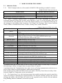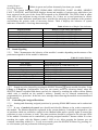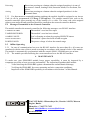
1
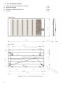
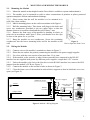
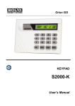
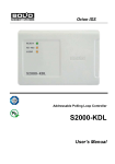
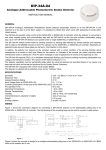
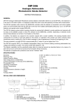
CONTROL AND INDICATOR MODULE
S2000-BKI
INSTRUCTION MANUAL
1
GENERAL TECHNICAL DATA
1.1. GENERAL
1.1.1 S2000-BKI Control and Indicator Module (hereinafter referred to as the module) is designed
to operate as a part of an ORION ISS, under a network controller, along with such devices as
Signal-10, Signal-20, Signal-20М, Signal-20P, S2000-4, S2000-KDL, etc. The network controller
can be either S2000M fire and alarm console of version 2.03+ or a PC with installed ORION Pro
software. Also the module can perform some functions under S2000 fire and alarm console
(displaying statuses of only intrusion and fire partitions).
1.1.2 The module provides light and sound indication of statuses of assigned ORION ISS
partitions as well as arming and disarming the partitions by pressing module’s buttons.
1.1.3 The module is to be mounted inside the premises and is destined for round-the-clock
operation.
1.1.4 The module must not be used in aggressive medium or dust condition, or in explosionhazardous premises.
1.2
SPECIFICATION
Light Indication
Built-in Sounder
Tamper Switch
RS-485 Communication Port
(to work as a part of Orion ISS)
Input Power
Consumed Power
Consumed Current
in alarm mode
in quiescent mode (all
indicators are off)
Pre-Operation Time
Weight
Programming
Reader Input
Ingress Protection Rating
Operating Temperatures
- 60 bicolor LEDs to display statuses of up to 60
partitions of an ORION ISS, and
- 7 single color LEDs to display alarms and troubles in
the assigned partitions as a whole, and
- A LED to display module’s status (READY), and
- A LED to display system reaction to users’ trying to
arm/disarm partitions (ACCESS)
- Yes
- Yes
- Yes
- (10.2 to– 28.4) V dc. We advise to use battery backed
power supplies of RIP series manufactured by the
Bolid Company
- 3 W max
-
200 mА max at 12 V dc
100 mА max at 24 V dc
50 mА max at 12 V dc
50 mА max at 24 V dc
2 s max
0.6 kg max
By means of UProg or UProg Free Configuration Tool
1 for a reader with Touch Memory output interface
IР20
−30 to +50°С
1
1.3
1)
2)
3)
4)
STANDARD DELIVERY
S2000-BKI Control and Indicator Module
Instruction Manual
Woodscrew and Wall Plug 6х30
Package
Front View:
Rear View:
Two holes to attach the module on the wall
Two holes to pass the cables
Figure 1. View, Overall and Mounting Dimensions
2
– 1 pcs.
– 1 pcs.
– 4 pcs.
– 1 pcs.
2
MOUNTING AND WIRING THE MODULE
2.1. Mounting the Module
2.1.1. Mount the module at that height from the floor which is suitable to operate and maintain it.
2.1.2. The module is to be mounted on walls or other constructions of premises at places protected
against atmospheric fallouts and mechanical damage.
2.1.3. Please ensure that the wall the module is to be mounted to is
solid, flat, clean, and dry.
2.1.4. Mark 4 mounting places on the wall in accordance with Figure 1.
2.1.5. Drill the mounting holes. Then insert wall plugs to the holes and
screw two woodscrews provided to the two upper holes so that the
distance between a woodscrew head and the wall is about 7 mm.
2.1.6. Remove the front cover of the module by bending it relative to
point «0» in accordance with Figure 2. Place your thumbs over the clips
as close to the point «0» as you can.
2.1.7. Hang the module on two woodscrews. Screw the remaining
woodscrews into the lower mounting holes and fix the module on the
Figure 2.
wall.
How to Open the Front Cover
2.2. Wiring the Module
2.2.1. Connect wires to the module’s terminals as shown in Figure 3.
2.2.2. Please do not confuse the polarity connecting the module to the power supply/supplies.
2.2.3. Use wires with the cross section of no more than 1.5 sq. mm.
2.2.4. If the module, or the console, or other Orion system devices connected to the RS-485
interface bus are supplied with power by different power supplies, couple their “0V” circuits.
2.2.5. Unless the module is the last or the first device in the RS-485 interface bus, remove the EOL
jumper from the module’s PCB (see Figure 3).
2.2.6. Connect the module to the external reader as shown in Figure 3.
2.2.7. Close the front cover of the module in order which is opposite to that in which the cover was
open (see Figure 2).
to the power supplies
+
620Ω EOL jumper
sounder
+
RS-485
А В +
0V
+
S2000 Console
connecting to the
Orion ISS
S2000M Console
LED GRN
0V
ТМ
tamper switch
2 holes to thread wires
iButton reader
ORION Pro
Software
Figure 3. Module’s Wiring Diagram
3
3
INSPECTING THE MODULE
3.1
To make sure your S2000-BKI module keeps proper operability, it must be inspected by a
competent specialist at least on receipt and annually.
3.2
Inspect the module at following ambient conditions:
− The relative humidity 45% through 80%;
− The ambient temperature 15°C through 35°C;
− The atmospheric pressure 630 mm Hg through 800 mm Hg.
3.3
While inspecting the module, always shut off the module’s power before connecting and
disconnecting its external circuits.
3.4
Full inspection of the module implies inspecting the module’s operability and testing module’s
indication in self-diagnostic mode.
3.5
Inspecting Operability of the Module
3.5.1 To inspect module’s operability, use an S2000M fire
and alarm console.
3.5.2 Connect the module’s RS-485 circuits and power
circuits to the relevant terminals of the console (see the
S2000M manual for detailed instructions).
3.5.3 Connect a milliammeter in series with the power
circuit of the module.
3.5.4 Apply power to the module and the console.
3.5.5 READY LED of the S2000-BKI shall switch on in
Figure 4
green within 2 s.
3.5.6 Measure the current consumed by the module. Its
value shall not exceed 200 mА.
3.5.7 Within a minute since powering on the console it shall display a message about detecting a
device with the network address assigned to the S2000-BKI (factory value of the module address
is 127). Figure 4 shows the display of the S2000M console with the relevant message.
3.5.8 If several messages accumulated by the module have been received by the console, you
can browse them by the arrow buttons «◄» and «►» on the S2000M.
3.6
Testing the Module in the Self-Diagnostic Mode
3.6.1 Initiate the self-diagnostic mode, pressing the SILENCE button
three times for a short
time and once for a long time. “Short time” means holding the button pressed for 0.1 s to 0.5 s
while “long time” means holding the button pressed for at least 1.5 s. Pauses between pressings
should be 0.2 to 1 s.
3.6.2 If the module operates correctly, its LEDs turns on in the following order:
a) Columns of LEDs «1» to «60» turn on one-by-one in green, then in red, then the following indicators
turns on simultaneously, with FIRE, PREALARM, INTRUSION, PANIC ALARM, ARMING
FAULT indicators being lighting in red, OFFLINE and TROUBLE indicator being lighting in
yellow, and READY indicator being lighting in green;
b) Strings of LEDs «1» to «60» turn on one-by-one in green, then in red, then the indicators FIRE,
PREALARM, INTRUSION, PANIC ALARM, ARMING FAULT turn on one-by-one in red, then
indicators OFFLINE and TROUBLE turn one-by-one in yellow, then READY indicator turns on in
green;
c) LEDs «1» to «60» turn on in yellow, and simultaneously the indicators FIRE, PREALARM,
INTRUSION, PANIC ALARM, ARMING FAULT turn on in red, indicators OFFLINE and
TROUBLE turn on in yellow, indicator READY turn on in green;
4
d) LEDs «1» to «60» turn on in green, and simultaneously indicators FIRE, PREALARM,
ARMING FAULT turn on in red while TROUBLE indicator turns on in yellow;
e) The procedure c) is repeated, then indicators «1» - «60» turn off while single-color indicators
keep flashing;
f) Each LED from «1» to «60» turns on when its adjacent button is pressed.
or
3.6.3 The module exits the self-diagnostic mode after pressing the SILENCE button
automatically after 30 s since last pressing on a module’s button.
4 PROGRAMMING THE MODULE
4.1 To be adjusted for the specific application, the module supports programming its
configuration parameters stored into its non-volatile memory. The parameters can be programmed
by UProg or UProgFree Configuration Tool installed on a PC which the module is connected to
via one of the interface converters PI-GR, S2000-PI, S2000-USB, USB-RS485, or console
S2000М or S2000 (of version 1.20+). The last versions of UProg and UProgFree as well as
additional information about the module are available at the web-address of www.bolid.com.
Table 1 shows the configuration parameters of the module.
Table 1. Module’s Configuration Parameters
Parameter
Description
Value Range
The number of the partition (in the
network controller’s database)
0 – 9999
Partition Number
assigned to this LED
Intrusion, Intrusion 2,
Defines the modes of indicator’s
Fire,
lighting depending on the types of
LED Type
alarm loops included to the
Auxiliary, Auxiliary 2,
partition
Engineering
Arming, Disarming,
Defines the rights to control
Button Action
Arming/Disarming,
partitions
Unused
0: no sound (mute),
Alarm Sounding The time period, after elapsing of
1 s to 244 s: sounding,
Time
which module’s sounder is shut off
255: sounds until reset
The code for free mode of
Access Code
arming/disarming by pressing
0000 – 9999
module’s buttons (see 5.3.3)
This option provides monitoring
Two Power
power troubles on both of the
Inputs
On/Off
power supplies connected to the
Monitoring
module
The admissible delay for the device’s
3 milliseconds to500
Response Pause responding to a network controller
milliseconds
request
The address of the module within
Network Address
1 – 127
the RS-485 interface bus
Factory Value
1 – 60
Intrusion
Unused
255
Empty
Off
3 ms
127
5
5
5.1
MODULE OPERATING MODES
Indication Modes
5.1.1
Table 2 displays behavior of the module’s READY LED depending on module’s statuses.
Table 2. READY Indicator Behavior
Module Status
Norm
No connection over the RS-485 interface bus
Programming (updating the firmware)
READY Indicator Behavior
Lit steady
Flashes twice per second
Flashes four times per second
5.1.2 Table 3 displays lighting modes of indicators «1» to «60» depending on statuses of
associated partitions taking into account given indicator’s types. If several messages have been
received from the same partition, the event of the highest priority is to be indicated. Following are
the messages in descending order of priority: Fire Alarm, Fire Prealarm, Panic Alarm, Intrusion
Alarm, Offline (Communication Loss), Trouble, Arming Fault, Armed, Disarmed.
Table 3. Behavior of LEDs «1» to «60»
Partition Status
Behavior of LEDs «1» to «60»
Lit steady in green (for LEDs of the Fire type) or in red (for LEDs of other
Armed
types)
Arming
Blinks in green four times per second
Off for LEDs of the Intrusion 2 and Engineering types,
Disarmed
Blinks in yellow (0.25 s on / 1.75 s off) for LEDs of the Fire type,
Lit steady in green for LEDs of other types
Intrusion Alarm
Blinks in red (0.5 s on / 0.5 s off)
Entrance Alarm
Blinks in red (0.5 s on / 0.5 s off)
Panic Alarm
Blinks in red (0.5 s on / 0.5 s off)
Arming Failed
Blinks in green (0.5 s on / 0.5 s off)
Fire Alarm
Blinks in red (0.25 s on / 0.25 s off)
Fire Pre-Alarm
Blinks in red (0.25 s on / 0.75 s off)
Trouble
Blinks in yellow (0.25 s on / 0.75 s off)
Communication Loss
Blinks in yellow (0.5 s on / 0.5 s off)
Blinks in yellow (0.25 s on / 1.75 s off) for LEDs of the Auxiliary type,
Auxiliary Zone Alarm
Lit steady in yellow for the LEDs of the Auxiliary 2 type
Off for LEDs of the Auxiliary type,
Auxiliary Zone Restored
Lit steady in green for the LEDs of the Auxiliary 2 type
High Temperature
Blinks in red (0.25 s on / 0.25 s off) for LEDs of the Engineering type
Low Temperature
Blinks in red (0.5 s on / 0.5 s off) for LEDs of the Engineering type
Norm Temperature
Lit steady in green for LEDs of the Engineering type
Fire Equipment Restored Lit steady in green for LEDs of Fire type
A partition enters the Trouble status in case of short or open failure of alarm loops, or detector’s
disconnecting or failure, or tamper alarm, or power failure or shutoff.
A partition enters the Communication Loss status in case of losing communication with devices or
power failure within an assigned multiplex addressable polling loop.
If the module operates under an S2000 console, the statuses Auxiliary Zone Alarm, Auxiliary Zone
Restored, High/Low Temperature can be not indicated.
5.1.3 If a button from «1» to «60» has been pressed, the module transfers the network controller a
request for arming or disarming the assigned partition. The network controller analyses the received
message and makes a decision about the access to the requested action, with the relevant indicator
being blinking until the command is executed or rejected:
6
Arming Request
Disarming Request
Blinks in green and yellow alternately four times per second
5.1.4 The system indicators FIRE, PREALARM, INTRUSION, PANIC ALARM, ARMING
FAULT, OFFLINE, and TROUBLE displays alarms and troubles of various types which have just
been occurred in the part of the Orion ISS assigned to the S2000-BKI. This LEDs flash in phase
with LED of the partitions having relevant statuses. So, if there are several partitions in various
statuses, the status indicators mentioned above provide fast analyzing the situation at the premises
and defining the priority order of necessary actions. Table 4 displays the behavior of system
indicators on module’s receiving alarm messages.
Table 4. Behavior of Single-Color Indicators
Partition Status
Fire Alarm
Fire Pre-alarm
Intrusion Alarm
Panic Alarm
Arming Failed
Communication Loss
Trouble
5.2
Behavior of the Relevant Indicator
Red: 0.25 s on / 0.25 s off
Red: 0.25 s on / 0.75 s off
Red: 0.5 s on / 0.5 s off
Red: 0.5 s on / 0.5 s off
Red: 0.5 s on / 0.5 s off
Yellow: 0.5 s on / 0.5 s off
Yellow: 0.25 s on / 1.75 s off
Sound Signaling
5.2.1 Table 5 demonstrates the behavior of the module’s sounder depending on the statuses of the
partitions assigned to all the module’s indicators.
Table 5. Sounder Behavior
Partition Status
Fire Alarm
Fire Pre-alarm
Intrusion Alarm
Panic Alarm
Trouble
Request for Arming/Disarming by iButton
Access Denied for the iButton
Access Granted for the iButton
Communication Loss
Other
Sounder Behavior
0.75 s on / 0.25 s off
Beeps twice for 0.25 s each time every 2 s
0.25 s on / 0.25 s off
0.25 s on / 0.25 s off
0.25 s on / 1.75 s off
Beeps for 0.25 s
Beeps for a second
Beeps for a quarter of a second
Beeps four times per second
Off
5.2.2 Sounds are to be silenced by pressing the SILENCE button
on the module faceplate. Using
UProg or UProgFree Configuration Tool you can restrict access to silencing alarms, when the
SILENCE button is disabled and alarms can only be silenced by touching the reader with an iButton
which code is enrolled on the module’s memory. Sounds can be silenced automatically (if
programmed) in a given time. In the last case a message about silencing the module are not transferred
to the console.
5.3 Controlling the Assigned Partitions
5.3.1 Arming and disarming assigned partitions by pressing S2000-BKI buttons can be authorized
or free.
5.3.2 In case of authorized control user should touch her/his iButton to the reader connected to
the module. The iButton should be registered in the system database. It should be assigned to a list
of partitions which are enabled to control for the iButton holder and to specific rights to control the
partitions (to arm, to disarm, or both). The same partitions should be assigned to the relevant LEDs
of the module. Partitions can be controlled by pressing assigned module’s buttons within 20 s since
touching the reader with the iButton (reader’s LED is on). After pressing the buttons you can
continue controlling within 10 s. To exit access mode, press the SILENCE button. By pressing «1»
to «60» buttons you can perform the following actions:
7
Disarming
Short-time pressing on a button when the assigned partition is in one of
the statuses: Armed, Arming Failed, Intrusion Alarm, Fire Prealarm, Fire
Alarm
Arming
Short-time pressing on a button when the assigned partition is in the
Disarmed status
5.3.3 For free access to arming/disarming partitions the module should be assigned to an Access
Code (it can be programmed by UProg or UProgFree). The module transfers this code to the
network controller upon pressing any of the buttons «1» to «60». The same code with assigned
rights to arm and/or disarm partitions should be enrolled on the network controller database.
5.4 Messages Transmitted to the Network Controller
The module transfers the network controller the following messages over RS-485 interface:
The module’s case has been open
The module’s case has been closed
TAMPER RESTORED
User’s silencing an alarm by pressing SILENCE button
ALARM CANCEL
The module’s power has been off and on again
DEVICE RESTART
The power voltage is below the normal range
POWER FAILED
TAMPER ALARM
5.5 Offline Operating
5.5.1 In case of communication loss over the RS-485 interface for more than 60 s, all events are
transferred with the time of their actual occurring in accordance with internal clocks of the module.
The module is automatically synchronized with the console S2000 / S2000M once per an hour.
5.5.2 The module provides buffering the events transferred over the RS-485 interface.
6
MAINTENANCE
To make sure your S2000-BKI module keeps proper operability, it must be inspected by a
competent specialist at least on receipt and annually. The inspection algorithm shall include:
–
Visual checking the S2000-BKI against contaminations and mechanical damage;
–
Verifying the S2000-BKI for secure mounting and wire connection conditions;
–
Inspection of the S2000-BKI operability in accordance with Section 3 of this Manual.
ZAO NVP Bolid, 4 Pionerskaya Str., Korolev 141070, Moscow
Region, Russia
Phone/fax: +7 495 775-7155
Email: [email protected], [email protected]
www.bolid.com
8