1
Restrained Re-Engineering
of an IP Header Compression Simulator
NIKLAS VARGENSTEN
Master’s Degree Project
Stockholm, Sweden 2004
TRITA-NA-E04157
Numerisk analys och datalogi
KTH
100 44 Stockholm
Department of Numerical Analysis
and Computer Science
Royal Institute of Technology
SE-100 44 Stockholm, Sweden
Restrained Re-Engineering
of an IP Header Compression Simulator
NIKLAS VARGENSTEN
TRITA-NA-E04157
Master’s Thesis in Computer Science (20 credits)
at the School of Computer Science and Engineering,
Royal Institute of Technology year 2004
Supervisor at Nada was Serafim Dahl
Examiner was Stefan Arnborg
Abstract
This project is a software re-engineering project. What we have is a functional system
named HC-Sim that suffers from lack of user interaction and data presentation capabilities.
Using software engineering techniques such as system analysis and design, a detailed and
comprehensible model for an improved system is created and then implemented. The new
system makes use of object-oriented techniques, as opposed to the original system, which is
purely function-based. Re-engineering of the existing system is not straightforward, due to
the fact that the existing system should be modified as little as possible. We must therefore
take a restrained approach, aiming at expanding the system rather than rebuilding it.
In many projects of this type, the design of the original system is used as a basis for the
design of the new system, but in this project we do things a bit differently. During the
analysis and design process of this re-engineering project, we also study the design and the
implementation of the original system and try to figure out how it might be improved in the
light of object-oriented thinking. At the end of the project, with the aid of this knowledge, a
more detailed study and a proposition for how HC-Sim could be re-designed to better meet
with future needs is produced.
Sammanfattning
Detta projektarbete går ut på att förbättra ett befintligt dataprogram vid namn HC-Sim. Det
existerande mjukvarusystemet är fullt fungerande, men har begränsade interaktionsmöjligheter och är bristfälligt vad gäller presentation av data för slutanvändaren. Med hjälp
av systemanalys och mjukvarudesign skapas därför en detaljerad och tydlig modell för ett
nytt system, varefter denna implementeras. I det nya programmet används objektorienterade
lösningar, till skillnad från det gamla system som är funktionsbaserat. Att göra om systemet
är ingen enkel uppgift, eftersom det är önskvärt att så få ändringar som möjligt görs i
ursprungsprogrammet. Vi måste därför ha ett återhållsamt tillvägagångssätt, och eftersträva
att utvidga systemet istället för att göra om det, för att uppnå våra mål.
Det är logiskt att man i projekt av den här sorten bör utgå från det ursprungliga systemets
design när det nya systemet skapas, men i detta projekt nyttjas ett lite annorlunda
tillvägagångssätt. Under det att det nya systemet skapas studerar vi hur det befintliga
systemet har designats och implementeras, och betänker hur detta skulle kunna göras
annorlunda och bättre utifrån en objektorienterad synvinkel. I slutet av projektet används
denna kunskap till att utföra en mer detaljerad studie av hur en eventuell omskrivning av
HC-Sim skulle kunna göras, så att programmet bättre ska kunna leva upp till nya krav i
framtiden.
Table of contents
Background
1
List of acronyms used .....................................................................................................................1
Project initiator................................................................................................................................1
Effnet products................................................................................................................................1
IP Header compression ...................................................................................................................2
HC-Sim - the mandatory system .....................................................................................................2
Purpose of the project......................................................................................................................3
An overview of the project
4
The process .....................................................................................................................................4
General guidelines...........................................................................................................................5
Requirements elicitation
7
Requirements ..................................................................................................................................7
Actors..............................................................................................................................................8
Scenarios .........................................................................................................................................9
Use cases.......................................................................................................................................10
The analysis process
13
Strategy .........................................................................................................................................13
Usability........................................................................................................................................14
Imposed requirements ...................................................................................................................15
Analyzing the feedback.................................................................................................................16
Program control.............................................................................................................................19
System design
20
Meeting with the requirements......................................................................................................20
GUI as a front-end or as integrated software ................................................................................21
Interaction between HC-Sim and HC-Sim GUI............................................................................23
Information management ..............................................................................................................30
Graphical design ...........................................................................................................................39
Implementation
45
Resources ......................................................................................................................................45
Threads and synchronization.........................................................................................................47
Editing the HC-Sim code ..............................................................................................................49
Data acquisition and presentation .................................................................................................54
Striving towards usability .............................................................................................................59
Managing the project ....................................................................................................................62
Review of HC-Sim GUI
63
Successes.......................................................................................................................................63
Drawbacks.....................................................................................................................................63
Uncertainties .................................................................................................................................64
Suggestions for future functionality..............................................................................................65
Plan for re-engineering
67
Purpose..........................................................................................................................................67
Requirements ................................................................................................................................68
Analysis.........................................................................................................................................69
Re-design ......................................................................................................................................74
Review of the re-engineering ........................................................................................................83
Conclusions of the project
84
References
85
List of specific references .............................................................................................................85
List of sources ...............................................................................................................................85
List of appendices .........................................................................................................................86
Index of figures
Figure 1.
Figure 2.
Figure 3.
Figure 4.
Figure 5.
Figure 6.
Figure 7.
Figure 8.
Figure 9.
Figure 10.
Figure 11.
Figure 12.
Figure 13.
Figure 14.
Figure 15.
Figure 16.
Figure 17.
Figure 18.
Figure 19.
Figure 20.
Figure 21.
Figure 22.
Figure 23.
Figure 24.
Figure 25.
Figure 26.
Figure 27.
Figure 28.
Figure 29.
Figure 30.
Figure 31.
Figure 32.
Figure 33.
Figure 34.
Figure 35.
Figure 36.
Figure 37.
Figure 38.
Figure 39.
Figure 40.
Figure 41.
Figure 42.
Figure 43.
Figure 44.
Figure 45.
Figure 46.
Figure 47.
Figure 48.
Figure 49.
Figure 50.
Relationship between IP header compression and the conceptual layers of TCP/IP...........2
The modular architecture of HC-Sim. .................................................................................3
How a header compression library is integrated with HC-Sim. ..........................................3
Examples of the use of UML class diagrams. .....................................................................6
Intersecting lines are resolved by using connection points. ................................................6
Actors operating upon the system from an external point of view......................................8
Actors operating upon the system from an internal point of view. .....................................8
Header compression simulation use case diagram. ...........................................................12
The design strategy of HC-Sim GUI.................................................................................13
HC-Sim with no GUI runs in a single- threaded process. .................................................22
The HC-Sim GUI process creates another process to execute HC-Sim. ...........................22
HC-Sim GUI thread and HC-Sim thread running in the same process. ............................22
The relationship and interaction between the HC-Sim side and the HC-Sim GUI side. ...23
Implementation of a bridge between the two sides of HC-Sim GUI.................................25
State chart diagram for the execution of the HC-Sim thread.............................................26
State chart diagram showing callbacks made by the HC-Sim thread in a simulation. ......26
State chart diagram for the execution of the HC-Sim GUI thread.....................................27
Simulation controls related to the HC-Sim GUI thread. ...................................................28
State chart diagram for the simulation status of HC-Sim GUI..........................................28
Sequence diagram for changing the status of a simulation................................................29
Data structures for statistics wrapped in class HCSimStatistics........................................31
Upon a callback, a HCSimStatistics object is stored in a HCSimStatisticsQueue. ...........33
Difference in statistics between two instances of class HCSimStatistics. .........................34
The relationship between HC-Sim statistics, plot data and graphs. ..................................35
HCSimStatistics are transformed into plot data by an HCSimPlotdataManager...............36
The class structure of graphs in HC-Sim GUI...................................................................38
A very simple front end.....................................................................................................39
An extended front end for standalone mode only..............................................................39
Configuration constraints in a front end extended for two-machine mode. ......................41
A simple graph containing a plot of compression ratio against packets............................42
A graph with two plots of IP datagram header length against time...................................42
Statistics presented a plain numbers in the GUI................................................................43
Simulation status shown with traffic light icons (green, yellow, red). ..............................43
Simulation progress displayed numerically and graphically in a progress bar..................43
A simple error message for an invalid test case configuration..........................................44
A thread interaction handler is used to synchronize GUI updates.....................................48
HC-Sim traces can be controlled in the preferences of HC-Sim GUI. ..............................51
HC-Sim invokes functions of the callback interface through macro functions. ................52
Example of how a value can be assigned to an event callback mask. ...............................54
Which events that result in callbacks is set in the preferences of HC-Sim GUI. ..............56
A compression ratio meter in HC-Sim GUI, which is updated periodically. ....................57
A label which is updated via an HCSimStatisticsFunctionDataTarget. ........58
Screen dump showing how a user can hide graphs and plots by checking boxes. ............59
Relationship between uniform commands and resource representations. .........................61
Flow of callbacks in a distributed version of HC-Sim GUI. .............................................66
The block structure of HC-Sim. ........................................................................................70
Representing compression scheme specific component types with inheritance................76
An abstract factory encapsulates the compression scheme used by HC-Sim....................76
The structural relationship between the simulator components of HC-Sim. .....................78
Running queued sequential simulations in HC-Sim..........................................................80
Index of tables
Table 1.
Table 2.
Table 3.
Table 4.
Table 5.
Table 6.
Table 7.
Table 8.
Table 9.
Table 10.
Table 11.
Effnet header compression products and their areas of application. ...................................1
Simulation controls in HC-Sim with and without a GUI. .................................................19
Function declarations available in the HC-Sim callback interface....................................24
Statistics available at the compressor for each compression scheme. ...............................30
Statistics available at the decompressor for each compression scheme. ...........................30
The structure of the HC-Sim callback event code.............................................................32
Example of plot data for a Compression ratio – Time graph. ...........................................35
How the plot data values in the example of Figure 25 are obtained..................................37
Structural locations of callbacks for general event types in HC-Sim. ...............................52
Structural locations of callbacks for compression scheme specific event types................53
The main components of HC-Sim and their purposes.......................................................70
Background
This introduction is required in order to understand the nature of this project. First, a list
of acronyms is provided, which helps the reader to keep track of some of the more
common abbreviations used throughout the entire document. This section then teaches the
fundamentals of IP header compression, introduces the company that initiated this project,
along with some of their products, and then finally explains the project itself and its
purpose.
List of acronyms used
2.5G/3G
CRTP
dc
HC-Sim
hc
IETF
IP
IPHC
RFC
ROHC
RTP
TCP
UDP
Third generation of mobile communication networks
Compressed Real-time Transport Protocol
Header Decompressor/Decompression
Header Compression Simulator
Header Compressor/Compression
Internet Engineering Task Force
Internet Protocol
Internet Protocol Header Compression
Request For Comments
Robust Header Compression
Real-time Transport Protocol
Transmission control protocol
User Datagram Protocol
Project initiator
The company that initiated the project is called Effnet AB1. Their main area of business is
IP header compression product development. The company is a part of Effnet Holding
AB, which also includes Factum Electronics AB.
Effnet products
Based on different IETF standards (RFCs) for IP header compression, Effnet AB has
developed three header compression libraries: IPHC[7], CRTP[8] and ROHC[9], each
with different traits and suitable areas of application (see Table 1). These three
implementations are marketed as separate products to customers who wish to improve
their network link efficiency, particularly in the areas of mobile applications and
telephony. Customers are mainly manufacturers of 2.5G and 3G handset and
infrastructure equipment.
Table 1.
1
Effnet header compression products and their areas of application.
Product
IETF
Suitable areas of application
IPHC
RFC 2507
CRTP
RFC 2508
ROHC
RFC 3095
Low and medium speed links.
Real-time applications with audio/video over low and medium
speed links.
IP over cellular radio links.
Effnet stands for efficient networking
1
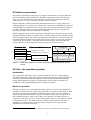
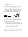
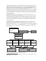
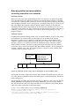
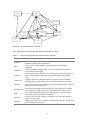
IP Header compression
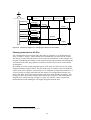
The purpose of IP header compression is to improve link efficiency, increase speed and
provide reliability in IP based networks. IP header compression is part of the network
stack in the conceptual model of the TCP/IP layers [2](i), the relationship to which is
shown in Figure 1. Loosely described, the basic idea is as follows:
Most IP datagrams contain much header information that never or rarely changes. By
sending datagrams in a specific type of frame, these data can be established as a context at
the beginning of a communication session. In the course of packet transmission between
two links, IP header data need only be transmitted when that context is changed, thus
reducing the number of bytes transmitted over the link.
Each IP datagram that is passed to and from the Internet layer to the network layer will go
through the header compressor, which creates a specific compressed frame header instead
of the original IP header. The compressed datagram is then placed in a network frame and
transmitted. When the frame arrives at the network layer at the receiving side, the header
compression specific frame is extracted from the network frame at the decompressor,
converted back to a full IP datagram and then passed on to the Internet layer.
Conceptual layer
Objects passed between layers
Application
Transport
Internet
Network
Hardware
Figure 1.
Messages or streams
IP datagrams
Compressor
Decompressor
Transport protocol packets
Compression protocol frames
IP Datagrams
Network-specific frames
Network-specific frames
Relationship between IP header compression and the conceptual layers of
TCP/IP.
HC-Sim - the mandatory system
Introduction
The system upon which this project is based is called HC-Sim. It is a multi-purpose
simulation environment for the three header compression products marketed by Effnet. It
is used by Effnet Research & Development for internal and external interoperability
testing, Effnet Marketing & Sales for demonstration and by Effnet's customers for
verification of the integrated Effnet header compression product.
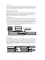
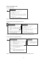
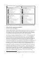
Modes of operation
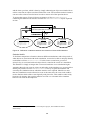
HC-Sim can operate in several simulation modes, either in a network environment or as
standalone without a network. When using a network, two instances of HC-Sim are used.
The data may either be encapsulated in IP/UDP packets or placed directly in Ethernet
frames, and then sent between the compressor and the decompressor (see Figure 2). As
both simulator instances contain each of these, one simulator runs either mainly as a
compressor, referred to as Charles mode, and the other mainly as a decompressor, which
is called Diana mode 2. The stream of data can either be generated from a test file or
supplied by an external source. If using the latter, the packets are in general also
forwarded to an external destination.
2
The HC-Sim user manual also calls these modes compressor- and decompressor-mostly part.
2
If not using a network, only one instance of HC-Sim, acting both as Charles and Diana, is
used. A test file defines the data flow and traffic conditions, or a simulation can be re-run,
referred to as playback, from a time-stamped log file produced by a previous simulation.
Each compressor-decompressor pair exchanges information via a channel, connecting
Charles and Diana. For details regarding HC-Sim operation, see the Effnet HC-Sim user
manual [10].
Charles side
(compressor mostly)
Packet source
or generator
Compressor
Decompressor
Figure 2.
Diana side
(decompressor mostly)
Decompressor
Channel
or network
Packet sink
or destination
Compressor
The modular architecture of HC-Sim.
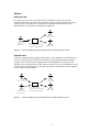
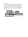
Technical details
In order to enable testing of the header compression products in different environments,
HC-Sim is a multi-platform program. Just like the header compression libraries, it is
implemented in ANSI-C.
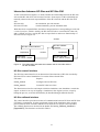
The header compression product to test does not need to be a part of the network layer, as
the HC-Sim executable is linked with the header compression library, this way enabling
header compression to take place in the application layer. For each header compression
library there is a corresponding set of glue code files to fill the gap between the HC-Sim
base code and the library used for header compression (see Figure 3).
For full details, see the Effnet HC-Sim Architecture overview description [11].
IP header compressor
IP header decompressor
Figure 3.
Glue
code
HC-Sim base
code
How a header compression library is integrated with HC-Sim.
Purpose of the project
Effnet AB have offered me the task of designing and implementing a graphical user
interface for HC-Sim. The new program is to be used as a complement to the original
system, but be more adapted for live presentations and customer demonstrations of Effnet
IP header compression products.
During the course of this project, HC-Sim is being developed alongside with the new
program. Effnet have no intention of abandoning the original system, and it is therefore of
great importance that changes to the existing program that are made for the sake of this
project do not interfere with that development process. The term restrained reengineering used in the title of this document refers to this fact, which will be quite
obvious as the development of the new system progresses.
For more details about the project, please see the Project specification [Appendix A].
3
An overview of the project
The process
The steps involved in the design process are more or less done by the book – the book
being Object-oriented software engineering [1]. Since that book mostly focuses on pure
object-oriented development, however, some of the tasks described therein in are either
performed a bit differently or skipped altogether. By working by the book it is our aim to
cover most of the relevant tasks involved in designing the system. As we are also well
aware of the differences between this project and your average school-book design
challenge, it will also be necessary to come up with our own solutions and ways of
modeling in order to lay the focus where it is best needed for this project.
Requirements elicitation
Defining the basic requirements of the system from a user’s point of view is the very
foundation of the project. By creating scenarios and producing use cases we wish to get a
clear view of who will be using the system, how, and for what purpose.
Analysis
The results of the requirements elicitation are evaluated and weighed against the
mandatory system. The analysis will be used as a guide in the system design section, and
will also be of great value when analyzing re-engineering issues at the end of the project
(see Plan for re-engineering).
System design
This is where the basic elements of the system are created. The design does not cover the
whole system, but rather pieces of a puzzle that is put together in the implementation
process. This step also leans a bit into the implementation part, as some interfaces and
rules of integration are defined here.
Implementation
In this phase we will motivate and explain the implementation choices that are actually
used to create HC-Sim GUI. The implementation does not aim at producing a final
product, but rather at creating a functional demo, which can be used as a basis for further
development by Effnet AB.
Review
After implementing the system, we analyze any occurring problems with the design and
implementation, and speculate on what could have been done differently or better.
Suggestions for future additions and improvements are also made here.
Plan for re-engineering
At the end of the project, after which a functional demo has been produced and
documented, we are free to speculate on how the existing system could be re-designed
more thoroughly. We expand our analysis in order to examine how the design and
implementation of HC-Sim could be made more flexible, powerful and developerfriendly. This section is meant to be used as an inspiration to Effnet for future
consideration and implementation. I see it as a side-product of the project, one that
represents what I would have done if I had been given the time and the opportunity.
4
General guidelines
Choice of technique
The complete process of software design from idea to product is not covered by this
project. We will instead only focus on the most important concepts, the highlights, of the
design process. In general, most techniques for these activities are labeled as either being
object-oriented or not. Figuring out how can we make these techniques apply to this
project is a bit of a challenge, since we already have a mandatory system which is
implemented in a function based language while we3 wish to implement the new part of
the system in the light of object-oriented thinking.
Use of the names HC-Sim and HC-Sim GUI
We will often make a distinction between HC-Sim and HC-Sim GUI in the design
process, the referred meanings of which require a clarification. When talking about
HC-Sim and HC-Sim GUI we mean that HC-Sim GUI is the newly designed part that is
integrated with HC-Sim to form a complete program. HC-Sim GUI is also the name of the
entire project, that is HC-Sim extended with a graphical user interface. To clarify this
difference when the context does not, we will refer to the HC-Sim side and the HC-Sim
GUI side (or simply GUI side) when we are talking about the two as separate parts of the
entire program.
Code excerpts and examples
General conventions
All code examples used in this document are either written in C/C++ or in pseudo-code
similar to these languages. The code is highlighted with a monospace font face. Parts of
the code that are omitted in the examples are represented by three dashes (---).
code example)
void startSimulation(int argc, char **argv) {
--- // verify parameters
sim_init();
sim_run();
}
Types used
C/C++ types
Standardized types such as void, char, int and bool are used in this document.
HC-Sim specific types
Effnet uses the same definitions of types in all their header compression products and in
HC-Sim, and these types will be used in HC-Sim GUI as well, in particular in code that is
closely related to code of the original system. The types used in this document are:
i32_t
u32_t
i8_t
u8_t
32 bit signed integer
32 bit unsigned integer
8 bit signed integer
8 bit unsigned integer
3
The project specification provided by Effnet AB makes no recommendation on what technique to
use. An object-oriented solution is my choice, wherefore we could be interpreted as me, the author,
and maybe also the reader, should he be inclined to agree with my point of view.
5
Other specific types
FOX [15], the graphical library used for the GUI implementation (see Choice of graphics
library, page 45), has many defined types and classes, all of which are designed to work
the same on different platforms. Each of these has a type name that begins with the letters
FX, for instance FXint and FXString.
Regarding the use of UML
Throughout this document we will use several UML [13] diagrams to explain designs,
events and relationships between components. While only standard diagrams such as class
diagrams and state chart diagrams are used, some of them have minor modifications and
additions in order to make them more suitable for our purposes.
Class diagrams
The class boxes of UML class diagrams have been given the ability to represent dummy
classes, by which we mean a representation of some class (or a set of classes) which will
not be explained in detail due to lack of relevance or to risk of only adding unnecessary
complexity to a diagram. Class diagrams are sometimes also used to explain simple chains
of events, by simply using dashed arrows and text to explain the course of action directly
in a class diagram. UML class constraints and operators such as for instance
<<instanceof>> and <<abstract>> are also employed at will. Some examples of the use of
class diagram boxes are provided in Figure 4.
ClassA
ClassB
Class …
<<abstract>>
RealAbstractClass
mySingleInstance
myFunction()
<<instanceof>>
DummyConcreteClass
myFunction()
Figure 4.
<<singleton>>
RealConcreteClass
myFunction()
SingletonObjectUser
doStuffWithSingleton()
Examples of the use of UML class diagrams.
Line notations
It is not uncommon when viewing class and object diagrams that one experiences the
picture as impossible to interpret due to a great number of lines and arrows crossing each
other. To make sketches less compact and tangled, line intersections and situations where
several individual lines would normally be used are resolved by replacing several lines
with one, using forks and highlighting of the points of connection (Figure 5). This idea is
borrowed from the field of electricity, where it is often used to handle crossed wires in
circuit diagrams.
AssociatedClassα
SubClass1
AssociatedClassβ
SubClass2
AssociatedClassγ
SubClass3
BaseClassA
BaseClassB
Figure 5.
Intersecting lines are resolved by using connection points.
6
Requirements elicitation
This section states the intended purpose of HC-Sim GUI – the new version of the header
compression simulator known as HC-Sim. Besides defining the functional, non-functional
and pseudo requirements of the new system, we also define the actors of the system and
explain how the program is intended to be used under different circumstances, by whom,
and for what purpose.
Requirements
Non-functional requirements
HC-Sim GUI is an IP header compression simulation environment, which covers the same
area of application as HC-Sim. The graphical data presentation of the program also makes
it suitable for demonstrations of the products for potential customers. The technical details
of the simulator and the complex nature of header compression, however, suggest that
simulation setup still is made by a professional, as most of both the input and output data
require an explanation in order to be interpreted by a layman.
Functional requirements
HC-Sim GUI extends the IP-header compression simulator HC-Sim with a graphical user
interface, allowing any number of simulations to be run sequentially in a program session.
The events and output of a simulation is presented to the user through graphical indicators
such as progress bars and graphs, or numerically when required. The type and amount of
data displayed to the user during the simulation can be controlled through settings,
enabling the user to view details of a specific type of simulation data, or to see an
overview of simulation events. The displays are updated continuously during the
simulation.
The controls of the user interface are sparse, compact and easy to use for a user with basic
experience of graphical user interfaces, as only standard components and widgets such as
check buttons, radio buttons and menus are used. The graphical user interface makes it
easier to set up a simulation than with the original command-based user interface, mostly
because invalid configurations are suppressed by the graphical interface. The program
hints the user on how to input valid data, and also supports the ability to save
configurations between program sessions.
Pseudo requirements
The program should be easily further expandable by Effnet, as well as easy to setup,
compile and build. This requires the system to be well documented with an inclination to
facilitate further development, refactoring and redesign. The program itself and the
graphical library used must be portable to all platforms supported by HC-Sim, and in
addition be so low demanding in resources that they do not pose a severe impediment to
the execution of a simulation. The GUI should also not be too tightly integrated with HCSim, as the original version must be runnable on platforms and environments in which
graphical components cannot be used due to limited resources.
7
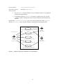
Actors
External view
In a general sense, a user or operator makes a simulation setup to test a header
compression product, optionally with a network acting as data generator and receiver
(Figure 6). The spectators may for instance be potential customers during a live
demonstration, or developers evaluating the simulation.
Spectator
User/
operator
Figure 6.
HC-Sim GUI
integrated with
IPHC/CRTP/ROHC
Network
Actors operating upon the system from an external point of view.
Internal view
From the viewpoint of the program itself (Figure 7), the controller of a simulation is a
scenario set up by the user. The scenario consists of an optional simulator input file
(simply called a test file) and configurations made through the user interface. The
simulator may read data from and write data to log files, receive and send data over the
network and present simulation events and other types of information on the computer
screen, using text and graphics.
Screen
Log files
Simulator
scenario
Figure 7.
HC-Sim GUI
integrated with
IPHC/CRTP/ROHC
Network
Actors operating upon the system from an internal point of view.
8
Scenarios
To exemplify how we intend for the system to be used in various situations, we identify
some probable scenarios. These scenarios aim at helping us to better understand the
application domain and to see how the different actors relate to the system, in particular in
terms of the actions each actor performs and the information exchanged between the actor
and the system.
Scenario name:
computerConvention
Participating actors:
roger, sean:
Operator
george, pierce: Spectator
windowsComputer,
linuxComputer,
laptopBridge:
Network
Flow of events:
1. Roger and Sean have just arrived at the 3G computer convention in Cannes.
Roger sets up a Windows 2000 and a Red Hat 9 computer serially connected via
a laptop acting as a network bridge, while Sean places a large monitor connected
to the Red Hat machine on a pedestal, enabling spectators to view the simulation.
2. Roger sets up HC-Sim GUI on the two computers, configured for a live
demonstration of ROHC efficiency in a network with non-trivial packet loss. The
Windows machine is set as compressor side and the Red Hat machine as the
decompressor side. Sean starts up a packet sniffing program on the laptop, which
shows the traffic through the network bridge.
3. George, a sales representative for IBM mobile communications, comes by and
wonders what this is. Sean gives him a crash course in header compression
technology while Roger starts the simulation, but nothing happens. Roger sees
that the sender side is configured to receive packets from an external source,
which is wrong since there is none. He stops the simulation, re-configures HCSim GUI on the sender side and re-runs the simulation. George looks at the
screen and sees a compression ratio graph being drawn 4. Pierce, who is an
experienced network technician, comes by and asks what happens if the traffic
conditions become poor. Roger makes a slight adjustment in the simulation test
file on the Windows computer and restarts the simulation.
4. Pierce looks at the laptop and sees that the number of packets dropped increases.
Pierce then looks at the large monitor and sees that the compression ratio
decreases slightly, but that the packet rate remains stable. George cannot see what
just happened, so Sean pauses the simulation, zooms in the packet graph in
HC-Sim GUI at the decompressor side and points out where the packet loss
occurred and where ROHC recovered from the loss of information.
4
Throughout the HC-Sim GUI project, the term compression ratio was incorrectly referred to as
compression rate. As the latter term was used in the source code, developers of HC-Sim GUI are
encouraged to update the code in favor of the word ratio.
9
Scenario name:
CRTPtesting
Participating actors:
luke:
User,Spectator
BSDWorkStation: Network
Flow of events:
1. Luke has been appointed the task of comparing the compression ratio and
packet transmission count when running a RTP flow through the simulator as
IPv4 and IPv6 packets. A co-developer has pointed out that the decompressor
side behaves very differently for IPv6 traffic than for IPv4 traffic sometimes,
but he has not been able to figure out why. Luke uses a single computer with
HC-Sim GUI to examine this.
2. Luke configures HC-Sim GUI to run on in stand-alone mode on his BSD
work station, using a simulator test file in which he intends to switch from
IPv4 to IPv6 generated traffic, but both having the same RTP flow.
3. After running the test file with the same RTP flow once for IPv4 and then
once for IPv6, Luke edits the RTP flow slightly and re-runs the simulation
with IPv6 traffic.
4. When running the simulation, the decompressor indicates a considerable
decrease in the number of header requests sent, but the compression ratio and
packet transmission still follow the same curves as the last simulation. This
does not make sense, so Luke examines the code in HC-Sim and finds that
the statistics for header requests is not always increased correctly in the
CRTP implementation for a specific type of IPv6 packet configuration.
Apparently this is what is causing the illusion of differences in behavior
between the traffic types for some flows. Luke fixes this minor bug and
proudly calls the co-developer to notify him.
These two scenarios were chosen because they relate to the two main areas of application:
internal testing and development (the CRTPtesting scenario) and presentation to
customers and other developers (the computerConvention scenario).
Use cases
To get a more general view of how the system is used we supply use cases related to the
scenarios. As scenarios are instances of use cases we can hereby define a complete flow
of events for any scenario that may be instantiated from the use cases. Because the flows
of events of the scenarios are so similar, we can use a single general use case
(headerCompressionSimulation) at the highest level to cover all scenarios (such
as computerConvention and CRTPtesting). This use case in turn includes smaller
use cases that represent the basic functionality of the system (see Figure 8).
10
Use case name:
headerCompressionSimulation
Participating actors:
Initiated by Operator
who in turn communicates with Spectator
Operates over Network
Flow of events:
1. The Operator sets up Network of computers for the particular type of
simulation to be performed. The number of computers is one (standalone
mode), two (two-machine mode) or four (two-machine mode with external
source and destination).
2. The Operator sets up the simulation (configureSimulation use
case)
3. The Operator starts the simulation (controlSimulation use case).
The Spectator observes the simulation progress, and asks the Operator
to explain and show different aspects of the simulation data
(configurePresentation use case). If the Spectator asks it, the
Operator modifies the simulation scenario and runs the simulation once
more (checkpoint 2 again).
4. The Spectator and Operator analyze the presented data
(viewSimulationData use case).
Use case name:
configureSimulation
Participating actors:
Initiated by Operator
Operates over Network
Flow of events:
1. If a test file is to be used, the Operator writes a test file for the simulation
or chooses an existing test file. If running in playback mode, an existing log
file is chosen.
2. The Operator sets up a simulation scenario for HC-Sim GUI with
ROHC/CRTP/IPHC on all computers of the HC-Sim Network. The
scenario includes the file, if any, produced in step 1, the addresses of the
computers of the HC-Sim Network (in two-machine mode) and other
configuration parameters.
Use case name:
controlSimulation
Participating actors:
Initiated by Operator
Flow of events:
1. The Operator presses the run button to start the simulation.
2. During the simulation the Operator may press the pause button to pause
the simulation, or the stop button to abort the simulation prematurely.
11
Use case name:
configurePresentation
Participating actors:
Initiated by Operator
Flow of events:
1. The Operator chooses whether to focus on numerical data or use graphical
mode for data presentation.
2. In graphical mode the Operator can choose a graph to focus on, zoom in
or out of a graph, or change the focus between compressor and decompressor
statistics.
Note that the viewSimulationData use case is just an abstraction of the Operator
and the Spectator ’s observing the simulation and together interpreting the data.
headerCompressionSimulation
Network
<<initiate>>
configureSimulation
User/
Operator
controlSimulation
Spectator
configurePresentation
viewSimulationData
Figure 8.
Header compression simulation use case diagram.
12
The analysis process
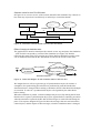
Strategy
The usual tasks of the analysis when producing a system involves analyzing use cases and
creating basic objects from these. This part is not as relevant as it might seem for our
purposes, because we already have a system which to a great extent covers the
functionality specified by the use cases. And where it does not, we must make it. This
approach is more bottom-up as opposed to the more conventional top-down thinking
found in object oriented design, but it is not entirely suitable for our goals either. We want
to adapt the original system to meet with our requirements, but still wish the new part of
the system to be object-oriented and be the product of a higher level of design. To achieve
this we are forced to make a compromise. On one hand we have the original system,
which will be expanded and changed bottom-up, and on the other we have the new part of
the system, which will be object-oriented and designed top-down (see Figure 9). The
integration of these two parts now becomes a new design challenge.
GUI
Additions
HC-Sim
Figure 9.
Integration
Changes
The design strategy of HC-Sim GUI.
Tasks
Our first task in the analysis process is to expand the requirements produced in the
requirements elicitation in order to produce a more concrete view of what is required of
the system. Our remaining tasks then involve a study of the original system and of the
new requirements in order to answer these questions:
•
How does the current system meet with the requirements of the new system?
•
To what extent does the original system support the introduction of the
functionality defined in the requirements elicitation and what changes or additions
need to be made in order to support it?
•
What traits of the original system may become impediments to the new system?
•
How does the original system relate to the functionality described in the use cases
and scenarios, and what is needed to improve its usability?
•
Are there any conflicts involved in the system requirements?
The analysis includes examining the code of HC-Sim in order to see how the program is
constructed and to try to find a general coding strategy and mentality. Being aware of how
problems have been solved in the past is important in order to evaluate the original system
and to make the integration between the new additions and the original system smoother.
The code analysis will also be of great value when we suggest how the system could be
re-engineered more thoroughly at the end of the project.
13
Usability
Program usability
A note on human-computer interaction
The area of human-computer interaction is not the focus of this project. Never the less, it
is the general idea and anticipation of this project that the program will be used, and used
frequently. Taking some time to make the user’s life easier when handling the HC-Sim
GUI program is highly likely to increase its lifecycle. The capability of a program in
terms of usability introduced by a graphical environment was of course one of the reasons
a request to make a graphical user interface was made in the first place. A detailed case
study of the level of usability of the program will not be made, however. These issues will
be dealt with in the design and implementation process, striving towards achieving a
reasonable level of usability and focusing on the most relevant parts.
Interaction
The user of the program should experience that he 5 has control of the program, without
feeling that he must go through a considerable effort to achieve his goals. Each control
device should be clear in its purpose, easily accessible and consistent with other controls
throughout the whole user interface. Because much of the control of the simulation is
placed in the test files used for simulations, the number of controls and settings is
decreased dramatically. Only basic program controls and simulation configuration
mechanisms should need to be supplied by the graphical user interface.
Feedback
The whole purpose of a simulation is to run a test and to view results. The user should not
be distracted by hundreds of blinking lights and have text and dazzling graphics flashed
before his eyes during the simulation process. Still, all relevant data must be able to be
presented and interpreted during and after the simulation at a rate that the user can
manage. Most times it can be assumed that the user is merely interested in one or a few
particular types of data, and therefore some means of controlling what types of data are
presented and how should be provided.
Software usability
The first thing that any software developer should consider when embarking on an
extension project is the fact that many software projects that at first seem promising and
evolutionary end up going straight from the cradle to the grave. A great concern for the
software developer should therefore be whether or not the software will actually be
accepted as something worth using - not only by the user, but by other developers as well.
In the case of the HC-Sim GUI project, the users and the developers are mostly the same
people. Simply trying to impress software developers with visual effects and lots of
features will probably not do the trick, since they are more likely to ask how that affects
program performance or how many lines of source code was required. The developer
wants more than just stunning features, since he has to be able and willing to continue
working with the project without great effort. Here follows a few key ingredients to this
recipe:
5
For the remainder of this report, "he" and "him" should be read as "he or she" and "him or her".
14
•
The environment and tools required should be exchangeable, as well as easy to set
up and to use.
•
All 3:rd party libraries and integrated software used should not be inhibiting to the
any requirements of the project, well documented and easily accessible to
developers, preferably publicly available or open source.
•
The goals and purpose of the project must be well defined.
•
The project must not add any status quo restrictions to the development process of
the extension project or of the base project.
•
The documentation of the project and source code should be adequate for other
developers to be able to follow it. Detailed explanations, where required, are
encouraged.
Imposed requirements
Requirements of HC-Sim GUI imposed by HC-Sim
Portability
For the HC-Sim GUI project, portability is an important issue. Since the original HC-Sim
was designed to be used on different versions of Windows, Unix and Linux, so must
HC-Sim GUI. This imposes an interesting restriction on the choice of programming
language and graphics library. Should this issue be the most important one, a platform
independent language such as Java [20] would make a reasonable choice. To be more
compatible with HC-Sim, however, ANSI-C or C++ should be used.
GUI Performance
The introduction of a graphical environment must not slow down simulations notably.
Particularly when running network traffic through the simulator, a graphics library
requiring much computer resources would most likely either not be able to keep up with
the simulation or make it slower. The overall performance of this graphical version of
HC-Sim must be treated as a priority issue during both the design phase and the
implementation phase.
Integration
It seems inevitable to make some changes and additions to the original HC-Sim code for
the sake of this project. However, in order to allow HC-Sim to be developed
independently of HC-Sim GUI, additions and changes to the HC-Sim code should be kept
at a minimum. Furthermore, it must be possible to compile the original version of HC-Sim
without any graphics when testing and running on machines with little resources. This
suggests that all code that is added to HC-Sim for the sake of this integration should be
detachable in some way. The original version of HC-Sim should still be able to be
compiled, completely independent and unaffected by the addition of any graphical user
interface.
Do not edit the products
The Effnet software products (IPHC, CRTP, ROHC) should not be affected by the
integration of HC-Sim and HC-Sim GUI 6. Also, the software products used by HC-Sim
are designed to be compiled with ANSI-C, and making them for instance C++ compatible
would require changes that may affect their performance and functionality.
6
This restriction was added late in the project. My original plan was to make the header
compression libraries compile with a C++ compiler as well.
15
Requirements of HC-Sim imposed by HC-Sim GUI
Language compatibility
The source code of HC-Sim must be kept C++ compatible. The main reasons are
simplified integration of HC-Sim and HC-Sim GUI, and the ability to throw exceptions
upon error (see Choice of programming language, page 45). Note that this restriction also
works the other way around, since HC-Sim should still be ANSI-C compatible.
Integration code
HC-Sim must include (detachable) code to interact with the GUI in order to store precise
simulation data, and to allow user interaction through the user interface to affect the
simulation.
Cleanup and reset
The original HC-Sim philosophy was run once, cleanup is done automatically when the
program exits. This may be true, to some extent, when running the program once per
simulation. Through the GUI, however, an arbitrary number of simulations are run for
each program session. After each simulation, all files and handles must be closed, and
memory on the heap must be freed. Before running the next simulation, all stateful data
must be reset to initial values.
Merging the requirements
It comes as no great surprise that many of the requirements mentioned are in direct
conflict with one another. Whereas for some of them the requirements imposed by
HC-Sim and those imposed by HC-Sim GUI may be compromised, some of them may
not. Creating a spin-off version of HC-Sim for the sake of integrating it with a GUI is one
way to handle these conflicts. Another solution is to make the program compile one way
when a GUI is present and another way when it is not. In the light of the requirement that
as little code as possible should be added to HC-Sim anyway, the latter would seem
feasible and also more reasonable than creating a whole new project.
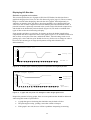
Analyzing the feedback
Displaying statistics
Displaying statistics with printlines
In the command-line based version of HC-Sim, each packet whose IP-header has been
compressed or decompressed results in a simple printout to the console. The print includes
the source of the packet along with a short description of the IP-header structure, followed
by an extract of the first bytes of data of the unit. For special events, such as when a
packet is lost, damaged or cannot be decompressed, a warning message is also printed. A
summary of the statistics and results of the simulation are not displayed until the
simulation has been completed. The summary covers information about how long the
simulation was run, how the compression turned out, and how many packets were restored
or failed (see HC-Sim test-run excerpt below).
One obvious flaw of this way of presenting data is the flow of the data itself. Because
packets are generally handled at a rate that by far exceeds a normal human being’s ability
to read, the data will never be interpreted, and hence it has no informational value. And
even if the user would manage to read the printout, for instance by slowing down the
packet rate or printing the output to a file, he would not be able to get a clear view of what
is going on. The reason is that the massive load of data does not yield a structured
overview of the simulation status. The main problem is that the summary is not printed
16
until at the end of the simulation, when what is really needed to understand the process is
a continuous presentation of the data. This is difficult to achieve with printouts, as large
quantities of continuous text output only makes the data flow harder for the user to grasp.
excerpt from an HC-Sim test-run showing a summary of simulation statistics)
0 packets delivered to Sink B, 0 errors.
IPHC stats (Charles):
Full headers sent:
7
Compressed headers sent:
Unmodified headers:
0
Unknown packets:
Bytes before compression:
952
Bytes after compression:
Header requests received:
0
Full headers decompressed:
0
Comp headers decompressed:
Packets dropped by decompressor:
0
Packets with bad TCP checksums:
24 packets delivered to Sink A, 0 errors.
IPHC stats (Diana):
Full headers sent:
0
Compressed headers sent:
Unmodified headers:
0
Unknown packets:
Bytes before compression:
0
Bytes after compression:
Header requests received:
0
Full headers decompressed:
4
Comp headers decompressed:
Packets dropped by decompressor:
5
Packets with bad TCP checksums:
27
0
304
0
0
0
0
0
20
0
Displaying statistics in the GUI
With a graphical version of HC-Sim, the problems with the presentation of data in the
command-based version can be solved. By presenting compression ratio, data flow, error
rates and packet flows with graphs, the user can actually get an overview of how the
simulation turns out. It also helps the user to keep track of what is happening right now
and what has happened before, providing a greater picture of the turnout. Easy
comparison of data between different simulations also becomes possible, in particular if a
way of saving the data between simulations were to be provided.
Data analysis
What information do we need to extract from HC-Sim in order to make an accurate
presentation? It seems logical that because we are simulating header compression, the
most crucial types of data are those directly related to the packet flow, the compressor and
the decompressor. Looking at the scenarios and use cases we see different aspects of the
simulation, and so we must consider what data may be classified as interesting from these
viewpoints.
Interesting simulation events
The events we are interested in may be different depending on which compression scheme
is being used, but for all schemes we should at least consider the following events:
•
An uncompressed packet is received
•
An IP header is compressed
•
A compressed packet is sent
•
A compressed packet is received
•
An IP header is decompressed
•
An uncompressed packet is sent
•
A packet is dropped
17
Statistical data
Statistical data are available in data structures of HC-Sim, but these data are not directly
related to either simulation events or time. It is simply a collection of accumulated values
for each piece of statistic. For instance, is difficult to draw a graph from just knowing the
total number of IP headers compressed or the total number of bytes before compression.
To do that we would need to have detailed information about each separate event. The
event of compressing a header should be associated with a time stamp, the type of the
header compressed, the number of bytes before compression, the number of bytes after
compression, or an error flag should the compression have failed. A code excerpt showing
the declaration of the IPHC statistics struct follows here.
excerpt from source code file eff2507c.h)
/**
* @brief The statistics of the compression is stored in this struct.
*/
typedef struct iphcStat {
i32_t v6s_full_c;
/* Number of full headers produced by the compressor */
i32_t v6s_comp_c;
/* Number of compressed headers produced by the compressor */
i32_t v6s_unmod_c; /* Number of unmodified headers produced by the compressor */
i32_t v6s_bbefore_c;
/* Total number of bytes before compression */
i32_t v6s_bafter_c;
/* Total number of bytes after compression */
i32_t v6s_changes_c;
/* Not used */
i32_t v6s_unknown_c;
/* Number of packets that were unknown or caused errors */
i32_t v6s_full_d;
/* Number of full headers decompressed */
i32_t v6s_comp_d;
/* Number of compressed headers decompressed */
i32_t v6s_unmod_d;
/* not used */
i32_t v6s_dropped_d;
/* Number of packets dropped by the decompressor */
i32_t v6s_badsum_d;
/* Number of packets with bad checksum */
i32_t v6s_head_req_revc;/* Number of header requests received */
} IphcStat_t;
The information available alone is not enough to make a detailed graphical presentation.
HC-Sim GUI should provide a way of associating relevant statistics with separate events
and/or, with simulation time so that a study of the simulation can be made on a per event
basis rather than on a per simulation basis. This implies that either HC-Sim must report
each simulation event to HC-Sim GUI, or store information about each event for later
acquisition. Alternatively, HC-Sim GUI could check the statistics periodically and
compare new statistics with old statistics to find out what has happened since the last
time. These issues will be dealt with in the Information management section (page 30).
General simulation information
Being able to look at details of the simulation data is the most important feature to a user,
as well as the reason for having a simulator in the first place. But for the simulation to
make sense to the operator and the spectator, the program must provide information about
the simulation itself. HC-Sim GUI should provide information about the simulator’s
current state and progression, time since the simulation started and the time at which the
simulation will finish. HC-Sim keeps track of this information, but does not have the
means to display this information continuously, since the only means of presenting it is
through printouts. Trying to print all of this information to the screen will only make data
flash before the eyes of the user without providing any usable information.
18
Program control
Controlling the simulation
HC-Sim provides no built-in way of controlling a simulation once the program has been
started. Some basic shell commands can of course be used to achieve a small level of
control, but these controls are not of any practical value when running a simulation with a
GUI (see Table 2). The original version of HC-Sim has no need for advanced simulation
controls, due to the fact that only one simulation is run per program session. As a program
with a graphical user interface takes longer to start up, the program can not be expected to
start and exit at each single simulation session, and hence at least basic controls (run and
stop) must be provided to control the simulations.
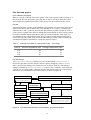
Table 2.
Simulation controls in HC-Sim with and without a GUI.
Command
HC-Sim without GUI
HC-Sim with GUI
Run simulation
Automatically when starting program
Press "run"
Pause simulation
Hit the "Pause" key on the keyboard
Press "pause"
Resume simulation
Hit the "Return" key on the keyboard
Press "run"
Stop simulation
Kill the process
Press "stop"
Configuration
Program parameters
Each HC-Sim simulation requires a simulation setup through a command line, which is
passed in as program parameters. Valid configurations are explained in the HC-Sim user
manual [10], and briefly in the help text that is displayed when the –help switch is passed
as a program parameter. The program does not provide any other hints on how the user
should input the parameters, nor does it have any means of placing restrictions on the
contents of the parameters to avoid a misconfiguration. An incorrect configuration results
in a program stack dump, and a short error message on what went wrong.
The graphical user interface should help the user to produce valid configurations, by
making suggestions or restricting the input to valid configurations. If an error should
occur due to a bad input, then the simulation will not run, but the program will continue
execution as normal and display a helpful error message.
Compile-time configurations
Because HC-Sim compiles relatively fast, it can rely on values defined at compile time to
produce HC-Sim executables with different configurations. These configurations include
among others Ethernet support, network support, internal developer configurations and
debugging facilities. Some of these configurations, those controlling program trace lines
in particular, should be able to be made by a user at run-time instead of being defined by a
developer at compile-time. This would enable them to be turned on or off at will, making
the user able to focus on certain trace lines and not be bothered by others. Furthermore,
HC-Sim GUI cannot be expected to compile and be linked as efficiently as HC-Sim, due
to the fact that it has much more code and makes use of graphical libraries. Re-compiling
the program just for the sake of controlling these trace lines would neither be optimal nor
desirable.
19
System design
Meeting with the requirements
General guidelines
It is evident that this project requires that some changes be made to HC-Sim. However,
these changes should not affect HC-Sim’s capacity for running as a command based
program without a GUI, and they should be kept small and neat, not to crowd the original
HC-Sim code with functionality that is not needed unless an graphical user interface is
present. Less is more, as they say, and the more complicated code we add to HC-Sim, the
less are the chances that the HC-Sim developers will embrace them.
Design goals
The program structure makes a clear distinction between what components are related to
the HC-Sim side or the HC-Sim GUI side only, and what components are related to both
of these. The graphical user interface provides the user with all the means necessary for
configuring and controlling simulations, as well as enabling presentation of both
simulation progress and simulation data graphically and/or numerically. Depending on
what type of data is interesting to a user in a certain situation, the program should also
enable him to focus on that data.
Developers of HC-Sim must be able to understand the program and follow in the footsteps
of this project. For this reason it is important that we aim at creating a good foundation
and program structure. Having several related small components forming a whole is better
than having a large pile of code.
20
GUI as a front-end or as integrated software
Front-end
What signifies a front-end is that the user interface itself is one program, and that the user
interface and the program to be controlled run as separate processes (see Figure 10 and
Figure 11). This would of course limit the level of integration with the software to be
controlled, as no data or functions are shared between the user interface implementation
and the application to be controlled. Extracting information from the application would
then require parsing data produced by the program from standard output, and the level of
control of the application during execution would virtually be non-existent.
Integrated user interface
An alternative to using a front-end is to merge HC-Sim and the GUI into one big program,
even though we try to keep a clear distinction between what belongs to the GUI side and
what belongs to the HC-Sim side. To achieve this, global data should not be shared
between the two parts, and all interaction should be made explicitly through function
calls. There should also be a clear line between the two entities, which may be realized
through interface files that declare the functionality available to or that should be
implemented by the other part. Also, the physical connection in the code, the
implementation of this functionality, should be clear and consistent with these interfaces.
For ease of future changes, in which the functionality and structure of HC-Sim is likely to
change, the data structures and functionality of HC-Sim used in HC-Sim GUI should be
encapsulated in classes and objects, and never used directly.
Threads
In order for the graphics of HC-Sim GUI to function during a simulation, it will be
necessary to have at least two threads: one for handling the graphical user interface and
one for simulations (see Figure 12). If we were to use a single thread of execution, then
the GUI would not work during a simulation. The interaction between and
synchronization of these two threads now becomes an issue that must be addressed.
Which one to choose
What motivates the design of a front-end GUI is the low level of integration. The user
interface can be created almost independently of the application. At the beginning of the
project, this approach may help distinguishing the user interface from the application,
which is one of the design goals. However, in order to achieve the level of user control
and information management that we aim for, the user interface should be able to directly
invoke functions of and acquire data from HC-Sim. Keeping the original program
unchanged, and still being able to achieve the same result, is not possible. Logically, we
will therefore start by designing the GUI as a front-end, but then move on to integrating it
with the original program, in order to further increase the level of user interaction and the
richness in and variety of the data.
21
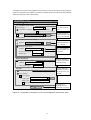
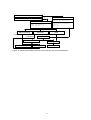
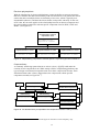
Flow of execution events
HC-Sim with no GUI
Start
HC-Sim process
main(int argc, char *argv[])
•
•
Invoke parse_params
Invoke init_hcsim
parse_params(int argc, char *argc[])
•
Parse HC-Sim commands and parameters
init_hcsim()
•
Prepare and start simulation
Figure 10. HC-Sim with no GUI runs in a single- threaded process.
HC-Sim with GUI as an independent front-end
Start
HC-Sim GUI process
HC-Sim process
main(int argc,char *argv[])
main(int argc,char *argv[])
•
•
Invoke init_GUI
Call exec: HC-Sim when user
presses ”run” button or menu
item
init_GUI(int argc,char *argv[])
•
•
Parse GUI specific parameters
Create and paint GUI
•
•
Invoke parse_params
Invoke init_hcsim
parse_params(int argc,char *argc[])
•
Parse HC-Sim parameters
init_hcsim()
•
Prepare and start simulation
Figure 11. The HC-Sim GUI process creates another process to execute HC-Sim.
HC-Sim with GUI as integrated software
Start HC-Sim GUI thread
main(int argc,char *argv[])
• Invoke init_GUI
•
•
•
HC-Sim thread
init_hcsim()
Wait for user to press "run" button
Invoke get_params
Invoke HC-Sim: init_hcsim()
•
•
Initialize simulation
Start simulation
init_GUI(int argc, char *argv[])
•
•
Parse GUI specific parameters
Create and paint GUI
get_params()
•
Acquire HC-Sim parameters from user
settings in GUI, check for errors
Figure 12. HC-Sim GUI thread and HC-Sim thread running in the same process.
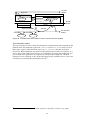
22
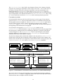
Interaction between HC-Sim and HC-Sim GUI
As the word interaction implies, we need to define the relationship between the HC-Sim
side and the HC-Sim GUI side in terms of actions. Some aspects of this relationship are
naturally related to the main responsibilities of the HC-Sim side and the HC-Sim GUI
side.
HC-Sim side:
HC-Sim GUI side:
run simulation, provide statistics
control simulation, present simulation data
With these basic responsibilities in mind we design interfaces corresponding to each side:
a control interface, which is used by the HC-Sim GUI side to control the HC-Sim side,
and a callback interface, used by HC-Sim to report back to and access functionality of
HC-Sim GUI (see Figure 13).
Invokes
HC-Sim callback
interface
HC-Sim control interface
Implements
Implements
Invokes
HC-Sim with
IPHC / CRTP / ROHC
HC-Sim GUI with
IPHC / CRTP / ROHC
Figure 13. The relationship and interaction between the HC-Sim side and the
HC-Sim GUI side.
HC-Sim control interface
The HC-Sim control interface is an abstraction of the functions of HC-Sim invoked by
HC-Sim GUI to control simulations. It consists of these header files:
File name:
Purpose:
hcsim_main.h
Configure and run HC-Sim
hcsim_trace.h
Control HC-Sim trace lines
The functions used are few and simple: initialize simulation, start simulation, control the
output. As there is no way of stopping a simulation in the original version, except by
killing the process, we let this functionality be handled through callbacks instead.
HC-Sim callback interface
The control interface provides no means of communication between HC-Sim and HC-Sim
GUI during a simulation. In order to maintain control of the simulation and to acquire
precise data, HC-Sim can make callbacks to HC-Sim GUI to reports events and states.
The callback functions are declared in the header file hcsim_callback_interface.h
[Appendix B]. The functions are listed in Table 3.
23
Table 3.
Function declarations available in the HC-Sim callback interface.
Function declaration
Purpose
hcsim_callback_report_started
(hcsim_callback_time_t*)
hcsim_callback_report_finished
(hcsim_callback_time_t*)
Reports back when a simulation has
started.
Reports back when a simulation has
finished.
hcsim_callback_event
(hcsim_callback_event_t,
hcsim_callback_event_parameter_t*)
Called when a simulation event has
taken place.
hcsim_callback_poll_keep_running Called to check whether the user has
(hcsim_callback_parameter_t*)
stopped the simulation.
Polling
During a simulation, HC-Sim handles a growing queue of small and separate events.
Between each event, the simulator polls HC-Sim GUI to check if the simulation has been
stopped prematurely. Using callback functions to poll the user interface for this
information is not the most efficient way to go about it. There are other ways to handle
this interaction, for instance by using signals and messages between threads. The
advantage of using polls is the simplicity of design and implementation, but one should
keep in mind that a considerable number of polls might be made during the course of a
simulation.
Simulation event callbacks
In the analysis process we stated that the functionality for providing rich information
about simulation events could be placed within HC-Sim or it could be placed externally.
The latter provides more flexibility, and adds less code to HC-Sim, and so it seems like
the best solution for our purposes.
By making HC-Sim report back to HC-Sim GUI each time an interesting event has
occurred, HC-Sim GUI can acquire the information needed to make a correct graphical
presentation and to show the current status and progress of HC-Sim. At the same time, we
eliminate the need for HC-Sim to maintain event related statistical data that would add
complexity and unnecessary quantities of code to the simulator. The callback events and
flow of data will be explained further in the Information management section (page 30).
24
Thread interaction
Two threads must be used in the HC-Sim GUI application. One thread for controlling the
graphical user interface and presenting data, referred to as the HC-Sim GUI thread, and
one thread for running the simulation and gathering statistical data, referred to as the HCSim thread. During a simulation, the former must only use functionality available on the
HC-Sim side, which consists of the HC-Sim source code and the HC-Sim callback
interface. The latter will use only the functionality available on the HC-Sim GUI side,
which is all HC-Sim GUI source code and the HC-Sim control interface.
There are several functions available to the HC-Sim side through the callback interface,
all of which are implemented by the HC-Sim GUI side. To simplify matters it is wise to
keep these function implementations in a single source file, which we here name
hcsim_gui.cpp. The corresponding header file hcsim_gui.h will then contain
declarations of the functionality available to the HC-Sim GUI side, and is not available to
the HC-Sim side. This construction works as a bridge between the two sides, as is shown
in Figure 14.
HC-Sim side
Is available to
hcsim_callback_interface.h
hcsim_gui.h
Is available to
HC-Sim GUI side
Implements
functionality of
hcsim_gui.cpp
Figure 14. Implementation of a bridge between the two sides of HC-Sim GUI.
The most interesting interaction aspect is that of HC-Sim statistics acquisition and
processing. As one thread gathers information, and the other handles it, it is clear that
some sort of synchronization of the threads is needed for this process. This process must
be examined thoroughly.
HC-Sim thread of execution
This thread runs in special thread function, which has access to the GUI objects required.
The thread could be created when a simulation is to start, or it could be created once and
re-used, in which case it must only run when signaled through some synchronization
object. During a simulation, this thread will not access any graphical components to
display data, but rather store information in some data structure of hcsim_gui.cpp and let
the other thread worry about showing it. Adhering to the policy of polls described earlier,
the thread also must check if the simulation has been interrupted between simulation
events. The state chart diagram in Figure 15 demonstrates the general chain of events.
25
Closing application
Start
Die
Wait for simulation to be started:
stand by for sync object signal
Signalled
Prepare simulation
Display error message to user
through the GUI
Close files and clean
up after simulation
Error in simulation
Misconfiguration
Run simulation
Figure 15. State chart diagram for the execution of the HC-Sim thread.
Running the simulation
Figure 16 contains a more detailed state chart for running the simulation, focusing on the
callbacks. It shows how the callback interface may be used to report events and to poll the
external user interface as to whether the simulation is to keep on running. The term event
here refers to some representation of those events that would be relevant for a simulation
from an external point of view, and not to each detailed event that may occur within the
simulator.
Examples of relevant events:
a header is compressed, a packet is dropped, a packet is sent.
Examples of non-relevant (internal) events:
increase simulation time, a channel delay is inserted, check for incoming packets
We could also let the user decide which of these relevant events are actually relevant to
him during a particular simulation by, for each event, having some sort of flag that may be
controlled through the graphical user interface.
Start
Signalled
Paused: stand by
for un-pause signal
Paused
Callback: report
simulation started
Callback: poll
simulation status
Get next event
Callback:
report event
Stopped
Callback: report
simulation finished
No more
events
Handle event and
store statistics
Event has
statistical relevance
Figure 16. State chart diagram showing callbacks made by the HC-Sim thread in a
simulation.
26
HC-Sim GUI thread of execution
This thread is not equal to the HC-Sim thread, in the sense that it depends on it. Because
the HC-Sim GUI thread is responsible for handling all user interaction, such as starting
and stopping simulations, it is the responsibility of this thread to control the other. The
HC-Sim thread, on the other hand, has no interest in knowing what point of execution the
GUI thread is currently at. The general states of the GUI thread are shown in the state
chart diagram of Figure 17. We assume that the HC-Sim thread exists prior to entering the
first state and terminates when leaving the last state.
We mentioned earlier that the GUI thread is responsible for displaying statistics
graphically, but this thread can still not dedicate all of its time to handling and presenting
statistics. All GUI related tasks such as repainting the user interface and handling user
interaction through menus and buttons must also be performed regularly. The state in
which this is done is referred to as "perform regular GUI tasks" and it must be entered
between all time-consuming tasks or the graphical user interface will not work correctly
or not be repainted often enough. One way to achieve this is to let time-consuming events
such as parsing statistics be made periodically by using a timer, giving the graphics time
to be painted before new ones arrive. Also, timeouts could be used when performing these
tasks to make sure that the graphical user interface tasks are not neglected.
Schedule repaints
Simulation
running
Check simulation status
Process statistics
No new statistics
Add timeout for
statistics processing
Check for new statistics
Signal to HC-Sim thread
that simulation should start
Die
“Run” pressed
Perform regular
GUI tasks
Closing
application
Timeout for statistics
processing
Start
Figure 17. State chart diagram for the execution of the HC-Sim GUI thread.
27
Simulation controls for the HC-Sim GUI thread
In Figure 18 we see an overview of the controls that affect the simulation. By controls we
here mean any object that is used directly or indirectly to control the threads.
pauseSync
Object
SimulationStatus
1
1
HCSimGUI
1
1
1
startSync
Object
<<instanceof>>
<<instanceof>>
2
ThreadSynchronizationObject
1
1
StatisticsProcessingTimer
GraphicalUserInterface
Figure 18. Simulation controls related to the HC-Sim GUI thread.
Effects of changing the simulation status
The graphical user interface should provide controls to run, stop and pause the simulation
– each of which corresponds to a status of the simulation (see Figure 19). Besides
reflecting this status in the GUI, pressing one of these buttons should also result in some
sort of communication with the HC-Sim thread in order for the action to take effect.
"Pause" pressed
Start
Simulation not
yet started
"Run" pressed
"Run" pressed
Running
Paused
"Stop" pressed
"Stop" pressed
Stopped
Simulation finished
Figure 19. State chart diagram for the simulation status of HC-Sim GUI.
We imagine that we will use a general type of synchronization object (for instance a
semaphore) for synchronizing the tasks that are performed by each thread when the
simulation status is changed. When starting a simulation, the HC-Sim thread should begin
its execution. It waits for a synchronization object to be signaled by the other thread
before starting.
When the simulation is paused, a similar technique may be used. By making the HC-Sim
thread wait for a pause-synchronization object to be signaled before continuing execution
when the simulation is paused, the HC-Sim GUI thread gets to work full-time during the
pause. The sequence diagram in Figure 20 shows the messages that are sent between the
control objects, and the impact of these messages, when the simulation status is changed.
28
:GUI :simulation :start
:pause
:statistics
Status
SyncObject
SyncObject
Processing
:hcsimGUIuser
Timer
pressRun()
running()
signal()
start()
pressPause()
pressRun()
pressStop()
paused()
running()
signal()
stopped()
stop()
time
Figure 20. Sequence diagram for changing the status of a simulation.
Passing parameters to HC-Sim
The command-line based version of HC-Sim takes as parameter to its main function an
array of simple C-strings7, which contains the command that was entered in the console.
The strings are parsed and checked for errors before the initialization of the simulator can
be made. Considering the amount of code required for parsing parameters and making this
verification in HC-Sim, the graphical version does not need to provide its own methods
for doing this.
By making use of the existing parameter parser in HC-Sim, the GUI becomes less tightly
integrated with the original system. The GUI needs only to conform to the command-line
syntax of HC-Sim to produce syntactically correct simulation configuration parameters. A
vector of strings is simply generated from the current GUI configuration when the user
presses the "Run" button, and is then passed to HC-Sim, which handles the parsing. This
strategy has more in common with the front-end design of Figure 11 than with the more
integrated user interface design of Figure 12 (page 22), which is a direct result of our
disinclination towards making the GUI tightly integrated with HC-Sim.
7
By C-strings we mean arrays of type char
29
Information management
Simulation statistics
HC-Sim data structures
Since each compression scheme used by HC-Sim is unique in many aspects, the statistics
that are stored for each scheme are quite different. Some general traits are common for the
IPHC, CRTP and ROHC (particularly between the first two), while others are only
applicable to one of them. Table 4 and Table 5 give us an overview of the data that are
available in the statistical data structures for each scheme. The particular types of
statistical data do not represent what is important here. What matters are the differences
regarding available information for the three compression schemes.
Table 4.
Statistics available at the compressor for each compression scheme.
Compressor statistics trait
Total bytes before compression
Total bytes after compression
Number of packets produced
Number of compressed headers produced
IPHC
Number of full headers produced
Number of unmodified headers produced
Number of packets failed
Number of header requests received
Number of ACKs received
Number of negative ACKs received
ROHC
n
n
n
n
n
n
n
n
n
n
n
n
n
n
n
n
n
n
n
n
N/A
N/A
N/A
n
N/A
N/A
n
N/A
N/A
n
N/A
N/A
n
N/A
N/A
n
n
Number of static negative ACKs received
Number of initializations/refreshes produced
Number of non initializations/refreshes produced
Table 5.
CRTP
Statistics available at the decompressor for each compression scheme.
Decompressor statistics trait
Number of packets received
Number of compressed headers restored
Number of full headers restored
Number of unmodified header restored
Number of RTP packets restored
Number of UDP packets restored
IPHC
Number of packets with bad checksum
Number of packets failed to decompress
Number of header requests sent
Number of ACKs sent
Number of negative ACKs sent
Number of static negative ACKs sent
n
CRTP
n
ROHC
n
n
n
n
n
n
n
n
30
n
n
n
N/A
N/A
N/A
n
N/A
N/A
n
N/A
N/A
n
The way the statistics are organized also differs between the compression schemes.
ROHC separates compressor statistics from decompressor statistics by placing them in
separate data structures, while IPHC and CRTP do not. Another ROHC specific trait is to
identify the statistics by using the channel id, which is a unique identifier for the
connection between a compressor and a decompressor. IPHC and CRTP identify the
statistical data by associating them with either the Charles side or the Diana side. This
difference is quite subtle, as the identifiers convey the same information.
Encapsulating the differences
In order to make HC-Sim GUI less influenced by the structural differences of the
statistical data structures, we design a class named HCSimStatistics to wrap the data
and provide us with a common interface (Figure 21) to the statistics.
ROHC
HCSimStatistics
comp_stats_t
HC: comp_stats_t/Crtp_Stat_t/Iphc_Stat_t
decomp_stats_t
DC: decomp_stats_t/Crtp_Stat_t/Iphc_Stat_t
CRTP
Crtp_Stat_t
IPHC
Iphc_Stat_t
hcNumberOfPacketsProduced_compressedHeaders()
hcNumberOfPacketsProduced_fullOrUnmodifiedHeaders()
hcNumberOfPacketsFailed()
hcBytesBeforeCompression()
hcBytesAfterCompression()
dcNumberOfPacketsRestored()
dcNumberOfPacketsRestored_compressedHeaders()
dcNumberOfPacketsRestored_fullOrUnmodifiedHeaders()
dcNumberOfPacketsFailed()
Figure 21. Data structures for statistics wrapped in class HCSimStatistics.
The information that is common to all compression schemes can now be accessed through
the access functions of the wrapper class. For compression scheme specific data, such as
for instance the number of header requests received, we can create access functions that
only apply when that specific compression scheme is defined. The code of HC-Sim
already has a technique for doing this, which relies on C pre-processor macro constants
defined at compile time to determine which compression scheme is used - USE_IPHC,
USE_CRTP or USE_ROHC. The code example below demonstrates how they may be used
in class HCSimStatistics.
example)
#if USE_IPHC | USE_CRTP
unsigned int hcNumberOfHeaderRequestsReceived();
#endif
The function declaration above is hence only available when IPHC or CRTP compression
is used. This type of solution works well when only one compression scheme at a time is
used in HC-Sim, which is currently the only legal compile time configuration. We will
return to this issue in the discussion on how HC-Sim could be re-engineered at the end of
the project (see There can be only one, page 74).
31
Event related statistics
In Table 3 (page 24) we saw that the HC-Sim callback interface contains the following
function declaration:
hcsim_callback_event(hcsim_callback_event_t,
hcsim_callback_event_parameter_t*)
This function is what makes event related simulation statistics available to the GUI. Each
event that is relevant to HC-Sim GUI from a statistical point of view (see
Running the simulation, page 26) is associated with an event type in the callback interface.
Here follows some examples from the file hcsim_callback_interface.h.
#define
#define
#define
#define
#define
#define
#define
HCSIM_EVENT_TYPE_HEADER_COMPRESSED
HCSIM_EVENT_TYPE_HEADER_DECOMPRESSED
HCSIM_EVENT_TYPE_PACKET_SENT
HCSIM_EVENT_TYPE_PACKET_RECEIVED
HCSIM_EVENT_TYPE_EXTERNAL_PACKET_RECEIVED
HCSIM_EVENT_TYPE_EXTERNAL_PACKET_SENT
HCSIM_EVENT_TYPE_PACKET_DROPPED
0x00000001
0x00000002
0x00000004
0x00000008
0x00000010
0x00000020
0x00000040
An event type together with other event classification data form an event code, whose
structure is shown in Table 6.
Table 6.
Bits
The structure of the HC-Sim callback event code.
Category
31 – 29 Header compression scheme (IPHC, CRTP, ROHC)
28 – 27 Simulator side (Charles or Diana)
26 – 22 Logical class of the event (compressor, decompressor, channel, …)
21 – 0
Event type (header compressed, header decompressed, packet sent, …)
Note that the structure of the event code bears some resemblance to the fields of an
IP header. The idea behind this design was simply to make event classification easy, but
future implementations might use this feature for passing event messages in more
sophisticated ways, for instance wrapped in IP/UDP datagrams 8.
The bits of the event code also have one important feature: each bit is associated with
precisely one piece of information. This way we can create codes that represent more than
one type of event at once, such as for instance decompressing a header and then
immediately dropping the packet because is was duplicated. This type of event code usage
was also mainly intended for more sophisticated future implementations, and will not be
applied in this project. Another advantage of the one-bit-per-piece-of-information
approach is that is makes forming event codes very easy by making bit wise OR of each
part of the event code, in which the order of the different parts becomes irrelevant.
example)
int event_code = HSIM_EVENT_SCHEME_ROHC|HCSIM_EVENT_SIDE_CHARLES|
HCSIM_EVENT_CLASS_HC|HCSIM_EVENT_TYPE_HEADER_COMPRESSED
After forming an event code like in the example above, the event code is used as a
simulation event representation that is passed from the HC-Sim side to the HC-Sim GUI
side through the function hcsim_callback_event of the callback interface (as a
8
This is just a wildcard idea for the future. Maybe in a distributed version of HC-Sim, or in a
version of HC-Sim GUI in which the simulator and the graphical user interface run as separate
processes.
32
parameter of type hcsim_callback_event_t). In Figure 22 we see how a callback
event is associated with an HCSimStatistics object, which is stored in an
HCSimStatisticsQueue managed by class HCSimGUI. The callback interface
implementation receives the code for the event, along with any event related data, creates
an instance of class HCSimStatistics, and stores the event code and a snapshot copy of
the statistics struct at the time of the event callback in that object. The
HCSimStatistics object is then put in a statistics queue associated with either Charles
or for Diana, depending on the event side value of the event code.
HCSimStatistics
HC-Sim GUI side
hcsim_callback_event(…)
event code,
event related data
HC: <compressor statistics>
DC: <decompressor statistics>
time: hcsim_callback_time_t
code: hcsim_callback_event_t
storeStatistics(hcsim_callback_event_t)
*
2
HC-Sim side
make event callback
HCSimStatisticsQueue
statisticsQueue: Queue
push_back(hcsim_callback_event_t)
HCSimGUI
getCallbackStatisticsQueue(hcsim_side_t)
1
<<instanceof>>
statisticsQueueCharles
<<instanceof>>
statisticsQueueDiana
Figure 22. Upon a callback, a HCSimStatistics object is stored in a
HCSimStatisticsQueue.
Information extraction
An instance of class HCSimStatistics associated with an event code and a time stamp
provides much more information than the single statistic structure instance that is used by
the original version of HC-Sim. A plain statistics struct merely contains data that indicate
what has happened so far in the simulation – an accumulated view of the information,
while the former can be used to convey both an event specific view and a time specific
view of the simulation data. Each instance indicates what happened, when, and where.
This information enables us to answer simulation related questions such as:
•
How many packets had been compressed when the simulation had run for 2.4
seconds?
•
How many packets were dropped by the decompressor between the time of the
first packet being lost and the time at which the decompressor received a
refreshed IP header context?
•
How much time passes between IP header requests as an average?
Extracting information from snapshots of statistics
The statistics structure copy that is stored in each instance of class HCSimStatistics
itself does not provide us with the information needed to answer the last two of the
questions above, because it is only a reflection of the accumulated statistics of a
simulation at a certain point in time. For the same reason that it takes two points to form a
line, it takes two statistics instances to acquire the changes in statistics. To extract the
desired information we produce a difference view of the statistics at the time of one event
33
and the time a previous, which is done by simply subtracting an object associated with an
earlier event from an object associated with a later event. The new delta-statistics instance
can now tell us what we need to know in order to answer all of the questions above.
To picture the process, Figure 23 shows an instance of class HCSimStatistics
containing the difference in statistics between two HCSimStatistics objects separated
in time.
HCSimStatistics
1
copy(HCSimStatistics)
subtract(HCSimStatistics)
2
<<instanceof>>
deltaObjectAB
sim_time:
bytesBeforeHC:
bytesAfterHC:
n_compressed:
0.14
42
6
1
1
2
objectB
objectA
sim_time:
bytesBeforeHC:
bytesAfterHC:
n_compressed:
0.48
40936
4120
974
sim_time:
bytesBeforeHC:
bytesAfterHC:
n_compressed:
0.62
40978
4126
975
Figure 23. Difference in statistics between two instances of class HCSimStatistics.
Simulation identifier
To facilitate comparisons of statistics between different simulations9 and to keep track of
what objects are associated with which simulation, we need to be able to uniquely identify
each instance of class HCSimStatistics. For this reason a simulation generation
identifier key is associated with each object that is created in the course of a simulation.
The identifier is simply an integer that is increased each time a new simulation begins.
Assuming that only one event at a time can take place in the simulator, we are now able to
identify any instance of class HCSimStatistics first by its generation number and
second by the simulation time at which the statistics were acquired. Should ever more
than one simulation event be allowed to occur at the same time, the event code could be
used to find out which of the events logically took place first. This could be achieved by
knowing, for instance, that a packet must be received over a channel in the simulator
before it can reach the decompressor.
9
Inter-simulation comparisons are not covered by this project, but intended for future
functionality.
34
Plot data and graphs
From statistics to graphs
While it is the job of the HC-Sim side to gather event related statistics and store them, it is
the job of the HC-Sim GUI side to parse the data in order to transform them into a form
more suitable for graphical presentation. This process will be examined in this section.
Plot data
A plot data instance is simply an intermediate representation of a point and an interval in a
graph, which means that it contains data corresponding to an x- and a y-coordinate and
optionally an x- and a y-interval. Several plot data instances together can then be used to
create a plot in a graph. Note that even though this representation of data is closely related
to actual coordinates that are painted in a graph, no actual coordinates in the form (x,y)
are contained in this representation. Only when a graph is actually being painted with a
certain line type, line width, zoom factor and other settings can the actual coordinates be
calculated. Examples of plot data for a graph are shown in Table 7.
Table 7.
Example of plot data for a Compression ratio – Time graph.
Time (s)
Recent compression ratio Average compression ratio
0.22
0.46
0.68
.88
.94
.00
.88
.91
.61
Plot data manager
An HCSimPlotDataManager handles the task of transforming HCSimStatistics
objects into plot data. Just like with the statistics queues managed by class HCSimGUI,
there is one plot data manager for Charles and one for Diana. Each plot data manager
manages a number of HCSimPlotDataVector objects, each of which is associated with
a plot in one or several graphs, containing the plot data instances that are created during a
simulation. The relationship between these classes is shown in Figure 24.
HCSimStatisticsQueue 2
getCallbackStatisticsQueue(hcsim_side_t)
pop_front()
pop_front_diff()
*
HCSimStatistics
<<abstract>>
HCSimPlotData
HCSimGUI
1
<<abstract>>
HCSimGraph
paintData()
1
1
HCSimGUIStatisticsWindow
*
periodic_timeout()
*
1
<<abstract>>
HCSimPlotDataContainer
getPlotData(index_t)
ConcretePlotData
* HCSimPlotDataVector *
1
2
HCSimPlotDataManager
update(
HCSimStatistics stats,
HCSimStatistics diff)
Figure 24. The relationship between HC-Sim statistics, plot data and graphs.
35
The ConcretePlotData in the UML class diagram in Figure 24 is a dummy class that
represents any actual type of plot data, such as compression ratio – time. For the sake of
providing a common reference to all types of plot data, each concrete plot data class
inherits the abstract HCSimPlotData class. The HCSimPlotDataVector class is a
specialized container class that is used for storing one particular type of concrete plot data
only. Each plot data vector inherits the abstract HCSimPlotDataContainer class, acting
as a view towards the associated HCSimGraph, which reads and paints the plot data.
From statistics to plot data
On each periodic timeout (see HC-Sim GUI thread of execution, page 27) the statistics
queues of class HCSimGUI are processed and the statistics are transformed into plot data
for the graphs as shown in Figure 25. Class HCSimGUIStatisticsWindow pops objects
from the statistics queues for the Charles side and for the Diana side by invoking
pop_front() and pop_front_diff() until all objects that were stored in the queues at
the beginning of the timeout have been popped.
For each object to be popped, HCSimStatisticsQueue obtains its first
HCSimStatistics object and makes a copy of it from which the last object popped from
the same queue is subtracted, this way obtaining the difference in statistics from the last
event (see Figure 23). The HCSimStatistics objects representing the event and the
statistical difference are passed to the HCSimPlotDataManager associated with the
simulator side for the event (Charles or Diana).
The plot data manager then examines the callback event code for the HCSimStatistics
instance and creates plot data accordingly. In the example of Figure 25 the callback code
indicates that a header has been compressed, which should result in storing plot data in the
CompressionRatio_vs_Time and HeaderLength_vs_Packet containers.
charlesStats:
HCSimCallbackStatisticsQueue
newStats:
HCSimStatistics
charlesPlotDataManager:
HCSimPlotDataManager
pop_front()
pop_front_diff()
diffStats:
HCSimStatistics
update(
HCSimStatistics stats,
HCSimStatistics diff)
if(stats.getEventType() & HCSIM_CALLBACK_EVENT_HEADER_COMPRESSED)
<create plot data instances, store data, push back in vectors>
create
<<instanceof>>
obj1
CompressionRatio_vs_Time
averageRatio: float
recentRatio: float
begin_time: hcsim_time_t
delta_time: hcsim_time_t
create
<<instanceof>>
obj2
push
back
push
back
HeaderLength_vs_Packets
lengthBefore:
lengthAfter:
begin_packets:
delta_packets:
int
int
int
int
compressionRatio_vs_Time:
HCSimPlotDataVector
headerLength_vs_Packets:
HCSimPlotDataVector
push_back(CompressionRatio_vs_Time)
push_back(HeaderLength_vs_Packets)
Figure 25. HCSimStatistics are transformed into plot data by an HCSimPlotdataManager.
The actual values for the plot data should be easy to calculate from the data available in
the HCSimStatistics objects. A suggestion for how the values of the plot data could be
obtained for the above example is shown in Table 8.
36
Table 8.
How the plot data values in the example of Figure 25 are obtained.
Plot value
Calculation
averageRatio
stats.hcBytesBeforeCompression() - stats.hcBytesAfterCompression()
stats.hcBytesBeforeCompression()
recentRatio
Diff.hcBytesBeforeCompression() - diff.hcBytesAfterCompression()
diff.hcBytesBeforeCompression()
Begin_time
stats.getSimTime() - diff.getSimTime()
Delta_time
Diff.getSimTime()
lengthBefore Diff.hcBytesBeforeCompression()
lengthAfter
Diff.hcBytesAfterCompression()
beginPackets stats.hcNumberOfPacketsProduced() - diff.hcNumberOfPacketsProduced()
deltaPackets diff.hcNumberOfPacketsProduced()
Painting the plot data
Each type of graph must define its own way of transforming the information of plot data
instances into actual plots of the graphs. Below is an example (in C++ code) of how plot
data instances could be converted into pixels for a plot of header length before
compression against time.
example)
void paintData(HeaderLength_vs_Time last,HeaderLength_vs_Time
next) {
int len_before_y1 = last.lengthBefore*this->pixels_y_per_byte;
int len_before_y2 = next.lengthBefore*this->pixels_y_per_byte;
int len_before_x1 = last.begin_time*pixels_x_per_second;
int len_before_x2 = next.begin_time*pixels_x_per_second;
drawLine(len_before_x1,len_before_y1,
len_before_x2,len_before_y2);
}
The structure of graphs
It is clear that several types of graphs are needed to display the wide varieties of data that
are rendered interesting in a simulation. In the limited time scope of this project however,
only the aspects of a simulation that are common to all compression schemes, in particular
those related to header compression performance, need to be realized as graph classes.
We expect that further development of HC-Sim GUI will focus on designing several other
types of graphs as well. It is important that the basic class and code structure of the graphs
encourage this development, by aiming for code re-use and providing a significant amount
of readily developed common functionality.
Base classes
To facilitate future development, the design of the graph classes involves several abstract
base classes that contain functionality that is common to several subclasses. As shown in
Figure 26, the class at the top of the graph class hierarchy is HCSimGraph. This class is
responsible for handling all graph tasks that apply to graphs in general, such as event
handling, scrolling, painting borders and scheduling repaints of dirty areas.
37
For the most common types of x-axis value types, time and packets, abstract classes to
handle basic functionality are provided. The same concept is also adopted for some y-axis
value types, such as header length and compression ratio. By using multiple inheritance10
of x- and y-value type base classes, the process of creating new graph classes is
simplified, as they are only required to implement the function paintData(). Providing
base classes for y-value types is of course only useful if the program contains more than
one graph plotting these y-value types against different x-value types. For some graphs
this may not be applicable, in which case a y-value type base class need not be provided.
Graph meta-information
A graph itself has basic properties such as a name, an x-axis and a y-axis title, axis
grading etc. These properties are maintained by an HCSimGraphInfoManager, which
acts as the interface to the graph for classes that wish to change or gain access to these
properties. By making this interface the only view of a graph that is accessible to these
classes, they are independent of the particular type of graph that the interface represents.
Plot meta-information
One graph can contain several plots, each of which has its own traits such as a label, a
color, a line type, line width and other properties. An HCSimPlotInfoManager
maintains instances of class HCSimPlotInfo that represent this information. Analogous
to class HCSimGraphInfoManager, the references to HCSimPlotInfo objects provided
by this manager are the only aspect of this information that is permitted to classes that
need access to it.
HCSimGraphInfoManager
getZoomX()
getZoomY()
setZoomX()
setZoomY()
HCSimPlotInfoManager
1..* HCSimPlotInfo
<<abstract>>
HCSimGraph
paintData()
paintXAxis()
paintYAxis()
<<abstract>>
HCSimGraphXPacket
paintXAxis()
getZoomX()
setZoomX()
<<abstract>>
HCSimGraphXTime
paintXAxis()
getZoomX()
setZoomX()
HCSimGraphHeaderLength_vs_Packets
paintData()
<<abstract>>
HCSimGraphYHeaderLength
<<abstract>>
HCSimGraphYCompressionRate
paintYAxis() paintYAxis()
getZoomY()
getZoomY()
setZoomY()
setZoomY()
HCSimGraphCompressionRate_vs_Time
paintData()
<<abstract>>
HCSimGraphYPacketRate
paintYAxis()
getZoomY()
setZoomY()
HCSimGraphPacketRate_vs_Time
paintData()
Figure 26. The class structure of graphs in HC-Sim GUI.
10
Should multiple inheritance not be available in the language of choice, then aggregation could
also be used.
38
Graphical design
User control interface design
In the first phase of the implementation process produces a simple front end for testing
purposes (Figure 27). The user interface is a separate program used to execute HC-Sim.
HC-Sim Deluxe V 0.01
File
Command:
Run
Stop
Figure 27. A very simple front end.
The level of usability and user interaction of this interface is no better than in a commandline interface. To eliminate the need to enter all HC-Sim parameters manually, the
program is extended so that the settings can be made through GUI widgets (Figure 28).
HC-Sim Deluxe V 0.02
File
Help
../rohc-test/testfile
Testfile
…
Packet source
Generate packets from testfile
Playback ../logs/test_123b
…
External 192.168.100.34/5555
Local receiving port 2345
Header type
IP (default)
Packet destination
External
192.168.199.49/7777
Local sending port
48327
Log files
Defined in testfile
User defined
Use logging
Output path ../logs/
…
Name prefix test_123b
Log timestamp (required for playback)
Run
Stop
Figure 28. An extended front end for standalone mode only.
39
Controlling the controls
User interface flexibility
The controls used to set up a simulation in standalone mode can easily be re-configured to
also be used in two-machine mode. For instance, when HC-Sim operates in standalone
mode, an external packet source and destination may be chosen. When in two-machine
mode, the sender side (Charles) must know the packet destination, and the receiver side
(Diana) must know the packet source. Optionally, an external source may also be chosen
at the sender side, and an external destination may be used at the sender side.
In the user interface, controls must be added to let the user choose whether to operate in
standalone mode or in two-machine mode, as either compressor/sender (Charles) or
receiver/decompressor (Diana).
The input fields and control mechanisms for source address and destination address are
the same in all modes, but their meanings become different when operating in twomachine mode. In standalone mode and in Diana mode, an external packet destination in
refers to an arbitrary external application, while in Charles mode, the external destination
refers to the simulator on the receiver side. In the same fashion, an external packet source
in standalone mode and in Charles mode refers to an arbitrary application, while in Diana
mode it refers to the simulator on the sender side. These differences can easily be made
clear to the user by switching the caption text from for instance "External (application)" to
"External (HC-Sim)" when switching modes.
Some controls are not applicable in all modes. For instance, in two-machine mode a
choice can be made controlling what type of communication network to use between the
compressor side and decompressor side (Ethernet or UDP encapsulation), but this option
has no purpose in standalone mode because no network is used. Generally, controls that
do not apply in a certain context should be hidden, or the user will not understand their
purpose. By only showing the user the controls that apply, the user interface will be less
crowded with controls.
The power of constraints
The ability to graphically show the user precisely what he can control in the user interface
helps make a simulation setup less complicated. Looking at the command-line interface,
there are no restrictions on what the user can input. Since the possibility of making ill
configurations is always there, a user is bound to make them at some time. There are
simply too few constraints on how the user can produce a valid command to the program
[5](ii). The graphical user interface can put physical restrictions on the input even before it
is passed to the simulator for verification.
Some controls in the GUI only make sense when some other control device is in a certain
state. For instance, the input field where the packet source address is entered should be
disabled11 when running a simulation playback (only one packet generator is allowed),
this way preventing the user from providing an invalid combination of parameters to the
simulator. Or the other way around: when choosing the packet source "testfile", there is no
reason why the user should be able to uncheck the testfile checkbox, signifying that he
does not wish to specify which testfile to use. The testfile must be specified, so the
program checks the box and then disables it, this way making sure the user knows that he
must input this parameter to be able to run the simulation. Sometimes, forcing the user to
make the right choices is the only sure way of knowing that valid configurations are
produced.
11
When a GUI widget is disabled, it is "grayed out" and cannot gain mouse or keyboard focus.
40
An improved version of the graphical user interface is shown in Figure 29. By using the
power of constraints, the number of controls available to the user has now been reduced,
without losing any of the functionality.
HC-Sim Deluxe V 0.03
File
Help
Mode
Two-machine mode settings
Network type
UDP (default)
Decompressor (Diana)
Provide a forward channel
Compressor (Charles)
Testfile
../rohc-test/testfile
…
Test file settings are
disabled when test file
option is not checked.
…
Playback settings are
disabled when option
is not selected.
Packet source
Generate packets from testfile
Playback ../logs/test_123b
Forward channel is
only valid in Diana
mode.
External (application)
Only valid addresses
and port numbers can
be typed in.
Address 192.168.100.34/5555
Local receiving port 2345
Header type
IP (default)
Packet destination
External destination
cannot be unchecked
in Charles mode.
External (HC-Sim / Diana)
Address 192.168.100.34/5555
Local sending port
48327
Logging cannot be
defined in test file if
test file option is not
checked.
Log files
Defined in testfile
User defined
Use logging
Output path
../logs/
…
Name prefix test_123b
Log timestamp (required for playback)
Run
Stop
Stop button is
disabled when no
simulation is running
Figure 29. Configuration constraints in a front end extended for two-machine mode.
41
Displaying HC-Sim data
Statistics as graphs and numbers
This section explores the use of graphs in HC-Sim GUI further, but this time from a
graphical-design point of view (see also Plot data and graphs, page 35). There are many
things to consider when displaying data with the aid of graphs. Most importantly, to
whom do we intend to show the data? A developer probably craves detailed plots and
wants to be able to make comparisons between different plots and simulation results. A
potential customer is primarily interested in the overall result of the header compression,
and should not be bothered by intricate details (Figure 30). We need to establish what
types of data are the most interesting to display.
Some graphs could have several plots, for instance to show the header length before
compression and after compression in the same graph (Figure 31). It would be useful to be
able to focus on one plot at the time, and hide the others. General settings such as axis
grading style, colors and line styles should also be easy for the user to change in order to
best serve the current type of usage (development, testing and evaluation, live
demonstrations).
Compression ratio (%)
100
90
80
70
60
50
40
30
20
10
Average ratio
Packet #
5
10
15
Figure 30. A simple graph containing a plot of compression ratio against packets.
Header length (bytes)
50
45
40
35
30
25
20
15
10
5
Uncompressed
Compressed
0.1
0.2
0.3
0.4
0.5
0.6
0.7
0.8
0.9
Time
(seconds)
Figure 31. A graph with two plots of IP datagram header length against time.
Despite the potential of using graphs, there are some problems that should be addressed
when using this means of presentation:
•
A graph that grows fast during the simulation may be hard to follow
•
The plots might overlap, yielding a mess that is hard to interpret
•
If the graph is too rich, the user will have problems interpreting its meaning
42
There are also some functional negative aspects to consider:
•
A graph consumes much screen space, and we will most likely have several
graphs
•
Painting graphs might require much resources, and may interfere with the
simulation
It is clear that all data cannot be presented this way, or the user would be overwhelmed
with graphs. Because of this, other ways of presenting data than through graphs must be
provided. When studying details of the simulation it may become necessary to view the
numerical statistics which the command based version of HC-Sim displays at the end of
each simulation. By taking advantage of the graphical environment we can now present
these data continuously to the user as the simulation progresses, thus giving us a
complement to the graphical presentation (Figure 32). The data do not require any prepresentation treatment the way the plot data of a graph do. All we need to do is to
associate some data variables with labels, and make sure these labels are updated as the
simulation progresses.
Numeric stats
Total bytes before compression
Total bytes after compression
45880
6224
6
Full headers produced
Compressed headers produced
1120
Figure 32. Statistics presented a plain numbers in the GUI.
Simulation progress and status
At all times, the user should be able to tell how the simulation is going. Is it currently
running, halted or stopped? For how long will the simulation be running? Since this
information is viewed frequently in the course of a simulation, it should be presented
clearly and unambiguously. The simulation status, for instance, could be shown with the
aid of a traffic light icon (Figure 33), which is green while a simulation is running, yellow
when paused and red if it is stopped.
Running
Paused
Stopped
Figure 33. Simulation status shown with traffic light icons (green, yellow, red).
Progress was particularly difficult to show in the original version of HC-Sim, as it should
be displayed all the time, and updated continuously. This is made quite easily in the GUI.
The progress of the simulation is displayed as a time value, which can be either real time
or simulated time. To make sure that the user always knows how much of the total
simulation time (which could be infinite) has elapsed, a simple progress bar is also
supplied (Figure 34).
Simulation time (s):
144.00
Simulation progress:
44 %
Figure 34. Simulation progress displayed numerically and graphically in a progress bar.
43
Error messages
As we saw in Figure 29, the number of potential configuration errors that the user can
make can be constrained in the user interface. Although some errors can be avoided this
way, others can only be detected once HC-Sim examines the given configuration, parses
test files and log files, opens up connections and so on. There are also run-time errors to
consider, such as I/O errors and memory errors. In general, error messages providing
adequate information should be displayed to the user in all these cases.
Depending on whether the error is something that can be corrected by the user, or if it is
the result of some operating system failure that is beyond the control of the user, the error
message should be informative enough to at least allow the user to make that decision. If
possible, a hint on how to solve the problem should also be provided. Remember that the
user needs to be aware of the functionality and capabilities of the program in order to
make a proper configuration, and so these messages are more directed to developers than
to laymen. An example of a simple error message is shown in Figure 35.
Figure 35. A simple error message for an invalid test case configuration.
44
Implementation
This section contains selected highlights from the implementation of HC-Sim GUI. It
aims at providing the reader with a basic understanding of the resources that were
involved in the process and of the methods of operation that were used. Specific solutions
will be presented for some of the more complicated and interesting implementation
challenges – in particular, those solutions that may reflect how the design goals were met
with will be given special attention.
Resources
Choice of programming language
As the original version of HC-Sim is written in ANSI-C it would make sense to follow in
those footsteps. Unfortunately, the C programming language lacks some of the nice
features that its big brother C++ possesses, such as exceptions, function objects and
templates. The error handling in HC-Sim in particular would not be possible to
incorporate into the graphical user interface and still maintain a program that deserves to
be called user-friendly (see Program parameters, page 19). Using exceptions to pass the
responsibility of error handling to the user interface upon simulation misconfiguration is a
much nicer and cleaner solution, which by itself is a real motivation for using a language
with exception handling for this project.
Another wanted feature is of course support for object-orientation. One of the endeavors
of this project is to explore the advantages of object-oriented thinking in a re-engineering
project, and that would prove difficult unless we could actually make use of them. Hence,
C++ is our language of choice.
Development environment
As HC-Sim GUI aims for platform independence, the main platform on which
development is made should be arbitrary. Still, it is widely known among developers that
making a program compile and work the same on various Unix and Linux systems is quite
different from the more challenging task of also making it work the same on Windows
platforms. Anticipating that this would become an issue, the development is made in a
simulated Unix environment on Windows 2000, with the aid of the bash compatible shell
Cygwin [14]. This way, the intricacies of both Windows and Unix can be tackled at once.
During the development process, continuous testing must also be made on "pure" Unix
and Linux platforms to ensure compatibility.
Choice of graphics library
The requirements that the graphics library be both portable, fast, as well as easy to use and
integrate with HC-Sim are not easy to meet with. For advanced graphics, libraries such as
OpenGL with GLUT spring to mind. For this project, however, we do not require the
graphics to be that advanced, and besides - OpenGL usually only works well if
accelerated hardware support is available, which would place unnecessary restrictions on
the environment and platform used for the program.
What we desire is not only a portable graphics library, but also a toolkit which includes
the means necessary to design a graphical user interface without having to implement
basic widgets such as buttons, menus, text fields and so on. For ease of development it
would also be of great value to use an open source project, preferably one that is updated
often and used by a large community. After some Googling [21] I came across a toolkit
that is widely used and comes highly recommended from several graphics library
websites.
45
The FOX toolkit [15] is a graphical user interface toolkit written in C++. It is an open
source project designed to work the same way on most platforms. The greatest benefit of
the toolkit is that it includes implementations of classes representing most GUI widgets,
such as labels, menus and buttons. The design of these classes is similar that of the Java 2
Swing classes [20], making them easy to use for developers that are accustomed to using
middleware libaries when creating graphical user interfaces. Another similarity with the
Java 2 Swing classes is that FOX relies on lightweight components for constructing
applications. This can prove to be a great asset, as this means fewer system calls that may
consume computer resources. The toolkit also comes with a rich variety of encapsulating
classes that allow developers to handle native resources such as files, streams, fonts,
images, icons, and registry settings in a platform independent manner.
Tools
Build tool
For the original version of HC-Sim there exists make files for each of the three header
compression schemes, specially developed for use with GNU Make [16]. The make files
for the three header compression libraries are also GNU Make compatible. To be able to
take full advantage of these already existing files, a GNU compatible make file was
created and used for the HC-Sim GUI project as well.
Some of the main benefits of using GNU Make are:
•
Implementations exist for each of the platforms under which HC-Sim is
developed.
•
It is freeware
•
It supports conditional statements within make files
Compiler
A C++ compatible compiler must be used to compile HC-Sim GUI. During the
development of the project, the GNU g++ compiler [17] was the one that was used on all
platforms. HC-Sim with no GUI requires an ANSI-C compatible compiler.
46
Threads and synchronization
Platform independence
For HC-Sim GUI to be runnable on all platforms, native threads and synchronization
objects are never used directly. A wrapper class named SimpleThread was designed to
overcome the problem of thread differences. It relies on Pthreads [6](iii) for most
platforms, except on WIN32, where native threads are used. All thread synchronization in
HC-Sim GUI relies on a semaphore wrapper class named SimpleSemaphore, which was
also implemented for this project.
HC-Sim and threads
HC-Sim was not designed to run in a multi-threaded environment, but this is not
necessarily a limiting factor for HC-Sim GUI. All we need to do is make sure that only
one thread at a time has access to any critical sections within HC-Sim. Since we have
made a clear distinction which functionality of HC-Sim that is used by the HC-Sim GUI
thread, the places in the code in which these issues may arise are narrowed down to a
great extent.
Synchronizing GUI updates
One drawback of the FOX toolkit is its lack of support for multi-threaded applications.
Only one thread is allowed to update graphical components, but implementing a way of
synchronizing GUI updates through some intermediate class can solve this problem. For
this sake, a thread interaction handler was designed.
Thread interaction handler
The interaction handler utilizes the fact that a synchronization object can be added as
input to a FOX application. The application periodically examines the input to see if it
will block, and as soon as it will not, a function to handle the input is called. The thread
interaction handler stores GUI events from other threads, adds a synchronization object to
the application and signals it when new tasks are to be performed. The event chain is
explained in the list below and in Figure 36.
1) The HC-Sim thread needs to invoke a function that directly or indirectly changes
a graphical component. To achieve this, a pointer to the function, the associated
object and the required parameters are wrapped in an allocated function object of
class UpdateGUI_event.
2) The function object is passed as a parameter to the function
addUpdateGUIevent of the HCSimGUIThreadInteractionHandler. The
event object is placed in an event queue for later retrieval.
3) The synchronization object of the thread interaction handler is added as input to
the FXApp instance associated with the HC-Sim GUI application. The
synchronization object is then signaled.
4) The HC-Sim GUI thread examines the input in the main event loop of class
FX::FXApp. As soon as the input is signaled, the thread interaction handler is
notified and enters a function to handle events.
5) In handleEvents, each event object in the queue is popped, executed and then
deallocated.
47
HC-Sim
thread
wrap task
1
HCSimGUIThreadInteractionHandler
UpdateGUI event
Queue
GUI task
2
addUpdateGUIevent() signal
add
Input is available
4
thread
border
5
execute
HC-Sim GUI
thread
execute
GUI task
3
handleEvents()
FX::FXApp
addInput()
execute
Sync object
GUI task
Figure 36. A thread interaction handler is used to synchronize GUI updates.
Synchronization object
The type of object we refer to when we talk about a synchronization object depends on the
platform used. The input that is passed to addInput of class FX::FXApp may be one of
three types: a native synchronization object, an FX::FXTimer (timeout) or an input
stream. For WIN32 platforms any native synchronization object such as a semaphore or a
mutex can be used. Under Linux or Unix, we synchronize by passing the reading side of a
pipe as input to the application, and signal it by writing to the writing side. The third
alternative, to use a timeout, is only used if the others are not available, since it is the least
smooth way of synchronizing GUI updates in FOX 12.
12
Synchronization by using a timer in FOX introduces a small delay on almost every update.
48
Editing the HC-Sim code
Keeping HC-Sim unaffected by the addition of the GUI suggests that all code related to
HC-Sim GUI will only be compiled and used when HC-Sim GUI is compiled, but not
when the original version of HC-Sim is compiled. This means adding more trees to the
already crowded "macro jungle" of the HC-Sim source code, but as long as we manage to
provide a clear view of what this code is for, this should not present any significant
problems. Hopefully, this will not raise any objections from other HC-Sim developers,
who are accustomed to this type of solution.
Flow control
Initialize and run
Originally, the code to parse the command-line parameters to HC-Sim was placed in the
main function, as was the code to initialize and run the simulator. The initialization code
and the code to run the simulation were now moved to two separate functions, which can
be invoked from HC-Sim GUI. Also, with the addition of the GUI, there can be no main
function in HC-Sim, and so we place it inside a conditional C preprocessor statement – a
technique that has already been widely adopted in the HC-Sim code.
#ifndef USE_HCSIM_GUI
int main(i32_t argc, i8_t *argv[]) {
init_hcsim(argc,argv);
run_hcsim();
}
#endif /* USE_HCSIM_GUI */
Resetting data
As HC-Sim is designed to run one simulation only and then terminate, there is no code to
do explicit cleanup after each simulation. HC-Sim relies to a great extent on values of
variables defined in several source files, and as we are keeping this structure unchanged
we must add a reset function to all these files, which is also placed within conditional C
preprocessor statements by using the USE_HCSIM_GUI macro variable. There are also
many files and sockets that are used during the simulation that remain open and must be
closed. Previously, the developers relied on these files being closed upon exit but, since
this is generally a poor way of handling files, we add these features unconditionally to the
code.
Error handling
Whenever an error occurred in the command-line version of HC-Sim, the program would
terminate immediately by using an ABORT macro, which simply prints an error message
and exits. This way of handling errors is of course unacceptable when using a graphical
user interface. Upon error, the user should be notified of what went wrong through a
simple error message so that he can fix the problem and run the simulation again. What
we would like from HC-Sim is an exception being thrown upon error, so that HC-Sim
GUI can catch it and take the appropriate measures. Since exceptions are not available in
the C language, we are then forced to make HC-Sim compile with a C++ compiler.
The abort macros are defined in a compatibility header file (effcompat.h), which is part
of the products’ common debugging library - available to and used by all Effnet header
compression libraries. Changing this header file to support C++ exceptions is not an
option. The common library must be compiled as ANSI-C to be used by the header
compression libraries, and second, adding code that will only affect HC-Sim to this header
file would mean having unnecessary code in the distribution of Effnets products. What
49
was done instead was to re-define the abort macro for HC-Sim to not call eff_abort but
to throw an EffAbortException when a C++ compiler is used:
Original abort function and macro (from HC-Sim source code header file effcompat.h)
#if EFFABORT
void eff_abort(const i8_t *fmt, ...)
__attribute__((noreturn, format(printf, 1, 2)));
# define EFF_ABORT_FUNCTION(args) eff_abort args
#endif
HC-Sim’s abort function and macro (from newly added header file hsim_abort.h):
#if EFFABORT & EFFABORT_cplusplus_exceptions & if defined __cplusplus
#include ”effcompat.h”
void eff_abort_with_exception(const i8_t *fmt, ...)
throw(EffAbortException)
__attribute__((format(printf, 1, 2)));
#undef EFF_ABORT_FUNCTION /* Remove old value */
#define EFF_ABORT_FUNCTION(args) eff_abort_with_exception args
#endif /* EFFABORT & EFFABORT_cplusplus_exceptions & __cplusplus */
Traces
HC-Sim has hundreds of trace lines embedded in the code, some of which are relevant to
the data presentation during a simulation, and some that are detailed functional traces
intended for debugging. Which traces that are actually printed during program execution
can be controlled by setting a trace mask, which is a global integer variable defined in
HC-Sim. The original idea was that the trace mask should be set to accept only the traces
that the user wants, and then the source file in which the variable is defined is recompiled. Usually when we are using a GUI, we do not want any trace lines from
HC-Sim, as that could be inhibiting to the performance of the graphical components.
To enable more flexible control of the trace lines, the trace masks used internally within
HC-Sim were placed in the separate header file hcsim_trace.h, through which the trace
mask can be set through a function at any time during the execution of the program. The
user can change the settings in a control panel, which is available in the preferences of
HC-Sim GUI (see Figure 37). We have thus substituted what was originally a compiletime configuration in HC-Sim for a run-time configuration in HC-Sim GUI without
actually changing the code of the original system.
50
HC-Sim tracelines and output
HC-Sim main traces
HC-Sim main function traces (default)
Time traces
Simulator traces (default)
Simulator detailed traces
Event traces
Buffer handling traces
Build events traces (default)
Channel traces (default)
Generator traces (default)
Sinker traces (default)
Sinker statistics traces (default)
Compressor traces (default)
Decompressor traces (default)
Network related traces (default)
Restore tracelines to default
Figure 37. HC-Sim traces can be controlled in the preferences of HC-Sim GUI.
Invoking callback interface functions
We already have a clear view of which functions are required in order to communicate
with the external user interface. These functions are declared in the header file
hcsim_callback_interface.h [Appendix B].
Adding that functionality to HC-Sim requires addition of a significant amount of code.
This code is not even supposed to be compiled when building HC-Sim without a graphical
user interface. To work around this problem, the header file hcsim_callback.h [Appendix
C] was added as a complement to the HC-Sim callback interface. For each of the callback
functions declared in the callback interface, this header file contains a corresponding C
pre-processor macro function (see code example below). The relationship between the
interface files is shown in Figure 38.
example – excerpt from file hcsim_callback.h)
/**
* Invokes callback function for some event with the given
* event class, event type, and the given data,
* if the callback event mask allows it.
*
* @param ev_side
* Either HCSIM_EVENT_SIDE_CHARLES or HCSIM_EVENT_SIDE_DIANA.
* @param ev_class
The class of the event (HCSIM_EVENT_CLASS_X)
* @param ev_type
The type of the event (HCSIM_EVENT_TYPE_X)
* @param data
The event data (of type
* hcsim_callback_event_parameter_t*)
* @return void
*/
#define HCSIM_CALLBACK_EVENT4(ev_side,ev_class,ev_type,data) \
hcsim_callback_event_t code = \
get_hcsim_callback_event_code(EV_SCHEME|ev_side|ev_class|ev_type);\
if(code) \
hcsim_callback_event(code,(hcsim_callback_event_parameter_t*)data);
51
The function macros are only used when we are compiling with HC-Sim GUI. Otherwise,
they are all defined as empty macros and will have no affect on HC-Sim. By using only
these function macros when invoking functions of the callback interface, HC-Sim remains
independent of the code in HC-Sim that only applies to HC-Sim GUI.
hcsim_callback.h
HC-Sim
Callback
Macro functions
hcsim_callback_interface.h
Function declarations
HC-Sim GUI
Function
implementation
Figure 38. HC-Sim invokes functions of the callback interface through macro functions.
Making polls with callbacks
As we have mentioned previously, callback polls to check the simulation status are made
between handling of the internal simulator events of HC-Sim. However, when receiving
data over a network, the simulation will be blocked until data arrives. Hence, the HC-Sim
side will not know when the user has terminated the simulation.
HC-Sim receives all network data in non-blocking mode. The reason why the simulation
is still blocked is simply that the program remains in the same loop until data arrive over
the network or until an internal flag signals that it should give up waiting for data. Within
all loops of this kind we poll the user interface each time around the loop to check if the
simulation has been terminated. If so, we exit the loop saying that nothing was read.
Making report callbacks
The reports are only sent when the simulation begins and when it ends, so the one place
where we need to put the code to make this is before and after the simulator event loop.
Making simulation event callbacks
The event callbacks are different than the other types of callbacks because they cover
several different aspects of the simulation, and so they are made from various places in
HC-Sim. Table 9 shows where some of the most common simulation event callbacks are
made from.
Table 9.
Structural locations of callbacks for general event types in HC-Sim.
Event type
Structural location of callback
External packet received
External packet sent
Simulator packet received
Simulator packet sent
IP header compressed
IP header decompressed
Packet dropped
Packet generator
Packet sink
Channel
Channel
Compressor
Decompressor
Compressor or decompressor
52
Table 9 only contains the event types that are common to all header compression
schemes. The compressor and decompressor are however not part of the HC-Sim base
code, but are in fact implemented in the specific header compression library that is used,
and in the glue code binding it to the simulator. It is in these glue code files that the
callback code for the compressor and decompressor must be placed, because:
a) We cannot place callback code in the header compression libraries if we are to
adhere to the restriction that these libraries should not be altered.
b) The glue code for each header compression scheme interacts directly with the
header compression library. Therefore, it is the only place in HC-Sim where the
information that is required in order to make these callbacks is available.
All of the event callbacks listed in Table 9 can be made from within the HC-Sim code.
The callback interface also contains declarations of event type codes that are specific to
each header compression scheme (see Table 10). For some of these, the information
required to make event callbacks is available only within the header compression library.
For this reason, callbacks for these simulation events were not implemented, since we
must pay heed to the restriction that the code of the libraries should not be altered. Should
these events be of particular interest for simulations, the event information could instead
be obtained by examining the statistics structures of HC-Sim upon callbacks for closely
related events, for instance when a header has been compressed, and note changes in the
corresponding data fields.
Table 10. Structural locations of callbacks for compression scheme specific event types.
Event type
Compression
Location of callback implementation
IP header request sent
IP header request received
Context state sent
Context state received
ACK sent
ACK received
NACK sent
NACK received
SNACK sent
SNACK received
IPHC, CRTP
IPHC, CRTP
IPHC, CRTP
IPHC, CRTP
ROHC
ROHC
ROHC
ROHC
ROHC
ROHC
IPHC to HC-Sim glue code
IPHC to HC-Sim glue code
IPHC/CRTP library
IPHC/CRTP library
ROHC library
ROHC library
ROHC library
ROHC library
ROHC library
ROHC library
53
Data acquisition and presentation
Controlling simulation event callbacks
Potential hazards
During an early stage of the implementation phase, my supervisor at Effnet AB pointed
out to me that using event callbacks to obtain event related statistics might be a problem.
It seemed like a good idea that would work, but how would it affect program performance
when running a simulation over a network with a very high packet rate? It occurred to me
that it was highly likely that the callback statistics queues would be so flooded with
information that it would be impossible for the HC-Sim GUI thread to process it at a rate
comparable to the packet rate. This could lead to the data not being presented smoothly or
accurately, excessive use of memory as the statistics queues keep growing, or even
program collapse.
Callback controls
If callback information flooding should occur, it would be handy to be able to turn off the
event callbacks for events that do not interest the user or spectator in the current
simulation. To achieve this, a method of control was introduced when making event
callbacks: callbacks are only made for a particular type of event code if the event code
matches a specific event callback mask for the simulation side for which the callback
made (Charles or Diana). The mask is simply an integer consisting of bit wise OR:ed
event code values, which are declared in HC-Sim callback interface. This is analogous to
creating a callback event code. An example of how a value for an event callback mask
could be created is shown in Figure 39.
Compressor
Decompressor
Channel
Header compressed
Header decompressed
Packet dropped
Header request sent
Packet received
Scheme Side Event class
Bits 31
28
26
Event type
21
0
Figure 39. Example of how a value can be assigned to an event callback mask.
Note that the IP header compression scheme and simulation side fields do not need to be
set, as the former is predefined in HC-Sim and the latter is associated with the side whose
mask is being used.
A help function, available only to the HC-Sim side, to check the event code was added to
hcsim_callback.h and implemented in hcsim_callback.c (see code excerpts below).
The HC-Sim side uses the event mask each time an event callback is to be made, but the
code versus mask verification is quick and simple:
excerpt - event callback macro, from file hcsim_callback.h)
#define HCSIM_CALLBACK_EVENT4(ev_side,ev_class,ev_type,data) {\
hcsim_callback_event_t code = \
get_hcsim_callback_event_code(EV_SCHEME|ev_side|ev_class|ev_type);\
if(code) hcsim_callback_event(code, data);\
}
54
excerpt - event code verification, from file hcsim_callback.c)
hcsim_callback_event_t get_hcsim_callback_event_code(
hcsim_callback_event_t val) {
hcsim_callback_event_t code = val & HCSIM_EVENT_SIDE_CHARLES ?
val & callback_event_mask_charles: val & callback_event_mask_diana;
if((code&HCSIM_EVENT_CLASS_MASK) && (code&HCSIM_EVENT_TYPE_MASK)) {
return code;
}
return 0;
}
Functions to get and set the event callback mask for each side were added to
hcsim_callback_interface.h. The addition of functions therein that allow the HC-Sim
GUI side to get and set the event callback masks does violate the relationship described in
Figure 13, as it is now not only the HC-Sim side which gets to invoke functions of the
callback interface. But what we have done is merely to include part of the HC-Sim control
interface abstraction in the callback interface, and as HC-Sim still implements the control
interface functionality we still maintain the most important aspect of the relationship. The
function declarations could of course just as well be put hcsim_main.h, which would be
more in line with our policy, but make less sense since the functions are more related to
the callback functions than to the control of HC-Sim in general.
The user of the program sets the event callback mask values via the preferences dialog of
HC-Sim GUI before or during a simulation, by simply choosing what events are the most
interesting in the current simulation (see Figure 40). Disabling an event category turns off
callbacks for all events related to that category. Note that the event categories and basic
event types are always the same regardless of what compression scheme is used, but that
some events only apply when using a specific type of compression. In this case, because
sending and receiving header requests can be applied, we are clearly using IPHC or CRTP
compression.
55
HC-Sim statistics updating
Use callbacks for events at Charles side
Use callbacks for events at Diana side
Event catagories
Event catagories
Header compression events
Header compression events
Header decompression events
Header decompression events
Channel events
Channel events
Packet generator events
Packet sinker events
Packet generator events
Packet sinker events
Events
Events
Packet sent
Packet received
Header compressed
Header decompressed
Packet sent
Packet received
Packet received from external source
Packet sent to external destination
Packet received from external source
Packet sent to external destination
Packet dropped
Header request sent
Header request received
Packet dropped
Header request sent
Header request received
Header compressed
Header decompressed
Figure 40. Which events that result in callbacks is set in the preferences of HC-Sim GUI.
Using periodic snapshots of statistics
Acquiring statistics periodically
As the simulation progresses, it is usually interesting to the user to gain an overview of the
simulation by inspecting the numerical statistics provided by HC-Sim (see Figure 32).
These data do not need to be related to any specific time or event, and so we do not need
to use callbacks to acquire them. For this reason, a complement to the callback statistics
was introduced: periodic snapshots of statistics, or non event-related statistics.
The idea is very simple: at each periodic timeout (see Figure 17) to process statistics and
create plot data, the HC-Sim GUI thread creates a HCSimStatistics instance which
represents an asynchronous snapshot of the statistics of HC-Sim. This means that the
HC-Sim GUI thread copies the data from the statistics structs of HC-Sim, regardless of at
which point of execution the HC-Sim thread is located at that moment. This introduces a
likely chance of small statistical errors, for instance that the number of bytes before
compression has just been incremented while the bytes after compression value remains at
its old value, should the statistics be acquired during the compression of an IP header.
These small errors are irrelevant, as the statistics change constantly before the eyes of the
beholder, who is merely interested in gaining an overview of the simulation statistics.
As the periodic snapshots are made by the HC-Sim GUI thread, they can be acquired at a
rate which is more suitable for the graphical user interface13, with no need to worry about
becoming flooded with information or not having the time to repaint the presentation of
numerical statistics between the updates. This fact is demonstrated by the addition of a
compression ratio meter (Figure 41) in the statistics presentation window of HC-Sim GUI.
At each periodic update, the compression ratio is calculated from the periodic statistics14,
and the meter is updated accordingly, allowing the user to see an overview of the
13
14
The rate for periodic timeouts is set in the preferences of HC-Sim GUI. It is usually about 50 ms.
The calculation is the same as the one used for averageRatio and recentRatio in Table 8
56
compression ratio without the need for a graph. The "recent" compression ratio refers to
the average ratio of compression since the last periodic update.
In Figure 34 we suggested how the simulation progress could be shown, but we did not
say how or when the information (the simulation time) should be acquired. It is of course
also acquired from the periodic statistics at each timeout, to ensure that the simulation
time and progress are updated at a rate that suits the repainting of the graphics.
Figure 41. A compression ratio meter in HC-Sim GUI, which is updated periodically.
A substitute for callback statistics
When not using event callbacks for a particular type of simulation event, some sort of
substitute should be provided, or the user would be staring at empty graphs. By using the
fact that the statistical difference 15 of the periodic statistics represents an overview of the
statistics produced during a period of time in the simulator, we can provide a way of
presenting at least a rough picture of the simulation events that occurred during that time.
For example, the graph plotting IP datagram header length against packet number could
just as well paint the average number of header bytes per packet for the last n packets. It
would not be as detailed a graph, but may be well enough to give the user a satisfactory
overview of that piece of statistic. After all, should the user be particularly interested in
this graph, he can simple activate event related callbacks for the header compression event
and re-run the simulation to see it in more detail.
The manner in which a plot data instance is created from periodic statistics is not different
from when it is created from callback statistics. When the plot data manager (see Plot
data manager, page 35) transforms statistics into plot data, each type of calculated data
for any HCSimPlotData instance is always treated as an average value. The reason for
this is that even though callback statistics are used for a specific type of event, the plot
data manager has no way of knowing whether callbacks has been activated during the
whole of the simulation. When using callbacks for a particular type of simulation event,
however, the statistical difference should always produce a precise value. For example,
the statistical difference produced after a packet-drop event callback has a packet-drop
count of one.
One question that requires an answer is:
how do we know what statistical information to examine for when there is no specific
callback event code for the HCSimPlotDataManager to look at (see Figure 25)?
The answer is simple:
the callback event code for a periodic statistic instance consists of a bit wise OR of the
codes for all the event types that are not covered by event callbacks. This makes the plot
data manager examine the changes in statistics for all events not covered by callbacks, and
hence all graphs are updated, either through callback statistics or through periodic
snapshots. This means that we could inactivate event callbacks completely, and still get a
reasonable view of the simulation turnout.
15
The concept of statistical difference is defined in Figure 23.
57
FOX data targets
With the FOX library comes a simple class, FX::FXDataTarget, which allows some
widgets to be connected to variables. On updating the component, the data target checks
to see if the value of the variable has changed, and if so, repaints the component. This
enables us to present the numerical statistics without having to update the widgets as the
value is changed - FOX handles it for us. However, since we do not access any piece of
statistic directly through the variables in the HC-Sim data structures, but through the
access functions of class HCSimStatistics, we must create an intermediate class to fill
the gap between FX::FXDataTarget and HCSimStatistics. Figure 42 shows how a
label is updated via an HCSimStatisticsFunctionDataTarget connected to an
access function for an instance of class HCSimStatistics.
FX::FXDataTarget
FX::FXLabel
connectTo(FXint&)
updateValue()
HCSimStatisticsFunctionDataTarget
update()
* 0..1
value: FXint
HCSimStatistics
hcNumberOfPacketsProduced()
connectTo(HCSimStatistics&)
updateValue()
Figure 42. A label which is updated via an HCSimStatisticsFunctionDataTarget.
58
Striving towards usability
Text completion
For simple GUI inputs such as IP-addresses, port numbers and file paths, the GUI
remembers what has been entered previously. When the user enters the text, a suitable text
completion suggestion pops up and this way the user may not have to type the whole
string. Helping the user to remember data is a sure way of reducing annoyance and
confusion. Aware of some peoples’ reluctance to this kind of help, the text completion can
be turned off in the user preferences of the program.
Graphical details
As HC-Sim GUI has several areas of application, it is only natural that the data
presentation can be made to fit the current needs. If the simulator is used during a
presentation, the fonts, graph sizes, line types, styles and colors should be clear, easy to
interpret and also look nice. Also the ability to zoom in and out on a graph enables either
highly detailed data views or general overviews.
We mentioned earlier that the user should be able to focus on one thing at a time in the
graphical presentation of the data. With this in mind, the ability to show and hide graphs
at will by checking and unchecking boxes was implemented. In the screen dump in Figure
43 we see how the Compression ratio vs. Time and the Packet rate vs. Time graphs have
been hidden. Contained in the graph that is visible (Header length vs. Packets), the plot
Header length after compression is visible, while Header length before compression is
not.
Figure 43. Screen dump showing how a user can hide graphs and plots by checking
boxes.
Trace line controls
The manner in which simulation data are presented in the original version of HC-Sim may
be unpractical in most cases, but there may still be occasions where a textual presentation
is adequate or preferable. For this reason, the trace lines are still available in HC-Sim
GUI, but the ability to turn them on and off at will has been added to the user settings (see
Figure 37).
59
Remembering settings
It can be rather tedious to be forced to make the same program setup hundreds of times
over just because the graphical user interface does not remember what you did in the last
program session. All current user settings and configurations should be saved until the
next time the program is run. With the aid of the FOX toolkit, this becomes a quite easy
task. The toolkit contains a class named FXSettings that provides the programmer with
an abstraction of a registry similar to the one used on Microsoft Windows platforms. Each
entry contains a key-value pair and is stored using a categorical hierarchy, forming a tree
of entries for each entry category. This design allows us to maintain different settings for
different users, should this become a requirement in the future.
On Windows platforms, the native registry stores the data. On other platforms, a FOXspecific file, which is accessible to all FOX programs, is used. The chief advantage of this
approach is that the settings are always accessible to the program, no matter from where
on the platform it is run.
Editing test files
During testing and development, the test files used for describing simulation scenarios are
edited frequently. The test files are simply text files in which a pre-defined grammar for
describing data flows and simulation events is used to form a scenario. Using a plain text
file editor such as Emacs [19] will normally suffice, but since this task is so frequent it
seemed reason enough to include an implementation of a simple test file editor in HC-Sim
GUI. Not only does this help increase work efficiency when making many small changes
to test files. By using color highlighting of HC-Sim test file syntax, the editor also
becomes a way of presenting the simulator scenario in a clearer and more attractive way.
User interface consistency
Faulkner (2000) explains the concept of consistency in the user interface [3](iv):
“The interface should reinforce the user’s expectations from any previous interaction with
that system or indeed with similar systems.”
One of the most annoying and confusing flaws of any graphical user interface is lack of
uniformity when providing the same functionality or information in different windows.
For instance, the commands to run, pause and stop a simulation should be available in
each window within HC-Sim GUI, and in all these places they should have the same
functionality, hot key and appearance. Also, if a command that is associated with several
control widgets is enabled or disabled, this must also be applied to all the control widgets.
These issues were handled by designing a uniform resource manager and a uniform
command manager. The structure of and relationship between uniform commands and
resource representations is shown in Figure 44. Besides solving these problems, these
classes also reduce code quantity and simplify changing properties of labels and buttons
by using shared code that can easily be updated once and for all, instead of using the less
flexible copy-and-paste technique.
60
HCSimGUIUniformCommandManager
HCSimGUIUniformResourceManager
1..1
*
HCSimGUIUniformCommand
1..1
*
HCSimGUIUniformResource
icon: FX::FXIcon
text: FX::FXString
size: FXDims
target: FX::FXObject
message: FX::FXSelector
addControl(FXWindow*)
removeControl(FXWindow*)
enable()
disable()
0..1
HCSimGUIUniformHCSimGUIUniformHCSimGUIUniformLabel
MenuTitle
MenuCommand
<<creates>>
<<creates>>
<<creates>>
FX::FXWindow *
FX::FXMenuCaption
FX::FXMenuCommand
FX::FXLabel
FX::FXMenuTitle
FX::FXButton
Figure 44. Relationship between uniform commands and resource representations.
61
Managing the project
Automating the building process
Conditional makefile rules
One HC-Sim GUI Makefile was written for all supported platforms. By using suffix rules
and conditional statements of GNU Make, the need for maintaining a separate makefile
for each compression scheme, which is how HC-Sim is managed, was eliminated.
Alternatively, this makefile could also be used to form a basis for generating a makefile
for each header compression product, as Effnet wish to keep the products separated.
Dependencies
Dependency files generated by the compiler whenever a source file changes reflect the
dependencies among source files. The dependency files are then used to re-compile only
objects who are missing or for which the source file or any dependable source files have
been edited. This strategy is necessary in HC-Sim GUI, because most source files include
several FOX header files that are rather large, and for this reason they may take a long
time to compile.
File structure and naming conventions
File names
All sources and object files that represent FOX objects, i.e. classes that inherit or are used
by FOX objects, have a file name that begins with a capital letter. Capitalization is also
used when representing abbreviations (e.g. HC, GUI, FX) and when separating words
(e.g. MultiWordName).
examples) HCSimGUIMainWindow.h/.cpp, FXTextFilter.h/.cpp
All other files may only contain small letters and separate words by underscores.
examples) hcsim_gui_main.h/.cpp, hcsim_plot_info.h/.cpp
Object file name suffix
Files that somehow depend, directly or indirectly, on the type of compression scheme
used (IPHC, CRTP, ROHC) are classified as header compression dependent, and will
have an object file name ending with _IPHC, _CRTP or _ROHC. All other files are just
given the default file extension (.o). This way, not all files need to be recompiled when
alternating compilation of HC-Sim GUI with different compression schemes. This
requires keeping track (in the makefile) of all files that need to know the compression
scheme at compile time.
File structure
The HC-Sim GUI directory is part of the HC-Sim source file tree, as it is an extension to
HC-Sim. Inside hcsim/gui there are separate directories for source files, dependency files,
object files, related utilities and documentation.
Code documentation
The Doxygen [18] C++ documenter was used to generate an API from the source code
itself. Not only does it provide a clear view of the functionality, but also a clear graphical
representation of class hierarchies. Since HC-Sim is linked with IPHC, CRTP or ROHC,
each of these is treated as a separate system. The code documentation for HC-Sim GUI is
thus generated for each of these header compression schemes individually.
62
Review of HC-Sim GUI
This section contains my own evaluation of the HC-Sim GUI project. To begin with, what
I feel were the successes and drawbacks of the project are listed, followed by some
aspects of the project that I still feel reflect uncertainties. Finally, a list of ideas for future
functionality of HC-Sim GUI is also provided.
Successes
Light integration
The general idea of a "light" form of integration with the original system turned out very
well. HC-Sim GUI makes use of existing data structures and information of HC-Sim to
produce a rich graphical presentation, without hardly any code needing to be added to the
original program. HC-Sim GUI is also completely detachable from HC-Sim through the
C pre-processor macro USE_HCSIM_GUI.
Expandability
The design of HC-Sim GUI makes use of many small parts forming a whole. Each part
has a well-defined class structure and interface towards interacting components. The areas
that will probably be most subject to future expansion are graphs and numerical statistics,
which both have a clear hierarchical structure and base classes providing much of the
functionality.
Compatibility with HC-Sim
When operating in two-machine mode, either HC-Sim or HC-Sim GUI can be used on
either side. The operation of the program is not affected by the introduction of the GUI,
which uses the exact same test case scenarios and configurations. The main difference, of
course, is than the command-line interface has been replaced by a graphical user interface.
Presentation of data
Although the graphical presentation provided by HC-Sim GUI is by no means complete, it
still exceeds the data presentation capabilities of the original system by many times. Its
main benefits are the capability to present much data at once and allowing the user to
focus on the information that he wants.
Control
Claiming that more settings means happier users is not always justified. Nevertheless, the
user does have the ability to control several aspects of the simulation flow, data
acquisition and presentation. Allowing the user to adapt the program to his needs is what
makes a good user interface.
Drawbacks
Polling
The general idea behind using polling to check whether the simulation status has been
changed was to provide a simple implementation that would not add much code to
HC-Sim. Although this is true of polling, the general idea that a function call be made
each time an event is carried out in HC-Sim, and between each reading of data from the
network, may affect the performance of the program more than necessary.
63
It would perhaps have been better to use some sort of thread-safe object that is signaled
when the simulation is to be paused or terminated. This object should reside on the
HC-Sim side and be able to be checked without the need for any function call.
More preprocessor macros
HC-Sim already has quite a number of C pre-processor macro constants controlling which
code to compile in different configurations. This "macro jungle" has unfortunately been
made denser by the additions of USE_HCSIM_GUI and
EFFABORT_cplusplus_exceptions to the HC-Sim code.
No end-user tests
As mentioned before (see Usability, page 14), human-computer interaction was never the
primary focus of HC-Sim GUI. In spite of this, a few iterations in which end-users would
try the program, and then the necessary updates be made, would have been useful for
verifying and assuring the overall usability of HC-Sim GUI. Unfortunately, in the limited
time scope of this project, no organized tests of this kind were performed, with the
exception of a few minor demonstrations during the development process.
Uncertainties
Need for structural clarification
As I myself have developed the GUI part of HC-Sim GUI, I have no trouble
distinguishing what belongs to the HC-Sim side and the HC-Sim GUI side. Whether or
not this distinction will be as clear to future developers of the program remains an
uncertainty. How does other developers perceive that the design, implementation and file
structure highlight this? Could it be improved?
Difficulties in distinguishing between statistical differences
The statistical difference that is needed in order to create plot data is calculated by
subtracting the values of the last callback statistics instance. This seems intuitive because
we then know what has happened since the last callback event, but it is not logical in the
sense that the last callback could have been made for any type of event. There is no real
use in knowing the difference in time between a header compression event and the event
before, if the event before represents a header request. Some types of information stored
in the statistical difference instance should instead reflect what has happened since the last
event of the same kind. Simulation time is one such type of information – are there
others? The problem was handled by letting the plot data manager calculate the actual
time between two related events. That solution feels a bit backwards, and should not be
considered as final. Other developers could examine whether a new strategy for
calculating statistical difference is needed in order to avoid confusion in this area.
64
Suggestions for future functionality
More graphs
The graph classes were designed specifically to facilitate implementation of new graphs.
Because all graphs are placed in a scroll window, there is no physical limitation of the
number of graphs that HC-Sim GUI can contain. Some interesting ideas could be graphs
covering the degree of packet loss, IP header request traffic and IP header context
refreshes.
Saving and loading simulation data
Saving simulation plot data and numerical data for re-loading would enable graphical
comparisons of simulations. In order to achieve this, a separate
HCSimStatisticsWindow object would be required for each simulation. The data could
also be used to make automated comparisons between simulations, in order to measure
deviations and performance as parameters and traffic conditions change.
More detailed simulation data
All HC-Sim simulation scenario details should be able to be made visible in HC-Sim GUI,
such as for instance "inserted a delay of 5 ms on Channel A". Much of this information is
internal to HC-Sim and would probably be of most use to developers of HC-Sim and
header compression products. The information is already available in the test file of a
simulation, so the test file parser could be expanded to convey this information to the GUI
in order to convert it into a more human-readable form. For instance, the user could see a
timeline of the simulation and see when and what the next simulation event will be.
Error codes
Instead of identifying errors solely by error messages embedded in HC-Sim, each error
could be identified by an error code. If HC-Sim or HC-Sim GUI were to be made to
support other languages that English, having well-defined codes instead of raw text
embedded in the source code would simplify the internationalization process.
Parallel simulations
Several simulations at one time in different threads is an interesting thing to ponder on.
Just like in the case of simulation data being loaded, this would require one
HCSimStatisticsWindow object per simulation. Having parallel simulations would
certainly make inter-simulation data comparisons more interesting. In the future, this idea
could also be expanded to cover simultaneous simulations with different compression
schemes. During customer demonstrations, the spectators could then actually view the
simulations live, and see the differences between no compression, IPHC, CRTP and
ROHC compression.
In HC-Sim, this would require a separate thread for each simulation, which is not possible
in the current version. Another obstacle is that HC-Sim does not support having more than
one compression scheme at once. We will return to this discussion when analyzing how
HC-Sim could be re-engineered.
Distributed applications
Potential customers of Effnet header compression products could evaluate the products
without Effnet needing to deliver HC-Sim with the integrated header compression product
to them. One way to achieve this would be for Effnet to distribute software to present the
results of a simulation to the customers, and let the actual simulation be run from an
application server. HC-Sim GUI has already made a separation of the simulator from the
65
user interface a reality, but here we want to take it one step further. The simulator and the
user interface are no longer part of the same program, but are two programs that
communicate with each other over the Internet.
Making distributed applications would require a large amount of work, but some of the
structure invented for HC-Sim GUI could be re-used. The callback interface was invented
for the purpose of passing events from the simulator to the user interface, and the same
principle could be applied in a distributed version of HC-sim GUI (see Figure 45, and
compare with Figure 38). Should the idea to poll the user interface to obtain the
simulation status continue to be used, the implementation should limit function calls of
this type to the local function implementations of the application bridge, since polling can
not be performed over the network. The remote application could instead send a message
to HC-Sim (via a distributed version of the HC-Sim control interface) whenever the
simulation status is changed.
hcsim_callback_interface.h
Function declarations
Distributed HC-Sim GUI
Remote function
implementation
HC-Sim application bridge
Local function implementation
INTERNET
IP/UDP
Message for distributed
application
Figure 45. Flow of callbacks in a distributed version of HC-Sim GUI.
66
Event type,
event code
Plan for re-engineering
Purpose
In this section we will examine how HC-Sim could be re-designed with the aid of objectoriented thinking to produce a system that has the potential to better meet with future
requirements. It is important to stress that this plan for re-engineering does not aim at
instructing other developers of HC-Sim that this must be done, and done precisely this
way. It is more to be viewed as a collection of hints and guidelines, should a complete
re-engineering of HC-Sim become a reality in the future. In this process we assume that
HC-Sim GUI is a readily designed and implemented as part of the system, but even
though we will consider several HC-Sim GUI aspects in the process it should be made
clear that the system to be re-designed is HC-Sim only.
What future requirements?
What do we mean by future requirements? The system as it exists today fulfills its duties
and functional requirements, and it has even been demonstrated in this project that the
original system can be expanded and integrated with a graphical user interface with better
data presentation and user interaction capabilities.
The requirements we are referring to do not really exist. They represent what is likely to
be expected from the system if HC-Sim continues to grow and be used for advanced
header compression testing and customer demonstrations for some time to come. It is
what the users and developers may want to get out of the system that will be examined in
the requirements section.
Why object-orientation?
Re-designing the system to be object-oriented should not be done merely for the sake of
the concept or "hype" of object-orientation. The introduction of classes and objects in the
system must be motivated by a clear purpose and well-defined goals, and not just the
phrase “why not?”. However, as the purpose of the process is just to examine and
speculate on how things could be done differently, we are free to make whatever
suggestions we want. In the analysis of HC-Sim we will try to identify potential problems
and drawbacks of function-based design solutions, and compare these to corresponding
solutions that use object-oriented techniques.
The idea that object-orientation can facilitate code re-use, good program structure and
well-defined relationships is widely known among developers. The question is just to
what extent this could (and should) be applied to HC-Sim, and whether or not the gain is
really worth the bother. The design suggestions made in this section of the project are
intended to serve as examples of what object-orientation could do for HC-Sim, and not as
rock hard blueprints. By studying them, the reader can make up his own mind on the
whole idea. That object-orientation is worth considering is a precondition for this whole
section. Whether or not it is worth making a reality is a question left unanswered until the
review at the end of this section.
67
Requirements
The requirements presented here are all hypothetical extensions to the requirements of the
original system. They represent some of what users and developers may want to do with
HC-Sim and HC-Sim GUI that is made difficult or seems impossible with the current
design of the mandatory system.
Non-functional requirements
HC-Sim can be used to make automatic comparisons of performance for different
compression schemes, used under the same or different simulation circumstances.
Functional requirements
Multiple simulations
HC-Sim supports the ability to run several individual simulations sequentially or in
parallel.
Simulation configurations
Each simulation can have an individual configuration regarding compression scheme,
network support and other factors.
Pseudo requirements
Structure
The general design and architecture of HC-Sim are reflected in the implementation of the
program in such a way that the relationship between code and design is clear and
straightforward.
68
Analysis
Analyzing the requirements
The difference between the requirements of HC-Sim GUI and our new hypothetical
requirements of HC-Sim is that the former were essential to the functionality and usability
of the new program, while the latter aim at broadening our minds regarding the design,
implementation and new possibilities for use of the original system. The new
requirements need not all be met in order for HC-Sim to be a usable program, because it
already is. What this section shows is rather how the system could benefit from an objectoriented design, and making some of the new requirements feasible when they previously
were not. Even though some of our stated new requirements will not become necessary to
meet with in the future, other requirements are bound to emerge, to which this analysis
might apply as well.
Tasks
The details regarding the design and implementation of HC-Sim must be clarified in order
for a re-design evaluation to take place. During the course of the analysis, some short
suggestions for improvement and changes may be made. In addition, whenever an area
applies to our new requirements, a more detailed solution will be presented in the
Re-design section (page 74). To summarize, our tasks in this section are:
•
Examine the current design and implementation of HC-Sim.
•
Identify factors that may have a negative effect on the design and implementation.
•
Verify to what extent the design and implementation of the original system
facilitate or contrast with the new requirements.
Design analysis
The building blocks of HC-Sim
Because HC-Sim is implemented in a function-based language, its structure is not based
on classes but rather on functionality. The program is divided into several building blocks,
each of which is realized by functions and data available in one or several source files per
building block. In Figure 46, we see a general overview of the building blocks [11](v),
with the lines between them signifying their relationships.
69
Initiation
Simulator
Playback
Network
Generator
Compressor
Channel
Decompressor
Parser
Sink
Figure 46. The block structure of HC-Sim.
Each component of Figure 46 is briefly explained in Table 11 below.
Table 11. The main components of HC-Sim and their purposes.
Component
Purpose
Initiation
Perform configuration of HC-Sim. Parse parameters and build the
simulator from the other components.
Parser
Parse test file. Establish flows, configuration and actions for the
simulation.
Simulator
Control simulation. Manage time, event list, control the execution of
events and perform logging.
Generator
Generate data for the simulation. Create IP headers from specification or
receive external traffic, handle events to modify flows and generator
states.
Compressor
Compress IP headers. Manage statistics storage and retrieval, handle
events related to compression, pass on compressed packets to channel.
Channel
Connect compressor and decompressor. Simulate link conditions such as
delay, packet loss and bit errors.
Decompressor
Decompress IP headers. Manage statistics storage and retrieval, handle
events related to compression, pass on decompressed packets to sink.
Sink
Receive decompressed packets from decompressor. Check for packet
correctness, pass on to external destination.
Network
Provide connections for simulator. Send and receive HC-Sim traffic as
well as external traffic.
Playback
Replace generator when re-running simulation from log file. One HC-DC
pair, no channels or network.
70
Component boundaries and relationships
Clearly there are many relationships between the components of HC-Sim that play
important roles in the simulator. One great drawback of a function-based implementation
is that these relationships are hard to make apparent in the actual source code. This is
partly caused by the lack of clear boundaries of the components in the block structure,
which makes it difficult to see the great picture. The visual design of the general structure
of HC-Sim should be taken one step further, and include more details on how each
component works together with its sub-components. This would require more detailed
building blocks, whose boundaries and relationships must also be stressed in the
implementation.
The difficulty in representing this information in a function-based design lies in the lack
of support for defining clear data structures whose applicable functionality and
relationships can then be easily described in the source code. The source files themselves
could of course be used to represent the components and their sub-components, but the
restrictions acting upon each component are more difficult to stress. The design of
HC-Sim does not (and should not) indicate what source file names to use or what source
files may be related to other source files, making the jump from design to implementation
non-trivial. This increases the risk of producing code that is not intuitively connected to
the original design.
An object-oriented design could help solving these problems. One class, which uses its
associations with other classes to help achieve its goals, could represent each building
block. The logical relationship between object-oriented design with class diagrams and
implementation with actual classes helps to reduce the gap between design and
implementation.
One simulator, several simulations
The original design of HC-Sim explains the relationships between the components of the
simulator. Each simulation could be looked upon as either the work performed by the
simulator, or as one instance of the simulator. Each component of HC-Sim could then be
looked upon not only as a part of the simulator, but also as an object that is associated
with a simulation.
The whole idea of simulator multiplicity is not supported in the design of HC-Sim, due to
the fact that it there was no need to be able to produce more than one simulation at a time
in the program. Should this requirement be introduced, the design and implementation
need to face the problem of making each component not an absolute entity, but rather a
blueprint for providing data and functionality for several different simulation instances.
With a good object-oriented design, the implementation is trivial. With a function-based
design, implementation would introduce complexity well beyond the scope of this project.
71
Code analysis
Inhibiting HC-Sim factors
HC-Sim is the product of several years of header compression development. Whenever
the requirements of the simulation environment have changed, the code has been updated
to meet with them. The development process has been non-linear and has involved several
people, each of which has made changes, bug fixes and additions on the fly from time to
time. Even though a general and clear project plan exists, these continuous updates are
bound to make the actual source code a less perfect reflection of the original design
specification. Below are some of the problems that arise because of this development
strategy.
Multiplicity means more visible source code
The three header compression library products supported by HC-Sim all have their
similarities and differences. Their general purpose is basically the same, but their
implementations differ in many ways. To integrate HC-Sim with these libraries, glue code
for a subset of the library interface functions is provided for each of the products. If only
this intermediate interface approach were used, the differences between the libraries could
be encapsulated and partly hidden from the HC-Sim developers. Unfortunately, this
encapsulation only applies to some the library functions (compression, decompression).
Other invocations are exposed directly in the source code (see There can be only one on
page 74).
HC-Sim uses different code to achieve the same task, depending on which of the three
header compression libraries is used. This yields unnecessary quantities of code inside the
calling function that may distract the programmer from the real purpose, not to mention
the increasing amount of work to do when a library function invocation must be altered.
What could be done once, if all functionality were encapsulated, must now be made thrice
– for IPHC, CRTP and for ROHC. This also increases the probability of introducing bugs
and errors whenever a change must be made.
C-macro jungle
In general, flexible software is highly desirable. The traditional C-programming way of
using different code under different circumstances is to use pre-processor macros, defined
in the source code or at compile time. Even though the advantages of using this approach
may be many, there are also drawbacks to consider. The source code itself becomes
harder to interpret. Some of the code might only apply when a certain macro has been
defined, and some macros may depend on other macros.
Using too much of this seemingly harmless way of providing code flexibility can make
the code impossible to interpret and the process of execution harder to predict. Preprocessor macros are used in vast quantities in HC-Sim, mostly to enable support for the
different products and to build the simulator under different platforms and with different
network resources. In fact, it can safely be assumed that many of the legal combinations
of all these macro constants have never even been tried.
Duplication
As HC-Sim was expanded from being a simulator for ROHC testing to also include
support for IPHC and CRTP, some code was produced in light of the copy-and-paste
philosophy. Also, the Makefiles for building HC-Sim with IPHC, CRTP and ROHC are
practically identical. It could be argued that these duplications were the unavoidable result
of time pressure and the need to keep the implementation of the three products
independent of one another. Saving time by duplicating code, however, almost always
backfires eventually.
72
This is referred to by Hunt and Thomas (2000) as ”The evils of duplication” [4](vi):
“Every piece of knowledge must have a single, unambiguous, authoritative representation
within a system.”
This is referred to as the principle called DRY – Don’t Repeat Yourself.
A solution to the Makefile problem could be to generate them from a template file. In the
code, making better use of common functionality and creating more general code might
add to the development process and running time of the program slightly, but would help
to make the code shorter, more readable, more well-tested and easier to develop further.
Large functions
For any piece of code to be easily readable, it should not be too long. Many eventhandling functions in HC-Sim use nested switch statements to handle events according to
event code, source and destination. As the number of cases increases, so does the length
of the function. As a result of this, many functions have a length spanning over hundreds
of lines of code 16. It could of course be argued that this approach might increase the speed
of the program. So why not place the whole program in one big function? The reason is of
course that no single person could read or understand such quantities of code. Dividing
the job between small help functions would help to make the code much more easy to
follow. Besides, making small and frequently used functions inline if using C++ or macro
functions in C could easily solve the performance issue.
Structural unpredictability
The event chain of a simulation consists of a queue of events, where each event has an
identifier and a pointer to a function to handle the event. Though function pointers are
efficient and flexible, they can make following the chain of execution quite impossible.
Furthermore, many event-handling functions reside in source files that are not logically
associated with the event to be handled. For instance, the event handling functions
handle_channel and handle_sink do not reside in the source files channel.c
or sinker.c as one might think, but in build.c, probably just because that is where
the initialization is made.
The broken window syndrome
Generally speaking, if one programmer of some project starts to implement functionality
without much consideration of one or some of the problems considered above, other
developers involved in this project might be inclined to do the same. What started out as
one temporary solution to a problem (commonly known as an "ugly hack") can easily
spread to become an accepted and frequently used way of dealing with similar problems.
This phenomenon is known as the broken window theory [4](vii), and can be shortly
described as a ”well, if that poor solution was fine there, I might as well do the same
here”-mentality.
In the case of HC-Sim, this theory seems to apply to the copy-and-paste solution to the
problem of making the simulator support three different compression schemes. Let us say
a HC-Sim developer named Bill sees that in another function, his colleague Ted made
things work for CRTP by copying the code of IPHC and changing a few parameters. Even
though Bill really knows better, he figures that “if Ted did it that way, why shouldn’t I do
too”?
Considering the quantity of code in HC-Sim to which the previously named problems
apply, it is not unlikely that the reality of this theory has taken its toll on the development
process of HC-Sim.
16
The longest function I found used 660 lines of code
73
Re-design
Strategy
In this section we will investigate further what characteristics of HC-Sim need to be
altered in order to meet with the new requirements. The re-design includes producing
more detailed views of HC-Sim, which can then be contrasted with concrete suggestions,
which in general can be seen as a corresponding object-oriented solution.
For anyone who is familiar with object-oriented design, the solutions should appear
straightforward or even trivial. This is a conscious choice, which aims at showing that for
the problems we have identified, an object-oriented way of thinking produces simple and
manageable solutions. It is important to notice, however, that the fabricated nature of
some of the new requirements helps to make them suitable for the object-oriented way of
thinking.
There can be only one
HC-Sim can be compiled with any of the three compression schemes IPHC, CRTP and
ROHC, depending on which of the Effnet products that is to be tested. For development
purposes, the ability to compare performance between the products under certain
conditions is greatly inhibited by the fact that only one of these compression schemes can
be used with HC-Sim at a time. In order to make inter-compression scheme comparisons,
one would need a compiled version of HC-Sim for each compression scheme, run them
with the same input data and compare the output. This includes making the same setup17
several times for each simulation, a task that is likely to become most tedious after a few
iterations. A simulator that can handle all three compression schemes, and which allows
the user to choose which scheme to use for each simulation, would eliminate this problem.
This is not possible the way HC-Sim is currently designed18.
HC-Sim relies on the macro constants USE_IPHC, USE_CRTP and USE_ROHC, defined at
compile time, to separate code that is specific to each compression scheme. Under the
assumption that only one of these is defined, the implementation contains several
properties that complicate a migration to a version that would support more than one
compression scheme. The tendency to put compression scheme specific code directly in
various places of the HC-Sim code, which is demonstrated in the example below, is one of
these properties.
example – excerpt from function in file build.c):
void build_defaults(void) {
--#ifdef USE_ROHC
crc_init();
#endif
--#if defined (USE_IPHC) || defined (USE_CRTP)
hc_impl_init(NODE_HC_A, 1);
hc_impl_init(NODE_HC_B, 2);
set_context(NODE_DC_B, get_context(NODE_HC_A));
set_context(NODE_DC_A, get_context(NODE_HC_B));
set_params(NODE_DC_B, get_params(NODE_HC_A));
set_params(NODE_DC_A, get_params(NODE_HC_B));
#ifdef USE_IPHC
iphc_node_init(get_context(NODE_HC_A), get_params(NODE_HC_A), 1);
17
More precisely, making the setup for each scheme that best corresponds to the setup for the
others.
18
The reason why HC-Sim was not designed to make this a possibility is that HC-Sim generally
comes delivered to customers together with only one of the three separate products.
74
iphc_node_init(get_context(NODE_HC_B), get_params(NODE_HC_B), 2);
#endif
#ifdef USE_CRTP
crtp_node_init(get_context(NODE_HC_A), get_params(NODE_HC_A), 1);
crtp_node_init(get_context(NODE_HC_B), get_params(NODE_HC_B), 2);
#endif
#endif
#ifdef USE_ROHC
hc_init(get_context(NODE_HC_A), get_params(NODE_HC_A));
hc_init(get_context(NODE_HC_B), get_params(NODE_HC_B));
dc_init(get_context(NODE_DC_A), get_params(NODE_DC_A), 1);
dc_init(get_context(NODE_DC_B), get_params(NODE_DC_B), 2);
#endif
--}
Using conditional C-preprocessor statements this way does allow the compression scheme
specific code to be placed in the same place for all three compression schemes, but at the
expense of making the code structure more difficult to interpret. One reason for wanting
to place all this code in the same place could be to get a good overview of the differences
in implementation for the three compression schemes. This purpose is swiftly defeated by
the intricacies of the code itself. Another reason might be to keep all code performing the
same function in one place. This purpose is an illusion, because:
a) The three compression schemes are not equal. Grouping code according to
functionality requires that the function of each piece of code is comparable
between and applicable to all three compression schemes, which it most often is
not.
b) The code does not necessarily perform the same function for the three
compression schemes. Each piece of functionality could result in different side
effects, in which case the pre- and post-conditions for the function differ between
the schemes.
Compile-time polymorphism
With object-oriented languages, polymorphism is achieved through inheritance and
function overloading. In HC-Sim, we can talk about compile-time polymorphism: each
compression dependent function results in different code being executed depending on
which compression scheme is defined at compile time. This C pre-processor magic can
even be extended to apply to types as well. For instance, some data structures in HC-Sim
specific to compression schemes have been assigned the same type name (see code
excerpts below).
excerpt from file crtp_compressor.h):
typedef struct crtpStat hc_statistics_t;
excerpt from file iphc_compressor.h):
typedef struct iphcStat hc_statistics_t;
The idea is to make code where these structs are used apply to more than one compression
scheme. Although the idea looks promising, it may be difficult as well as dangerous to
make use of such definitions in a program. It is likely that it becomes unclear to the
programmer which data structure is being referred to. Two types that have completely
different definitions, except perhaps semantically, should not be given the same name. At
the very least it would become rather confusing, should the ability to allow more than one
compression scheme be introduced in HC-Sim.
75
Run-time polymorphism
With the introduction of classes and inheritance comes the ability to represent structures
that have common data and/or functionality with class hierarchies. The general idea is that
entities that take on multiple forms are defined by a base class, which is typically noninstantiatable (abstract), and then sub-classes define each specific sub-entity. In the case
of HC-Sim, this structure applies to the relationship between an abstract component and
the corresponding compression scheme specific component class for IPHC, CRTP and
ROHC (see Figure 47).
<< abstract >>
Compression scheme
dependent class
Data and functions that
are common to all
compression schemes.
IPHC compression
implementation of class
CRTP compression
implementation of class
ROHC compression
implementation of class
Data and functions that
are specific to IPHC.
Data and functions that
are specific to CRTP.
Data and functions that
are specific to ROHC.
Figure 47. Representing compression scheme specific component types with inheritance.
Component factory
A commonly used design pattern known as abstract factory [1](viii) could make the
creation of each component trivial. While mostly used for encapsulating platforms, this
type of design could instead encapsulate each of our three compression schemes. Each
simulation instance has a factory that produces the compression scheme specific
components needed (see Figure 48 19).
HCSim
AbstractHCSimFactory
1
AbstractCompressor
createCompressor()
createDecompressor()
AbstractDecompressor
CRTPCompressor
IPHCFactory
CRTPFactory
createCompressor()
createDecompressor()
createCompressor()
createDecompressor()
CRTPDecompressor
IPHCCompressor
IPHCDecompressor
Figure 48. An abstract factory encapsulates the compression scheme used by HC-Sim.
19
ROHC compression is not included in the figure for the sake of visual simplicity only.
76
Alternatively, if the code for more than one compression scheme, but not for all, is the
same for a certain component, then that code could be placed in a default component
class, from which the concrete component classes with common code would inherit. The
class encapsulation provided by the factory could also be made to include all components,
not just the ones that are compression scheme specific. The implementation of the
components and the differences between the compression schemes would then appear
invisible to the rest of the program.
Keeping the products separated
The reason for making HC-Sim compile with only one of the header compression libraries
is of course that each library is marketed as one product. A buyer evaluating IPHC should
not have to ponder on CRTP specific issues when trying to use the simulator shipped with
the IPHC implementation that he has paid for. But making HC-Sim compile with only one
of the libraries and allowing HC-Sim to support several libraries are not mutually
exclusive. The idea of "compiling out" a compression scheme could still apply, which is
demonstrated in the C++ code example below.
example – compiling out compression schemes in an abstract factory class):
AbstractHCSimFactory* createFactory(compression_scheme_t type)
throw (UnsupportedCompressionScheme) {
if(type == COMPRESSION_SCHEME_IPHC) {
#if defined USE_IPHC
return new IPHCFactory();
#endif
} else if(type == COMPRESSION_SCHEME_CRTP) {
#if defined USE_CRTP
return new CRTPFactory();
#endif
} else if(type == COMPRESSION_SCHEME_ROHC) {
#if defined USE_ROHC
return new ROHCFactory();
#endif
}
throw UnsupportedCompressionScheme(type);
}
77
Clarification of structures and relationships
Motivation
In the Design analysis section we touched on the subject of the limitations of functionbased designs regarding clarification of structure and relationships between components.
We also claimed that a corresponding object-oriented solution would produce a clearer
design, to which the corresponding implementation would be more well-related, and
hence making the program easier to understand and develop. Though not always true, this
was a bold statement, which must be justified. In this section, we aim at doing just that.
Introducing classes into HC-Sim
In Figure 49 we see the structural relationship between the simulator components of
HC-Sim clarified in a UML class diagram. Comparing it with the block structure of
Figure 46 leaves no doubt that it gives us a better view of the roles of and relationships
between the individual components. We see for instance that a simulation is indirectly
composed of events, which relate all parts of the simulator to each other. One property
that would be difficult to stress in the previous model has also been highlighted - the fact
that certain components are in fact simulation event handlers, which is stressed by
extending the HCSimEventHandler class.
HCSimEventQueue
*
addEvent(HCSimEvent)
getNextEvent()
event_data: buffer_t
getEventHandler()
1
1
Simulation
HCSimPacket
getEventQueue()
run()
getNetwork()
src: address_t
dst: address_t
data: buffer_t
1
HCSimEvent
* handles
1
<< abstract >>
HCSimEventHandler
handleEvent(HCSimEvent)
1
1
0..1
Generator
generatePacket()
handleEvent(HCSimEvent)
Network
openConnections()
closeConnections()
getConnection(channel_t)
<< abstract >>
NetworkConnection
Compressor
0..1 compress(HCSimPacket)
handleEvent(HCSimEvent)
*
open()
close()
sendPacket(HCSimPacket)
receivePacket(HCSimPacket)
Channel
0..2 send(HCSimPacket)
receive(HCSimPacket)
handleEvent(HCSimEvent)
0..1
UPDSocket
EthernetSocket
open()
close()
read(buffer_t)
write(buffer_t)
open()
close()
read(buffer_t)
write(buffer_t)
1
Decompressor
decompress(HCSimPacket)
handleEvent(HCSimEvent)
Sink
sinkPacket(HCSimPacket)
handleEvent(HCSimEvent)
Figure 49. The structural relationship between the simulator components of HC-Sim.
78
Migration to a classful implementation
The amount of work needed to convert the current C-implementation of HC-Sim into, by
suggestion, a C++ implementation may seem like a time-consuming process. The idea of
for instance representing each component with an object associated with a simulation
would require much re-writing, particularly to solve the problem of handling access to the
required objects for each component. A complete migration to object-orientation may
indeed seem to be such a heavyweight project that the developers of HC-Sim feel
reluctant at the mere thought of it. The way to solve this dilemma is taking small steps:
A first step could be to simply put the C-code of each component in a corresponding
C++ class using only static20 declarations of functions and variables. This would
allow the current HC-Sim architecture to remain virtually unchanged, while gaining
great structural benefits. Each class-external function invocation must now be preceded
by the class name (unless the class scope is exposed), as in for instance Network::init().
This will make the code easier to read and slightly increase the level of encapsulation,
by changing global functions into public class functions.
A second step could be to implement the class hierarchy for each abstract component
class, and make all functions and data therein non-static. The object for each simulation
could for instance be created and initialized by the Simulation class, which ties all the
knots together by providing access to all the component objects in the program.
A third step could be to eliminate static component maintenance, and instead let each
class reflect its relationships to its neighboring components through aggregation.
Each of these steps would produce a functional system whose structure differs little from
the previous step, thereby reducing the risk of the object-oriented version of HC-Sim
becoming an abandoned work in progress.
20
By static we refer to the C++ word meaning "none-instance-related", and not to the C
equivalence meaning "non-global" (which by the way corresponds to a C++ empty namespace).
79
Multiple simulations
Once the object-oriented model has been fully applied to HC-Sim, the rigid entity
previously referred to as "the simulator" is no more. In the One simulator, several
simulations section we stated that a simulation is simply an instance of a simulator, which
is a natural consequence of an object-oriented design. This fact is also depicted in Figure
49. For each Simulation instance we instantiate, instances of the associated component
classes are created as well. This new trait allows for all kinds of usage of the program that
was previously not possible or seemed difficult to implement. Below we will examine
how this trait could be applied to our imposed requirements of sequential and parallel
simulations. We also evaluate the gain, the effort, and to what extent this was feasible
with the original design.
Sequential simulations
Imagine a scenario where a user wishes to run 100 simulations, each with a slightly
different simulation setup. The old way to do this would be to configure HC-Sim, run the
program, wait for it to finish and save the result. Then one would change the configuration
and do the whole thing over, and over again. Should this type of usage become more than
a one-time event, then the program should make this easier and quicker by at least
providing a partial automization of the process, since the user most likely would become
tired and bored of doing the same thing several times.
Achieving sequentiality
The nature of sequentiality makes the process rather intuitive. For each simulation
configuration that the user provides, a Simulation instance is created and placed in a
queue. When the user has finished adding simulations, he tells HC-Sim to start running
them. The program then successively dequeues the first simulation, runs it and adds it to a
list of finished simulations for later data processing. This is repeated until the simulation
queue is empty. Alternatively, the simulation output could simply be saved directly and
the finished instance discarded. The process is described in Figure 50.
Queued simulations
Sim4
Sim5
Sim6
Running simulations
Finished simulations
Sim3
Sim1
Sim2
Output
Figure 50. Running queued sequential simulations in HC-Sim.
Evaluation
The process of queuing and sequentially executing simulations could just as well be
accomplished by reading simulation configurations from a file representation, which
would be perfectly feasible with the current version of HC-Sim. Unless there is some
specific purpose of keeping finished simulation objects in memory, sequential simulations
alone would not even be reason enough to make a classful design of HC-Sim.
Parallel simulations
If we imagine a situation where a visual comparison of different simulations is required,
then there are several ways in which this could be achieved. The simulations could either
be run in advance, and their output saved so that the data could be interpreted later, or the
simulations could run in parallel, allowing the user to view the simulation turnout as it is
being produced.
80
If an external packet generator, such as a videoconference application, produces the
simulation data, then a parallel solution is particularly interesting, as it would also enable
detailed comparisons of performance for a live packet stream. Parallel simulations are
worth looking into for several reasons, utilization of CPU time during blocking I/O
operations probably being one of the most beneficial.
Despite the potential of a version of HC-Sim that supports parallel simulations, there are
of course a great many design and implementation traits that need changing in order to
realize it. To even consider embarking on such a quest, a brief analysis of parallelism and
its relationship to HC-Sim must first be provided.
Achieving sequential parallelism
Giving each simulation a slice of scheduled time and then sequentially letting them take
turns in running may achieve parallelism in one sense. The scheduling could be handled
globally by a scheduling function, and locally for each simulation in the event loop
function of HC-Sim. Each simulation would need to check how much time it has left to
run at each event, and only handle the next event if there is enough time left.
This would require a considerable amount of work to implement in HC-Sim, and it would
still not take advantage of all the benefits that a thread-based parallel implementation
could bring. Still, the implementation would be greatly simplified by the fact that one
could make sure that not more than one simulation is at a certain point of execution in the
program at once, thus eliminating the need for synchronized access to shared data.
Achieving "true" parallelism
While most modern programming languages provide means of creating multi-threaded
programs (such as Pthreads, Java threads), there is no guarantee that the threads will
actually be run in parallel in the true sense of the word, due to limitations of the
programming language, the underlying platform or the hardware. So, when speaking of
"true" parallelism, what is meant is rather making use of the available mechanisms for
using multiple threads, which this at least enables the possibility of having threads of
execution running in parallel. At the very least, this will save us the trouble of controlling
thread scheduling and sharing of CPU time by for instance allowing other threads to run
while others are blocking on I/O tasks.
Multi-threaded design and implementation
Object management
Assuming that we use one thread for each simulation, and that each simulation is defined
as an instance of the classful model defined in Figure 49, then each simulation is solely
responsible for its own flows of events and data streams. The advantage of the oneinstance-per-simulation plan is that it allows each individual simulation to manage its
memory individually, and should not need to share resources with other threads. The only
point of interaction between the threads should be a statistics manager that collects data
from the different threads.
Effnet header compression libraries
The header compression libraries support several packet flows at once. If each simulation
defines precisely one flow, then the functionality of the libraries themselves does not
inhibit the possibility of introducing parallelism into HC-Sim. What poses a problem is
mainly synchronization of library calls and memory management. The memory
management responsibilities of each simulation not only cover HC-Sim itself, but also the
header compression library used. This issue has already been addressed in HC-Sim, and
its emigration to a per-simulation instance solution should become a natural consequence
of the introduction of object-orientation into HC-Sim.
81
Synchronization of library calls is required, however. The thread synchronization must be
done in the code of HC-Sim, and not in the libraries themselves, in order to keep the
libraries independent of HC-Sim and fully functional as individual products. A major
difficulty with this solution is deciding whether functions that relate to others need
synchronized access. As the libraries are under constant development, predicting the
precise flow of function calls may prove difficult, and so the only safe solution would be
to enforce mutual exclusion of all header compression library function calls. As a
consequence of this, the header compression library may prove to be a serious bottleneck.
Timely issues
A simulation in HC-Sim can run in simulated time or in real-time. For the purpose of
comparing simulation details, simulated time is both simpler and more intuitive. The
actual time spent by each simulation becomes less important, and even though for
instance some thread spends a long time being idle because it is waiting for I/O tasks to
finish, its simulated run-time will not be affected. If simulated time is used in HC-Sim, we
could schedule the run-time of the threads based on this time value, allowing the user to
compare the progress of the simulations on the fly.
If we consider using several threads in a real-time simulation, comparing compression
performance in time may be treacherous. As thread scheduling, mutual exclusion and
unfair algorithms giving some threads more time to run than others consume much time,
the chance of a thread missing its deadlines increases. This could lead to packets being
dropped when they should not have been (as far as the simulation scenario is concerned),
which in turn adds more unfavorable conditions to the simulation and in the end produce a
poor simulation turnout. Drawing any conclusions regarding the performance of a
compression scheme based on this type of promiscuous data is not recommended. This
defeats the purpose of having a simulation tool in the first place.
Evaluation
It comes as no surprise that even though the potential of parallel simulations is great, it is
much more complicated than sequential processing. On the whole, the concept of parallel
simulations imposes requirements on the amount of memory used, adds considerable
amounts of complexity to the code and threatens to undermine the simulator as a
functioning tool under certain conditions. Also, it may be difficult to control the flow of
packets, as simulations may be further limited by the capabilities of the network. If the
network only supports a handful of traffic flows at a time, it is likely to decrease the level
of parallelism. If multiple thread simulations were to be introduced in HC-Sim, they
should be restricted to running in simulated time and using only a few packet flows at a
time.
82
Review of the re-engineering
A classful implementation of HC-Sim might seem deterring and bogus to the development
team behind HC-Sim, who have strived towards producing a fast and powerful simulator
to do the libraries to be tested justice. But remember that HC-Sim is only a simulation
tool. No matter if the simulator itself becomes slightly slower by the introduction of
classes, the header compression libraries themselves remain intact and optimized. What
output the simulator produces should not be dependent on the speed of the simulator itself
to begin with, as that only discourages developers from appending functionality that
would add to the richness of the simulator’s capabilities.
From our brief evaluations of multiple simulations we may conclude that sequential
simulations does not require an object-oriented version of HC-Sim, and that the
complexity added by parallel simulations is likely to prevent it from ever becoming a
reality. Hence, the real gain of and motivation for introducing classes in HC-Sim is
improvement of structure. The future may bring many things. Effnet may decide that
HC-Sim needs to expanded, for instance because a new header compression product
emerges. And if new people were to enter the development process, could not the time
wasted on their exploring the intricies of the code structures be better spent? An improved
design of the system is a requirement for these changes to able to take place.
To summarize, the gain in structure to the design and the implementation alone would be
reason enough to take a classful version of HC-Sim under consideration. The motivation
for an fully object-oriented version of the program is primarily instance related memory
management and decreasing of static relations between sub-components, and this may be
left as the next goal to strive towards, once a classful model has been applied.
83
Conclusions of the project
Mixing the object-oriented graphical design with the function-based design of the original
simulator required a few compromises. Most of these involved making a function-based
solution in order to merge these two parts into a whole, which unfortunately limits the use
of object-oriented design techniques. My reluctance to the static nature of the interaction
between the graphical user interface and the simulator was however subdued by the fact
that the design limited this interaction to a single point – the implementation of the
call-back interface. Much time was spent designing this component in order to achieve the
goals of flexibility and ease of further development and expansion.
I feel that the requirements specified at the beginning of the project were met with great
success, but as these requirements aimed more at setting up guidelines in terms of
restrictions for the project than specifying requirements on the software design, the project
itself defined its own goals based on these. It is fulfillment of these goals that need to be
evaluated in order to gain a measure of the successes and drawbacks of the project as a
whole. And as most of them were both bold and optimistic, their fulfillment should not be
regarded as an absolute in order for the project to be deemed a success or failure, but more
like aiming at the stars in order to get half way.
To summarize the stated goals, I wanted to produce a system that was powerful, flexible
and easy to develop further. Not many programs in the world can honestly be said to
fulfill all of these requirements – at least not to everyone. It is a subjective matter, which
the developers of HC-Sim will become well aware of when they try to enter the world of
HC-Sim GUI. And all of them are not likely to agree that these goals have been met with.
Objectively speaking, is the new system easy to develop further? Judging from the
amount of relevant code documentation, carefully engineered design and code structure, I
think it is.
One of the things I was worried about from the start was the difficulty in meeting with all
the requirements of the new system while still maintaining the restrained approach
towards the re-engineering of HC-Sim. The process worked well beyond my expectations
on this way of working. Considering the richness in functionality of the new system, and
the low amount of additions and changes to the code of HC-Sim that made this possible,
the concept of restrained re-engineering seems to be a winner in this case.
84
References
List of specific references
(i)
The conceptual model in Figure 1 is from [2] page 184.
(ii)
Regarding physical constraints, see [5] chapter Knowing what to do, page 84.
(iii)
For Pthreads and semaphores, see [6] chapter Case-study: Pthreads, page 184.
(iv)
Taken from [3] chapter The principles of interface design, page 56.
(v)
Figure 46 was copied from [11] section 2.2, Box diagram.
(vi)
Taken from [4] chapter The evils of duplication, page 27.
(vii)
See chapter Software Entropy in [4], page 5.
(viii)
See Appendix A of [1], page 498.
List of sources
Books
[1]
Bruegge, Bernd; Dutoit, Allen H
Object-oriented software engineering – Conquering complex and changing
systems.
2000, Prentice Hall. ISBN 0-13-489725-0
[2]
Comer, Douglas E
Internetworking with TCP/IP, vol 1: principles, protocols and architectures.
4th ed. 2000, Prentice Hall. ISBN 0-13-018380-6
[3]
Faulkner, Christine
The essence of Human-Computer Interaction.
1998, Prentice Hall. ISBN 0-13-751975-3
[4]
Hunt, Andrew; Thomas, David
The pragmatic programmer - from journeyman to master.
2000, Addison Wesley Longman. Inc. ISBN 0-201-61622-X
[5]
Norman, Donald A
The design of everyday things.
1990, Doubleday publishing. ISBN 0-385-26774-6
[6]
Andrews, Gregory R
Multithreaded, parallel, and distributed programming
2000, Addison Wesley Longman. Inc. ISBN 0-201-35752-6
Technical documents
RFCs
[7]
IPHC, Internet Protocol Header Compression, IETF RFC 2507
URL 1: ftp://ftp.rfc-editor.org/in-notes/rfc2507.txt
URL 2: http://www.faqs.org/rfcs/rfc2507.html
[8]
CRTP, Compressed Real-time Transport Protocol, IETF RFC 2508
URL 1: ftp://ftp.rfc-editor.org/in-notes/rfc2508.txt
URL 2: http://www.faqs.org/rfcs/rfc2508.html
85
[9]
ROHC, RObust Header Compression, IETF RFC 3095
URL 1: ftp://ftp.rfc-editor.org/in-notes/rfc3095
URL 2: http://www.faqs.org/rfcs/rfc3095.html
Documents owned by Effnet AB
[10]
Effnet HC-Sim user manual
[11]
Effnet HC-Sim Architecture overview description
[12]
An introduction to Effnet Header Compression Technology
APIs and Internet documents related to software development
[13]
UML, Unified Modeling Language. URL: http://www.uml.org
[14]
Cygwin, bash shell environment. URL: http://www.cygwin.com
[15]
FOX, Free Objects for X. URL: http://www.fox-toolkit.org
[16]
GNU Make, build tool. URL: http://www.gnu.org/software/make
[17]
GNU C++ compiler. URL: http://gcc.gnu.org
[18]
Doxygen, code documentation generator. URL: http://www.doxygen.org
[19]
GNU Emacs, real-time display editor. URL: http://www.gnu.org/software/emacs
Miscellaneus Internet locations
[20]
The Java programming language. URL: http://java.sun.org
[21]
Google, search engine. URL: http://www.google.com
List of appendices
[Appendix A]
Project specification, in Swedish
[Appendix B]
hcsim_callback_interface.h
[Appendix C]
hcsim_callback.h
86
[Appendix A] - Project specification
Datum: 2003-09-15
Design och Implementering av Demoplattform för IP-huvudkomprimering
Inledning
Arbetet går ut på att designa och implementera ett grafiskt gränssnitt till Effnets
simuleringsverktyg HC-Sim för olika varianter av IP-huvudkomprimering (ROHC [1],
IPHC [2] och CRTP [3]).
Målet är att få fram en prototyp till en enhetlig demoplattform för produkterna. Arbetet
kommer att innebära studier och inlärning på produkterna för att komma med ett förslag
på vilka data som är intressanta att presentera i gränssnittet. Intressanta funktioner hos
prototypen kan vara:
•
•
•
Möjlighet att köra på en eller flera datorer som ett lager ovanpå HC-Sim.
Statistik över antal tappade paket, kompressionsgrad etc.
Möjlighet att kunna köras tillsammans med standard konferensapplikation, till
exempel Gnome meeting. Eventuellt låta applikation och HC-Sim kunna köras på
samma dator och kommunicera med annat par av applikation – HC-Sim (twomachine mode). Nuvarande implementation kräver att applikation/HC-Sim körs
på olika datorer, vilket ger total 4 datorer.
Målgrupp
HC-Sim är ett verktyg som används både internt av Effnets utvecklare och externt av
Effnets kunder i samband med interoperabilitetstester. För dessa är ett grafiskt gränssnitt
inte något krav, men framförallt Effnets kunder skulle kunna öka inlärningskurvan något
med hjälp av ett bättre gränssnitt. Den primära målgruppen är Effnets prospekt i samband
med mässor och dylikt. Alltså kan vi förutsätta mycket begränsad kunskap om Header
Compression för kunden som ska testa systemet och tolka informationen som presenteras.
Samtidigt är det önskvärt med ett flexibelt gränssnitt där även avancerade parametrar kan
skickas till HC-Sim.
Plattform
Eftersom all utveckling sker i FreeBSD/Linux (i386) och ANSI C på Effnet har vissa
delar av HC-Sim implementerats med den plattformen som ett krav. Samtidigt ska alla
formellt stödda funktioner i HC-Sim fungera på Solaris (SPARC) och Windows 2000 och
XP (i386). Detta ställer hårda krav på valet av grafikbibliotek.
Prestanda
En viktig del av den interaktiva demoplattformen är fördröjningar på länken. Ett demo
över Ethernet får inte introducera några märkbara fördröjningar för användaren av HCSim + gränssnitt. Detta kan utesluta vissa ”tunga” grafikbibliotek.
Övriga krav och önskemål
Det är önskvärt att funktionaliteten och utvecklingsmöjligheterna i det nuvarande
programmet inte hämmas av införandet av gränssnittet. Integrationsnivån mellan HC-Sim
och dess gränssnitt bör vara sådan att kopplingen mellan program och gränssnitt är
flexibel. Exempelvis bör kompilering utan grafisk gränssnitt i exekveringsmiljö med
1
begränsningar, såsom realtidssystem, vara möjlig. Detta ställer extra krav på design av
gränssnittet. Till en början kan det grafiska gränssnittet utvecklas som ett så kallat ”frontend”, med begränsad integrationsnivå gentemot existerande implementering av HC-Sim.
Denna modell kan sedan utvecklas till ett fullvärdigt integrerat gränssnitt, men med tagen
hänsyn till tidigare nämnda önskemål om att försöka skilja på program och gränssnitt.
Avgränsning
Vid tidsbrist kan projektets del med implementering av ”two machine mode” för HC-Sim
uteslutas. Om implementering ej sker ska dock problemställningen och lösningsförslag
dokumenteras. Om projektet blir för kort läggs tiden på att iterera ett varv till med
införande av nya funktioner och finesser i gränssnittet samt på mer utförlig dokumentation
av de nya delarna.
Övrigt
Rapportskrivning och dokumentering av pågående arbete sker kontinuerligt under
projektets gång.
2
Preliminär tidsplan
v. 36 – v.37
Inlärning på produkterna och HC-Sim samt förstudie på lämpligt
portabelt grafik bibliotek. Även inlärning på biblioteket pcap som används
av HC-Sim för ”packet sniffing” i nätverk.
v. 38
Studie av befintlig ROHC-Demo, HC-Sim och dess källkod samt
designdokument för att få en klar bild av struktur, procedurer,
informationshantering och integreringsmöjligheter. Denna information
behövs för att göra en designspecifikation för gränssnittet.
v. 39
Framtagning av första designspecifikation med interna gränssnitt och val
av information för presentation i det grafiska användargränssnittet för
användning med HC-Sim i ”single process mode”. Rapportskrivning.
Påbörja implementering.
v. 40 – v. 47 Implementering av demoplattformen i enlighet med designspecifikation:
v. 40
Enkelt front-end med låg integreringsnivå klar.
v. 43
Första demo av mer integrerad modell klar. Viss information
ska kunna visas i gränssnittet. Dokumentering av utförda och vidare
behövda förändringar i HC-Sim.
v. 44
Test och utvärdering av första demo och dess designmodell.
Rapportskrivning och vidareutveckling till en andra demo, i vilken all
relevant information ska kunna visas, till viss del grafiskt.
v. 45
Implementering, testning, utvärdering av andra demo.
v. 46
Andra demo klar. Noggrann sammanställning av dokumentation av
gränssnittet och av relevant information för vidareutveckling.
v. 49
Rapportskrivning.
Förstudie för vidareutveckling av HC-Sim i ”two machine mode”. Detta
innefattar flera svårigheter, varför avvägningar och jämförelser mellan
olika lösningar måste göras.
v. 50 – v. 3
Implementering av vald lösning för ”two machine mode” i HC-Sim och
dess gränssnitt:
v. 51 Implementering av vald lösning, utvärdering
v.52 – 53 Till viss del ledig över jul och nyår. Rapportskrivning. Fortsatt
implementering av vald lösning för ”two machine mode”.
v.3 Demo av HC-Sim i ”two machine mode” klar.
v. 4
Test och utvärdering av HC-Sim i ”two machine mode” och demoplattform
över olika länkar (WLAN, PPP, Ethernet).
v. 5 – v. 7
Rapportskrivning
Referenser
[1] ROHC ftp://ftp.rfc-editor.org/in-notes/rfc3095.txt
[2] IPHC ftp://ftp.rfc-editor.org/in-notes/rfc2507.txt
[3] CRTP ftp://ftp.rfc-editor.org/in-notes/rfc3508.txt
3
[Appendix B] - hcsim_callback_interface.h
/**
* @file
hcsim_callback_interface.h
* @version 1.1.4 Copyright (c) 1998-2003 Effnet AB
*
* @brief
Defines functions to be implemented by external
* HC-Sim user interface
*
* This header file is included by HC-Sim and by the external
* HC-Sim interface.
* It should only be included if USE_HCSIM_CALLBACKS is defined.
*
* The functions declared herein should be defined in the
* external HC-Sim interface implementation source files.
*
* @author Niklas Vargensten, [email protected]
* @note
Should the need to add more event masks become an issue,
*
then hcsim_callback_event_t can be changed to u64_t
*/
#ifndef _HCSIM_CALLBACK_INTERFACE_H_
#define _HCSIM_CALLBACK_INTERFACE_H_
#if !defined USE_HCSIM_CALLBACKS
# error "hcsim_callback_interface.h included but USE_HCSIM_CALLBACKS is not
defined!"
#endif /* USE_HCSIM_CALLBACKS */
#include "efftypes.h"
#include "hcsim_time.h"
typedef
typedef
typedef
typedef
typedef
u32_t
const void
const void
const hcsim_time_t
u32_t
hcsim_callback_event_t;
hcsim_callback_event_parameter_t;
hcsim_callback_parameter_t;
hcsim_callback_time_t;
hcsim_callback_return_t;
/** <Compression scheme for events
#define HCSIM_EVENT_SCHEME_MASK
#define HCSIM_EVENT_SCHEME_NONE
*/
/* <Definitions of compression schemes>
#define HCSIM_EVENT_SCHEME_ROHC
#define HCSIM_EVENT_SCHEME_IPHC
#define HCSIM_EVENT_SCHEME_CRTP
/* </Definitions of compression schemes>
#define HCSIM_EVENT_SCHEME_COUNT 3
/* </Compression scheme for events> **/
0xE0000000
0
*/
0x80000000
0x40000000
0x20000000
*/
/** <Side of events */
#define HCSIM_EVENT_SIDE_MASK
#define HCSIM_EVENT_SIDE_NONE
/* <Definitions of event sides>
#define HCSIM_EVENT_SIDE_CHARLES
#define HCSIM_EVENT_SIDE_DIANA
/* </Definitions of event sides>
#define HCSIM_EVENT_SIDE_COUNT 2
/* </Side of events> **/
0x18000000
0
*/
0x10000000
0x08000000
*/
/** <Class of events>
*/
#define HCSIM_EVENT_CLASS_MASK
/* Utility class, never results in a callback */
1
0x07C00000
#define HCSIM_EVENT_CLASS_NONE
0
/* <Definitions of event classes> */
/* Compressor class events */
#define HCSIM_EVENT_CLASS_HC
/* Compressor class events */
#define HCSIM_EVENT_CLASS_DC
#define HCSIM_EVENT_CLASS_SINK
#define HCSIM_EVENT_CLASS_CHANNEL
#define HCSIM_EVENT_CLASS_GENERATOR
/* </Definitions of event classes> */
#define HCSIM_EVENT_CLASS_COUNT 5
/* </Class of events> **/
0x04000000
0x02000000
0x01000000
0x00800000
0x00400000
/** <Type of events>
*/
#define HCSIM_EVENT_TYPE_MASK
#define HCSIM_COMPRESSION_INDEPENDENT_EVENT_TYPE_MASK
#define HCSIM_COMPRESSION_DEPENDENT_EVENT_TYPE_MASK
/* Utility type, never results in a callback */
#define HCSIM_EVENT_TYPE_NONE
#define HCSIM_EVENT_TYPE_PACKET_MASK
0x002FFFFF
0x00000FFF
0x002FF000
0
0x0000007C
/* <Definitions of event types> */
/* <Compression scheme independent event types> */
#define HCSIM_EVENT_TYPE_HEADER_COMPRESSED
0x00000001
#define HCSIM_EVENT_TYPE_HEADER_DECOMPRESSED
0x00000002
#define HCSIM_EVENT_TYPE_PACKET_SENT
0x00000004
#define HCSIM_EVENT_TYPE_PACKET_RECEIVED
0x00000008
#define HCSIM_EVENT_TYPE_EXTERNAL_PACKET_RECEIVED
0x00000010
#define HCSIM_EVENT_TYPE_EXTERNAL_PACKET_SENT
0x00000020
#define HCSIM_EVENT_TYPE_PACKET_DROPPED
0x00000040
/* Room for 5 more future compression independent events */
#define HCSIM_COMPRESSSION_INDEPENDENT_EVENT_TYPE_COUNT 7
/* </Compression scheme independent event types> */
/* <Compression scheme dependent event types> */
#if defined USE_ROHC
# define HCSIM_EVENT_TYPE_ACK_SENT
# define HCSIM_EVENT_TYPE_ACK_RECEIVED
# define HCSIM_EVENT_TYPE_NACK_SENT
# define HCSIM_EVENT_TYPE_NACK_RECEIVED
# define HCSIM_EVENT_TYPE_STATIC_NACK_SENT
# define HCSIM_EVENT_TYPE_STATIC_NACK_RECEIVED
/* Room for 6 more future ROHC events */
0x00001000
0x00002000
0x00004000
0x00008000
0x00010000
0x00020000
# define HCSIM_EVENT_TYPE_COUNT \
(HCSIM_COMPRESSSION_INDEPENDENT_EVENT_TYPE_COUNT+6)
#elif defined USE_IPHC | defined USE_CRTP
# define HCSIM_EVENT_TYPE_HEADER_REQUEST_SENT
# define HCSIM_EVENT_TYPE_HEADER_REQUEST_RECEIVED
# define HCSIM_EVENT_TYPE_CONTEXT_STATE_SENT
# define HCSIM_EVENT_TYPE_CONTEXT_STATE_RECEIVED
/* Room for 8 more future IPHC or CRTP events */
#define HCSIM_EVENT_TYPE_COUNT \
(HCSIM_COMPRESSSION_INDEPENDENT_EVENT_TYPE_COUNT+4)
#else
/* No compression scheme defined. */
#endif
/* </Compression scheme dependent event types> */
/* </Definitions of types of events> */
/* </Type of events> **/
2
0x00001000
0x00002000
0x00004000
0x00008000
/*******************************************************
* <Function declarations>
*
*******************************************************/
/* <Functions defined by HC-Sim>
*/
/*
* The callback mask controls which HC-Sim events result in an
* actual callback function call to the external interface
* implemetation. It is up to the external interface
* implementation to set the value of the mask.
* If not set, then no callbacks are made.
*/
/**
* Sets callback event mask.
*
* @param mask The event mask to use for Charles events
*/
void set_hcsim_callback_event_mask_charles(hcsim_callback_event_t mask);
/**
* Acquires currently set callback event mask.
*
* @return The event mask used for Charles events
*/
hcsim_callback_event_t get_hcsim_callback_event_mask_charles(void);
/**
* Sets callback event mask.
*
* @param mask The event mask to use for Diana events
*/
void set_hcsim_callback_event_mask_diana(hcsim_callback_event_t mask);
/**
* Acquires currently set callback event mask.
*
* @return The event mask used for Diana events
*/
hcsim_callback_event_t get_hcsim_callback_event_mask_diana(void);
/* </Functions defined by HC-Sim> */
/* <Functions implemented externally>
*/
/**
* This macro precedes each declaration of an externally defined
* function in this file. It is only used within this header file
* to separate HC-Sim defined functions from externally defined
* functions.
*/
#define __EXTERNALLY_IMPLEMENTED__ extern
/**
* Called by HC-Sim to check whether simulation
* should currently be running.
* This evaluates to 0 if user stops it through
* interaction with the external user interface.
*
* @param unknown_data_p currently not used
* @return 1 if simulation is to keep on running, 0 if it should stop
*/
__EXTERNALLY_IMPLEMENTED__ hcsim_callback_return_t
hcsim_callback_poll_keep_running(hcsim_callback_parameter_t* \
unknown_data_p);
3
/**
* Called by HC-Sim when a simulation has started.
*
* @param time_p Simulation time when simulation started
*/
__EXTERNALLY_IMPLEMENTED__ void
hcsim_callback_report_started(hcsim_callback_time_t* time_p);
/**
* Called by HC-Sim when a simulation has finished.
*
* @param time_p Simulation time when simulation stopped
*/
__EXTERNALLY_IMPLEMENTED__ void
hcsim_callback_report_finished(hcsim_callback_time_t* time_p);
/**
* Called when a simulation event of statistical relevance has taken place.
*
* @param event_code A bitwise OR (|) of the code parts
* HCSIM_EVENT_SCHEME_X|HCSIM_EVENT_SIDE_X|
* HCSIM_EVENT_CLASS_X|HCSIM_EVENT_TYPE_X.
* @param data_p
Packet or anything else related to the event.
* May be NULL.
*/
__EXTERNALLY_IMPLEMENTED__ void
hcsim_callback_event(hcsim_callback_event_t event_code,
hcsim_callback_event_parameter_t* data_p);
/* </Functions implemented externally> */
/*******************************************************
* </Function declarations>
*
*******************************************************/
#endif /* _HCSIM_CALLBACK_INTERFACE_H_ */
4
[Appendix C] - hcsim_callback.h
/**
* @file
hcsim_callback.h
* @version 1.1.4 Copyright (c) 1998-2003 Effnet AB
*
* @brief
Defines callback macros used by HC-Sim to support interaction
*
with an external user interface implementation.
*
If HC-Sim callbacks are not used, then the declarations in this
*
header file do not affect HC-Sim.
*
* This header file is included by HC-Sim and is not used by the external
* HC-Sim interface implementation, which only uses
* "hcsim_callback_interface.h".
*
*******************************************************
*
<h2>How to use callback functions in HC-Sim</h2>
*******************************************************
*
This header declares callback function macros
*
used by HC-Sim when compiled with an external
*
user/control interface. The actual functions are
*
declared in hcsim_callback_interface and are
*
defined in the external interface implementation.
*
Within the HC-Sim code, the callback functions
*
are never used directly. Instead, the macros defined
*
in this file provide represent the link to
*
the external interface functions. The reason for this
*
is that the callback code is not to be compiled when
*
making HC-Sim without an external user/control interface.
*
*******************************************************
*
<h3>HC-Sim callback polls</h3>
*******************************************************
*
HC-Sim can poll the external interface
*
implementation to check if some condition
*
has changed, for instance that the simulation
*
has been aborted by the user.
*
Callbacks of this type have macro
*
names such as HCSIM_CALLBACK_POLL_X, where
*
X is the thing to poll for.
*
*******************************************************
*
<h3>HC-Sim callback reports</h3>
*******************************************************
*
When some important meta event has occurred, such
*
as for instance when the simulation has finished,
*
HC-Sim can report this to the external
*
interface implementation by using a callback
*
function with a macro name such as
*
HCSIM_CALLBACK_REPORT_X, where X is the
*
happening to be reported.
*
*******************************************************
*
<h3>HC-Sim event callback</h3>
*******************************************************
*
To make an event callback to report to the external
*
interface implementation that some simulation
*
related event has occurred, a macro function is
*
called with (at least) these paremeters:
*
* 1) The side (charles or diana) of the event, indicated
*
by using the parameter HCSIM_EVENT_SIDE_X, where
*
X is either CHARLES or DIANA.
*
* 2) The class of the event, describing the logical place
1
*
in which the event occurred, which may be for instance
*
at the compressor, decompressor, channel or sink.
*
* 3) The type of event which has occurred, such as
*
for instance that a packet was sent, a header
*
was decompressed or a packet was dropped.
*
*******************************************************
*
<h4>HC-Sim event callback event code</h4>
*******************************************************
*
2) and 3) together with the compression scheme and side
*
form an event code.
*
For a callback call to be made, the event code must
*
satisfy the following conditions:
*
* a) The event code must consist of an event class code
*
HCSIM_EVENT_CLASS_X and an event type code
*
HCSIM_EVENT_TYPE_X, which must be valid codes
*
as defined in hcsim_callback_interface.h. None of these may be zero.
*
The order of the different parts does not actually
*
matter, since we OR them in the end, but for consistency
*
follow the usage instructions defined in the macros.
*
* b) All parts of the event code must be indivudually
*
accepted by the hcsim callback event mask,
*
which is set by the external interface implementation.
*
* @author Niklas Vargensten, [email protected]
* @see
hcsim_callback_interface.h
*/
#ifndef _HCSIM_CALLBACK_H_
#define _HCSIM_CALLBACK_H_
#if defined USE_HCSIM_CALLBACKS
/* Declares functions, parameters and event codes for callbacks */
#include "hcsim_callback_interface.h"
/*
* Examples of usage:
* HCSIM_CALLBACK_EVENT3(HCSIM_EVENT_SIDE_DIANA,
*
HCSIM_EVENT_CLASS_DC,
*
HCSIM_EVENT_TYPE_HEADER_DECOMPRESSED);
*
* HCSIM_CALLBACK_EVENT4(HCSIM_EVENT_SIDE_CHARLES,
*
HCSIM_EVENT_CLASS_CHANNEL,
*
HCSIM_EVENT_TYPE_PACKET_RECEIVED,
*
packet);
*
* or how about these:
* CONDSIDE_HCSIM_CALLBACK_6(myIsSideDianaCondition,
*
HCSIM_EVENT_SIDE_DIANA, HCSIM_EVENT_SIDE_CHARLES,
*
HCSIM_EVENT_CLASS_CHANNEL,HCSIM_EVENT_TYPE_PACKET_RECEIVED,packet);
*
* CONDSIDE_HCSIM_CALLBACK_5(side == charles_side,
*
HCSIM_EVENT_SIDE_CHARLES, HCSIM_EVENT_SIDE_DIANA,
*
HCSIM_EVENT_CLASS_CHANNEL,HCSIM_EVENT_TYPE_PACKET_DROPPED);
*/
/*
* If HC-Sim were to be redesigned to support more than
* one compression scheme, this value would be given
* as a parameter to the event callback macros instead.
*/
#if defined USE_IPHC
2
# define EV_SCHEME HCSIM_EVENT_SCHEME_IPHC
#elif defined USE_CRTP
# define EV_SCHEME HCSIM_EVENT_SCHEME_CRTP
#elif defined USE_ROHC
# define EV_SCHEME HCSIM_EVENT_SCHEME_ROHC
#endif
/* <Definitions used within this header file>
*/
/**
* Acquires a callback code for a given code value. If the
* given value is not accepted by the callback mask, 0
* is returned.
*
* @param value An OR of the different parts of a callback code
* @return
An event code, verified against callback mask.
* @note Defined in file hcsim_callback.c
*/
hcsim_callback_event_t
get_hcsim_callback_event_code(hcsim_callback_event_t value);
/* </Definitions used within this header file> */
/**********************************************************
* <Macro definitions of function calls used by HC-Sim> *
**********************************************************/
/**
* Invokes callback function for some event with the given
* event class,event type,and the given data,if the callback
* event mask allows it.
* If the side depends in some condition, never use conditional
* expressions as a macro parameter. Instead, use the
* CONSIDE_HCSIM_CALLBACK_EVENT macros.
*
* @param ev_side
Either HCSIM_EVENT_SIDE_CHARLES
*
or HCSIM_EVENT_SIDE_DIANA.
* @param ev_class
The class of the event (HCSIM_EVENT_CLASS_X)
* @param ev_type
The type of the event (HCSIM_EVENT_TYPE_X)
* @param data
The event data
*
(of type hcsim_callback_event_parameter_t*)
* @return void
*/
#define HCSIM_CALLBACK_EVENT4(ev_side,ev_class,ev_type,data) \
{\
hcsim_callback_event_t code =
get_hcsim_callback_event_code(EV_SCHEME|ev_side|ev_class|ev_type);\
if(code)
hcsim_callback_event(code,(hcsim_callback_event_parameter_t*)data);\
}
/**
* Invokes callback function for some event with the given
* event class,event type, and no data, if the callback event
* mask allows it.
*
* @param ev_side
Either HCSIM_EVENT_SIDE_CHARLES
*
or HCSIM_EVENT_SIDE_DIANA.
* @param ev_class
The class of the event (HCSIM_EVENT_CLASS_X)
* @param ev_type
The type of the event (HCSIM_EVENT_TYPE_X)
* @return void
*/
#define HCSIM_CALLBACK_EVENT3(ev_side,ev_class,ev_type)
HCSIM_CALLBACK_EVENT4(ev_side,ev_class,ev_type,NULL)
/**
* Invokes callback function for some event with the given
* event class, event type, and the given data,
3
* if the callback event mask allows it.
*
* @param cond
Condition which decides which side for which
* to (maybe) make callback
* @param side_if
Either HCSIM_EVENT_SIDE_CHARLES
*
or HCSIM_EVENT_SIDE_DIANA.
*
The side to make the callback for if cond is true (1)
* @param side_else Either HCSIM_EVENT_SIDE_CHARLES
*
or HCSIM_EVENT_SIDE_DIANA.
*
The side to make the callback for if cond is false (0)
* @param ev_class
The class of the event (HCSIM_EVENT_CLASS_X)
* @param ev_type
The type of the event (HCSIM_EVENT_TYPE_X)
* @param data
The event data
*
(of type hcsim_callback_event_parameter_t*)
* @return void
*/
#define CONDSIDE_HCSIM_CALLBACK_EVENT6(cond, side_if, side_else, \
ev_class, ev_type, data) \
if((cond)) {\
HCSIM_CALLBACK_EVENT4(side_if,ev_class,ev_type,data); \
} else {\
HCSIM_CALLBACK_EVENT4(side_else,ev_class,ev_type,data); \
}
/**
* Invokes callback function for some event with the given
* event class, event code, and no data, if the callback
* event mask allows it.
*
* @param cond
Condition which decides which side for which
* to (maybe) make callback
* @param side_if
Either HCSIM_EVENT_SIDE_CHARLES
* or
HCSIM_EVENT_SIDE_DIANA.
*
The side to make the callback for if cond is true (1)
* @param side_else Either HCSIM_EVENT_SIDE_CHARLES
*
or HCSIM_EVENT_SIDE_DIANA.
*
The side to make the callback for if cond is false (0)
* @param ev_class
The class of the event (HCSIM_EVENT_CLASS_X)
* @param ev_type
The type of the event (HCSIM_EVENT_TYPE_X)
* @return
void
*/
#define CONDSIDE_HCSIM_CALLBACK_EVENT5(cond, side_if, side_else, \
ev_class, ev_type) \
CONDSIDE_HCSIM_CALLBACK_EVENT6(cond, side_if, side_else, \
ev_class, ev_type, NULL)
/**
* Invokes callback function when simulation starts
* @param time
hcsim_callback_time_t* = Time when simulation started.
* May be set to NULL.
* @return void
*/
#define HCSIM_CALLBACK_REPORT_STARTED1(time) \
hcsim_callback_report_started(time)
/**
* Invokes callback function when simulation finishes
* @param time
hcsim_callback_time_t* = Time when simulation finished.
* May be set to NULL.
* @return void
*/
#define HCSIM_CALLBACK_REPORT_FINISHED1(time) \
hcsim_callback_report_finished(time)
/**
* Invokes callback function to poll external interface
* whether the simulation should keep on running.
4
* @param undefined_data
hcsim_callback_parameter_t *
* = Feedback to external interface. Usually set to NULL.
* @return hcsim_callback_return_t = 1 if simulation is to keep on running,
* 0 if it should stop
* @see
HCSIM_CALLBACK_POLL_STOPPED1
*/
#define HCSIM_CALLBACK_POLL_KEEP_RUNNING1(undefined_data)
hcsim_callback_poll_keep_running(undefined_data)
/**
* Invokes callback function to poll external interface
* whether the simulation should keep on running.
* Examples of usage:
* HCSIM_CALLBACK_POLL_KEEP_RUNNING_IF_ELSE_CODE3(NULL, ,return 0);
* // (if keep on running, do nothing, else, return 0)
* HCSIM_CALLBACK_POLL_KEEP_RUNNING_IF_ELSE_CODE3(NULL,printf("Hello!"),);
* // (if keep on running, print hello, else, nothing)
* HCSIM_CALLBACK_POLL_KEEP_RUNNING_IF_ELSE_CODE3(NULL,return 1,return 0);
* // (return 1 if keep on running, 0 if not)
*
* @param undefined_data
hcsim_callback_parameter_t *
* = Feedback to external interface. Usually set to NULL.
* @param if_code
code to execute if the simulation is to
* keep on running (may be blank)
* @param else_code
code to execute if the simulation is not
* to keep on running (may be blank)
* @return void
*/
#define HCSIM_CALLBACK_POLL_KEEP_RUNNING_IF_ELSE_CODE3(undefined_data,\
if_code,else_code) \
if(HCSIM_CALLBACK_POLL_KEEP_RUNNING1(undefined_data)) {\
if_code;\
} else {\
else_code;\
}
/**
* Invokes callback function to poll external interface
* whether the simulation has been stopped.
*
* @param undefined_data
hcsim_callback_parameter_t *
* = Feedback to external interface. Usually set to NULL.
* @return hcsim_callback_return_t = 1 if simulation is to
* keep on running, 0 if it should stop
* @see HCSIM_CALLBACK_POLL_KEEP_RUNNING1
*/
#define HCSIM_CALLBACK_POLL_STOPPED1(undefined_data)
!hcsim_callback_poll_keep_running(undefined_data)
/**
* Invokes callback function to poll external interface
* whether the simulation has been stopped, and then executes
* a statement if the simulation has stopped.
* Example of usage:
* HCSIM_CALLBACK_POLL_STOPPED_IF_CODE2(NULL,return 0);
* // (if stopped, return 0)
*
* @param undefined_data
hcsim_callback_parameter_t *
* = Feedback to external interface. Usually set to NULL.
* @param if_code
code to execute if the simulation has stopped
* @return void
*/
#define HCSIM_CALLBACK_POLL_STOPPED_IF_CODE2(undefined_data,if_code) \
if(HCSIM_CALLBACK_POLL_STOPPED1(undefined_data)) {\
if_code;\
}
5
/**
* Utility macro for using a piece of code only if callbacks
* are used, i.e. if USE_HCSIM_CALLBACKS is defined.
*
* @param code
code to execute if we are using callbacks
*/
#define HCSIM_CALLBACK_CODE1(code) code
/**
* Utility macro for executing if_code if the given condition is true.
*
* @param condition decides whether to execute the stament
* @param if_code
code to execute if the condition is true
*/
#define COND_IF_HCSIM_CALLBACK_CODE2(condition,if_code) \
if(condition) {\
if_code;\
}
/**
* Utility macro for executing if_code if the given
* condition is true, else_code if not.
*
* @param condition decides which stament to execute
* @param if_code
executed if the condition is true (may be blank)
* @param else_code executed if the condition is false (may be blank)
*/
#define COND_IF_ELSE_HCSIM_CALLBACK_CODE3(condition,if_code,else_code) \
if(condition) {\
if_code;\
} else {\
else_code;\
}
/**********************************************************
* </Macro definitions of function calls used by HC-Sim> *
**********************************************************/
#else /* No USE_HCSIM_CALLBACKS */
/* Define empty macros when not using callbacks */
#define HCSIM_CALLBACK_EVENT3(ev_side,ev_class,ev_type)
#define HCSIM_CALLBACK_EVENT4(ev_side,ev_class,ev_type,data)
#define CONDSIDE_HCSIM_CALLBACK_EVENT5(cond, side_if, side_else, \
ev_class, ev_type)
#define CONDSIDE_HCSIM_CALLBACK_EVENT6(cond, side_if, side_else, \
ev_class, ev_type, data)
#define HCSIM_CALLBACK_REPORT_STARTED1(time)
#define HCSIM_CALLBACK_REPORT_FINISHED1(time)
#define HCSIM_CALLBACK_POLL_KEEP_RUNNING1(undefined_data) 1
#define HCSIM_CALLBACK_POLL_KEEP_RUNNING_IF_ELSE_CODE3(undefined_data,\
if_code,else_code)
#define HCSIM_CALLBACK_POLL_STOPPED1(undefined_data) 0
#define HCSIM_CALLBACK_POLL_STOPPED_IF_CODE2(undefined_data,if_code)
#define HCSIM_CALLBACK_CODE1(code)
#define COND_IF_HCSIM_CALLBACK_CODE2(condition,if_code)
#define COND_IF_ELSE_HCSIM_CALLBACK_CODE3(condition,if_code,else_code)
#endif /* USE_HCSIM_CALLBACKS */
#endif /* _HCSIM_CALLBACK_H_ */
6