1
Using R&S® Instruments within
Agilent® ADS® Software
Application Note
Products:
|
R&SSMU200A
|
R&SFSW
|
R&SSMJ100A
|
R&SFSQ
|
R&SAMU200A
|
R&SFSG
|
R&SAFQ100A
|
R&SFSU
|
R&SAFQ100B
|
R&SFSP
|
R&SSMBV100A |
R&SFSV
|
R&SSMATE
|
R&SFSL
R&SFMU36
|
R&SZVA
|
|
R&SZVB
|
|
R&S ZVT
|
R&SZVL
Martin Weiß/Roland Minihold
08.2012-1MA72_9e
Application Note
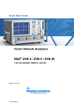
This Application Note presents means to
integrate R&S® Test and Measurement
instruments into the Agilent® ADS® Design
System.
Methods to include R&S® Instruments are
presented, accompanied by a free-ofcharge software solution which is provided
with this application note. It makes it very
easy to include R&S® Instruments into
your ADS® environment and your design
flow.
Versions for both WINDOWS XP®/
WINDOWS 7®and LINUX® operating
systems are available.
Table of Contents
Table of Contents
1MA72_9e
1
Overview ................................................................................. 4
2
Software Features / Principle of Operation.......................... 5
3
Connecting the Computer and the Instrument .................... 6
4
Installing the R&S Software .................................................. 6
4.1
Installing the R&S ADS Interface under Microsoft Windows...................6
4.2
Installing the R&S ADS Interface under Linux ..........................................7
4.3
Installing the RS ADS Design Kit................................................................8
4.4
Checking for successful installation..........................................................9
5
Operating the RSADSIF Software ....................................... 11
5.1
Registration: ...............................................................................................11
5.2
Operating.....................................................................................................12
6
Design Examples ................................................................. 15
6.1
Writing simulated data to an Arbitrary Generator...................................15
6.2
Reading IQ Data from an R&S FSx ..........................................................18
6.3
Reading S-Parameters from an ZVx with the ZVx_S2P_Model .............19
7
Model Source Instruments .................................................. 21
7.1
RS_SnP_Model ...........................................................................................21
7.2
ZVx_P2D_Model..........................................................................................23
8
Source Instruments ............................................................. 25
8.1
FSx_IQ_Source ...........................................................................................25
9
Sink Instruments ................................................................. 29
9.1
ARB_IQ_Sink ..............................................................................................29
10
ADS 2011............................................................................... 33
10.1
Changes in ADS..........................................................................................33
10.2
Changes in the RS ADS Interface .............................................................34
10.3
Update to ADS 2011 ...................................................................................34
10.4
Update Projects to ADS 2011 ....................................................................34
11
Required Licenses ............................................................... 34
®
Rohde & Schwarz Using R&S® Instruments within Agilent® ADS® Software 2
Table of Contents
1MA72_9e
12
Hardware and Software Requirements .............................. 35
12.1
PC Requirements .......................................................................................35
12.1.1
Software Requirements .............................................................................35
13
Frequently Asked Questions............................................... 36
14
Details of operation.............................................................. 39
15
Literature............................................................................... 40
16
Additional Information......................................................... 41
17
Ordering information ........................................................... 42
Rohde & Schwarz Using R&S® Instruments within Agilent® ADS® Software 3
1 Overview
1 Overview
This application note presents possibilities for including the R&S Test and
Measurement Instruments into the Agilent ADS Design System.
The Agilent ADS Design System is a powerful electronic design automation software
system. It offers complete design integration to designers of products such as cellular
phones, wireless networks, and radar or satellite communications systems. Both
analog and digital simulation can be combined, leading to a complete simulation
solution from the bit source up to the output RF power of a complete transmitter
system and also back again into the receiver for all known digital communication
standards.
By using real-world instruments in combination with such a design system, the design
flow can be much more efficient, for example
generate the baseband signal for a new digital communication standard and feed
this signals from ADS into a real-world ARB and RF signal generator to create this
signal and examine e.g. an RF amplifier
check the influence of digital filters, coding, … on the real world signal
record a real-world signal from e.g. an transmitter and check the parameters in
comparison to the original signal - also in the presence of a simulated signal with
noise, fading, …
integrate the parameters of a real-world Device Under Test (S-parameters of an
amplifier, …) into your design by using a Vector Network Analyzer for
characterization
These are only a few ideas how about integrating test equipment into your design flow.
With this application note, ways for integrating Rohde & Schwarz test equipment into
ADS will be preset. This integration will be available for both analog and digital
simulations, and signal sources as well as signal sinks can be included into your
design.
The main key features of this solution are:
One-button-solution (as easy to operate as the ADS simulator).
Components for analog and digital simulation.
Direct integration into ADS (including R&S specific palettes, menus, schematic
symbols).
Complete instrument configuration within the ADS Design Environment.
Multiple Instrument Components (1 component support all instruments for the
desired measurement task)
Automatic generation of files in well-known ADS formats (TIM, SIG, S2P, …) during
the simulation.
Support of all interfaces to the instruments (IEEE, LAN, …) for all integrated
components.
Protocol and log file generation for all operations.
1MA72_9e
Rohde & Schwarz Using R&S® Instruments within Agilent® ADS® Software 4
Software Features / Principle of Operation
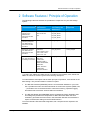
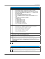
2 Software Features / Principle of Operation
The following instrument classes are provided as components for your ADS design
system:
Task
Read S parameters vs
frequency from
Measurement
Instrument into ADS
Simulation
Supported
Instruments
Component
provided by the
RS Solution
Type of Network
supported
Analog
ZVR/ZVC/ZVM
RS_S1P_Model
ZVA / ZVB / ZVT
RS_S2P_Model
ZVL
RS_S3P_Model
RS_S4P_Model
Read S parameters vs
frequency and power
from Measurement
Instrument into ADS
Simulation
ZVA / ZVB / ZVT
ZVx_P2D_Model
Analog
Read IQ vs time data
from Measurement
Instrument into ADS
Simulation
FSIQ+B70
FSx_IQ_Source
Analog & digital
ARB_IQ_Sink 1)
digital
Send IQ vs time data
from ADS Simulation to
a ARB Signal Generator
FSG / FMU36 / FSP /
FSU / FSUP / FSQ /
FSW / FSV / FSL
SMJ100A+B9/B10/B11,
SMU200A
+B9/B10/B11,
SMATE+B10/B11,
SMBV+B10/B50/B51,
SMIQ+B60,
AMIQ, AMU200A
+B9/B10/B11,
AFQ100A+B10/B11
1) As SMU, SMJ, SMATE and SMBV are fully compatible for IQ modulation, SMJ, SMATE and
SMBV are referred to as SMU in general in the following descriptions.
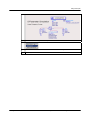
To understand the description and the basic principle of operation, some words on the
basic design. The provided solution consists of 2 parts:
1. The RS ADS Interface (RSADSIF) which is an executable installed on your local
PC. It provides the link to the RS Instruments via various bus systems (IEEE, LAN,
…) and takes care on the data transfer. Instrument scanning, operation logging
and data format conversion are done within this software.
2. The RS ADS Design Kit (RSADSDK) which is installed as Design Kit within ADS.
This Design Kit provides the components for RS instruments within the ADS
schematic, generates the menu items in the Schematic Window and realizes the
export of instruments settings to the RS ADS Interface.
To use the Rohde & Schwarz ADS Integration, both components are required to be
installed.
1MA72_9e
Rohde & Schwarz Using R&S® Instruments within Agilent® ADS® Software 5
Connecting the Computer and the Instrument
3 Connecting the Computer and the
Instrument
The following chapter describes the connection to establish between the PC and the
measurement instruments in order to connect to the instruments
Connecting the Instruments
Instruments can be connected via several bus systems:
GPIB / IEEE bus
Network Interface (TCP/IP)
USB Bus
4 Installing the R&S Software
Installing the RS ADS Interface is divided into 2 steps:
1.
2.
Installing the RS ADS Interface itself
Installing the RS ADS Design Kit for the integration into ADS
The RS ADS Interface can be installed under Microsoft Windows and LINUX.
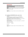
4.1 Installing the R&S ADS Interface under Microsoft
Windows
The software has to be installed on the PC. To do this, run RSADSIF_<Version
Number>.exe and follow the instructions on the screen. All necessary settings
(installation path, program folder location, …) can be set during the installation.
The software will install:
•
•
the software itself including a release history and an uninstall routine
the Design Kit files for ADS version 2009Update 1 and later versions
During installation, the program files are copied to the directory of your choice and a
new folder ("RS ADS Interface" by default) is installed in your Start – Program menu.
1MA72_9e
Rohde & Schwarz Using R&S® Instruments within Agilent® ADS® Software 6
Installing the R&S Software
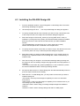
IMPORTANT NOTE
Installing the RS ADS Interface Software is only possible in folders following the 8character-rule, so spaces and long directory names are not allowed. This is due to
limitations of the ADS Design System.
If RS ADS Interface software is installed in such a directory, the interface WILL NOT
WORK!
After the installation is completed, click "RS ADS Interface" from the new program
folder entry to run the software.
Design Kit
Install the design kit according to chapter 4.3 and verify the installation according to
chapter 4.4.
4.2 Installing the R&S ADS Interface under Linux
Install files
Copy the following files into your install directory (e.g. /usr/local/RSADSIF):
RS_2006A.zip, RSADSIF.exe, libQtCore.so.4, libQtGui.so.4 and libQtScript.so.4
Create an empty folder called “log” inside your install directory.
Important: Make sure all files and directories are existent and named correctly (case
sensitive!) and don’t omit the .exe, even if not necessary under Linux.
Environment Variable
Add your program directory to the environment variable “RSADSIF” e.g. by adding the
following to your /etc/profile:
RSADSIF=/usr/local/RSADSIF/
export PATH … … … RSADSIF
Design Kit
Install the design kit according to chapter 4.3 and verify the installation according to
chapter 4.4.
1MA72_9e
Rohde & Schwarz Using R&S® Instruments within Agilent® ADS® Software 7
Installing the R&S Software
4.3 Installing the RS ADS Design Kit
1MA72_9e
1.
From the ADS Main window, choose DesignKit > Install Design Kits. The Install
ADS Design Kit dialog box appears.
2.
Click Unzip Design Kit Now… . The Unzip ADS Design Kit dialog box appears.
3.
To specify the path and file name of the file you want to unzip, click Browse next
to the Unzip File field. The Unzip From File Browse dialog box appears.
4.
Select the Design Kit ZIP file RS_2006A.zip (running ADS 2009 or lower) or
RSDK2011 (running ADS 2011) within your RS ADS Interface folder as installed
before and click OK. Select the ZIP file that matches your ADS Installation
Version.
(For ADS2008/2009, the same files as for version 2006 can be used.)
Please note that spaces are not allowed in the full path name.
5.
To specify the new location for the files you want to unzip, click Browse next to the
To Directory field. The Unzip To Directory Browse dialog box appears.
6.
Select the location you want to install the Design Kit. If your company does not
already have a specified location to store design kits, create a new directory to
install the files.
7.
Click OK to unzip your design kit. An Information Message dialog reporting that
the design kit was successfully unzipped may appear after the unzip operation is
complete.
You will find a new folder "RS_2006A" (RSDK2011 in case of ADS 2011) within
the selected installation folder containing all Design Kit files.
8.
All sections within the box "2. Define Design Kit" are filled automatically when the
previous steps are finished successfully.
9.
Within the box "3. Install Design Kit", you may select at which level you want to
install the design kit:
SITE LEVEL: Used to provide design kit capability for users in a networked
environment.
USER LEVEL: Used to provide design kit capability for an individual user so you
can manage your own design kits.
STARTUP LEVEL: Used to help you manage multiple design kits at different
locations.
PROJECT LEVEL: Used to manage design kits within an ADS project.
Rohde & Schwarz Using R&S® Instruments within Agilent® ADS® Software 8
Installing the R&S Software
For the RS ADS Interface, SITE LEVEL or USER LEVEL is recommended.
10. After selecting a level, click OK in the Install ADS Design Kit dialog to install and
enable the design kit. An Information Message dialog stating that the design kit
was successfully enabled appears. Click OK to clear the Information Message
dialog. Your design kit is now ready for use.
Details on the installation and usage of Design Kits into ADS can be found in the ADS
manual "Design Kit Installation and Setup" which can be found on the Internet [13] or
on your ADS Installation CD-ROM's or PC Installation.
Please restart ADS in order to complete the Design Kit installation.
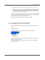
4.4 Checking for successful installation
After a successful installation and a restart of your ADS design environment, you will
find
1. New Menu Entries
The following new menu entry will appear in your ADS schematic menu:
Use "Start simulation" to start your simulation in combination with a data import and
export from the R&S instruments.
Use "Open RS ADS Interface" for configuration of the instrument connection and
interface customization.
1MA72_9e
Rohde & Schwarz Using R&S® Instruments within Agilent® ADS® Software 9
Installing the R&S Software
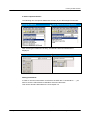
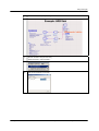
2. New Component Entries
The following new Component Parameter List entry in your RF Design Environment:
Analog/RF Network
Digital Signal Processing Network
After selecting the Parameter List entry, the Rohde & Schwarz Palette will be
displayed:
Analog/RF Network
Digital Signal Processing Network
Adding Instruments
In order to use other instruments connected to the IEEE bus / LAN interface / …, you
have to enter the VISA Resource Identifiers of these instruments.
This can be done like described in the next chapter 5.2.
1MA72_9e
Rohde & Schwarz Using R&S® Instruments within Agilent® ADS® Software 10
Operating the RSADSIF Software
5 Operating the RSADSIF Software
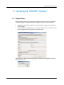
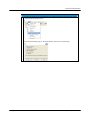
5.1 Registration:
When RSADSIF starts, the Registration form appears. Please register the installation;
it is free and does not result in any further commitments for you or your company.
If RSADSIF has not been registered, you can still start the program by clicking the
Continue button.
If you complete the Registration form, a keycode will be sent to you. Enter the code
into the Registration form and click the Continue button.
After inserting a valid keycode the registration is complete, the registration form does
not appear any more.
1MA72_9e
Rohde & Schwarz Using R&S® Instruments within Agilent® ADS® Software 11
Operating the RSADSIF Software
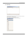
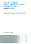
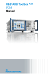
5.2 Operating
The RS ADS Interface software supports the usage of any interface to connect to the
instrument (IEEE bus, LAN interface, USB).
Use the tab Add Device to add instruments to your setup:
Choose a label, an instrument type, the protocol and the resource:
1MA72_9e
Rohde & Schwarz Using R&S® Instruments within Agilent® ADS® Software 12
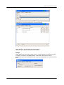
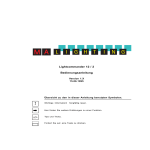
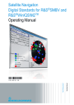
Operating the RSADSIF Software
Examples for connecting instruments via LAN and GPIB:
Using "Remove", the selected entry can be deleted.
"Rename" will change the selected resource entry.
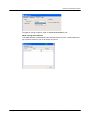
Settings:
Under Settings you can select "Close on Error", if and under what conditions a log file
is created, and "Show compatibility Mode". In the latter case you can include
instruments which are not available under "Type" but compatible to an instrument listed
there.
.
1MA72_9e
Rohde & Schwarz Using R&S® Instruments within Agilent® ADS® Software 13
Operating the RSADSIF Software
The path for saving a logfile is: Path: C:\WINNT\RS\RSADSIF\LOG
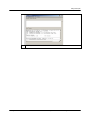
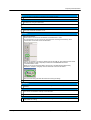
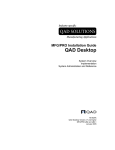
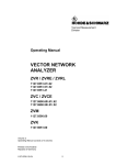
While running the simulation
If RS ADS Interface is started during the ADS Simulation process, a small window will
pop up which will inform you on all actions and errors:
1MA72_9e
Rohde & Schwarz Using R&S® Instruments within Agilent® ADS® Software 14
Design Examples
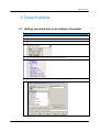
6 Design Examples
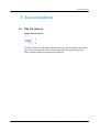
6.1 Writing simulated data to an Arbitrary Generator
Writing simulated data to an Arbitrary Generator
1MA72_9e
1)
Start your ADS design environment.
2)
Create a new project and create a new design.
3)
From the Component Palette List, choose "Rohde & Schwarz":
4)
Choose the ARB_IQ_Sink and place the model onto your layout:
5)
Configure all parameters as required by double-clicking to the ARB symbol:
Rohde & Schwarz Using R&S® Instruments within Agilent® ADS® Software 15
Design Examples
6)
7)
Close the box and complete your design:
Start the simulation using the menu entry
"Rohde & Schwarz > Start simulation":
8)
1MA72_9e
Wait until the simulation has finished:
Rohde & Schwarz Using R&S® Instruments within Agilent® ADS® Software 16
Design Examples
9)
1MA72_9e
Evaluate your simulations results.
Rohde & Schwarz Using R&S® Instruments within Agilent® ADS® Software 17
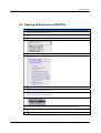
Design Examples
6.2 Reading IQ Data from an R&S®FSx
Reading IQ Data
1)
Start your ADS design environment.
2)
Create a new project and create a new design.
3)
From the Component Palette List, choose "Rohde & Schwarz":
4)
Choose the A/D component and place the model onto your layout:
5)
Configure all parameters as required by double-clicking on the component
6)
Close the box and complete your design:
7)
Start the simulation using the menu entry
"Rohde & Schwarz > Start simulation":
1MA72_9e
8)
Wait until the simulation has finished and the R&S ADS-Interface dialog box closes.
9)
Evaluate your simulations results.
Rohde & Schwarz Using R&S® Instruments within Agilent® ADS® Software 18
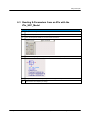
Design Examples
6.3 Reading S-Parameters from an ZVx with the
ZVx_S2P_Model
Reading S-Parameters with the S2P Model
1MA72_9e
1)
Start your ADS design environment.
2)
Create a new project and create a new design.
3)
From the Component Palette List, choose "Rohde & Schwarz":
4)
Choose the RS_S2P_Model component and place the model on your layout:
5)
Configure all parameters as required by double-clicking on the component.
6)
Close the box and complete your design:
Rohde & Schwarz Using R&S® Instruments within Agilent® ADS® Software 19
Design Examples
1MA72_9e
7)
Start the simulation using the menu entry "Rohde & Schwarz > Start simulation":
8)
Wait until the simulation has finished and the R&S ADS Interface dialog box closes.
9)
Evaluate your simulations results.
Rohde & Schwarz Using R&S® Instruments within Agilent® ADS® Software 20
Model Source Instruments
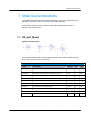
7 Model Source Instruments
This chapter describes the model source instruments. These are components which
generate a "behavior model" for a specific real-world component.
This behavior model can be a S parameter file with sweeped frequency and - if
decided - also sweep power.
7.1 RS_SnP_Model
Symbol and Description
The component will control a Vector Network Analyzer and create a S parameter file
for a 1-Port / 2-Port / 3-Port / 4-Port DUT.
Parameters
1MA72_9e
Name
Description
Default
Unit
Type
RunRFSetup
Set RF parameters: YES, NO
YES
--
bool
RunPreSim
Measurement is done before the simulation: YES, NO
YES
--
bool
RunPostSim
Measurement is done after the simulation: YES, NO
NO
--
bool
RunPreset
Preset the instrument: YES, NO
YES
--
bool
Label
Instrument’s label
“ZVx1”
--
string
FreqStart
Starting frequency for frequency sweep
10 MHz
Hz
real
FreqStop
Stop frequency for frequency sweep
1 GHz
Hz
real
FreqStep
Frequency steps for frequency sweep 1)
10 MHz
Hz
real
RFLevel
RF Output Level
0
dBm
real
IFFilter
IF filter bandwidth
10
kHz
real
Rohde & Schwarz Using R&S® Instruments within Agilent® ADS® Software 21
Model Source Instruments
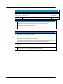
Pins and Files
Name
Description
Signal Type
Pin "REF"
Reference Port
S parameter
Pin "P1"…"P4"
Ports of the DUT
S parameter
File Format
SnP file format
---
Footnotes
1)
The sweep direction is taken from LevelStart and LevelStop, the sign of LevelStep is ignored and will
be assigned to match the sweep direction derived from LevelStart and LevelStop.
The resulting maximum number of sweep points for the ZVR / ZVC is limited to 2001 for 1-port
measurement and 501 for 2-port measurement.
Notes
1)
RunPreSim and RunPostSim determine if the communication with the instrument shall be done
before and/or after the simulation of the circuit.
If you do not want the simulator to control the component, select NO for both values.
2)
If RunPreset is selected, the instrument will be reset and all channel assignments will be executed
before other settings are performed on the instrument.
If RunPreset is not selected, the necessary channels are queried automatically from the instrument.
S parameters distributed on several channels can not be used for this measurement.
1MA72_9e
3)
If RunRFSetup or RunPreset is selected, the settings for FreqStart, FreqStop, and FreqStep will be
executed.
4)
The data from the instrument are always stored as S1P / S2P / S3P / S4P files with the name
"RS_SxP.sxp" (x=1..4) in the "\data" directory of the current project.
Rohde & Schwarz Using R&S® Instruments within Agilent® ADS® Software 22
Model Source Instruments
7.2 ZVx_P2D_Model
Symbol and Description
The component will control a Vector Network Analyzer and create an S parameter file
for a 2-Port DUT. Additionally, the power at the ports will be sweeped according to the
settings.
Parameters
Name
Description
Default
Unit
Type
RunRFSetup
Set RF parameters: YES, NO
YES
--
bool
RunPreSim
Measurement is done before the simulation: YES, NO
YES
--
bool
RunPostSim
Measurement is done after the simulation: YES, NO
NO
--
bool
RunPreset
Preset the instrument: YES, NO
YES
--
bool
Label
Instrument’s label
“ZVx1”
--
strimg
FreqStart
Starting frequency for frequency sweep
10 MHz
Hz
real
FreqStop
Stop frequency for frequency sweep
1 GHz
Hz
real
FreqStep
Frequency steps for frequency sweep 1)
10 MHz
Hz
real
LevelStart
Starting level for level sweep
-30 dBm
dBm
real
LevelStop
Stop level for level sweep
-10 dBm
dBm
real
LevelStep
Level steps for level sweep 1)
1 dB
dB
real
Pins and Files
1MA72_9e
Name
Description
Signal Type
Pin "IN"
Port 1 of the DUT
S parameter
Pin "OUT"
Port 2 of the DUT
S parameter
File Formats
S2D file format
---
Rohde & Schwarz Using R&S® Instruments within Agilent® ADS® Software 23
Model Source Instruments
Notes
1)
RunPreSim and RunPostSim determine if the communication with the instrument shall be done
before and/or after the simulation of the circuit.
If you do not want the simulator to control the component, select NO for both values.
2)
If RunPreset is selected, the instrument will be reset and all channel assignments, … will be
executed before other settings are performed on the instrument.
If RunPreset is not selected, the necessary channels are queried automatically from the instrument.
S parameters distributed on several channels can not be used for this measurement.
3)
If RunRFSetup or RunPreset is selected, the settings for FreqStart, FreqStop, and FreqStep will be
executed.
4)
The data from the instrument are always stored as P2D files with the name "ZVx_P2D.p2d" in the
"\data" directory of the current project.
Required Licences:
This component requires the license "Design Environment" (ads_schematic) for
placing the component and "RF Systems Models" (mdl_systemlib) for simulation.
1MA72_9e
Rohde & Schwarz Using R&S® Instruments within Agilent® ADS® Software 24
Source Instruments
8 Source Instruments
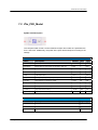
8.1 FSx_IQ_Source
Symbol and Description
The FSx_IQ_Source model downloads data from any of the R&S FSIQ / FSP / FSUP /
FSU / FSQ / FSG / FMU36 / FSW / FSV/FSL Spectrum and Signal Analyzers into
ADS. It outputs IQ data as recorded from the detector.
1MA72_9e
Rohde & Schwarz Using R&S® Instruments within Agilent® ADS® Software 25
Source Instruments
Parameters
Name
Description
Default
Unit
Type
RunRFSetup
RF parameters shall be set: YES, NO
YES
--
bool
RunPreSim
Sampling is done before the simulation: YES, NO
YES
--
bool
RunPostSim
Sampling is done after the simulation: YES, NO
NO
--
bool
RunPreset
Instrument is presented: YES, NO
YES
--
bool
LocalFileName
Name of the copy of the IQ data file (extension-free) 1)
'IQ_In'
--
string
LocalFileType
Type for file format to store on disc: none, TIM, SIG
SIG
--
enum
RFFrequency
RF Frequency
1 GHz
Hz
real
RFLevel
RF Level
-30 dBm
dBm
real
RFRefOscSource
Source for 10 MHz reference frequency: INT, EXT
INT
--
enum
IQINSampleClock
Input sampling rate for Digital Baseband Input 8)
1 MHz
Hz
real
IQSampleClock
Sampling rate for the data acquisition 2)
1 MHz
Hz
real
IQSampleLength
Number of IQ samples to record 3)
1024
--
int
IQPreTrigSamples
Number of measurement values to be recorded before the
trigger point
0
1
int
IQFilter
Analog filters bandwidth in front of the A/D converter: 300
kHz, 1 MHz, 3 MHz, 10 MHz, 20 MHz, 50 MHz 4)
3 MHz
--
enum
IQAvgOn
Averaging for IQ data: ON, OFF 5)
OFF
--
bool
IQAvgCount
Average count for IQ capture 5)
1
1
int
IQSource
Source for the IQ data: RF, BB, DIQ 6)
RF
--
enum
IQBBDither
Baseband Dithering: ON, OFF 6)
OFF
--
bool
IQBBLowPass
Baseband 36 MHz lowpass filter activated: ON, OFF 6)
OFF
--
bool
IQBBBalanced
Baseband IQ mode balanced: YES, NO 6)
NO
--
bool
IQBBImp
Baseband Impedance of the IQ inputs: 50
50
--
enum
DIQRANGE
Voltage of a digital full scale value 8)
2V
V
real
TriggerMode
Mode for triggering: IMM, EXT, IFP, RFP 7)
IMM
--
enum
TriggerLevel
Level for IFP and RFP trigger
-30 dBm
dBm
real
, high 6)
Pins and Files
1MA72_9e
Name
Description
Signal Type
Pin "I"
I data from the data acquisition
Scalar Floating Point
Pin "Q"
I data from the data acquisition
Scalar Floating Point
Rohde & Schwarz Using R&S® Instruments within Agilent® ADS® Software 26
Source Instruments
Footnotes
1)
If no filename is entered, no copy is generated on the local PC
2)
The sampling rate can be set
for FSQ / FMU36 / FSG in the range of 10 kHz to 81.6 MHz in 0.1 Hz steps
for FSQ with option FSQ-B72 in the range of 20.4 MHz to 326.4 MHz in 0.1 Hz steps
for FSU / FSUP / FSP to discrete values: 32 MHz / 2n, n = 0 .. 11, resulting in a range
of 15.625 kHz to 32 MHz
For FSV in the range of 100 Hz to 45 MHz in 0.1 Hz steps
For FSV with R&S®FSV-B70 option in the range of 100 Hz to 128 MHz in in 0.1 Hz
steps
For the FSW in the range of 100 Hz to 200 MHz*)
*) standard 12.5 MHz
with R&S®FSW-B28 option 35 MHz
with R&S®FSW-B40 option 50 MHz
with R&S®FSW-B80 option 100 MHz
with R&S®FSW-B160 option 200 MHz
3)
4)
For FSL in the range of 10 kHz to 65.8 MHz
The number of samples can be set
for FSQ / FSU / FSUP / FMU36 / FSG continuous in a range of 1 to 16.776.704
for FSP without option FSP-B70 in a range of 1 to 130.560
for FSP with option FSP-B70 in a range of 1 to 523.776
for FSV continuously in a range of 1 to 20.000.000
for FSL continuously in a range of 1 to 512.000
for the FSW max. 400 Msample I and Q
20 MHz and 50 MHz filters are available with FSQ only.
For FSV/FSW the setting of the IQFilter bandwidth is omitted.
5)
Only available for FSU and 32 MHz sampling rate and IQPreTriggerSamples >= 0.
6)
Analog Baseband input only available with FSQ with option FSQ-B71 and FMU36.
Digital Baseband Input only available with FSQ or FSG with R&S FSQ-B17 Digital Baseband
Interface or FSV with FSV-B17 Digital Baseband Interface or FSW with FSW-B17.
See also Application Note 1MA147 " Using the R&SExIQ Box with FSQ and Agilent ADS Software"
where applicable.
7)
RFP for FSP with option FSP-B6.
8)
Only valid if IQSource is set to DIQ. For IQSource=RF or BB no effect.
Notes
1MA72_9e
1)
RunPreSim and RunPostSim determine if the communication with the instrument shall be done
before and/or after the simulation of the circuit.
If you do not want the simulator to control the component, select NO for both values.
2)
If RunPreset is selected, the command "SYST:PRES" (equivalent to pressing the PRESET key at
the front panel) will be executed before other settings are performed on the instrument.
Rohde & Schwarz Using R&S® Instruments within Agilent® ADS® Software 27
Source Instruments
3)
If RunRFSetup is selected, the settings for RFFrequency, RFLevel, RFRefOscSource and RFOn will
be executed.
4)
The data from the instrument are always stored as SIG files with the name "FSx_IQ_IN_I.SIG" and
"FSx_IQ_IN_Q.SIG" in the "\data" directory of the current project.
If you want additional copies of the file in the SIG or TIM format, you can specify LocalFileName and
LocalFileType for name and type.
The complete filenames will be <LocalFileName>_[I/Q].[SIG/TIM].
5)
IQSampleClock and IQSampleLength must be entered according to the valid value range as
described in the table above.
6)
IQPreTriggerSamples specified the number of samples between the trigger event and the start of the
IQ data recording itself.
7)
If IQScaleMode is set to VOLT, IQ input samples are assumed to be voltage values. An overrange of
the values will result in an error.
If MAX is selected, IQ input samples will be scaled to fit the value range of the D/A converter with
maximum dynamic range.
8)
IQAvgOn and IQAvgCount switches the averaging of IQ samples within the FSU on or off.
If averaging is selected, IQ data are averaged inside the instrument with phase synchronized
sampling according to the external trigger.
9)
If an FSQ with option FSQ-B71 is used, IQSource can be switched between RF and Baseband (BB)
source. For baseband inputs, additional options (IQBBDither , IQBBLowPass , IQBBBalanced and
IQBBImp) are available.
10)
The TriggerMode can be switched between Immediate (IMM), External (EXT - Trigger provided by
the backpanel BNC connector), IF Power (IFP - Standard Bandwidth Detector) and RF Power (RFP Bandwidth Extended Detector for FSP).
Use TriggerLevel to set the level for IF and RF Power Trigger level.
Required Licenses
This component requires the license "Design Environment" (ads_schematic) for
placing the component and "Ptolemy Simulator" (sim_systime) for simulation.
1MA72_9e
Rohde & Schwarz Using R&S® Instruments within Agilent® ADS® Software 28
Sink Instruments
9 Sink Instruments
9.1 ARB_IQ_Sink
Symbol and Description
The ARB_IQ_Sink model downloads time domain IQ data from ADS to the R&S Vector
Signal Generator or Arbitrary Waveform Generator or R&S I/Q Modulation Generator.
The simulated IQ data are stored from ADS to the local PC disc and then automatically
transferred to the ARB generator by calling the RS ADS Interface.
The files which are downloaded to the ARB are called "ARB_IQ_Sink_I.SIG" and
"ARB_IQ_Sink_Q.SIG" and are stored in the "\data" directory of your simulation.
Note: Please make sure that your ADS design delivers an equal number of I and Q
data by adjusting the START and STOP parameters of the simulation (e.g. DefaultTimeStart/Stop and DefaultNumericStart/Stop). If the number is not equal a warning is
displayed in the R&S simulation window and the smaller number is used.
1MA72_9e
Rohde & Schwarz Using R&S® Instruments within Agilent® ADS® Software 29
Sink Instruments
Parameters
Name
Description
1)
Default
Unit
Type
YES
--
bool
RunRFSetup
Set RF parameters: YES, NO
RunPreSim
Waveform upload is done before the simulation:
YES, NO
NO
--
bool
RunPostSim
Waveform upload is done after the simulation: YES,
NO
YES
--
bool
RunPreset
Preset the instrument: YES, NO 2)
--
bool
LocalFileName
Name of the copy of the IQ data file (extension-free)
''
--
string
3)
1MA72_9e
LocalFileType
Type for file Pin "Q"on disc: TIM, SIG, WV
SIG
--
enum
RFFrequency
RF Frequency 4)
1 GHz
Hz
real
-30 dBm
dBm
real
4)
RFLevel
RF Level
RFRefOscSource
Source for the 10 MHz reference frequency: INT,
EXT
INT
--
enum
RFOn
Determine if RF is switched on after IQ data
download; YES, NO 5)
YES
--
bool
ARBSampleClock
Clock rate of the D/A converter 6)
1MHz
Hz
real
ARBClockSource
Source of the ARB clock: INT, EXT
INT
--
enum
ARBFileName
Name of the file to be generated on the ARB
'ADS_IN
'
--
string
ARBComment
Comment for the ARB file
''
--
string
ARBOn
Switch ARB on after IQ download: YES, NO
YES
--
bool
ARBTrigger
Trigger mode of the ARB: AUTO, RETR
AUTO
--
enum
AUTO
--
enum
7)
IQBBGain
Baseband Gain: AUTO, -3dB, 0dB, 3dB, 6dB
IQWideBand
IQ Wideband Mode: ON, OFF 7)
OFF
--
bool
Marker1On
Time Marker 1 is on [samples]
10
--
string
Marker2On
Time Marker 2 is on [samples]
10
--
string
IQBBOutputBal
Differential outputs: YES, NO 8)
NO
--
bool
14
--
int
9)
IQDigBitWidth
Digital output bit width: 1 … 16
IQDigBitAlignment
Digital output bit alignment: LSB lowest, MSB
highest 9)
LSB
lowest
--
enum
IQDigBitUnused
Digital output unused bits state: LOW, HIGH 9)
LOW
--
enum
Rohde & Schwarz Using R&S® Instruments within Agilent® ADS® Software 30
Sink Instruments
Pins and Files
Name
Description
Signal Type
Pin "I"
I input waveform data
Scalar Timed
Pin "Q"
Q input waveform data
Scalar Timed
Footnotes
1MA72_9e
1)
If RunRFSetup is selected, the settings for RFFrequency, RFLevel, RFRefOscSource and RFOn will
be executed. Not supported for AMIQ, AMU or AFQ.
2)
If RunPreset is selected, the command "SYST:PRES" (equivalent to pressing the PRESET key at
the frontpanel) will be executed before other settings are performed on the instrument
3)
If no filename is entered, no copy is generated on the local PC and the file is only downloaded to the
ARB.
4)
Not supported for AMIQ, AMU or AFQ
5)
Not supported for AMIQ, AMU or AFQ.
6)
The clock rate can be set in a range of
400 Hz to 100 MHz
for SMU/AMU/SMJ + B9/B10/11
1 kHz to 40 MHz
for SMIQ + B60
10 Hz to 100 MHz
for AMIQ
400 Hz to 150 MHz
SMBV
1 kHz to 300 MHz
AFQ100A
1kHz to 600 MHz
AFQ100B
7)
Only available for SMU/SMJ100A.
8)
Only available for AMIQ-B2 / SMU-B16 / SMJ-B16 / AFQ100A / AMU200A / AFQ.
9)
Only available for AMIQ-B2 / AFQ100A / AMU-B18.
Rohde & Schwarz Using R&S® Instruments within Agilent® ADS® Software 31
Sink Instruments
Notes
1MA72_9e
1)
RunPreSim and RunPostSim determine if the communication with the instrument shall be done before
and/or after the simulation of the circuit.
If you do not the simulator to control the component, select NO for both values.
2)
The data from the simulation are always stored as SIG files with the name "ARB_IQ_Sink_I.SIG" and
"ARB_IQ_Sink_Q.SIG" in the "\data" directory of the current project.
If you want additional copies of the file in the SIG or TIM format, you can specify LocalFileName and
LocalFileType for name and type.
The complete filenames will be <LocalFileName>_[I/Q].[SIG/TIM].
3)
If ARBSampleClock is set to 0, the Samples Clock is derived from the timing of the simulation.
Otherwise, the entered value will be used.
At least 1 component in the design must specify the timing.
4)
If ARBOn is selected, the ARB will be reset, the file generated (name ARBFileName) by the
simulation will be loaded and started.
5)
Marker1On and Marker2On specify the number of samples the marker will stay on (TTL High). The
marker will then turn off (TTL Low) until the end of the waveform is reached.
If you want to realize e.g. a Marker Pulse with ON/OFF Ratio of 1/1, please set the value to ½ of the
total samples number.
6)
Data are always written in the non-volatile memory of the instrument.
Rohde & Schwarz Using R&S® Instruments within Agilent® ADS® Software 32
ADS 2011
10 ADS 2011
With ADS 2011 there have been many changes regarding legacy Design Kit support.
As a result, ADS 2011 is no longer compatible with with Design Kits from previous
versions and vice versa. To use ADS2011 with the RS ADS Interface you need the
latest Version (2.3 or later).
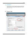
10.1 Changes in ADS
Changes
1MA72_9e
1)
Unified palette (only one palette regardless of simulation mode
2)
All dropdown options have been replaced with a text entry. All valid options (numbers) are noted in
the option description.Table text, see example below.
Rohde & Schwarz Using R&S® Instruments within Agilent® ADS® Software 33
Required Licenses
10.2 Changes in the RS ADS Interface
You need the latest version of the ADS Interface (version 2.3 or later) to work with ADS
2011. You need to install the RSDK2011 Design Kit.
10.3 Update to ADS 2011
Update Procedure
1)
Install ADS 2011
2)
Install Rohde & Schwarz ADS Interface (for ADS 2011)
10.4 Update Projects to ADS 2011
Project Update
1)
Open your project in your old ADS version and note all RS Component settings
2)
Convert your project to an ADS 2011 workspace
3)
Open your project and delete all RS Components
4)
Place your RS Components from the new palette again
5)
Reconfigure your components
6)
Run your simulation as in previous versions
11 Required Licenses
This component requires the license "Design Environment" (ads_schematic) for
placing the component and "Ptolemy Simulator" (sim_systime) for simulation.
1MA72_9e
Rohde & Schwarz Using R&S® Instruments within Agilent® ADS® Software 34
12 Hardware and Software Requirements
12.1 PC Requirements
Recommended system configuration for the provided R&S software:
Operating system:
Windows XP or Windos 7
Microsoft Internet Explorer 5.0 or higher
Or:
LINUX REDHAT
Generic PC requirements:
Pentium II 450 MHz or higher
1024 MByte
100 MByte free hard disc space
XGA monitor (1024x768)
plus space for storing data files
IEC/IEEE bus interface
(for instrument control over IEEE Bus)
LAN interface
(for instrument control over LAN interface)
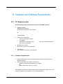
12.1.1 Software Requirements
Agilent ADS 2009A or above including simulators which are required for the
decided simulation
VISA (Virtual Instrument Software Architecture)
National Instruments VISA Version 4.6 or above
OR:
Agilent VISA Version M.01.01 or above
For detailed information on system requirements of Agilent ADS, please refer to the
manual "Installation on PC Systems" of your ADS installation.
1MA72_9e
Rohde & Schwarz Using R&S® Instruments within Agilent® ADS® Software 35
Frequently Asked Questions
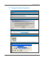
13 Frequently Asked Questions
Question
The "Rohde & Schwarz" menu bar does not work (I can not start the simulation or open the RS
Interface)
Answer
After the installation, ADS may need to be restarted in order to read in the Environmental Variable
that tells ADS where to find the RS ADS Interface.
Please restart ADS. This might be necessary 2 times.
Question
After installing and starting the RS ADS interface, the message
pops up.
Answer
Please install the VISA interface by downloading and installing the latest version using either
(http://www.ni.com/visa) or
(http://www.agilent.com > search for "VISA")
National Instruments VISA
Agilent VISA
Question
When I press the Simulation button
the simulation starts, but stops due to errors, and the instruments are not controlled by the PC
Answer
Please use the menu entry "Rohde & Schwarz > Start simulation"
in order to start the simulation with R&S instrument integration.
1MA72_9e
Rohde & Schwarz Using R&S® Instruments within Agilent® ADS® Software 36
Frequently Asked Questions
Question
I can not find my instrument connected via the network interface.
Answer
Please start the RS ADS Interface, use the VISA Resource Editor and add a Network instrument
connection by using the "Add" button.
Question
When I start my digital simulation with the ARB sink, the error message: "There are no sources or
sinks that control the simulation" occurs.
Answer
The ARB_IQ_Sink component is set to "ControlSimulation = NO" by default. It will collect as many
data as are available.
Please insert a source that has the attribute "ControlSimulation = YES".
As a workaround (if you do not have any other elements controlling the simulation), add a
"NumericSink" control that controls the simulation:
If this is not possible in your design, please push into the ARB_IQ_Sink (select the button below
and click the ARB_IQ_Sink component) and set both TimedDataWrite elements to
"ControlSimulation = YES".
Details on the Control of the Simulation can be found in the ADS Manual "ADS Ptolemy
Simulation", Chapter 3, Paragraph "Sources and Sinks Control the Simulation".
Note that these settings will NOT be stored when leaving the design.
Question
When I run a simulation based on an S4P model I get the error “Not all S-parameters on one
channel”.
Answer
Please make sure that all S-Parameters that are to be measured are on one channel. An easy way
is to use the “All S-Params” soft key on the instrument.
Question
When I open a design containing R&S instruments, I get error messages and the symbols of the
instruments are missing
1MA72_9e
Rohde & Schwarz Using R&S® Instruments within Agilent® ADS® Software 37
Frequently Asked Questions
Answer
You have only support for an activated design type. Please change this in the menue entry “Tools > Advanced Design System Setup…”
Set the supported design types to: “Both, With Default:” and choose your default type.
1MA72_9e
Rohde & Schwarz Using R&S® Instruments within Agilent® ADS® Software 38
Details of operation
14 Details of operation
Interoperation concept
When the simulation is started via ADS using the special "Rohde & Schwarz >>
Start simulation" menu entry, the following steps are executed:
1)
The current schematic is scanned for R&S components (this does not include hierarchical schematic
components in lower layers).
2)
For each R&S component, all parameters are dumped to a file "RSADSIF.INI" in the base directory
of the current project.
3)
The external tool "RSADSIF.EXE" is called with the parameters
to pass the project directory
- /PRE_RUN
to indicate a pre-simulation run
4)
RSADSIF will establish the connection to the instruments, do all the configuration work, perform all
measurements and store all acquired data in the "/data" directory of the current project.
5)
The simulator will start and run the simulation
6)
The external tool "RSADSIF.EXE" is called with the parameters
7)
1MA72_9e
- /PROPATH=<Project Path>
- /PROPATH=<Project Path>
to pass the project directory
- /POST_RUN
to indicate a post-simulation run
RSADSIF will establish the connection to the instruments, do all the configuration work and load all
simulated data from the "/data" directory of the current project to the instruments.
Rohde & Schwarz Using R&S® Instruments within Agilent® ADS® Software 39
Literature
15 Literature
[1]
[2]
[3]
[4]
[5]
[6]
[7]
[8]
[9]
[10]
[11]
[12]
[13]
[14]
[15]
[16]
[17]
[18]
1MA72_9e
Operating Manual Vector Network Analyzer R&S ZVA / ZVB
Operating Manual Signal Analyzer R&S FSQ
Operating Manual Spectrum Analyzer R&S FSU
Operating Manual Spectrum Analyzer R&S FSP
Operating Manual Spectrum Analyzer R&S FSV
Operating Manual Vector Signal Generator R&S SMU
Operating Manual Vector Signal Generator R&S SMBV
Operating Manual IQ Modulation Generator R&S AMU
Operating Manual R&S AFQ100A
Operating Manual R&S AFQ100B
Application Note 1MA147 "Using the ExIQ Box with FSQ and Agilent ADS
Software"
NI-VISATM User Manual, National Instruments
Available for free download:
http://www.ni.com/visa
Agilent IO Library Suite - Agilent VISA User's Guide
will be installed if you install Agilent VISA on your PC (see subfolder
"Documentation" and "Help" in the corresponding Start Menu folder)
Using Instruments, Agilent Technologies (part of the ADS documentation)
Available for free download:
http://www.agilent.com/find/eesof-docs
Understanding file formats, Agilent Technologies (part of the ADS Ptolemy
documentation)
Available for free download:
http://www.agilent.com/find/eesof-docs
Working with data files, Agilent Technologies (part of the ADS Circuit
Simulation documentation)
Available for free download:
http://www.agilent.com/find/eesof-docs
Design Kit Installation and Setup, Agilent Technologies (part of the ADS
documentation)
Available for free download:
http://www.agilent.com/find/eesof-docs
Operating Manual Spectrum Analyzer R&S FSV
Rohde & Schwarz Using R&S® Instruments within Agilent® ADS® Software 40
Additional Information
16 Additional Information
After installation, the latest program information can be found in the file Changes.txt in
the installation directory. You can access this file also from link Programs/ RS ADS
Interface/History from your Start Programs folder.
For general information about using the supported R&S instruments and its features,
please see the corresponding Operating Manuals.
Please contact [email protected] for comments and further
suggestions.
1MA72_9e
Rohde & Schwarz Using R&S® Instruments within Agilent® ADS® Software 41
Ordering information
17 Ordering information
Vector Signal Generator*) and I/Q Modulation Generator*) / Modulation
Source Options
R&S AFQ100A
IQ Modulation Generator
1401.3003.02
R&S AFQ100B
UWB Signal and I/Q Modulation Generator
1410.9000.02
R&S AMU200A
Basic Instrument
1402.4090.02
R&S AMU200A -B9
Max. 128 Msamples I and Q, Dig. Modulation
1402.8809.02
R&S SMU200A
Basic Instrument
1141.2005.02
up to 100 kHz ... 6 GHz for 1st path
---
R&S SMU-B13
Baseband Main Module
1141.8003.02
R&S SMU-B11
Max. 16 Msamples I and Q, Dig. Modulation
1159.8411.02
R&S SMJ100A
Basic Instrument
1403.4507.02
up to 100 kHz ... 6 GHz
---
R&S SMJ-B13
Baseband Main Module
1403.9109.02
R&S SMJ-B11
Max. 16 Msamples I and Q, Dig. Modulation
1403.9009.02
R&S SMBV
Base Unit
1407.6004.02
R&S SMBV-B103
9 kHz to 3.2 GHz
1407.9603.02
R&S SMBV-B51
Baseband Generator with ARB (32 Msample), 60
MHz RF bandwidth
1407.9003.02
additional RF options
additional RF options
1MA72_9e
Rohde & Schwarz Using R&S® Instruments within Agilent® ADS® Software 42
Ordering information
Signal Analyzer*), Spectrum Analyzer*) and Options
R&S FMU36
36 MHz I/Q bandwidth, 16 to 705 Msample I/Q
1303.3500.02
R&S FSG8
9 kHz to 8 GHz
1303.0002.08
R&S FSQ3
20 Hz ... 3.6 GHz
1155.5001.03
R&S FSQ-B71
Analog Baseband inputs
1157.0113.02
R&S FSQ-B17
Digital Baseband Interface
1163.0063.02
R&S FSU3
20 Hz ... 3.6 GHz
1166.1660.03
R&S FSUP8
9 kHz ... 8 GHz
1166.3505.08
R&S FSP3
9 kHz ... 3 GHz
1093.4495.03
R&S FSV3
9 kHz to 3.6 GHz
1307.9002.03
R&S FSV-B17
Digital Baseband Interface
1310.9568.02
R&S FSL3
9 kHz to 3 GHz
1300.2502.03
Network Analyzers*)
R&S ZVA8
2-port Vector Network Analyzer 300 KHz ... 8 GHz
1145.1110.08
R&S ZVA8
4-port Vector Network Analyzer 300 KHz ... 8 GHz
1145.1110.10
R&S ZVB4
2-port Vector Network Analyzer 300 KHz ... 4 GHz
1145.1010.04
R&S ZVB4
4-port Vector Network Analyzer 300 KHz ... 4 GHz
1145.1010.06
R&S ZVT8
Multiport Vector Network Analyzer 300 kHz... 8
GHz
1300.0000.08
R&S ZVL3
Vector Network Analyzer, 3 GHz, 2 ports
1303.6509.03
*) The use of other models is also possible. Only the instrument’s minimum
configuration for this application is stated. Please ask your local representative for a
configuration suiting your needs.
1MA72_9e
Rohde & Schwarz Using R&S® Instruments within Agilent® ADS® Software 43
About Rohde & Schwarz
Rohde & Schwarz is an independent group of
companies specializing in electronics. It is a leading
supplier of solutions in the fields of test and
measurement, broadcasting, radiomonitoring and
radiolocation, as well as secure communications.
Established more than 75 years ago, Rohde &
Schwarz has a global presence and a dedicated
service network in over 70 countries. Company
headquarters are in Munich, Germany.
Environmental commitment
Energy-efficient products
Continuous improvement in environmental
sustainability
ISO 14001-certified environmental
management system
Regional contact
Europe, Africa, Middle East
+49 89 4129 12345
[email protected]
North America
1-888-TEST-RSA (1-888-837-8772)
[email protected]
Latin America
+1-410-910-7988
[email protected]
Asia/Pacific
+65 65 13 04 88
[email protected]
China
+86-800-810-8228 /+86-400-650-5896
[email protected]
This application note and the supplied
programs may only be used subject to the
conditions of use set forth in the download area of
the Rohde & Schwarz website.
R&S® is a registered trademark of Rohde & Schwarz GmbH &
Co. KG; Trade names are trademarks of the owners.
Rohde & Schwarz GmbH & Co. KG
Mühldorfstraße 15 | D - 81671 München
Phone + 49 89 4129 - 0 | Fax + 49 89 4129 – 13777
www.rohde-schwarz.com