1
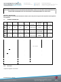
INSTALLATION, SERVICING and OPERATING INSTRUCTIONS for Synergy 900 Grill IMSG900 Revision 1 210313 Index Installation & Servicing Instructions Description Page Number / Section General Information Page 3 Installation Page 4 to 6—Section One Assembly & Commissioning Page 7 to 9—Section Two Servicing , Conversion & Cleaning Page 9 to 12—Section Three Wiring Schematic Page 13—Appendix One Spare Parts List Page 14—Appendix Two Operating Instructions Description Page Number / Section Safety Instructions Page 15—Section One Operating the Synergy Grill Page 16—Section Two Using the Synergy Grill Page 17—Section Three Cooking using the Synergy Grill Page 17 to 18—Section Four Adjusting the Height of the Grill Bars Page 19—Section Five Cleaning Page 19—20 Section Six Diagram of Removable Parts to Assist Cleaning Page 20—Section Seven Working with your Synergy Grill Page 21 IMSG900 Revision 1 210313 INSTALLATION and SERVICING INSTRUCTIONS This appliance must be installed and serviced by a competent person as stipulated by the Gas Safety (Installation & Use) Regulations. Consult these instructions before installing and using this appliance. IMPORTANT The Installer must ensure that the installation of this appliance is in conformity with these instructions and National Regulations in force at the time of installation. Particular attention must be paid to: Gas Safety (Installation & Use) Regulations Health & Safety Law – HSE Local & National Building Regulations Fire Precautions Act This appliance is CE marked on the basis of compliance with the Gas Appliance Directive for the Countries, Gas Types and Pressures as stated on the Data Plate. WARNING – THIS APPLIANCE MUST BE EARTHED It is most important that these instructions be consulted before installation and commissioning of this Grill. Failure to follow the installation guidance here-in may invalidate any warranties. These instructions are only valid for units where the Data Plate states either of the following Country Codes: GB, IE. (United Kingdom & Eire) If any other country is specified on the Data Plate then these instructions should not be used and the manufacturer should be contacted. Following a demonstration of the usage and cleaning of this Grill, all documents should be handed over to the User on completion of the installation for any future reference. Maintenance Contract A full preventative Maintenance Service Contract is available with this Grill and it is highly recommended by the Manufacturer that this facility be taken up by the User. This will ensure that optimum performance of the Grill is always achieved and any down-time is minimised by poor care and maintenance. IMSG900 Revision 1 210313 THIS APPLIANCE IS NOT INTENDED FOR USE BY PERSONS OF REDUCED PHYSICAL, MENTAL OR SENSORY CAPABILITIES (INCLUDING CHILDREN) OR LACK OF EXPERIENCE AND KNOWLEDGE, UNLESS THEY HAVE BEEN GIVEN SUPERVISION OR INSTRUCTION CONCERNING USE OF THE APPLIANCE BY A PERSON RESPONSIBLE FOR THEIR SAFETY. SECTION 1 – INSTALLATION Before installation—check the local distribution condition, nature and pressure of gas and the adjustment of this appliance are compatible. 1.1 TECHNICAL INFORMATION Model Width (mm) Depth (mm) Height (mm) Weight (kg) Gas Inlet Gas Inlet Pressure Injector size Flue Type Nat Gas 900 640 340 115kg 3/4" BSP (female) 20mbar 2.2 mm A3 LPG Cat 3+ 900 640 340 115kg 3/4" BSP (female) G30 = 28-30mbar G31 = 37mbar 1.5 mm A3 LPG Cat 3B/P 900 640 340 115kg 3/4” BSP (female) G30/G31 = 30mbar 1.5mm A3 Cat 2H (20) 3+ (28-30/37) 3B/P (30) G 20 G 30 and G 31 G 30/G 31 Supply Pressure P 20mbar G 30 = 28-30mbar G 31 = 37mbar 30mbar Total Nominal NET heat Input ΣQn 11.4 kW 12.6 kW 1.206 m³/h 0.994 kg/h 5.7 kW 6.3 kW Nominal Rate / burner 0.603 m³/h 0.497 kg/h Burner setting pressure 15.0mbar N/A* 2 2 2.2 1.5 Gas Type(s) Total nominal rate Nominal NET heat Input/burner Qn No of burners Injector size (mm) per burner Electrical supply 1.12 Data Table * Appliance regulator out of action IMSG900 Revision 1 210313 230V ~ 50Hz<1KW 1.2 UNPACKING This unit is heavy—Do not attempt to lift with less than three people The unit will normally be delivered on its own pallet. Place the pallet in a clear space as close to the install area as possible. Carefully remove all packaging and retain all documentation. The warranty registration should be completed and sent back to the manufacturer to ensure warranty cover. Remove the top and cast iron bars, (six in total with the 900 model) and place to one side; this will lighten the unit as much as possible. With the required amount of people carefully lift the unit on to its stand. (Stand units are available from your supplier). Replace the cast iron cooking grids and top. 1.3 SITING The grill may be mounted on any of the following options: Bench Single or Multiple Units Available from your supplier Because of its design and unlike other grills, your Synergy Grill does not require a minimum safety clearance around the unit. It is recommended that there should be sufficient clearance all around the grill from any combustible wall or object liable to damage when overheated. It is also advised that a minimum of 100mm clearance should be allowed to facilitate access to the gas connector at rear. Ensure that the power lead is not stretched or strained when plugging into the electrical supply and is not causing any obstruction. There must be a minimum vertical clearance of 900mm above the cooking area to ensure no overheating of overlaying combustible surfaces. The front panel of your Synergy Grill should be kept clear of any obstructions to allow maintenance of the unit. Note Upper sections of the unit are designed to stay relatively cool when compared to other types of grill, however, as a precaution the unit should be positioned in a manner which minimises the risk of accidental touching. 1.4 VENTILATION The grill MUST be installed level in a well lit and draught free position. Adequate ventilation, whether natural or mechanical, must be provided to ensure sufficient air for combustion and removal of combustion products, which may be harmful to health. Recommendations for Ventilation of Catering Appliances are given in BS5440:2. For multiple unit installations, requirements for individual appliances should be added together. Installation should be made in accordance with local and/or national regulations applying at the time. Positioning the grill below a ventilated canopy is the most suitable arrangement. Warning Remember, dirty extraction filters become combustible, hence the importance of adhering to the stated clearance distance to these items. Regular cleaning of extraction filters must be carried out. IMSG900 Revision 1 210313 1.5 GAS SUPPLY The incoming service must be of sufficient size to supply the full rate without excessive pressure drop. A gas meter may be connected to the service pipe by the Gas Supplier. An existing meter should be checked, preferably by the Gas Supplier, to ensure that it is adequate to cope with the rate of gas supply required. Installation pipes should be fitted in accordance with IGE/UP/2. Gas supply tubing or hose must comply with the current national requirements in force and shall be periodically examined and replaced as necessary. Gas pipe-work size, from the meter to the unit, must not be less than the appliance inlet connection Rp 3/4 (3/4” BSP). An isolating cock must be located close to the appliance (on the inlet side of the governor on Natural Gas models) to allow shut down during an emergency or routine service. A pressure test point is accessible upon removal of the front panel. There are pressure test points available on the valve at both the inlet and outlet points. See section 2.5.2 of this manual for further detail. There is a further pressure test point located directly beneath the burner unit. The screw can be seen as part of the brass gas connection assembly. The installation MUST BE TESTED FOR GAS SOUNDNESS, details of which can be found in IGE/UP/1 1.6 ELECTRICAL SUPPLY Electrical supply is via a normal 3 pin plug. Connection is to a normal 240v supply in the U.K. and Eire. Warning – THIS UNIT MUST BE EARTHED See Appendix One (Page 10) for wiring schematic 1.7 BURNER ADJUSTMENT Burner Aeration The burners are fitted with fixed injectors which are accessible by removing the burner crown after removing the four securing screws. No adjustment should be undertaken by the user. If the injector becomes blocked repair and / or replacement must be carried out by a qualified gas engineer. 1.8 INJECTOR SIZES This Synergy Grill is factory fitted with a 2.2mm Injector which is suitable for Natural Gas. The LPG conversion process requires the injectors to be replaced with 1.5mm injectors which are available in the conversion pack. Replacements jets are available from your supplier. IMSG900 Revision 1 210313 SECTION 2 – ASSEMBLY AND COMMISSIONING 2.1 ASSEMBLY 2.1.1 Grill Unit Ensure that all packaging has been removed from the unit. Visually check that there is no damage to any part of the unit or its parts. If any damage is found please contact the supplier immediately. 2.1.2 Cast Iron Grids & Cooking Grid When the unit has been installed in a desired location, ensure the ceramic centre piece (collar) is in place around each burner and place the ceramic burner cap on to the top of each burner. Ensure that there is no damage to either the burners or the igniters. Ensure there is a gap between the cast iron grids and the sides of the units - this will stop the external surfaces becoming hot when the machine is in use. 2.2 CONNECTION TO THE GAS SUPPLY Installation should be carried out in accordance with the various regulations listed on the cover of this document. Ensure that a gas isolating valve is fitted to the supply at a convenient proximity to the grill. 2.3 CONNECTING TO AN ELECTRICITY SUPPLY Electrical supply is via a 3 pin plug. Connection is to a normal 230v supply in the UK and Eire. WARNING – This unit must be earthed 2.4 CONNECTION TO A WATER SUPPLY Not applicable to this appliance. 2.5 COMMISSIONING 2.5.1 Testing and Purging Pressure test the gas installation for soundness and purge any air from the supply. IMSG900 Revision 1 210313 2.5.2 Check Pressure and Aeration Adjustment (Check both burners) - Note: This appliance is factory set for natural gas and should not need adjustment. a Remove front panel by removing the securing screws at the top of the cover and gently lift the front panel from its location slot at the bottom. Use Extreme Care as the switch wires will remain attached. Gently lift the front panel by about 1’’ then lower the top towards you and the slide the cover under the unit. Caution—keep clear of all electrical components. b Unscrew inlet pressure test point screw and check inlet pressure with both burners operating. Unscrew inlet pressure test screw about 4 or 5 turns on the outlet pressure post. Fit a pressure gauge tube (connected to your manometer) over the Outlet pressure post. Check that the burner is clear of any packaging and turn the burner you are testing on. (Left Hand Switch = Left Hand Burner and Right Hand Switch = Right Hand Burner). c With unit turned on the outlet gas pressure reading should be 15Mbar for natural gas – if not then adjust the regulator screw to set the outlet burner pressure to suit. The burner should be producing a steady Light Blue (Cyan) Flame about 10mm in length completely around the burner. If this is not the case and the outlet pressure is correct you can now adjust the airflow by using the fan speed controller. The air speed from the fan can be adjusted by either increasing or decreasing the fan speed via the dial on top of the controller unit until a steady flame is achieved. Only adjust the fan in small movements and allow the fan time to react. Note The nominal setting of the Fan Speed Controller is ‘mid’ point. Flame composition is set at the factory. Re-setting is NOT always necessary. 2.5.3 Soundness Checking and Re-Assembly Whilst grill is lit, test all integral gas carrying joints and components for gas soundness. Use a suitable leak detection fluid, but use caution and do not spray any electrical components. TURN OFF burner. REMOVE pressure gauge and retighten test point sealing screw. ENSURE THAT A GAS TIGHT JOINT IS MADE. Seal the regulator cover and fan speed adjuster to show/prevent unauthorised adjustment. Re-assemble all panels and components removed during installation and commissioning. Install the optional Garnish Rail and Griddle Plate (if ordered). The Garnish Rail should be fitted on to the location pins on the front of the unit. The griddle is used by removing two of the cast iron grids and replacing with the griddle plate. (The griddle plate can be located on either the left or the right hand side of the cooking area). Please carefully put aside the cast iron grids that are removed. The griddle plate can be removed at any time and replaced with the cast iron grids. IMSG900 Revision 1 210313 2.6 INSTRUCTION TO INSTALLER Hand over User Manual to the user. Ensure user understands the procedures for lighting, cleaning, location of grids and correct use of appliance. Point out the location of the isolating cock which may require to be shut down in event of an emergency. SECTION 3 – SERVICING and CONVERSION Important Before carrying out any inspection, servicing or exchange of components, turn OFF the gas at the isolating valve and take steps to ensure that it is not inadvertently turned on. Always remove the Top Unit. Remember to Isolate the Electricity Supply. After any maintenance task, check the appliance to ensure that it performs correctly and carry out any necessary adjustments as detailed in Section 1. After carrying out any servicing or exchange of gas carrying components – ALWAYS CHECK FOR GAS SOUNDNESS! IMSG900 Revision 1 210313 3.1 GAS CONVERSION PROCEDURE The appliance is factory set for natural gas, to convert to LPG follow the following prodedure: Please not e the conversion process should only be undertaken by a qualified installer, conversion kits are available from your supplier or contact Active Food Systems on 01480 811000. TO CONVERT FROM NATURAL GAS TO UNREGULATED LP GAS 1. Change injectors To change the injectors—carefully unscrew the four screws around each burner and lift off to gain access to the injectors. Unscrew and remove the natural gas injectors (2.2mm, one per burner) and replace with the LPG injectors (1.5mm, one per burner). Make sure the gas injectors are screwed in fully and make a gas tight fit. Also ensure the injector aperture is free from contamination and blockage. Replace the burners and cast iron grids. 1. Put the White Rodgers 36J controls regulator out of operation Remove the regulator cover—see fig 1 Screw the plastic regulator adjustment fully in (clockwise) Insert the spring (provided in the conversion kit) through the hole in the centre of the plastic regulator adjustments screw Insert the blocking pin (providing the conversion kit) down into the centre of the spring Replace the regulator cover Seal regulator cover with paint or similar to prevent unauthorised adjustment 2. Check the gas pressure and adjustment For G30 the gas inlet pressure should be 28-30mbar with the burner lit, the burner pressure should be slightly less than this For G31 the inlet pressure should be 37mbar with the burner lit, the burner pressure should be slightly less than this With the burner lit the burner flame should be about 10mm in length and completely lit around the burner If this is not the case the fan speed controller can be adjusted by increasing or decreasing the fan speed via the dial on the top of the controller until the desired flame is achieved. Only adjust the fan speed in small steps and allow the fan time to react Note the nominal setting of the fan speed controller is ‘MID’ point Remove all pressure gauges and retighten pressure test point sealing screws Check for gas soundness 3. Data Plates Attach the LPG data plate (supplied with the conversion kit) over the natural gas data plate to indicate the new adjustment of the appliance IMSG900 Revision 1 210313 TO CONVERT FROM UNREGULATED LP GAS TO NATURAL GAS 3.2 1. Change injectors To change the injectors carefully unscrew the four screws around each burner and lift off to gain access to the injectors. Unscrew and remove the LPG injectors (1.5mm, one per burner) and replace with the natural gas injectors (2.2mm, one per burner). Make sure the gas injectors are screwed in fully and make a gas tight fit. Also ensure the injector aperture is free from contamination and blockage. Replace the burners and cast iron grids. 2. Reinstate the White Rodgers 36J controls regulator Remove the regulator cover—see fig 1 Remove the blocking pin and blocking pin spring from the hole in the centre of the plastic regulator adjustments screw Unscrew the plastic regulator adjustment a number of turns (anti clockwise) 3. Check the gas pressure and adjustment For G20 the gas inlet pressure should be 20mbar with the burner lit, and the burner pressure adjusted to 15.0mbar using the regulator adjustment screw Screw the plastic regulator adjustment in (clockwise) to decrease the burner pressure and out (anticlockwise) to increase the burner pressure With burner lit the burner flame should be about 10mm in length and completely lit around the burner If this is not the case the fan speed controller can be adjusted by increasing or decreasing the fan speed via the dial on the top of the controller until the desired flame is achieved. Only adjust the fan speed in small steps and allow the fan time to react. Note the nominal setting of the fan speed controller is ‘MID’ point Remove all pressure gauges and retighten pressure test point sealing screws Check for gas soundness Replace the White Rodgers 36J regulator cover Seal regulator cover with paint or similar to prevent unauthorised adjustment 4. Data Plates Remove the LPG data plate to reveal the natural gas data plate to indicate the new adjustment of the appliance. Note: if this is not possible a replacement natural gas data plate should be obtained from the supplier BURNER and INJECTOR CLEANING Burners require to be cleaned periodically to ensure that ports are free from blockage. This may be facilitated by means of ‘light’ wire brushing. Individual ports may be cleared with a suitable metal instrument. To remove burners, undo the four retaining screws and lift burner away. It is recommended that a cover be placed over the cavity to stop any contamination falling into the jets. A vacuum cleaner can be carefully used to extract any foreign bodies from around the jet area. Dislodged material should then be shaken out of the open burner end away from the appliance. Should it become necessary to wash the burner(s), ensure that they are completely dry and free from cleaning materials before re-fitting to the appliance. Upon re-fitting, check adjustment and flame picture as described in Section 2.5.2 of this document. IMSG900 Revision 1 210313 3.3 GENERAL CLEANING Please advise customer in the general cleaning regime of the Synergy Grill Each day, end of service and before switching off the unit: Brush of the cast iron cooking grids of any burnt food residue and allow to fall into the unit Burn the unit for a further 10—15 minutes to allow the unit to self clean the burners Each day, before operation or when the grill is cool: Remove the grids and place to one side Gently brush or vacuum out any dust particles and wipe over the ceramic tiles with a damp (not wet) cloth Remove the Ceramic Burner Cap and Collar Gently wipe (White) ceramic on igniter probe with a damp cloth to remove any contamination and polish dry Replace the Collar, Cap and cast iron cooking grids Wipe over the outside of the unit Note: Grill top can be removed to be cleaned separately for more vigorous cleaning when required. Cast iron cooking grids can also be placed in a Deconboniser if required. IT IS HIGHTLY RECOMMENDED THAT THE GRILL BE LEFT TO BURN FOR AN ADDITIONAL 15 MINUTES AFTER SERVICE TO SELF-CLEAN THE BURNER CROWN. It has been demonstrated that this is a good time to wire brush the cast iron bars and let the debris fall through the bars where it will be atomised into dust IMSG900 Revision 1 210313 Appendix One – Wiring Schematic IMSG900 Revision 1 210313 Appendix Two—Spare Parts List Description Part Number Main Switch 1353-A 2 Indicator Light (Red) 608 2 Electrical Connection Block EB 12x6 2 Mains Electric Block (3 Port) HYLEC FV110 1 Honeywell Air Pressure Switch C4065/C6065 1 Silicon Air Tube SFP-10 2 Micro Gas Sequence Control P25 2 Igniter Treci CB21103 2 Igniter Protector Sleeving Quantity per Appliance 2 Cable Securing Gland C.G. Nut 1 Gas Valve 36J41K-200 2 Gas Injector 2.2mm 2 Gas Injector Housing with Test Nipple 2 Gas Pipe Assembly—Left Hand LHGPA 1 Gas Pipe Assembly—Right Hand RHGPA 1 Cast Iron Cooking Grid SG90-CIR 6 Griddle Top (Chrome) 1 Burner Crown Unit SG90-BU 2 Fan Unit E37-AO 2 Air Speed Controller RE1-A 2 Capacitor P-S-C 1.5 mf 2 Wiring Harness Complete 2 Ceramic Units and Tray SG90-ADTL/SG90-CB-MF 1 Ceramic Centre Unit SG90-CF 2 Ceramic Burner Cap SG90-Cdi 2 Gasket SE510,SE515 1 Feet IMSG900 Revision 1 210313 4 OPERATING INSTRUCTIONS 1.0 SAFETY INSTRUCTIONS Only a fully trained and competent person must use the Synergy Grill. The following instructions must be observed when using the Synergy Grill and the Synergy Grill must only be used for the purpose for which is was designed and in line with the supplied operating instructions. 1.1 Never 1.2 Allow unqualified personnel to operate the grill Operate the grill if a fault develops or is unsafe Wear flammable or loose clothing that are highly flammable when using the grill Use bleach, hypochlorite or chlorine compounds to clean the grill internally or externally Use excessive force when operating which could affect the stability of the grill Operate the grill if parts are disassembled Use the grill in an unsafe condition Obstruct openings or heat vents Tamper or change any sealed devices on the grill Allow debris to accumulate on the grill bars or casing Wire a faulty control switch to make it operate. This is over riding a safety feature and is highly dangerous and illegal Spray water directly onto the burners Override the gas controls in any way Fill the ceramic base with water or sand Always Ensure the Synergy Grill is correctly assembled before lighting Use the Synergy Grill in a well lit area Use the Synergy Grill as intended and in line with operating instructions Be aware of hot surfaces on the appliance Use appropriate personal protective equipment (PPE) Take care when using the control switches. They are the most delicate part of the appliance and will break if excessive force is used Use the lifting tool when removing or adjusting the grill bars Clean the appliance before each use or once a day Clean the grill bars using a wire brush during the day Remove all carbonised residue from the ceramic base every day as part of the cleaning process Call a qualified installer to install and if necessary, decommission or convert to other gases Always have this equipment serviced at least one a year by your supplier or call 0844 800 8891 for further guidance and details of the service kit. Servicing must be carried out by a manufacturer trained engineer. Call for a full list of personnel and contact details. IMSG900 Revision 1 210313 2.0 OPERATING THE SYNERGY GRILL 2.1 LIGHTING AND SETTING UP INSTRUCTIONS It is not necessary to remove the grill bars to light the Synergy Grill Warning—Before attempting to remove or adjust the grill bars, ensure they are at an acceptable temperature to touch and handle. This could take up to three hours after turning off the burners. Any change of levels must be completed using the tool provided Grill Bars 1. 2. 3. 4. Solid Plate Ensure the extraction system is turned on Check that both the electrical and gas supply are turned on Place all grill bars and / or solid plates back into postion and adjust them to the working level required Turn on one or both of the burners by switching on the rocker switches on the front of the Synergy Grill A Burner Fat is Atomised – No Fat Tray is Required IMSG900 Revision 1 210313 Rocker Switches 3.0 USING THE SYNERGY GRILL The following notes provide general guidance on the operation of the Synergy Grill. All users must adhere to company guidelines on products, cooking times and cooking methods. Allow approximately 20 minutes for the Synergy Grill to achieve its working temperature Due to the heat generated, fat is atomised and food particles are carbonised. This ensures that no fat or oil builds up within the ceramic base and become a fire hazard. Unlike most chargrills the need for water or silver foil on the base is not required It is important that the Synergy Grill is maintained in a clean and tidy condition. All carbon residues must be removed daily and this operation must form part of a kitchen cleaning rota When the grill is fully loaded with food products, unlike many chargrills, the temperature of the bars will not cool and in many cases may get hotter As most of the fat and oil dripping into the ceramic cavity is atmonised you will find that ‘flare ups’ are very limited Switch off one side during slow periods to conserve further energy The Synergy Grill is very versatile and can be used to cook quickly and healthily meat, vegetables, fish and much more Maintaining clean grill bars will ensure the taste of the food is consistent with char-grilling and markings add to the visual enjoyment of the char-grilling. Therefore make it a practice to wire brush the grill bars at regular intervals during service. Wipe brushed grill bars with a clean cloth to remove any carbon particles. 4.0 COOKING USING THE SYNERGY GRILL The Synergy Grill can be used not only for chargrilling on the cast iron bars but by purchasing a Solid Plate from the range of accessories it also allows the user to have an additional area for keeping small amounts of sauce hot and for cooking items such as eggs or fish. Cooking steaks and smaller cuts of meat It is always best to lightly oil the items to be cooked—this will help with the cooking process and assist with the caramalisation, giving the meat that wonderful BBQ flavour. If using a wet marinade you may need to clean (wire brush) the bars more frequently to stop cross contamination of flavours. Remember: Cooking quality steaks fast at high temperatures will give you a great tasting steak that is moist and retains flavour. You will only achieve this if you: 1. 2. 3. 4. 5. Allow the meat to come up to temperature before cooking Oil and season just before going onto the grill Place it on a hot section of the grill and then turn it only three times to achieve the diamond markings DO NOT prod it or squash it to try to cook it quicker and NEVER cut into it to see how far it has cooked. Treat it gently! Allow to rest for a minute before serving Whilst this is important to achieve a great steak—it also applies to all other products Cooking Fish—such as Tuna, Salmon and Swordfish These types of fish cook superbly on the Synergy Grill. Lightly brushing with oil will help with the cooking process as with meat and protect the delicate texture of the flesh from drying out Cooking Softer Texture Fish—such as Mackerel, Trout and Cod These types of fish can be difficult to cook on the grill bars but can be cooked on the Solid Plate therefore allowing for a gentler cooking process and with an ease of turning over IMSG900 Revision 1 210313 Cooking Vegetables—such as tomatoes, peppers, courgettes and aubergines These types of vegetables can all the cooked on the grill bars. Giving the vegetables a light oiling and placing the product skin down gives them superb markings and that all important chargrill flavour Cooking Chicken Chicken benefits from the cooking process of chargrilling. Lightly oiling and adding seasoning or marinades and cooking over a medium heat will maintain a moister product Cooking Bacon and Eggs Cooking using the solid plate allows for a high level of versatility. Ensure the plate is flat and with a minimal amount of oil you can cook a great breakfast Keeping Sauces Hot Ensuring the solid plate or grids are flat, you can use this to hot hold sauces during service Steak, Chicken, Tuna & Mackerel Softer Texture Fish on Solid Plate IMSG900 Revision 1 210313 Vegetables & Chicken Bacon & Eggs 5.0 ADJUSTING THE HEIGHT OF THE GRILL BARS Warning! Before attempting to remove or adjust the grill bars, ensure they are at an acceptable temperature to touch and handle. This could take up to three hours after turning off the burners. Any change of levels must be completed using the tool provided and gloved hands. The slope of the grill bars can be altered to the chef’s preference and the type of food being cooked Ensure the correct tool is used to support the rising and lowering of the grill bars Always use heat resistant gloves 6.0 CLEANING 6.1 At the End of the Day Towards the end of the day when demand on the Synergy Grill is reducing, it would further benefit the energy consumption by turning off one side. This practice should apply to all cooking appliances within the kitchen and form part of good working practice. 6.2 Wire brush the grill bars to remove all food debris and allow it to fall within the ceramic cavity. Allow the grill to run for approximately 15 minutes and this will then carbonise the debris Best practice and for reason of safety it is recommended that the grill be turned off and allowed to cool before any further action. If it is necessary to remove a grill bar for any reason then heat proof gloves and the lifting tool must be used When cool remove the grill bars and clean over the ceramic base using the hoover or dust pan and brush. The Ceramic Base should not be removed and there is no reason to wash out the cavity as the heat generated has turned all the waste to dust however you may wipe the surface of the Ceramic Base with a damp (not wet) cloth if required. See next section for daily cleaning regime. Please note that this regime is important for uninterrupted operation of your Synergy Grill. DAILY CLEANING REGIME Each day, end of service and before switching off the unit: Brush of the cast iron cooking grids of any burnt food residue and allow to fall into the unit Burn the unit for a further 10—15 minutes to allow the unit to self clean the burners Each day, before operation or when the grill is cool: Remove the grids and place to one side Gently brush or vacuum out any dust particles and wipe over the ceramic tiles with a damp (not wet) cloth Remove the Ceramic Burner Cap and Collar (see diagram on next page for identification of parts) Gently wipe (White) ceramic on igniter probe with a damp cloth to remove any contamination and polish dry Replace the collar, cap and cast iron cooking grids Wipe over the outside of the unit Note: Grill top can be removed to be cleaned separately for more vigorous cleaning when required. Cast iron cooking grids can also be placed in a Deconboniser if required. IT IS HIGHTLY RECOMMENDED THAT THE GRILL BE LEFT TO BURN FOR AN ADDITIONAL 15 MINUTES AFTER SERVICE TO SELFCLEAN THE BURNER CROWN. It has been demonstrated that this is a good time to wire brush the cast iron bars and let the debris fall through the bars where it will be atomised into dust IMSG900 Revision 1 210313 6.2 Cleaning Points 7.1 Prior to cleaning the grill extinguish the burners, isolate the gas and electricity supply using the locally fitted isolating valve and ensure the grill is at an acceptable temperature to handle Wear appropriate Personal Protective Equipment (PPE) Do not hose or pressure clean the Synergy Grill or any part of the grill when on the grill itself. Grill bars can be pressurised when away from the unit If any grease / food particles are left on the grill bars they can be placed in a Vaclensa Tank or cleaned in a sink using non toxic cleaning solution overnight If the grill bars have been deep cleaned using water or a caustic solution it is advisable to lightly coat with cooking oil to prevent corrosion. This will also help to season the bars Do not use any abrasive cleaners Refer to the relevant COSHH sheets prior to using any cleaning products Scrape clean the splash back to remove any burnt on grease and wash all areas thoroughly with a hot detergent solution Clean down the surrounding areas and extraction canopy / filters The rocker switches and stainless steel surfaces should be cleaned with a mild soap and water solution applied with a soft cloth. Do not use an abrasive or strong liquid cleaners on the stainless surfaces since they may damage the finish Be careful when using spray cleaners. Read the safety data sheet prior to use and follow the instruction label on the container. Wear appropriate protective clothing. Some cleaners may contain caustics Diagram Diagram to reference parts for cleaning purposes IMSG900 Revision 1 210313 WORKING WITH YOUR SYNERGY GRILL Lighting For Service The height of the cast iron Ensure the Extract Ventilation is switched on Check that both the electrical and gas supply by removing the grids and are switched on moving the grid supports into Adjust the height of the bars or solid plate to the three adjustment slots where you want them to be positioned on the rear panel. This can cooking grids can be adjusted be done at any time but Switch on one or both sides Allow approximately 20 minutes for the grill bars to achieve grilling temperature Daily Cleaning — It’s Important!! extreme care must be taken Each evening, end of service and before when the unit is hot. Always switching off the unit: use heat proof gloves. burnt food residue and allow it to fall into the On quiet sessions you will save more energy unit by switching one side off The Synergy Grill can be used not only for chargrilling on the cast iron bars but by purchasing a Solid Plate from the range of accessories it also allows the user to have an additional area for keeping small amounts of sauce hot and for cooking items such as eggs or fish. Cooking Steaks and Smaller Cuts of Meat It is always best to lightly oil the items to be cooked—this will help with the cooking process and assist with the caramalisation, giving the meat that wonderful BBQ flavour. If using a wet marinade you may need to clean (wire brush) the bars more frequently to stop cross contamination of flavours. Remember: Cooking quality steaks fast at high temperatures will give you a great tasting steak that is moist and retains flavour. You will only achieve this if you: - Allow the meat to come up to temperature before cooking Oil and season just before going onto the grill Place it on a hot section of the grill and then turn it only three - times to achieve the diamond markings DO NOT prod it or squash it to try to cook it quicker and - NEVER cut into it to see how far it has cooked. Treat it gently! Allow to rest for a minute before serving Brush off the cast iron cooking grids of any Burn the unit for a further 10-15 minutes to allow the unit to self clean the burners Each morning, before use when the grill is cool: Remove the grids and place to one side Gently brush or vacuum out dust particles and wipe over the ceramic base with a damp (not wet) cloth Remove the Ceramic Burner Cap & Collar Gently wipe all around (white) ceramic on igniter probe and polish dry. Replace the Ceramic Collar & Burner Cap Replace cast iron cooking grids Wipe over the outside of the unit Note: Grill top can be removed to be cleaned separately for more vigorous cleaning when required. Cast iron cooking grids can also be placed in a Decarboniser if required. Whilst this is important to achieve a great steak—it also applies to all other products For further guidance on other foods please consult your Operating Instruction Manual. If you cannot find your original Installation, Servicing and Operating Instruction Manual, then please request another copy on the number below: 01480 811000 IMSG900 Revision 1 210313