1
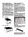
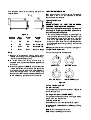
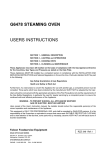
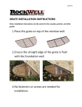
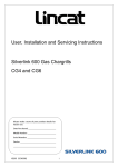
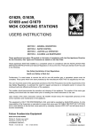
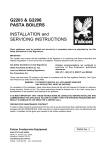
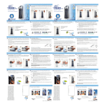
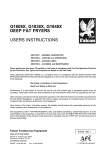
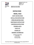
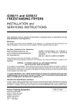
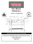
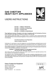
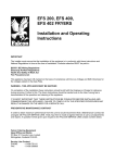
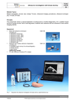
G350/9 and G350/10
CHARGRILLS
USERS INSTRUCTIONS
SECTION 1 - GENERAL DESCRIPTION
SECTION 2 - LIGHTING and OPERATIONS
SECTION 3 - COOKING HINTS
SECTION 4 - CLEANING and MAINTENANCE
These appliances have been CE-marked on the basis of compliance with the Gas Appliance Directive
for the Countries, Gas Types and Pressures as stated on the Data Plate.
These Appliances MUST BE installed by a competent person in compliance with the INSTALLATION AND
SERVICING INSTRUCTIONS and National Regulations in force at the time. Particular attention MUST be paid
to the following:
Gas Safety (Installation & Use) Regulations
Health and Safety at Work Act
Furthermore, if a need arises to convert the appliance for use with another gas, a competent person must be
consulted. Those parts which have been protected by the manufacturer MUST NOT be adjusted by the User.
Users should be conversant with the appropriate provisions of the Fire Precautions Act and the requirements of
the Gas Safety Regulations. in particular the need for regular servicing by a competent person to ensure the
continued safe and efficient performance of the Appliance.
Upon receipt of the User's Instruction manual, the installer should instruct the responsible person(s) of the
correct operation and maintenance of the Appliance.
This equipment is ONLY FOR PROFESSIONAL USE, and shall be operated by QUALIFIED persons. It is the
responsibility of the Supervisor or equivalent to ensure that users wear SUITABLE PROTECTIVE CLOTHING
and to draw attention to the fact that, some parts will, by necessity, become VERY HOT and will cause burns if
touched accidentally.
Falcon Foodservice Equipment
HEAD OFFICE AND WORKS
PO Box 37, Foundry Loan, Larbert.
Stirlingshire. Scotland. FK5 4PL
AFE SERVICELINE CONTACT PHONE - 01438 363 000
FAX - 01438 369 900
RZZ 102 Ref. 2
SECTION 2 - LIGHTING and OPERATIONS
The G350/9 and G350/10 simulated charcoal grills SETTING THE LAVA ROCK
SECTION 1 - GENERAL DESCRIPTION
are part of the Falcon 350 series of equipment. All
individual units comprising the series are of modular
dimensions, enabling suites of units to be installed in
a matching line whether counter-mounted, as are
these appliances, or floor-mounted i.e. ranges and
fryers.
The two models are similar in design, G350/9 unit is
350mm wide and G350/10 is 700mm wide.
G350/10 model has two burners, each individually
controlled by a safety tap: ignition being manual by
means of a taper. The G350/9 unit has a single
burner. The heat inputs are 19.2kW (70,000 Btu/hr)
and 9.6kW (32,750 Btu/hr) respectively.
The cooking surface consists of a number of cast iron
brander bars. (Three on G350/9 and Six on G350/10),
which can be used in any of four positions by
adjusting tilt handles and turning bars over.
During cooking process, excess fat is drained down
grooves in the bars into a removable fat drawer at
bottom of unit. Behind fat drawer is a removable drip
tray which collects lava rock remnants, food particles
etc.
Lava rock, sufficient for one filling, is supplied with
each appliance. It is important only to use lava rock
as supplied by Falcon.
DO NOT attempt to use ordinary charcoal etc.
Brander bars are lifted out to expose grates which will
carry the lava rock. Do not tip contents of bag of rock
on to grates. Place a single layer of lava rock over
grates. Spread evenly leaving spaces (as shown in
Figure 3) between pieces and covering entire grate
area. Discard any small chips of rock, as they may
lodge between grates and block heat flow. Excessive
rock will result in much of the gas burned being used
to overheat grates causing them to distort, or burn out
prematurely.
Important Note
Do not tip contents of the bag of rock directly onto
grates. The dust, which accumulates naturally at bag
bottom during shipment, must be discarded as it will
clog burner ports and affect performance.
THE FOLLOWING EXAMPLE SHOWS ROCK
DISTRIBUTION ON G350/10 (700mm WIDE)
Figure 1 - G350/9 Chargrill
Figure 2 - G350/10 Chargrill
BRANDER BARS
Brander bars, fitted in a set of three/six, have integral
drain channels (see Figure 4) which run fat released
during cooking into a collecting trough at front and
hence down to removable fat drawer.
Figure 4
The bars can be inverted i.e. they can be used with
rear flange facing down or up. Additionally, front ends
of bars can be positioned at two alternative heights by
manipulating tilt handles (see Figure 5).
This produces a total of four cooking positions, as
detailed below.
Cooking
Position
1
2
3
4
Notes
Figure 5
Rear
Front
Flange
Tilt
Up
Up
Down
Down
Up
Down
Up
Down
LIGHTING INSTRUCTIONS
Each tap controls an individual burner. To operate,
push knob in and turn it anti-clockwise to achieve
desired flame requirements.
Lighting The Burners
Warning
NEVER ATTEMPT TO LIGHT THE BURNERS
THROUGH THE SIMULATED CHARCOAL.
If pilot is extinguished intentionally or otherwise,
no attempt to re-light gas should be made until at
least 3 minutes have elapsed.
Brander
Angle
Horizontal
Minimum Slope
Moderate Slope
Maximum Slope
1. Position 4 is used when cooking foods which
release a lot of fat, thus causing excessive flaring,
if fat is not drained away quickly.
2. A limited amount of flaring and smoking is
desirable as this gives meat a better appearance
and flavour.
3. Dual cooking positions (G350/10 only) can be used
if three brander bars on one side are positioned
with rear flanges upward and the other three bars
have rear flanges down i.e. one side giving
Positions 1 or 2 while other side provide Positions
3 or 4, depending upon position of tilt handles.
1. Pull out fat drawer and apply a lighted taper up
through centre opening and light either left or right
pilot dependent upon which burner is required,
then turn on appropriate gas tap to ignition position
and push in. Hold knob in for a further 20 seconds
and release. Check through viewing window that
burner is lit.
2. Repeat for other burner, using other lighting port.
To Light The Main Burner
Turn control to high/low flame position.
OFF Position
IGNITION Position
FULL ON Position
LOW FLAME Position
Figure 6
To Turn The Burner OFF
For Short Periods
Turn gas tap to ignition position as shown in Figure 6,
hence leaving pilot lit.
For Longer Periods (i.e. OVERNIGHT)
Turn gas tap to off position, hence closing gas supply
to both main and pilot burners.
To Order Lava Rock
Contact Falcon or your nearest distributor/ agent.
Quote Spares No. 539113000 for ONE bag (1.75kg)
of lava rock.
G350/9 requires 1 bag of lava rock.
G350/10 requires 2 bags of lava rock.
SECTION 3 - COOKING HINTS
After lighting burners, allow unit to heat up for at least
30 minutes with burners full on to achieve correct
working temperature of lava rock and grid bars.
This is recognised when rock shows a red glow at
bottom, rock need not be red throughout and will be
giving off infra-red heat as required for fast cooking.
The gas can then be turned down but not more than
necessary to maintain the red glow in rock.
The temperature varies across depth of cooking grid:
The hottest area being at rear becoming
progressively cooler toward the front, enabling rare
and well done cooking to be achieved on steaks etc.
For good cooking, correct temperature and time are
very important. Thick cuts of meat etc, require a
longer cooking time at a lower temperature than
thinner cuts to avoid burning and should be cooked
nearer the front of the grids.
Steaks or chops should be branded on both sides to
retain their juices then cooked as required with as few
turns as possible. Rare cooking should be done at
rear of cooking area where food items will cook more
quickly on the outside. Attractive branding is
produced on food by the searing action of the hot
grid bar edges. A criss-cross pattern can be attained
by turning food through 90o halfway through cooking
process.
Fats dripping from meat will flare up on rock below
and flavour cooking. A certain amount of flaring
should occur to give this desirable flavouring but
should not be allowed to become excessive when
cooking fattier meats. When excessive flaring occurs,
lower tilting handles to run off excess fat and when
flaring subsides, return brander bars to original
position.
Cooking times vary considerably according to type of
food, thickness and customer requirements
i.e. RARE or WELL DONE, but experience will soon
produce satisfactory results.
For example: 100g high meat content beefburgers
can be cooked in 6 minutes (3 minutes per side) and
20mm thick, good quality steaks take from 5 minutes
(RARE) to 12 minutes (WELL DONE). These times
are not meant to be rigidly adhered to, they are for
general guidance only.
SECTION 4 - CLEANING and MAINTENANCE
Allow unit to cool before cleaning or removing parts.
The stainless steel external body should be cleaned
with soapy water as often as possible, rinse and dry.
Brander bars should be removed for cleaning with a
wire brush daily to prevent carbonising and to keep
drain channels clear.
Burners should be cleaned at least once a week to
maintain maximum performance. To do this, it is
necessary to first remove lava rock and burner
grates. The hearth surround should be removed by
lifting it upward. Burners are removed by lifting them
out rearward to avoid damaging injectors and are
best cleaned with a wire brush to remove deposits of
lava dust and grease which may block burner ports.
If allowed to accumulate, this will effect efficiency of
the appliance.
With hearth surround removed, the fat trough can be
lifted out and thoroughly washed, rinsed and dried.
Replacement of parts should be done in reverse
order. Ensure burners are dry and free from any
cleaning material before replacing.
Regular usage of appliance will dictate replacement
of the lava rock - approximately every six months.
Note
Should burner injectors become blocked, cleaning
should be carried out by an approved service
engineer.
The fat drawer should be removed, emptied and
thoroughly washed, rinsed and dried daily.
Periodic checks must be made during use to avoid
overflowing. Fat drawer should be removed by sliding
it forwards. Care should be taken in replacing fat
drawer to ensure it is pushed fully backwards into
correct position.
The drip tray behind fat drawer should be removed
regularly for cleaning. The tray is removed by sliding it
forward. Care must be taken when replacing it to
ensure the handles (large spacer brackets) are at
front of unit and that the tray is pushed fully backward
into correct position.