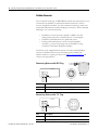
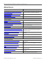
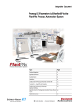
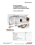
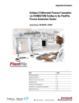
1
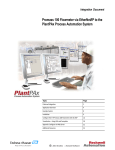
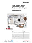
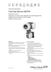
Integration Document
MicroPilot M Level-Radar via PROFIBUS PA
to the PlantPAx Process Automation System
Using a 1788-EN2PAR Linking Device
Topic
Page
Preferred Integration
2
Application Overview
4
MicroPilot M
6
Example System
10
Installation and Configuration
11
Visualization
55
Additional Resources
60
2
MicroPilot M Level-Radar via PROFIBUS PA to the PlantPAx Process Automation System
Preferred Integration
Rockwell Automation and Endress+Hauser have strengthened their strategic
alliance to provide complete process automation solutions that use best-inclass instrumentation, software, and control systems.
There are hundreds of different components in a typical plant: controllers,
remote I/O, electrical drives, safety equipment, and sensors. Each must be
integrated, configured, and optimized during start-up and operation.
Recognizing the challenges this creates, Rockwell Automation and
Endress+Hauser are focused on providing you with scalable, off-the-shelf
solutions.
Endress+Hauser
Rockwell Automation
To supply robust system solutions, Rockwell Automation pre-tests many
third-party manufactured HART, FOUNDATION Fieldbus, and PROFIBUS
PA field devices in the system test laboratory for compatibility with the
Rockwell Automation PlantPAx process automation system. Each field device
is connected to the PlantPAx system and is subjected to interoperability testing
procedures similar to operating procedures in your plant. The results of each
field test are recorded in a test report for integration planning purposes.
For Endress+Hauser field devices, an additional step provides an “Integration
Document” and “Interoperability Statement” for each tested instrument. The
Integration Document provides information on installation, configuration,
startup, and operation of the integrated system. The Interoperability Statement
is assurance that the Endress+Hauser field device meets PlantPAx system
interoperability performance measures, as jointly established by Rockwell
Automation and Endress+Hauser and verified through completion of common
test procedures performed by either company. Both the Integration Document
and Interoperability Statement help reduce risk with ease of integration.
RA Publication PROCES-AP026B-EN-P - July 2012
E+H Publication SP018A/04/en/13.12
MicroPilot M Level-Radar via PROFIBUS PA to the PlantPAx Process Automation System
3
The overall mission of the alliance is to provide you with proven solutions that
combine field instrumentation with fieldbus networks, such as HART,
FOUNDATION Fieldbus, and PROFIBUS PA networks, with asset
management capabilities and Rockwell Automation’s system capabilities to
provide a total engineered solution.
Through preferred integration and support of increasing requirements for
plant-wide control, the alliance offers the following benefits:
•
•
•
•
•
Reduced integration costs throughout engineering,
commissioning, and start-up
Optimized plant availability and output
Ensured product quality and consistency
Optimized traceability to meet regulatory demands
Predictive maintenance through intelligent instruments
For new construction, process improvements at an existing plant, or operating
cost reductions, the alliance delivers the following:
•
•
•
E+H Publication SP018A/04/en/13.12
Preferred integration reduces risk, reduces integration costs,
and protects investment with pre-engineered interoperability.
Both companies believe open systems and standardized
interfaces bring maximum benefits.
Advanced diagnostics with plant-wide control provides better
visibility of plant health and easier access to instrument
diagnostics, which ultimately leads to faster troubleshooting
and improves decision-making.
Collaborative lifecycle management leads to improvements in
design, engineering, and startup and support of plants. This
collaboration increases productivity, manages information
about instrumentation assets, optimizes plant assets, and
results in a complete lifecycle management solution.
RA Publication PROCES-AP026B-EN-P - July 2012
4
MicroPilot M Level-Radar via PROFIBUS PA to the PlantPAx Process Automation System
Application Overview
This document provides a step-by-step approach to integrating an
Endress+Hauser MicroPilot M via PROFIBUS PA into a Rockwell
Automation PlantPAx process automation system.
This Section
Describes
Application Overview
Details about the field instrument and control system.
System Details
Specifications on the required hardware and software components.
Installation
How to install and connect the instrument, linking device and other components.
Configuration
How to:
•
•
Visualization
RA Publication PROCES-AP026B-EN-P - July 2012
Configure the EN2PAR linking device.
Configure the measurement instrument.
How to implement and configure a graphical display of device information.
E+H Publication SP018A/04/en/13.12
MicroPilot M Level-Radar via PROFIBUS PA to the PlantPAx Process Automation System
5
The ControlLogix platform provides a robust EtherNet/IP backbone for
communication to process fieldbus networks. The PlantPAx architecture uses
producer/consumer technology, allowing input information and output status
to be shared by all ControlLogix controllers in the system. This integration
document assumes you have a working knowledge of ControlLogix systems.
For more details regarding the equipment and tasks described in this
document see additional resources.
This integration document assumes you have a working knowledge of
ControlLogix systems. For more details regarding the equipment and tasks
described in this document, see Additional Resources.
E+H Publication SP018A/04/en/13.12
RA Publication PROCES-AP026B-EN-P - July 2012
6
MicroPilot M Level-Radar via PROFIBUS PA to the PlantPAx Process Automation System
MicroPilot M Level-Radar
The Micropilot is a “downward-looking” measuring system, operating based
on the time-of-flight method. It measures the distance from the reference
point (process connection) to the product surface. Radar impulses are emitted
by an antenna, reflected off the product surface and received again by the
radar system.
The Micropilot M is used for continuous, non-contact level measurement of
liquids, pastes, slurries, and solids. The measurement is not affected by
changing media, temperature changes, gas blankets or vapors.
Your benefits:
•
•
•
RA Publication PROCES-AP026B-EN-P - July 2012
2-wire technology, low price:
A real alternative to differential pressure, floats and displacers.
2-wire technology reduces wiring costs and allows easy
implementation into existing systems.
High temperatures:
Suitable for process temperatures up to 200ºC (392ºF), up to
400ºC (752ºF) with high temperature antenna.
Rod antenna with inactive length:
Reliable measurement in narrow nozzles, with condensation
and build-up in nozzle.
Item
Description
E
Empty distance
F
Span (full distance)
D
Distance from sensor membrane – product surface
L
Level
E+H Publication SP018A/04/en/13.12
MicroPilot M Level-Radar via PROFIBUS PA to the PlantPAx Process Automation System
Measured Variables
The measured variable is the distance between a reference point and a
reflective surface (i.e. medium surface). The level is calculated based on the
tank height entered. The level can be converted into other units (volume,
mass) by means of linearization (32 points).
Signals from Instrument to Control System
PROFIBUS PA Interface
• PROFIBUS PA in accordance with EN 50170 Volume 2, IEC
61158-2 (MBP), galvanically isolated
• Current consumption: 16 mA
• Error current FDE (Fault Disconnection Electronic): 0 mA
• Signal encoding = Manchester II
• Function blocks: 4 x analog input, 2 x totalizer
• Output data: volume flow, mass flow, corrected volume flow,
heat flow, temperature, density, specific enthalpy, calculated
steam pressure (saturated steam), operating Z-factor, vortex
frequency, electronics temperature, Reynolds number, velocity,
totalizer
• Input data: positive zero return (ON/OFF), totalizer control,
pressure, display value
• Bus address can be set at the device via DIP switches
E+H Publication SP018A/04/en/13.12
RA Publication PROCES-AP026B-EN-P - July 2012
7
8
MicroPilot M Level-Radar via PROFIBUS PA to the PlantPAx Process Automation System
Control System
The control system includes these components:
Component
Description
Controller
The ControlLogix controller is a modular, high performance control that uses RSLogix 5000
programming software to configure, program, and monitor a system.
PROFIBUS PA linking
device
The 1788-EN2PAR is a PROFIBUS PA master linking device to an EtherNet/IP network for a
PROFIBUS PA field device network capable of supporting process instrumentation. It is a true PA
master, linking directly to the PA network with built in PA power conditioners. The EN2PAR and
PA field devices are added directly into the RSLogix 5000 I/O tree. The EN2PAR supports FDT
(Field Device Type) / DTM (Device Type Manager) technology.
The 1788-EN2PAR provides a fast and integrated solution for adding PROFIBUS PA field devices
to any Logix platform. This linking device provides a direct link between PROFIBUS PA and
EtherNet/IP with no intermediate PROFIBUS-DP layer required.
The module supports a maximum of 24 field devices and can supply a 500mA per trunk.
It will also allow the user to view detailed diagnostics from each field device using its DTM
(device type manager) directly from the Logix environment with Hiprom's FDT-ThinFrame. The
user will be able to view a scope trace of the signal of each field device and provide extended
statistics with regards to packet count (send, received, class 1, class2 etc.)
Programming
software
RSFieldbus and RSLogix 5000 are the software tools used to create the configuration that will
be stored in the Logix controller and the EN2PAR and provide access to cyclic data to and from
each field device. The AOP in RSLogix5000 is able to configure each instrument on the network,
transfer the configuration to the Logix controller and PA master which interpret the instrument
specific data structures.
Visualization software
FactoryTalk View Site Edition software is an HMI software program for monitoring, controlling,
and acquiring data from manufacturing operations throughout an enterprise. A generic display
provides a graphical representation via faceplates of the field instrument connected to the
EN2PAR linking device.
RA Publication PROCES-AP026B-EN-P - July 2012
E+H Publication SP018A/04/en/13.12
MicroPilot M Level-Radar via PROFIBUS PA to the PlantPAx Process Automation System
Asset management
software
FactoryTalk AssetCentre, with a fully scalable design, provides a set of asset-centric
focused tools for securely and centrally managing factory and process automation
production environments. It secures access to the control system, tracks users' actions,
managing asset configuration files, configuring process instruments, and provides
backup and recovery of operating asset configurations.
• Change management — management of security, configuration and archiving of
control assets.
• Process device management — calibration and configuration for process
instrumentation.
• Condition monitoring — predict or prevent impending failures of process
instrumentation with centralized device information.
• Disaster recovery — for all assets and devices.
FactoryTalk AssetCentre is based on the open, industry-leading FDT/DTM technology
integrated into the PlantPAx process automation system. It is a common environment
and launch application for Device Type Manager (DTM). An expanding library of Device
DTMs and an array of Communication DTMs are supported.
The optional smart device configuration tool, FieldCare, and the Life Cycle
Management tool W@M are Endress+Hauser’s plant asset management solution.
• Easy to implement and to scale up into existing infrastructure.
• Entire management of smart field devices supporting EtherNet, HART,
PROFIBUS, FOUNDATION Fieldbus and Wireless HART.
• Supports the entire device life cycle based on W@M starting with
engineering through ordering, installation, configuration, commissioning,
calibration, documentation management and spare parts handling.
• Endures technology migration by supporting all device DTMs and iDTMs for
DD based devices.
• Allows communication through third party systems supporting FDT/DTM
technology.
• Condition monitoring: used for preventive and predictive maintenance based
on diagnostic information from field devices.
FieldCare suite enables you to step into the asset management world with a sustainable
investment and offers the possibility to scale up to an integrated asset management
solution
E+H Publication SP018A/04/en/13.12
RA Publication PROCES-AP026B-EN-P - July 2012
9
10
MicroPilot M Level-Radar via PROFIBUS PA to the PlantPAx Process Automation System
Example System
Endress+Hauser and Rockwell Automation interoperability testing is
performed for every new device and product.
Hardware Components
Component
Catalog Number
MicroPilot M level-radar
FMR240-A2V1GNJCA5A
ControlLogix controller
1756-L75
Hiprom 1788-EN2PAR module
1788-EN2PAR
Stratix 8000 Switch
1783-MS10T
Power Supply AB
1606-XLE
Junction Box
1788-FBJB6 or FBJB4R
Ethernet Bridge
1756-EN2T
Software Components
Component
Catalog Number
RSLogix 5000 Enterprise Series programming 9324-RLD700NXENE
software, Professional edition
Includes:
• RSLinx Classic software
• RSLinx Enterprise software
FactoryTalk View Site Edition (SE) software
9701-VWSXXXXXENE
FactoryTalk AssetCentre server
9515-ASTSRVRENE
FactoryTalk AssetCentre process device
configuration
9515-ASTPRDCFENE
FieldCare Standard Asset Management
software (optional)
SFE500
HIPROM Profibus DTM for 1788-EN2PAR
AOP for EN2PAR
For specifications of the engineering workstation (EWS) and operator
workstation (OWS), see the Integrated Architecture for Process Control
System Recommendations Manual, publication PROCES-RM001.
See Additional Resources for complete installation instructions, including
warnings.
RA Publication PROCES-AP026B-EN-P - July 2012
E+H Publication SP018A/04/en/13.12
MicroPilot M Level-Radar via PROFIBUS PA to the PlantPAx Process Automation System
Installation and
Configuration
Installing a MicroPilot M Level-Radar
The following information is a summary of the installation procedures. See
Additional Resources for complete installation instructions, including warnings.
Connect a MicroPilot M Level-Radar
1. Unscrew housing cover (2).
2. Remove any display (3) if fitted.
3. Remove cover plate from terminal compartment (4).
4. Pull out terminal module slightly using pulling loop.
5. Insert cable (5) through gland (6). Use shielded, twisted pair.
6. Only earth screen conductor (7) on sensor side.
7. Make connection (see Pin Assignment).
8. Re-insert terminal module.
9. Tighten cable gland (6).
10. Tighten screws on cover plate (4).
11. Insert display if fitted.
12. Screw on housing cover (2).
E+H Publication SP018A/04/en/13.12
11
RA Publication PROCES-AP026B-EN-P - July 2012
12
MicroPilot M Level-Radar via PROFIBUS PA to the PlantPAx Process Automation System
Fieldbus Connector
The connection technology of PROFIBUS PA allows measuring devices to be
connected to the fieldbus via uniform mechanical connections, such as
T-boxes, distribution modules, etc. This connection technology, which uses
prefabricated distribution modules and plug-in connectors, offers substantial
advantages over conventional wiring.
•
•
•
Field devices can be removed, replaced or added at any time
during normal operation. Communication is not interrupted.
Installation and maintenance are significantly easier.
Existing cable infrastructures can be used and expanded
instantly; e.g., when constructing new star distributors using
4-channel or 8-channel distribution modules.
The device can be supplied with the option of a ready-mounted fieldbus
connector. Fieldbus connectors for retrofitting can be ordered from
Endress+Hauser as a spare part. Please see Endress+Hauser Support and
contact your representative.
Connecting Devices with M12 Plug
Cerabar M
+ –
–
+
M12
+ –
Item
Description
Left
Electrical connection for devices with M12 plug
Right
View of the plug at the device
Connecting Devices with 7/8” Plug
Cerabar M
–
+ –
7/8"
+
+ –
RA Publication PROCES-AP026B-EN-P - July 2012
Item
Description
Left
Electrical connection for devices with 7/8” plug
Right
View of the plug at the device
E+H Publication SP018A/04/en/13.12
MicroPilot M Level-Radar via PROFIBUS PA to the PlantPAx Process Automation System
13
Configuring the Device Address
•
•
•
•
Every PROFIBUS PA device must be given an address. If the
address is not set correctly, the device will not be recognized
by the process control system.
A device address may appear only one within a particular
PROFIBUS PA network.
Valid device addresses are in the range of 1 and 126. All
devices are delivered from the factory with the software
address 126.
The default address can be used to check the function of the
device and connect it to an operating PROFIBUS PA system.
Afterwards the address must be changed to allow other
devices to be connected to the network.
Hardware addressing comes into operation, when DIP switch 8 is in the
position “HW (OFF).” In this case the address is determined by the position
of DIP-switches 1 to 7 according to the table:
Switch No.
Value in position
“OFF”
Value in position
“ON”
1
0
2
0
3
0
4
0
5
0
6
0
7
0
1
2
4
8
16
32
64
The new address becomes valid 10 seconds after switching. It results in a new
device restart.
Note: Address setting via HIPROM CommDTM is currently not possible via
EN2PAR module.
E+H Publication SP018A/04/en/13.12
RA Publication PROCES-AP026B-EN-P - July 2012
14
MicroPilot M Level-Radar via PROFIBUS PA to the PlantPAx Process Automation System
Wire & Connect a Field Instrument to EN2PAR
The 1788-EN2PAR linking device is designed to operate within the Rockwell
Automation PlantPAx system using EtherNet/IP as the communication
backbone to the PROFIBUS PA process device network. All power required
for the module's operation is derived from an external 24V power supply. For
current consumption, please refer to electrical specifications in the EN2PAR
user manual.
The current status of the linking device is conveyed to the user by means of
the LCD display.
The following information is stored in the EN2PAR and is available to the
PlantPAx process automation system.
•
•
•
Eight Input process variables (PVs) and eight Output PVs
from up to 24 PROFIBUS PA field devices
Diagnostics from the 1788-EN2PAR module
Extended diagnostics of each PROFIBUS field device
The EN2PAR and field devices can be connected through a junction box
(complying with IEC61158-2), such as the 1788-JBFB4R or FBJB6.
RA Publication PROCES-AP026B-EN-P - July 2012
E+H Publication SP018A/04/en/13.12
MicroPilot M Level-Radar via PROFIBUS PA to the PlantPAx Process Automation System
15
Installation of the EN2PAR
Power
The 1788-EN2PAR requires 9 - 32V input to operate. The user has the option
to connect a second power supply (for redundant purposes) to the module. See
wiring below.
E+H Publication SP018A/04/en/13.12
RA Publication PROCES-AP026B-EN-P - July 2012
16
MicroPilot M Level-Radar via PROFIBUS PA to the PlantPAx Process Automation System
PROFIBUS PA
The PROFIBUS PA network must be connected via the PA terminal on the
module. The pin-out is as follows:
Pin
Description
Right
PA +
Middle
PA -
Left
Shield
The PA cable color code is used as set in IEC61158-2 Physical Layer
Specification.
RA Publication PROCES-AP026B-EN-P - July 2012
E+H Publication SP018A/04/en/13.12
MicroPilot M Level-Radar via PROFIBUS PA to the PlantPAx Process Automation System
17
Configure the Linking Device Ethernet Address
The module will connect to an Ethernet network using a RJ45 connector. The
module will ship with BOOTP enabled. Thus the user can set the IP address
using a BOOTP server or using the hardware switches. The hardware switches
is located under the front cover as shown below. The Page button is used to
toggle between different diagnostics on the display.
In this application, the Ethernet Port is used to connect the Linking Device to
the ControlLogix system using the 1756-EN2TR.
E+H Publication SP018A/04/en/13.12
RA Publication PROCES-AP026B-EN-P - July 2012
18
MicroPilot M Level-Radar via PROFIBUS PA to the PlantPAx Process Automation System
Module will boot with IP address: 192.168.1.091.
Note: Modify the address if necessary. For this example we used 91.
Module will boot with BOOTP enabled.
For normal operation the switches must be set to “000”.
Software
The user will need the following software to configure and use the
1788-EN2PAR:
•
•
Add-on Profile (AOP)
1788-EN2PAR Device Type Manager (DTM)
Both the applications can be found on the product CD or the Hiprom
Technologies website: www.hiprom.com.
Note: To install the AOP and DTM, go to the Hiprom site and download.
Then open RSLogix 5000.
RA Publication PROCES-AP026B-EN-P - July 2012
E+H Publication SP018A/04/en/13.12
MicroPilot M Level-Radar via PROFIBUS PA to the PlantPAx Process Automation System
19
Configuring the System Using RSLogix 5000
The following are the steps required to build a PROFIBUS PA tree in RSLogix
5000 Setup.
Note: Using RSWho Active in RSLinx or RSLogix and verify the active
devices. See the example screen below.
E+H Publication SP018A/04/en/13.12
RA Publication PROCES-AP026B-EN-P - July 2012
20
MicroPilot M Level-Radar via PROFIBUS PA to the PlantPAx Process Automation System
1. Open RSLogix and select File > New.
2. Create a new project.
3. Click and the New Controller screen appears. Select and enter the data.
4. Click OK and create an RSLogix project in the I/O configuration.
RA Publication PROCES-AP026B-EN-P - July 2012
E+H Publication SP018A/04/en/13.12
MicroPilot M Level-Radar via PROFIBUS PA to the PlantPAx Process Automation System
21
Note: Using the I/O configuration utility you will select modules and Add
IP address. For this example the 1756-EN2T is set to 192.168.1.8
and the 1788-EN2PAR Linking Device to 192.168.1.91.
5. From the I/O tree select New Module and add the EN2T. Click
Create and set up the Ethernet bridge.
E+H Publication SP018A/04/en/13.12
RA Publication PROCES-AP026B-EN-P - July 2012
22
MicroPilot M Level-Radar via PROFIBUS PA to the PlantPAx Process Automation System
6. Using the I/O configuration utility, select module and enter the IP
address of 192.168.1.8 for the EN2T
Note: Press Enter after each entry.
7. Click OK and select New Module again /Communications and
select the Linking Device.
Note: To add the 1788-EN2PAR the user must select the module type
when adding it under Allen-Bradley Ethernet bridge as shown above.
RA Publication PROCES-AP026B-EN-P - July 2012
E+H Publication SP018A/04/en/13.12
MicroPilot M Level-Radar via PROFIBUS PA to the PlantPAx Process Automation System
8. Then select the device as shown below and click Create.
9. Enter a name, set up the EN2PAR address 91 and click OK.
E+H Publication SP018A/04/en/13.12
RA Publication PROCES-AP026B-EN-P - July 2012
23
24
MicroPilot M Level-Radar via PROFIBUS PA to the PlantPAx Process Automation System
The screen should look similar to the following.
When added, the module requested packet interval (RPI) will default to
300ms. If needed, the user can change the RPI depending on the field device
count and update times required.
Note: The RPI will determine the amount of Class 1 data requests send for
the field devices configured on the PA Bus. Thus if there are many
field devices configured on the bus and the RPI is set too low, the
field devices will not be able to update in time and all acyclic PA data
will be slow as Class 1 data is prioritized. Please see Class 2 MPPF in
the master configuration.
Once the module is added to the tree the user can open the properties by rightclicking on the device and selecting the Properties option. Once the properties
window is open select the Configuration tab to open the 1788-EN2PAR
configuration page. For Example settings adding the EN2PAR to the I/O
profile. Add the name and address of the device.
RA Publication PROCES-AP026B-EN-P - July 2012
E+H Publication SP018A/04/en/13.12
MicroPilot M Level-Radar via PROFIBUS PA to the PlantPAx Process Automation System
Note: If not already connected, connect up the PC and go online with
RSLogix5000. Under the communication tab select Who Active.
Using Who Active, select the proper processor.
10. Select or click Download and then Go Online.
E+H Publication SP018A/04/en/13.12
RA Publication PROCES-AP026B-EN-P - July 2012
25
26
MicroPilot M Level-Radar via PROFIBUS PA to the PlantPAx Process Automation System
11. If the following screen appears click Download again.
12. Select Yes when complete and verify the online screen status.
RA Publication PROCES-AP026B-EN-P - July 2012
E+H Publication SP018A/04/en/13.12
MicroPilot M Level-Radar via PROFIBUS PA to the PlantPAx Process Automation System
13. Right-click on the 1788-EN2PAR in the I/O tree and then select
Properties. Then left click and the following screen appears.
14. Select the Configuration tab and under Master (1) configuration.
E+H Publication SP018A/04/en/13.12
RA Publication PROCES-AP026B-EN-P - July 2012
27
28
MicroPilot M Level-Radar via PROFIBUS PA to the PlantPAx Process Automation System
15. Click Scan Network.
16. Select GSD file.
Note: If the above screen appears then the GSD files are loaded.
17. Select the Scan Network button and the following screen should
appear. If new device is found click OK.
RA Publication PROCES-AP026B-EN-P - July 2012
E+H Publication SP018A/04/en/13.12
MicroPilot M Level-Radar via PROFIBUS PA to the PlantPAx Process Automation System
29
Note: The following steps 18.-21. are used only if new GSD files are
required. If not, go to step 22.
18. Select the Process Catalog button. This will launch the Process Utility
that manages the GSD files and DTMs. Thus if the user loaded new
DTMs or GSD files the Process Utility must be launched and the
libraries must be updated. The following should appear:
19. The Process utility opens. Select Profibus PA, add, and compile the
GSD file.
20. When complete, devices with GSD files will be displayed in the left
pane.
Note: The default device settings shown can be changed. Refer to the
device manual. The user will not be able to configure a field device
for cyclic communication unless the GSD file is in the Process
Utility Catalog and the catalog has been updated as shown below.
21. Select OK.
E+H Publication SP018A/04/en/13.12
RA Publication PROCES-AP026B-EN-P - July 2012
30
MicroPilot M Level-Radar via PROFIBUS PA to the PlantPAx Process Automation System
22. Select Download.
23. When completed, select Status and select PV Data Path.
The following should appear with live data. All appropriate fields should be
green.
RA Publication PROCES-AP026B-EN-P - July 2012
E+H Publication SP018A/04/en/13.12
MicroPilot M Level-Radar via PROFIBUS PA to the PlantPAx Process Automation System
31
Once the user is happy with the configuration it can be downloaded to the
1788-EN2PAR. The device will save the configuration in non-volatile memory.
If the power is cycled then the module will use the last configuration saved.
24. Click the Download icon.
Note: Any changes will only take effect once it has been downloaded to the
1788-EN2PAR module.
Note: If the user is not certain about the format of the PV please refer to
the user manual of the field device being used.
25. If required, from the Online properties screen, select Configuration
and the user can choose the format clicking on the drop-down menu
and selecting as shown in the example below.
See Additional Resources or Chapter Signals from Instruments to
Control System for CHANNEL assignment.
26. Return to the Overview.
E+H Publication SP018A/04/en/13.12
RA Publication PROCES-AP026B-EN-P - July 2012
32
MicroPilot M Level-Radar via PROFIBUS PA to the PlantPAx Process Automation System
Device Type Manager (DTM)
The DTM can be used either in the profile with the ThinFrame or using a
FDT Frame (eg. AssetCentre or FieldCare).
Note: The ThinFrame can only view diagnostics of the field device. The
user will need a FDT frame to configure and parameterize the field
device.
1. Select Process Catalog and launch the DTM Tool.
2. The user must first update the DTM catalog by launching the Process
Utility and selecting update as shown below. When complete click OK.
Note: This update is only required once or when new devices are added.
3. After the update is complete, the user can select the DTM simply by
selecting the correct DTM from the list.
RA Publication PROCES-AP026B-EN-P - July 2012
E+H Publication SP018A/04/en/13.12
MicroPilot M Level-Radar via PROFIBUS PA to the PlantPAx Process Automation System
33
4. Hit OK. Save and Close the project then reopen the project and Go
On-Line.
5. Right-click on the EN2PAR and select Properties to Open the AOP
and go to the device configuration tab.
6. From the AOP configuration tab select Process Catalog.
E+H Publication SP018A/04/en/13.12
RA Publication PROCES-AP026B-EN-P - July 2012
34
MicroPilot M Level-Radar via PROFIBUS PA to the PlantPAx Process Automation System
7. Then select DTM and DTM Viewer.
8. Verify the communication DTM and close.
9. Select the Advanced tab.
RA Publication PROCES-AP026B-EN-P - July 2012
E+H Publication SP018A/04/en/13.12
MicroPilot M Level-Radar via PROFIBUS PA to the PlantPAx Process Automation System
10. Open the DTM drop-down list and select the proper DTM.
11. Click Open DTM, Go Online and select open DTM and select
Online Parameterize.
E+H Publication SP018A/04/en/13.12
RA Publication PROCES-AP026B-EN-P - July 2012
35
36
MicroPilot M Level-Radar via PROFIBUS PA to the PlantPAx Process Automation System
12. Select Standard View and Measuring Values.
Note: This is a view-only screen.
The instrument configuration is complete. Don’t forget to save the project.
RA Publication PROCES-AP026B-EN-P - July 2012
E+H Publication SP018A/04/en/13.12
MicroPilot M Level-Radar via PROFIBUS PA to the PlantPAx Process Automation System
37
Verify Operation using RSLogix
Each 1788-EN2PAR consumes a total of 4 connections from the Logix
Controller regardless of the field device count. Thus the input and output
image of each 1788-EN2PAR is divided into four sections A to D. The first
connection will have the PA Master Data added as well.
Using the AOP to monitor online data:
1. In the RSLogix 5000 tree, select Controller Tags. Look up and select
the EN2PAR:IA, monitor tags then select Master.
E+H Publication SP018A/04/en/13.12
RA Publication PROCES-AP026B-EN-P - July 2012
38
MicroPilot M Level-Radar via PROFIBUS PA to the PlantPAx Process Automation System
If a field device is online and running (exchanging cyclic data) then its field
device index bit in (the connection status) will be set. If the device goes offline
the bit will be cleared.
2. Select Field Device 0 and click Data. Each field device will display its
PA diagnostics as well as all available PVs and their status, as shown in
the example below:
3. Close RSLogix.
RA Publication PROCES-AP026B-EN-P - July 2012
E+H Publication SP018A/04/en/13.12
MicroPilot M Level-Radar via PROFIBUS PA to the PlantPAx Process Automation System
39
Connect to, Monitor and Configure the Instrument via AssetCentre
AssetCentre from Rockwell is the FDT-based plant asset management
software tool that lets you configure the intelligent field instruments from
E+H. An optional tool called Fieldcare is also available from E+H. See page
50.
Note: Before starting make sure the DTM's have been imported and
installed for the Hiprom Communication linking device and the E+H
Instrument. To access the DTMs and other software download them
from the Hiprom and or E+H websites.
1. Install the appropriate DTMs.
2. Start-up AssetCentre and open a new project.
3. Update the DTM catalog under Tools. Click DTM Catalog and verify
that the DTMs exist in the catalog.
E+H Publication SP018A/04/en/13.12
RA Publication PROCES-AP026B-EN-P - July 2012
40
MicroPilot M Level-Radar via PROFIBUS PA to the PlantPAx Process Automation System
4. Left click and verify that the DTMs now exist in the catalog. Scan if
necessary.
5. Close the DTM catalog and set up the DTM network path under
Tasks.
6. Select the DTM network and click.
RA Publication PROCES-AP026B-EN-P - July 2012
E+H Publication SP018A/04/en/13.12
MicroPilot M Level-Radar via PROFIBUS PA to the PlantPAx Process Automation System
7. Select the DTM network and right click to add the DTM to the
HSnetwork. Or select Add DTM.
8. Select the HS Ethernet network and click OK.
E+H Publication SP018A/04/en/13.12
RA Publication PROCES-AP026B-EN-P - July 2012
41
42
MicroPilot M Level-Radar via PROFIBUS PA to the PlantPAx Process Automation System
9. Select the network and click Add DTM.
10. Select 1788-EN2PAR, and then click OK.
11. Add the IP addresses and hit Enter after entry.
RA Publication PROCES-AP026B-EN-P - July 2012
E+H Publication SP018A/04/en/13.12
MicroPilot M Level-Radar via PROFIBUS PA to the PlantPAx Process Automation System
12. Hit Next.
13. Click Scan Network. The Scan Results screen should appear.
E+H Publication SP018A/04/en/13.12
RA Publication PROCES-AP026B-EN-P - July 2012
43
44
MicroPilot M Level-Radar via PROFIBUS PA to the PlantPAx Process Automation System
14. Verify the information, click OK, then click Close.
15. Click Design and from the AssetCentre Asset view select Process
Area.
16. Right-click then select New and click.
RA Publication PROCES-AP026B-EN-P - July 2012
E+H Publication SP018A/04/en/13.12
MicroPilot M Level-Radar via PROFIBUS PA to the PlantPAx Process Automation System
45
17. Then from the Process Area tree, go to Process Devices and select
the Instrument.
18. Click OK. The screen should appear.
E+H Publication SP018A/04/en/13.12
RA Publication PROCES-AP026B-EN-P - July 2012
46
MicroPilot M Level-Radar via PROFIBUS PA to the PlantPAx Process Automation System
19. Enter a Name (Example: Instrument) and click OK.
20. Right-click on Instrument or (other name), then select Properties
and click Enter.
RA Publication PROCES-AP026B-EN-P - July 2012
E+H Publication SP018A/04/en/13.12
MicroPilot M Level-Radar via PROFIBUS PA to the PlantPAx Process Automation System
47
21. Select DTM addressing info and click the key on the right-hand side of
the screen.
22. From the following screen highlight the Instrument.
E+H Publication SP018A/04/en/13.12
RA Publication PROCES-AP026B-EN-P - July 2012
48
MicroPilot M Level-Radar via PROFIBUS PA to the PlantPAx Process Automation System
23. Click OK and the following screen should appear.
24. Click OK.
25. Highlight “Instrument” and select DTMView.
RA Publication PROCES-AP026B-EN-P - July 2012
E+H Publication SP018A/04/en/13.12
MicroPilot M Level-Radar via PROFIBUS PA to the PlantPAx Process Automation System
49
A screen showing the instrument’s data will appear.
26. Select the Online view and open. Make any changes to settings if
necessary.
27. Close the DTMs and AssetCentre.
28. Open RSLogix 5000 and open the Project.
29. If desired, Go Online and Open the Controller Tag database. Select
the project name tags or instrument tags to display device, status and
diagnostic data.
E+H Publication SP018A/04/en/13.12
RA Publication PROCES-AP026B-EN-P - July 2012
50
MicroPilot M Level-Radar via PROFIBUS PA to the PlantPAx Process Automation System
Connect to, Monitor and Configure the Instrument via FieldCare
FieldCare is the FDT-based plant asset management software tool that lets you
configure the intelligent field instruments.
Note: Before starting make sure the DTM's have been imported and
installed for the Hiprom Communication linking device and the
E+H Instrument. To access the DTMs and other software,
download them from the Hiprom and or E+H websites.
1. Install the appropriate DTMs.
2. Start FieldCare and open a new project.
3. Choose the DTM Catalog menu and click Update.
RA Publication PROCES-AP026B-EN-P - July 2012
E+H Publication SP018A/04/en/13.12
MicroPilot M Level-Radar via PROFIBUS PA to the PlantPAx Process Automation System
51
4. If there are DTMs listed in the dialog box´s left pane, select desired
DTMs and click Move or choose “Add all to DTM catalog”.
If you do not find the desired DTMs, or if the left pane of the dialog box is
empty, click Update. FieldCare searches for DTMs installed on your computer.
After search, found DTMs are added to the dialog box´s left pane.
If necessary, to remove DTMs, select the desired DTMs in right pane and click
Move.
Click OK to save your changes.
E+H Publication SP018A/04/en/13.12
RA Publication PROCES-AP026B-EN-P - July 2012
52
MicroPilot M Level-Radar via PROFIBUS PA to the PlantPAx Process Automation System
6. Click the Add Device icon, select HS EtherNet/IP DTM and click
OK.
RA Publication PROCES-AP026B-EN-P - July 2012
E+H Publication SP018A/04/en/13.12
MicroPilot M Level-Radar via PROFIBUS PA to the PlantPAx Process Automation System
53
7. Click on HS EtherNet/IP- DTM. Click the Add Device icon, select
1788-EN2PA-R and click OK.
8. To configure the 1788-EN2PA-R, double click on 1788-EN2PA-R in
the left pane.
9. Enter the 1788-EN2PA-R IP address and the Max Scan Address.
E+H Publication SP018A/04/en/13.12
RA Publication PROCES-AP026B-EN-P - July 2012
54
MicroPilot M Level-Radar via PROFIBUS PA to the PlantPAx Process Automation System
10. Click the Create Network icon.
11. When prompted click OK. The Com DTM now scans the entire
PROFIBUS PA network behind the 1788-EN2PA-R and searches for
the right DTM. If the right DTM is installed, the instrument comes up
in the Explorer view on the left pane.
If only one DTM is added to the network, the Software automatically goes
online. Otherwise a warning occurs that must be confirmed. To switch this
behavior off, in the Explorer- context- menu Extras/Options, select After
Scanning within Page Scanning.
12. In an open FieldCare project, right-click on the instrument in the left
pane and select Connect.
13. Double-click on the instrument in the left pane. The Online
parameterization window appears with the Instrument Health Status.
The following example shows a Prowirl field instrument. Your screens
may vary depending on the field instrument.
14. You can right-click now on the instrument in the left pane to access
other views and data, e.g. observe, reset or offline parameterization.
RA Publication PROCES-AP026B-EN-P - July 2012
E+H Publication SP018A/04/en/13.12
MicroPilot M Level-Radar via PROFIBUS PA to the PlantPAx Process Automation System
Visualization
55
In order to monitor the instruments using the pre-designed faceplates, the
EN2PAR must be set up as specified in this integration document and the
manual. We also suggest developing a similar configuration to the one included
in the RSLogix 5000 project provided by Rockwell Automation. The controller
exchanges data between the devices, and the FactoryTalk View SE faceplates
notify personnel what is happening in the plant.
The following information summarizes the Add-On Instructions and
faceplates. See Additional Resources for more detailed information.
Add-On Instructions
An Add-On Instruction exchanges data between each process variable located
in the process device and the faceplate installed on a display. The name of the
specific instance of the Add-On Instruction becomes the link from the actual
instrument to the faceplate on the graphic.
Structured input data for each field instrument.
IMPORTANT
E+H Publication SP018A/04/en/13.12
The P_AIn_PA Add-On Instruction uses embedded P_MODE and
P_ALARM Add-On Instructions. These embedded Add-On Instructions
must already be in the project before importing the P_AIn_PA Add-On
Instruction.
RA Publication PROCES-AP026B-EN-P - July 2012
56
MicroPilot M Level-Radar via PROFIBUS PA to the PlantPAx Process Automation System
Global Object
A global object links the tag name to the faceplate, provides a touch area from
which to launch the faceplate, and displays the process variables and alarms.
IM PORTANT
RA Publication PROCES-AP026B-EN-P - July 2012
A unique global object and faceplate are available for each field
instrument due to each instrument having specific extended
diagnostics.
E+H Publication SP018A/04/en/13.12
MicroPilot M Level-Radar via PROFIBUS PA to the PlantPAx Process Automation System
57
Faceplates
The FactoryTalk View SE generic display provides a graphical representation
of the instrument based on the information within each Add-On Instruction.
Navigation buttons at the top of the faceplate change the information
displayed. Status displays show information using a bar graph, numeric values,
and trend displays. Other displays show specific alarms and warning
indications.
Here are some examples of predesigned faceplates.
E+H Publication SP018A/04/en/13.12
RA Publication PROCES-AP026B-EN-P - July 2012
58
MicroPilot M Level-Radar via PROFIBUS PA to the PlantPAx Process Automation System
IM PORTANT
A unique global object and faceplate is available for each field
instrument due to the display of instrument-specific extended
diagnostic information.
The faceplates provide the following from the device:
•
•
•
PROFIBUS PA process values (PV) - first, second, third,
fourth, fifth, sixth, seventh, eighth from instrument
PV fault status (communication fault)
PROFIBUS PA device Extended Status
Configure the faceplates to provide the following:
•
•
•
•
•
•
•
•
•
PROFIBUS PA PV range (minimum and maximum)
Tag name
Description
Engineering units
Mode (such as operator or program)
High-high, high, low, low-low alarms
Over-range and under-range alarms
Alarm delay
Alarm hysteresis
Extended Diagnostic Messages
PROFIBUS PA Extended Diagnostic Status provides information about an
instrument when an instrument's transmitter or sensor is not running properly.
It produces bit-based outputs that can be translated into specific error codes in
order to help maintenance personnel determine more specific details about
abnormal conditions with PROFIBUS PA instruments.
RA Publication PROCES-AP026B-EN-P - July 2012
E+H Publication SP018A/04/en/13.12
MicroPilot M Level-Radar via PROFIBUS PA to the PlantPAx Process Automation System
Configure the Micropilot M
Level-Radar
E+H Publication SP018A/04/en/13.12
59
Configure via Quick Setup Menus on the Local Display of the field
instrument, use the Quick Setup menus to configure instrument parameters.
RA Publication PROCES-AP026B-EN-P - July 2012
60
MicroPilot M Level-Radar via PROFIBUS PA to the PlantPAx Process Automation System
Additional Resources
Resource
Description
PROFIBUS PA Field Instruments
Micropilot M FMR230/231/240/244/245 Technical Information,
publication TI000345F/00/en
Specifications and details of the MicroPilot M Radar Level.
Micropilot M FMR230 PROFIBUS PA Operating Instructions,
publication BA225F/00/en
How to install, wire, configure, and operate a MicroPilot M Radar
Level.
www.products.endress.com/profibus-gsd
Download GSD file for field instrument.
http://www.products.endress.com/flow
Information about Endress+Hauser flowmeters
Controller Components
ControlLogix Controllers Installation Instructions, publication
1756-IN101
How to install and configure a ControlLogix controller.
ControlLogix Controllers User Manual, publication 1756-UM001
How to configure, operate, and maintain a ControlLogix controller.
HIPROM EN2PAR User Manual
Describes the functionality, installation, configuration, and
operation of the EN2PAR module.
http://www.hiprom.com
Download firmware updates and updated documentation.
Operator Components
Add-On Instructions and Faceplates for Visualizing PROFIBUS PA
Instrument Data in FactoryTalk View SE, Knowledgebase document
(Login required. Please contact your sales representative.)
How to implement the PROFIBUS PA Add-On-Instruction in
controller logic to work with the FactoryTalk View faceplates for
PROFIBUS PA instruments.
FactoryTalk View Site Edition User's Guide, publication
VIEWSE-UM006
How to design, develop, and deploy FactoryTalk View SE
applications.
Faceplates, Add-On Instructions, project files, etc. (Login required.
Please contact your sales representative.
Download AOIs, Faceplates and Global Object graphics, and project
files.
www.products.endress.com/fieldcare
Information about FieldCare Asset Management software.
www.products.endress.com/dtm-download
Information about field instrument DTMs.
Process Control Information
PlantPAx Reference Manual, publication PROCES-RM001
Provides characterized recommendations for implementing the
PlantPAx System
PlantPAx Selection Guide, publication PROCES-SG001
Information for assisting in selecting equipment for a PlantPAx
system
Process Objects Library Manual, publication PROCESRM002
PlantPAx process objects library information
http://www.rockwellautomation.com/process
Information about Rockwell Automation process control and
Integration Documents.
http://literature.rockwellautomation.com
Available Rockwell Automation publications, including Integration
Documents.
http://www.endress.com
Information about Endress+Hauser field instruments.
RA Publication PROCES-AP026B-EN-P - July 2012
E+H Publication SP018A/04/en/13.12
Rockwell Automation Support
Rockwell Automation provides technical information on the Web to assist you in using its products. At
http://support.rockwellautomation.com, you can find technical manuals, a KnowledgeBase of FAQs, technical and application
notes, sample code and links to software service packs, and a MySupport feature that you can customize to make the best use of
these tools.
For an additional level of technical phone support for installation, configuration, and troubleshooting, we offer TechConnect
support programs. For more information, contact your local distributor or Rockwell Automation representative, or visit
http://support.rockwellautomation.com.
Endress+Hauser Support
Please refer to your local Endress+Hauser Sales Center for precise information regarding the service support available in your area
or visit http://www.endress.com.
Installation Assistance
If you experience a problem within the first 24 hours of installation, please review the information that's contained in this manual.
You can also contact a special Customer Support number for initial help in getting your product up and running.
United States
1.440.646.3434
Monday – Friday, 8 a.m. – 5 p.m. EST
Outside United States
Please contact your local Rockwell Automation representative for any technical support issues.
New Product Satisfaction Return
Rockwell Automation tests all of its products to ensure that they are fully operational when shipped from the manufacturing
facility. However, if your product is not functioning and needs to be returned, follow these procedures.
United States
Contact your distributor. You must provide a Customer Support case number (call the phone
number above to obtain one) to your distributor in order to complete the return process.
Outside United States
Please contact your local Rockwell Automation representative for the return procedure.
Allen-Bradley, ControlLogix, FactoryTalk, PlantPAx, Rockwell Automation, RSLinx, RSLogix 5000, and TechConnect are trademarks of Rockwell Automation, Inc.
Trademarks not belonging to Rockwell Automation are property of their respective companies.
E+H Publication SP018A/04/en/13.12
Copyright © 2012 Endress+Hauser, Inc.
RA Publication PROCES-AP026B-EN-P - July 2012
Copyright © 2012 Rockwell Automation, Inc. All rights reserved. Printed in the U.S.A.