1
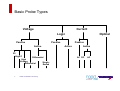
Critical Considerations for Probing
Agenda
Types of Probes
Probe Selection Criteria
How Probes Affect Your Measurement
Choosing a Probe
2
Critical Considerations for Probing
Types of Probes
Probes: Critical Elements of the Measurement System
4
Critical Considerations for Probing
Basic Probe Types
Current
Voltage
Logic
Passive
Passive
Active
Optical
Passive
Active
Active
Z0
High Z
Differential
High
Voltage
SingleDifferential
Ended
5
Critical Considerations for Probing
AC DC
AC
Passive Voltage Probes
Most basic probe with no active components
Available in 1X, 2X, 10X, 100X and switchable
Advantages
–
–
–
–
Inexpensive
Mechanically Rugged
Wide Dynamic Range
High Input R
Disadvantages
– High Input C
– Inductance of long ground lead
Tektronix P2220 Probe
1/10X, 200 MHz
Tip
Cable
LGround Lead
Probe
6
Critical Considerations for Probing
Active Voltage Probe
Uses active components
Advantages
–
–
–
–
Low Input C
Wide Bandwidth
High Input R
Better Signal Fidelity
Disadvantages
– Higher Cost
– Limited Dynamic Range
– Mechanically Less Rugged
LGround Lead
7
Critical Considerations for Probing
Probe
Tektronix TAP1500
Active Voltage Probe
10X, 1.5 GHz
Differential Active Voltage Probes
Differential Probes measure signals that are
referenced to each other instead of earth
ground.
Advantages
–
–
–
–
Wide bandwidth
Large Common Mode Rejection Ratio (CMRR)
Minimal skew between inputs
Small input capacitance
Input 1
+
_
Input 2
Probe
8
Critical Considerations for Probing
VOUT
Scope
Channel
Amplifier
Scope
Tektronix TDP0500 and TDP1000
Differential Probe
500 MHz or 1 GHz, 42V
Current Probes
Measures the electromagnetic flux field around
a conductor to determine the current flow
Two Major Types:
– AC current probes (passive)
– AD/DC current probes (active)
Features to Consider:
– Automatic scaling and units
– Split-core vs. fixed-core connection
to the device
Tektronix TCP0150
AC/DC Current Probe
150 A, DC to 20 MHz
9
Critical Considerations for Probing
Logic Probes
The MSO4000B Series Oscilloscope
offers 16 digital channels
Recommend the P6616 digital probe:
10
–
16 Channels, 2 Groups of (8) channels
–
First coax in each group is colored blue
for easy identification
–
Standard automotive spade connection
for the common ground
–
3 pF loading
Critical Considerations for Probing
Tektronix P6616
iCapture™ - One Connection for Analog and Digital
iCapture™ (Analog Mux)
–
–
Acquire digital channels with digital time resolution (80ps)
Simultaneously route any (4) digital channels to analog channels
–
Validate signal connection
–
Check signal integrity
–
Validate logic threshold
–
Improve timing resolution
Digital
Channels
+
-
C
A0
Analog
Channels
D0
Analog
Mux
+
+
-
Critical Considerations for Probing
Digital
2.5 GHz Analog
Full Bandwidth
Analog
Probe Selection Criteria
What is Your Probe Selection Process?
The first one you spot in a drawer
Distract a co-worker and take theirs
13
Critical Considerations for Probing
What is Your Probe Selection Process?
Original signal
Signal at probe
tip is changed
Signal at the
oscilloscope
Signal display
with DSP
correction
Deliver a Signal to the Scope with Good Fidelity
14
Critical Considerations for Probing
The Ideal Probe
Absolute Signal Fidelity
Rin = ∞
Cin = 0
CABLE
No affect on the
original signal
Easy to connect
No affect on the original signal – No signal source loading!
– Zero Input Capacitance
– Infinite Input Resistance
Absolute Signal Fidelity
–
–
–
–
Unlimited bandwidth “zero to infinity”
Unlimited rise time “instant – 0 s”
Zero attenuation “one-to-one”
Linear phase across all frequencies
A convenient and easy way to connect to the device-under-test
– Mechanically well suited to application
15
Critical Considerations for Probing
The Measurement System (Scope and Probe)
No easy formula to calculate
Measurement System
specifications
Tektronix provides
specifications for scope &
probe combinations
For best results, use the
probes recommended for
your scope
16
Critical Considerations for Probing
I2C (Physical Part)
+V
Pull-up resistors
SDA
SCL
Master
Critical Considerations for Probing
Device
3
Device
4
CAN is a differential BUS
CAN High Speed Differential Bus
Signal
Tx
Rx
CAN_H
CAN
Controller
Rx
CAN_L
CAN Physical Layer
Tx
dominant
Electronic
Control
Unit
CAN-H
3.5V
1
2.5V
0
1
1.5V
CAN-L
recessive
Tx
+ +
- -
Critical Considerations for Probing
path
+
+
-
-
Rcv
recessive
Differential & Floating Measurements
A differential measurement is the difference in voltage levels between
two input signals.
For a floating measurement, neither input is at ground potential.
Differential Measurement
V1
Unit
Under
Test
VMeas
Floating Measurement
Unit
Under
Test
VMeas
V2
V1
Earth Ground
V1 = Single-ended Measurement
V2 = Single-ended Measurement
VMEAS = V1 + Inverse (V2)
19
Critical Considerations for Probing
V1
Earth Ground
VMeas = Measured Voltage between
2 probed points
V1 = Offset Voltage above true ground
Differential Measurements with Single-ended Probes
Poor CMRR
– Inaccurate measurement (combination of offset and gain)
– Noisier measurement
Skew
– Amplitude and timing errors
V1
Skew
VMeas =
V1 + [ Inv (V2) +
CMRR or Skew]
V2
20
Different Offset or gain
Critical Considerations for Probing
Deskew is a Source of Error
Deskew is important when measuring:
– Pseudo-differential (CH1 + (Inv (CH2))
– Timing/Propagation Delay
Include Probe adapters in deskew adjustment
If possible, use the same probe family
Deskew Fixture
Deskew
7.40 ns
21
Critical Considerations for Probing
Result of “Floating” Measurements with Ground Connection
22
Critical Considerations for Probing
How Probes Affect Your Measurement
Critical Considerations for Probing
Probes Will Affect Your Measurement
Signal Source Loading
– Measurement system’s impedance is critical
– Input Resistance
– Input Capacitance
– Inductance
Signal Fidelity
– Measurement system parameters also crucial
– Bandwidth
– Rise Time
Good Signal Fidelity
CABLE
Minimize affect on
the original signal
Easy to connect
24
Critical Considerations for Probing
Signal Source Loading
When the probe is connected to the DUT, the probe will draw some current.
The impedance values of the probe and scope will affect the measured signal.
The Measurement System impedance (Z) consists of:
– Resistive Elements (Resistance, R)
– Reactive Elements (Capacitance, C and Inductance, L) which vary over frequency
Good probe design uses R, L, and C elements to influence signal fidelity, attenuation,
and source loading over specified frequency ranges.
Z
Z
Device Under Test (DUT)
25
Critical Considerations for Probing
Test
Point
Z
Measurement System
(Probe and Scope)
Source Loading – Input Resistance
Rin acts like a voltage divider
Higher input resistance – less loading
Lower source resistance – less loading
DUT
Rsource
Probe
Probe Tip
RIn
Esource
LGround Lead
100%
90%
100%
90%
10%
0%
10%
0%
Source Signal
26
CIn
Critical Considerations for Probing
Decreased Signal Amplitude
Rin
Vmeas = Vsource
Rin + Rsource
Effects of Input Resistance
Source Loading – Input Capacitance
Smaller input capacitance - higher probe impedance, less loading
As signal frequency increases, capacitance increases and loading increases
DUT
Rsource
Probe
RIn
Esource
CIn
LGround Lead
100%
90%
100%
90%
10%
0%
10%
0%
Example:
Cin = 100 pF
tr ~ 220 nsec
Cin = 10pF
tr ~ 22 nsec
If Rsource = 1 kΩ
Source Signal
27
•Decreased Amplitude
•Phase Change
•Slower Rise Time
tr ~
~ 2.2(Rsource x Cin)
Probe Tip
Critical Considerations for Probing
Effects of Input Capacitance
Source Loading - Inductance
The longer the ground lead, the higher the probe inductance.
Keep ground leads as short as possible to avoid ringing!
Probe Tip
Rsource
Resonance
(Ringing)
RIn
Esource
LGround Lead
100%
90%
100%
90%
10%
0%
10%
0%
Source Signal
28
CIn
Critical Considerations for Probing
Effects of Inductance
Resonance:
How Does Added Inductance Affect the Measurement?
Trise of 1 ns ~ 350 MHz BW Equivalent
0.05 - 0.1 µH
(combined typical)
Ring Frequency Using
a 1.5 pF Input Capacitance
10X High Z Active Probe
and 6” Ground Lead.
For a 10X Active Probe with Cin = 1.5 pF
and a 6”Ground Lead
=
Critical Considerations for Probing
350 MHz
to
500 MHz
Calculating Resonant Frequency
Resonant Frequency =
1
2π LC
In practice, the resonant frequency should be >5 times the signal’s
BW equivalent based on rise and /or fall times. This gives a
guideline to the maximum inductance (or maximum allowable
probe-connection loop.)
Rules of Thumb:
L ≈ 20 nH/inch for typical lead lengths around 0” - 3”
(probe tip and ground lead)
C ≈ Probe rated C plus 1 to 2 pF/inch of added lead length
(probe tip)
Critical Considerations for Probing
Probing Tips and Tricks:
Ground Lead Length Effects
Coaxial Cable
3” Ground Lead
31
Critical Considerations for Probing
BNC Probe Tip Adapter
1” Ground Adapter
6” Ground Lead
No Ground Lead
Signal Fidelity – Rise Time
Insufficient rise time also affects the signal
To accurately characterize your signal, follow the 1/5th Rule
Tr, system < Tr,signal
5
Measured rise time depends on the signal and scope rise times
Tr,Measured =
(Tr,signal)2 + (Tr, system)2
Actual
32
Critical Considerations for Probing
Measured
Low-Capacitance Passive Voltage Probing
Comparison of
different probes
and compensation
capabilities
very different
results
Source of error
Critical Considerations for Probing
Probing Tips and Tricks:
Probe Adapters will Affect the Measurement
Ease of connectivity and signal fidelity are a trade-off.
Accessories may impact rise time and cause aberrations.
Source Through 50 Ohm
Terminator + 1 MOhm CH 1
TDP1000 Square Pin
P6139A w/ 1” Z Lead
P6139A w/ 1” Z Lead
(Incorrect LF Comp)
P6139A w/ Short Spring
Ground
34
Critical Considerations for Probing
Probe Accessories - The Connection to the DUT
Connects the Probe to
the DUT
Adjustment tools
Marker bands
9-digit part numbers are
found on the web or in
the User Manual
Probe Tip Adapters
Ground Leads
(Short and Long)
Attachment Klips
Square Pin Adapters
Solder Down Adapters
35
Critical Considerations for Probing
Example Probe Loading
Active Differential Probe
Showing Various Adapter
(e.g Square Pin Adapter)
Critical Considerations for Probing
Reference Signal vs. Probe Output
Green = probe loading
(SMA output)
Blue =
Probe output
White = stored Reference
Signal
Critical Considerations for Probing
Effect of Square Pin Adapter
Critical Considerations for Probing
Reference Signal vs. Probe + Square Pin Adapter + Pins
Green = probe loading
(SMA output)
Blue =
Probe output
White = stored Reference
Signal
Critical Considerations for Probing
Signal Fidelity – Bandwidth Limitation
Complex signals contain many spectral components that cumulatively form a
signal over time.
– Spectral components are sine waves at varying frequencies and varying
amplitudes which are added together to collectively form one signal.
To accurately characterize your signal, follow the 5 Times Rule
BW of system > 5 x Fundamental Frequency
Fundamental (1st Harmonic)
3rd Harmonic
5th Harmonic
Fourier Square Wave (1st – 5th)
40
Critical Considerations for Probing
Signal Fidelity – Bandwidth Limitation
30% Amplitude error is true for a repetitive sine wave.
Amplitude
Actual Signal
3%
10%
20%
30%
Frequency
Measured Signal
What if you aren’t measuring a repetitive sine wave?
41
Critical Considerations for Probing
Signal Fidelity – Bandwidth Limitation
Insufficient bandwidth affects the signal
Amplitude
– Why is the front edge affected? The front edge contains the high
frequency content.
– If the measurement system doesn’t have enough bandwidth, it won’t
capture the high frequency portion of the signal.
3%
10%
20%
30%
Frequency
42
Critical Considerations for Probing
The signal
delivered to the
oscilloscope
Insufficient BW
degrades the
front edge
Voltage Probes: Bandwidth Limiting Filters
Some voltage probes provide bandwidth limiting filters to remove
unwanted high-frequency signal content.
43
Critical Considerations
Considerations for
for Probing
Probing
Critical
© 2011 Tektronix
3/11
Tektronix Confidential
Current Probe Degauss
Removes residual magnetic flux from probe’s magnetic components
High impact of measurement result (blue current waveform before and after “degaussing”)
Capability of measuring DC (Hall-Element) and AC Signal Components simultaneously
Critical Considerations for Probing
Choosing a Probe
Critical Considerations for Probing
Choosing The Right Probe
Carefully Consider Your Application:
–
–
–
–
–
–
Type of signal – voltage, current, single-ended, differential…
Signal frequency content (bandwidth issue)
Signal rise time
Source impedance (R and C)
Signal amplitudes (maximum and minimum)
Test point geometries
Choose a probe specified for your scope!
46
Critical Considerations for Probing
TekVPI® – Tektronix Versatile Probe Interface
Smart communication between
oscilloscope and probe
–
–
–
Automatic units displayed
Nominal deskew of signal paths
Probe menu on oscilloscope
interacts directly with probe
Provides more power to probes
–
–
47
Enables greater flexibility in probe
combinations
Enables direct connection to
current probes (including ac/dc),
differential probes, and singleended active probes without
external amplifiers
Critical Considerations for Probing
TekVPI Highlights
Comp box controls provides easy and convenient access to controls
and indicators plus:
– Enhanced gain compensation increases accuracy
– Stored propagation delay speeds critical deskew procedures
– Auto degauss and probe offset autozero insures repeatable measurements
Advanced Remote Control is ideal for manufacturing test applications
TekVPI to TekConnect Adapter
Critical Considerations for Probing
TekProbe to TekVPI Adapter
Breakthrough in Passive Probing
Mechanical
Key
ASIC + Probe = Perfect Match
Custom ASIC inside the oscilloscope is matched to the probes
Probe notifies oscilloscope what type of probe it is via TekVPI
– Sets input in oscilloscope to special path (not 1MΩ or 50 Ω)
Scope can optimize signal input path to remove differences in hardware
– AC compensation across frequency band
Mechanical keying so TPP0500 and TPP1000 cannot be plugged into an
oscilloscope without the matched ASIC
Critical Considerations for Probing
Low-Capacitance Passive Voltage Probing
Industry leading 3.9pF capacitive loading
TPP1000 step response with greater
bandwidth and improved flatness
TPP0500: 500 MHz passive voltage
probe
– Standard with 350 MHz and 500 MHz models
P6139A step response showing longer
settling time and lower bandwidth
TPP1000: 1 GHz passive voltage probe
– Standard with 1 GHz and 2 GHz models
Multiple ground connections included
– Six inch ground lead
– Short spring clip ground leads
AC calibration routine optimizes
frequency response
Application usage
– Digital system debug
Half the loading with twice the bandwidth
Critical Considerations for Probing
Low-Capacitance Passive Voltage Probing
automated Procedure
frequency response
adjustment
High accuracy results
Critical Considerations for Probing
Voltage Probes Specifications
Critical Considerations for Probing
Differential Probe Capabilities
Selectable attenuation factors
Excellent CMRR capabilities
Low noise floor
Reduced probe loading effects
Selectable bandwidth limiting filters
DC Reject / AC coupling to eliminate the
DC offset in the measured signal
Remote access and control
Versatile DUT connectivity accessories.
Small Probe head
Status Indicator
TDP Probes
Critical Considerations for Probing
Differential & Floating Measurements
Characteristic
TMDP0200
THDP0200
THDP0100
Attenuation
25X/250X
50X/500X
100X/1000X
Differential
Voltage
250X: +/- 750 V
25X: +/- 75V
500X: +/- 1500 V
50X: +/- 150 V
1000X: +/- 6000 V
100X: +/- 600 V
+/- 750 V
+/- 1500 V
+/- 6000 V
550 V CAT I
300 V CAT III
200 MHz
1000 V CAT II
600 V CAT III
200 MHz
2300 V CAT I
1000 V CAT III
100 MHz
Rise Time
< 1.8 ns
< 1.8 ns
< 3.5 ns
Slew Rate
< 275 V/ns
@ 1/250 gain
< 650 V/ns
@ 1/500 gain
< 2500 V/ns
@ 1/1000 gain
Input Impedance
at the Probe Tip
5 MΩ || < 2 pF
10 MΩ || < 2 pF
40 MΩ || < 2.5 pF
DC: > - 80 dB
1 MHz: > - 60 dB
3.2 MHz: > - 30 dB
50 MHz: > - 26 dB
DC: > - 80 dB
1 MHz: > - 60 dB
3.2 MHz: > - 30 dB
50 MHz: > - 26 dB
DC: > - 80 dB
1 MHz: > - 60 dB
3.2 MHz: > - 30 dB
50 MHz: > - 26 dB
1.5 m
1.5 m
1.5 m
Common Mode
Voltage
Max Input Voltageto-Earth
Bandwidth
Common Mode
Rejection Ratio
Cable Length
54
Critical Considerations for Probing
TCP0030 AC/DC Current Probe
Accurate and simplified current measurements by TCP0030 AC/DC current probe
–
Wide Dynamic Range
–
–
DC to 120 MHz Bandwidth
–
–
Measures 1mA to 30A
Captures high frequency harmonic components
TekVPI Probe Architecture
– Connects directly to the DPO7000 Series oscilloscopes
– User setups controlled via the Probe Compensation box buttons and LED indicators or via
the easily accessible Scope Probe Menu
– Remote programmable probe control via GPIB, USB or Ethernet
Critical Considerations for Probing
TCP0030 AC/DC Current Probe
Critical Considerations for Probing
Current Probes Specification
Critical Considerations for Probing
How do I probe serial digital buses?
Digital buses are not digital
Digital signals do not
necessarily have only
two discrete levels
Digital probes are not digital
Everything you know about
analog probing still applies
– Minimize DC and AC loading
– Voltage measurements are
always differential
– Minimize lead inductance
Bus and Waveforms display of I2C signal
The real signal must be delivered to the oscilloscope’s hardware or
software comparator, where it can be compared to the digital
threshold value(s)
Critical Considerations for Probing
Digital Bus Analysis with Logic Probes
Specification
DPO4000B / MSO5000
Maximum Sample Rate
Maximum Input Toggle Rate
DC Input Voltage Range
Maximum Input Voltage Swing
Input Impedance
Input Capacitance
Threshold Range
Minimum Input Swing
Minimum Detectable Pulse
color-coded
waveform
display
Critical Considerations for Probing
bus decode
500MS/s
16.5GS/s with MagniVu
500 MHz
± 42 Vpeak
30 Vp-p ≤200MHz
10 Vp-p >200 MHz
100 kOhm
3 pF
± 40 V
400 mVp-p
1 ns
What do the probing and acquisition architectures look like
Passive probe A
Digital input circuit
(logic analyzer ASIC)
front-panel
connector
0.2pF
coax
3pF
+
100kΩ
Passive probe B
6pF
300Ω
90.9kΩ
2pF
Critical Considerations for Probing
acquisition circuit
Acquisition
System
Digital input circuit
(discrete design)
Twisted pair
cable
acquisition circuit
front-panel
connector
10k
Vth
+
-
Acquisition
System
Logic Probe Specifications for iCapture™
P6780 Differential Probe
P6750 D-Max Probe
P6717A General Purpose Probe
Analog Bandwidth 2.5 GHz
1 GHz
Input Impedance
20 kΩ ± 1.0%, 3 pF
40 kΩ ± 2.0%
(differential-mode), 0.5pF
Input Voltage
Range
-2V to +4,5V
Critical Considerations for Probing
- 1,5V to +4V
P6780 Probe Access to Tightly Spaced Test Points
Industry’s only differential active
probes for MSOs
– Excellent signal fidelity
Industry’s best versatility in
access points
– Device Leads
– Solder-in
– VIA’s and Traces
– BGA packages
– Square Pins
Reduces fixturing costs and
development time
Critical Considerations for Probing
P6780 Probe and Accessories
Critical Considerations for Probing
High Bandwidth Solder-In Probing Solutions
Socket Cable
020-2954-xx
TriMode Micro-Coax Tip
4GHz
P75TRLST Solder Tip
up to 20GHz
P7500 Series
Tri-Mode Probes
Critical Considerations for Probing
Accessories - Flexible Solutions
New tips solder to small vias
Critical Considerations for Probing
Selection on Oscilloscope Screen for the used Adapter
Selection of different
probe tips
Clean signals, high
fidelity with the best
probes available
Optimize performance
for the signal-path
scope/probe/tip
66
Critical Considerations for Probing
BGA Chip Interposer for Oscilloscopes
Unique Socket Design allows for multiple chip exchanges
– Solder-in version is also available
Recommended probes: P7500 Series
– New TriMode™ solder tips matched to Interposer (order #020-3022-00)
– Interposer has embedded 100Ω resistors near BGA balls
– in place of probe tip resistors
– Designed as a Probe-Interposer System
Critical Considerations for Probing
BGA Chip Interposer for Oscilloscope
BGA Chip Interposer
(with and without Chip-Socket)
Component Interposer on DDRModule
Interposer with Probe Tip for DQ, DQS
and CLK
Critical Considerations for Probing
Component Interposer with Chip Interposer on DDRModule
68
Summary
Probes are a critical element of your
measurement system
To maximize measurement accuracy,
carefully choose your probe;
–
–
–
–
Type of signal
Bandwidth
Rise time
Impedance
Tektronix offers a wide range of probes
and accessories to meet your needs
69
Critical Considerations for Probing
Tektronix Probe Selector
Visit:
www.tektronix.com/probes
70
Critical Considerations for Probing