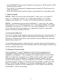
1
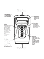
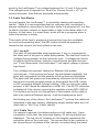
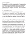
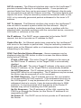
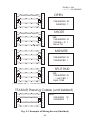
LanScaperf Network Tester
User's Guide
www.jdsu.com/know
RJ45 Jack - Connect to
cable or jack to be tested
Link Indicator
On when network
link is established.
Back-lit LCD 2 lines by 16
characters w/
icons
LINK
PASS FAILCALSETUPTEST
1 2 3 4 5 6 7 8 S ID
MADE IN USA
Curser Keys Used to scroll
through options,
set addresses and
adjust values
SEL
CABLE
SETUP
Sel Key
Select key is used
to enter displayed
operating mode,
start a new test,
change the value
of an option, enter
sub-menus or
move to the next
screen
(Depending on
context)
NTWRK
PWR
Power Key
Press PWR to turn
on the LanScaper
in the mode at
power off. Further
presses of PWR
toggle the back light
on and off.
Hold down to turn off
Battery Cap - Press down
with heel of hand to open
Mode Key
Press CABLE for
cable modes, press
NTWRK
for network modes
or press the center
(both at once) for
SETUP
mode
Table of Contents
1.0 INTRODUCTION�������������������������������������������������������������������������������� 1
1.1 Cautions��������������������������������������������������������������������������������������� 1
1.2 Features��������������������������������������������������������������������������������������� 1
1.3 Kit Contents��������������������������������������������������������������������������������� 2
1.4 Using this Manual������������������������������������������������������������������������ 2
1.5 Network Connectivity������������������������������������������������������������������� 2
2.0 STEP BY STEP USE INSTRUCTIONS��������������������������������������������� 3
2.1 To ID an Unknown Jack or Plug��������������������������������������������������� 3
2.2 To Test Cables Only��������������������������������������������������������������������� 3
2.3 To Place Tone on a Cable������������������������������������������������������������ 3
2.4 To Measure Length of a Cable����������������������������������������������������� 4
2.5 To Locate an Ethernet Port���������������������������������������������������������� 4
2.6 To PING Devices on a Network��������������������������������������������������� 4
2.7 To Validate a Cable Link by Functional Testing���������������������������� 5
2.8 To Change PING Addressing Mode�������������������������������������������� 5
3.0 FUNCTIONAL DESCRIPTION����������������������������������������������������������� 6
3.1 Voltage Check������������������������������������������������������������������������������ 6
3.2 Cable Test Modes������������������������������������������������������������������������ 7
3.2.1 Jack ID�������������������������������������������������������������������������������� 7
3.2.2 Cable Test�������������������������������������������������������������������������� 7
3.2.3 Cable Length���������������������������������������������������������������������� 8
3.2.4 Tone Generator������������������������������������������������������������������ 8
3.3 Network Test Modes�������������������������������������������������������������������� 9
3.3.1 Flash Link LED������������������������������������������������������������������� 9
3.3.2 PING Test��������������������������������������������������������������������������� 9
3.3.3 Validate Link��������������������������������������������������������������������� 13
4.0 SETUP MODE���������������������������������������������������������������������������������� 15
4.1 Target Setup Sub-Menu������������������������������������������������������������� 15
4.2 PING Setup Sub-Menu�������������������������������������������������������������� 16
4.3 Last DHCP��������������������������������������������������������������������������������� 16
4.4 DHCP On/Off����������������������������������������������������������������������������� 17
4.5 MAC add������������������������������������������������������������������������������������ 17
4.6 Units-Feet/Meters���������������������������������������������������������������������� 17
5.0 STATUS AND ERROR MESSAGES FOR NETWORK TEST
MODES�������������������������������������������������������������������������������������������������� 18
6.0 INTERPRETING CABLE TEST RESULTS�������������������������������������� 21
Table of Contents
7.0 Models, options & accessories����������������������������������������� 23
8.0 MAINTENANCE������������������������������������������������������������������������������� 24
8.1 Battery Replacement����������������������������������������������������������������� 24
8.2 To Reset the processor�������������������������������������������������������������� 24
9.0 SPECIFICATIONS���������������������������������������������������������������������������� 25
10.0 CUSTOMER SERVICES���������������������������������������������������������������� 26
Appendix A: Glossary of Networking Terms�������������������������������������� 29
Appendix B: Internet Protocol Definitions����������������������������������������� 32
1.0 INTRODUCTION
1.1 Cautions
Warning!
Do not attach to primary power lines. The LanScaper™ may be
damaged and cause a safety hazard. When connecting to an unknown
jack or plug, the LanScaper™ should be off. Once connected, press
CABLE button to ID the connection.
Caution!
Improperly crimped, damaged or un-crimped plugs can damage the jack
on the LanScaper™. Inspect plugs for proper termination and crimping
before inserting into the tester. Contacts on a plug should always be
recessed into the plastic grooves. Do not use with standard 6 position
plugs (RJ11/RJ12), the LanScaper™ jack may be damaged. Use the
provided “no fault” (green transparent plugs) 6 position RJ cable, which
can be connected to 6 or 8 position jacks without causing any damage.
Note: The screen comes with a clear , peel-off protective coating
over the LCD screen that should be removed for clearest view of the
display.
1.2 Features
• Jack ID mode:
• Capable of identifying many of the possible conditions of an
RJ45 jack
• Automatically runs cable test if no active devices found
• Cable Test Mode:
• Single-ended testing of cables for shorts, opens and split pairs
(no remote on other end)
• Full cable test finds all wiring faults including split pairs with a
remote connected
• Results displayed in wire map format with a message line for
shorts and split pairs
• Displays PASS icon for T568A/B passing cables and reports
cable length
• Length measurement in feet or meters using cable capacitance method
• Tone generator mode for use with tone tracers
• Flash Link LED mode sends tone while blinking a link indicator to find a
HUB or switch port
• PING mode:
• Simultaneously PINGs three devices at once: a target, a router
and a DNS server
• DHCP protocol support allows for PINGing of a router and DNS
server with no setup
• Auto-MDI/MDI-X like protocol makes connection to HUB, switch or NIC
with any patch cable
• Two line by 16 character full alphanumeric backlit LCD with icons for
clear test results
• Auto-off in any mode and low power consumption for long battery life
1.3 Kit Contents
NT700 - Basic kit comes with LanScaper™ main unit in a Cordura™
case, (1)- cable test remote, (2)- 1 foot patch cables, (2)- RJ45 to
alligator clip cables, (2)- “no fault” RJ12 cables and documentation.
NT750 - Complete kit comes with LanScaper™ main unit, (8)- cable
test remotes, (1)- TT100 tone tracer, (2)- 1 foot patch cables, (2)- RJ45
to alligator clip cables, (2)- RJ45 to F-connector adapters, (2)- “no fault”
RJ12 cables and documentation in a zippered Cordura™ case with
space for entire contents of the kit.
1.4 Using this Manual
The next section gives step by step use instructions for each function. If
you are unfamiliar with network and internet terminology, read over the
Glossary of Networking Terms and Internet Protocol Definition sections
beginning on page 18.
For detailed description of each function, see the Functional Description
section. Interpreting Cable Test Results and Error Messages sections are
useful reference sections.
1.5 Network Connectivity
The LanScaper™ uses IP address protocol and recognizes AutoNegotiation using Fast Link Pulses to report advertised Ethernet
capability. LanScaper™ also supports a modified version of auto MDI/
MDI-X to allow for connection to a HUB, switch or NIC with a straight
through cable. The LanScaper™ operates using 10 base-T for all
network transmissions. The vast majority of 100 base-T Fast Ethernet
products support 10 base-T. However, should a HUB or switch be 100
base-T only through settings or by design, a different port, a change
of settings or insertion of an inexpensive 10/100 HUB in line with the
LanScaper™ will be necessary.
2.0 STEP BY STEP USE INSTRUCTIONS
To turn the LanScaper™ off after any test, press and hold PWR button
until the display turns off. The tester will turn off automatically after about
15 minutes in all modes except Tone Generator, which is 60 minutes, and
Flash Link LED, which is 30 minutes. When connecting to unknown jacks
or cables, it is best to begin with the power off and turn the LanScaper™
on after the connection is made. This insures that the voltage check will
be run first before any other testing.
2.1 To ID an Unknown Jack or Plug
1) With LanScaper™ powered off, connect to unknown jack or plug.
2) Press CABLE button, LanScaper™ will power on in Jack ID mode
and determine what device is connected to the other end of the cable
or test the cable if no connection is found.
2.2 To Test Cables Only
Skips the ID portion of the Jack ID test above.
1) Connect one end of cable run to be tested to LanScaper™. Press
CABLE button repeatedly until Cable Test is displayed (twice if unit
was off). Press SEL button to enter test.
2) If the cable is connected while the tester is on, a single-ended test
for shorts, opens and split pairs will most likely be in progress. Press
SEL button to force a new test to begin.
3) For a complete test, connect a remote to the other end of the cable.
Application Hints: Any patch cables used to connect the tester and
remote to a cable run must be short compared to the cable run for
accurate open and split pair indication, no more than 10% of the total run
length or 3 feet, whichever is less. A cable must be at least 4 feet long
for single-ended test to work properly.
2.3 To Place Tone on a Cable
1) Connect cable to be traced to main unit. Turn on tester by pressing
CABLE button. Press CABLE button until Tone Generator is
displayed, than press SEL button.
2) Press SEL until desired tone is selected. The up/down arrow keys
select the pin or pair(s) to carry the tone.
3) For strongest signal, do not connect remote. Due to the shielding
effect of twisted pairs, the strongest signal is obtained by having one
wire of a pair carry tone. Selecting a single pin instead of a pair will
do this.
2.4 To Measure Length of a Cable
1) Connect cable to main unit. A remote may be at the other end, but is
not required.
2) Turn on unit by pressing CABLE button. Press CABLE button until
Cable Length is displayed, then press SEL button. To change length
units between feet and meters, use setup mode.
3) Press up/down arrows to adjust length constant. If length constant
is unknown for a particular cable, a known length of cable may be
used to set the constant. Fifty feet or more is suggested to minimize
the resolution error (1 foot in 50 is 2% uncertainty). Connect known
cable to tester and change the cable constant using up/down arrows
until the length reads correctly.
2.5 To Locate an Ethernet Port
1) With LanScaper™ powered off, connect LanScaper™ to a jack or
plug at the workstation location for which the Ethernet port is to be
located.
2) Press NTWRK button, LanScaper™ will power up in the Flash
Link LED mode and connect to the Ethernet port on a HUB, switch
or NIC. Even if no connection is made, tone is generated on the
cable to aid in finding the cable with a tone tracer at the other end
(equipment closet).
3) If an Ethernet link is active on the cable the LanScaper™ turns on
its link LED and begins flashing it in unison with the link indicator
on a port of the HUB, switch or NIC at the other end. Tone is also
generated on the cable in this condition, but at a different cadence to
indicate having established a link.
2.6 To PING Devices on a Network
If the jack or plug is unknown, run Jack ID test first. The PING function
operates in two modes DHCP On and Off (Manual). This is selected
in SETUP by the DHCP On/Off option. No other entries are required to
establish communications with a router and a DNS server on a DHCP
network. To PING a specific target (Tg1-4), the address must be entered
and the desired target address selected in SETUP before starting the
PING test. In DHCP Off mode, all IP configuration information must be
entered in SETUP first.(PING Setup option)
1) With LanScaper™ powered off, connect to network.
2) Press NTWRK button repeatedly until PING Test is displayed on
screen (two presses when off). Press SEL button to enter test.
Several status screens will be displayed while establishing a link and
negotiating the DHCP configuration. Once PINGing begins, a PING
status screen will be displayed, showing acronyms for each active
conversation.
3) Press left or right arrows to move curser ( ) next to a device
acronym. Press SEL button to view more information about a device.
There are a total of three screens to view. Press SEL button to
advance to the next screen or the screen will advance automatically
after 10 seconds.
2.7 To Validate a Cable Link by Functional Testing
Two LanScaper™ testers can be used to exercise a cable link with no
additional equipment being required. This can also be done through a
HUB or switch with or without any other equipment being present. The
two LanScapers™ will be referred to as the Validator and the PING
Generator. The Validator uses the Validate Link mode and the PING
Generator uses PING Test mode.
1) Connect the Validator to one end of the link to be tested.
2) Press NTWRK button until Validate Link is displayed. Press SEL
button to activate test.
3) In SETUP, set PING Generator to DHCP Off (see To Change PING
Addressing, below). A specific manual address does not need to
be set, the PING Generator will recognize the Validator and assign
addressing.
4) Connect the PING Generator to the other end of the link.
5) On the PING Generator, press NTWRK button until PING Test is
displayed and press SEL button to begin.
6) The target or router acronym will change to Val on the PING
Generator when the Validator is found and addressing assigned. The
PING Generator operates and accumulates information as in the
normal PING Test. The Validator displays a packet count only on its
screen.
2.8 To Change PING Addressing Mode
Other options are changed similarly.
1) Turn on LanScaper™ by pressing PWR button and press the middle
of the CABLE/NTWRK button, which is marked SETUP. The percent
battery remaining screen will appear briefly.
2) Press down arrow button three times, DHCP On or DHCP Off should
be displayed.
3) Press SEL button to toggle between on and off. Displayed value is
current setting.
4) Press CABLE or NTWRK to exit to a test or press and hold PWR
button to power off.
3.0 FUNCTIONAL DESCRIPTION
The LanScaper™ is a jack identifier, cable tester and PING tester in one
tester. The LanScaper™ has a backlit LCD display and eight momentary
buttons. The rubber end cap at the bottom is the battery compartment
cover.
The LanScaper™ is powered on by pressing any one of three buttons:
PWR, CABLE or NTWRK. The tester will turn on in the last mode used
before turning off if the PWR button is pressed. If the CABLE button
is pressed, the tester immediately starts executing the Jack ID test.
Pressing the NTWRK button causes the Blink Link LED test to begin.
The LanScaper™ is turned off by holding down the PWR button until the
display goes blank. The tester will also shut off automatically 15 minutes
after the last button press in most modes, 30 minutes in Blink Link LED
mode and 60 minutes in Tone Generator mode. Short presses of the
PWR button, toggles the back light on and off. The back light turns off
automatically about 5 minutes after being turned on. Using the back light
increases power consumption by between 20% and 50%.
There are eight test modes and a setup function as described below.
The mode switch is the double button immediately above PWR. The top
button is labeled CABLE, the bottom button is labeled NTWRK and the
area bridging the two button is labeled SETUP. Pressing a mode button
will immediately end any currently running task and either begin the
executing the first task of a new category (cable or network) or display
the next mode in the same category, waiting for a press of SEL to begin
the testing. Subsequent presses in the same category advances to the
next mode, rolling over to the first mode when the end is reached, still
waiting for SEL to begin.
3.1 Voltage Check
All tests, except Jack ID, start with a check for voltages on the pins on
the tester’s jack. If found, the message “-Voltage Found- SEL Jack ID”
is displayed, and the only option for the user is to press the SEL key to
start the Jack ID test to determine what type of interface or what voltages
are present on the jack. The tester monitors the jack to see if the voltage
is removed for five minutes. The selected test will continue if the voltage
is removed, or the tester will shut itself off after the five minutes. The
exception to this behavior is in the Network Modes. When voltage is
found in these modes, the tester checks to see if it is Ethernet Phantom
Power. This is a voltage which is connected to the center taps of the
Ethernet interface transformers of some network equipment to power
remote devices, like IP phones or wireless transceivers. This power is
seen by the LanScaper™ as voltage between the 1-2 and 3-6 pin pairs.
The voltage found is reported as “Enet Pwr Source Found = xV” for
several seconds, then the test proceeds automatically.
3.2 Cable Test Modes
In most modes, the LanScaper™ is constantly testing and reporting
results. While it is recommended that an unknown jack connection is
always verified by connecting to the tester while it is powered off, it is fine
to attach a known network or dead cable or jack to the tester while it is
running. In that case, it is most likely, a test will be in progress when a
cable connection is made.
The results of the test in progress at connection time are unreliable.
In most such repeating tests, the SEL button should be pressed to
terminate the current test and initiate a new test.
3.2.1 Jack ID
The Jack ID test identifies what equipment, if any is, connected to
the other end of the jack or cable being tested. The test first looks for
voltages being present on the connector pins. If voltages are found
in typical phone locations, tests for current levels and dial tone are
run. From these tests, the LanScaper™ will report voltage or phone
type found.
If no voltages are present, testing for Ethernet link pulses
commences. If link pulses are found, the advertised capability, the
pairs with link pulses and the polarity of link pulses are displayed.
The pairs with link pulses are indicated by reference to the device
that would normally present pulses on those pairs the HUB, switch
or NIC assuming straight through cabling. With a cross-over cable
present, a NIC would be labeled as a HUB, etc. The AUTO indication
is displayed if the device connected is capable of auto-MDI / MDI-X.
If no pulses are found, but the pattern of termination of the cable is
that of an inactive Ethernet device, it will be displayed as such.
Not finding any of the above, the LanScaper™ invokes the cable test
described in the next section, displaying single-ended cable test, full
cable test or “No I/O or Cable” results.
3.2.2 Cable Test
If a remote is sensed, the tester performs a full cable test. Upon
completion of the test, the wire map display, ID and any faults are
displayed. The top line of numbers on the display represents the
connector pins on the main unit. The second line of pin numbers is
the connector pin numbers of the remote, normally being the same
as the top line for a normal data cable. If there is a miswire, the
numbers on the second line will indicate the pin numbers detected.
If no connection was detected for some of the pins, the second line
will be blank in those pin locations. If a short is detected, the second
line will have a flashing ‘x’ in that position and the specific short
condition displayed on the third line. If a split pair is detected, those
pin positions on the second line will be flashing the pin numbers
detected from the remote and the specific split condition displayed
on the third line. If there are multiple errors to display on the third
line, the messages are displayed in sequence until all are displayed.
The ID icon will have a number directly below it indicating the remote
ID number. If no faults are found on the cable, the length of the cable
is displayed.
If there is no remote, the LanScaper™ uses the length and cable
test capability to measure a cable for shorts, opens and split pairs
(single-ended test). TEST and the pin number icons for the pairs
being tested will be on to indicate a test in progress. The results are
displayed as messages on the LCD. Because a test can take up to
about 5 seconds to complete, the SEL button, which immediately
starts a new test, should be pressed whenever a new cable is
connected. Partial and erroneous results will be displayed until a
complete test cycle has been run on a cable.
3.2.3 Cable Length
The length mode measures the length of a cable by measuring
its capacitance and using the capacitance per unit length (length
constant) to calculate the length. The length is displayed on the
LCD along with the current value of the length constant. The SEL
button changes the pair being measured in a 1-2, 3-6, 4-5, 7-8 and
auto-select sequence. The pair number is displayed next to the
length except in auto-select mode. If a selected pair has a fault, the
fault replaces the length reading on the LCD. In auto-select mode,
the tester automatically selects a pair without a fault. The length
constant is changed with the up/down arrows. The CAL icon is on
while adjusting the constant. If network termination patterns are
found in the length mode, the tester will display “T Ring Network??”,
“xbase-T Network?” or “Network?” (all four lines terminated). If a
remote is sensed, the ID Number is displayed.
3.2.4 Tone Generator
The tone mode generates audio tones for use with tone tracers on
all pairs, a selected pair or a selected pin. The signal generated on
a pair has the signal on one pin and the complement of the signal
on the other pin of the pair, yielding a nominal 10 volts peak-to-peak
across the pair. The SEL button selects one of the four tone sounds
provided. The up/down arrows scroll through the pairs and pins
that have signal on them. All pins not being driven are held at tester
ground. The LanScaper™ will automatically turn off in 60 minutes.
3.3 Network Test Modes
3.3.1 Flash Link LED
The Flash Link LED mode starts with the Voltage Check test (see
section above) then searches for link pulses on the tester’s jack,
automatically configuring the interface to connect to a HUB, switch
or NIC (similar to AUTO MDI/MDI-X) if one is found. An audio tone
signal is being sent down the cable, so the cable can be located at
the other end with a tone tracer whenever this mode is selected. The
tone cadence is different for an open cable versus an established
link to indicate the link status. Once a link is established, the Link
LED on the LanScaper™ will illuminate and begin blinking at the
same rate as the link indicator on the device at the other end. The
LanScaper™ will automatically turn off in 30 minutes.
While the tester is searching for incoming link pulses, it displays the
message “Find Active Link.” Once link pulses are found, the tester
displays “Link Found” and the Link LED flashes. If the tester detects
that the incoming link pulses stop, it reports “Lost Link” for several
seconds, then returns to the search for link pulses.
3.3.2 PING Test
The PING Test operates in DHCP On or DHCP Off (Manual) IP
address configuration modes. The address configuration mode is
a setup option. In either case, a Target device must be selected
in Setup, and its IP address confirmed. If the Target address is on
the LAN segment, as determined by the Netmask, the Target will be
addressed directly on the Ethernet. If the Target is not local, PINGs
will be directed to the Router for forwarding on the WAN side of the
Router. When running in this mode, the LanScaper™ will respond to
PINGs addressed to it from any other device.
In this test, the LanScaper™ checks for voltages, then searches
for link pulses on it’s jack, automatically configuring the interface to
connect to a HUB, switch or NIC. Once an active link is found, the
tester configures its IP address parameters as selected by the user.
Once the parameters are set, the tester starts sending out PING
packets to the selected Target, the Router, and (in DHCP mode) the
DNS server. The PINGs continue for 15 minutes after the last button
press, after which the LanScaper™ will automatically turn off.
DHCP On Mode - After detecting incoming link pulses, the tester
requests IP address parameters using the DHCP protocol. The
tester displays the message “DHCP Request” and a count of
attempts. This protocol requires a response from a DHCP server
accessible on the LAN. If no response to its request is received
after 10 seconds, the tester will repeat its request, and increment the
count on the screen. Once the tester gets a response from a server,
it displays the message “Successful”. No manual configuration is
required for the DHCP protocol to work. If the tester continues to
count requests, the most likely problem is that a DHCP server is
not available on the LAN. In that case, the tester must be manually
configured. For information on that mode, see the DHCP Off section
below.
Once the DHCP server has provided the LanScaper™ with a value
for the address the tester will use (MyIP), that address is checked for
conflict. The tester issues an Address Resolution Protocol
(ARP) request directed to its proposed MyIP address. A response
to the ARP tells the tester that some other device on the LAN is
already using that IP address. The DHCP protocol specification
(RFC 1541) says that in the case a server offers an address already
in use, the receiver of that address should reject it and request
another. The LanScaper™ does not inform the server about the
conflict, but it does report on the LCD “My IP in use on this network”.
If this is found, the tester will not continue into the PING state, as
using another device’s IP address is not permissible on a LAN. This
condition shows that the DHCP server is mis-configured as it should
reserve all IP addresses already in use on the LAN. The tester
will restart from this state automatically after one minute, or can
be manually restarted to retry the test. If multiple retries all end up
unsuccessful, the tester must be manually configured and used in
the DHCP Off mode. In this case, the LAN configuration parameters
can be seen in Setup mode in the Last DHCP sub-menu, including
the IP address offered to the tester, the value of MyIP.
After successfully receiving a valid IP address, the operation of the
tester continues with the PING state described below.
DHCP Off (Manual) Mode - The tester utilizes the manually
entered PING Setup information. To determine the IP parameter
configuration of the LAN, the configuration of another device on
that LAN must be checked. On a Windows PC, the command
“ipconfig” can be used to determine the IP addresses, Netmask,
and Default Gateway (Router) being used. On a Linux computer,
10
the same information can be found using the “ifconfig” and “route”
commands. The Netmask and Router information can be entered
just as displayed on the PC. The value entered for MyIP must
be similar, but not identical to the PC’s IP address. The Netmask
defines the addresses that must be common between the PC and
the tester for it to be possible for them to communicate directly on
the same LAN segment. A good guess is to use an IP address
different by just a few low-order digits in the low-order byte of the IP
address. Once all the manual parameters are setup, the PING test
can be started by pressing the NTWRK button twice, and then the
SEL button. Once an active link is found, the value entered for MyIP
is checked for conflict. The tester issues an ARP request directed to
its proposed MyIP address. A response to the ARP tells the tester
that some other device on the LAN is already using that IP address,
and it reports “My IP in use on this network.”. The LanScaper™ will
not continue the PING test, as using another device’s IP address
is not permissible on a LAN. The tester will restart from this state
automatically after one minute, but the value entered for MyIP must
be manually changed to try a different IP address to prevent conflict.
PING State - Once MyIP has been verified as available, in either
DHCP On or Off modes, the next step is to enter the active PING
conversation state. The tester LCD displays the PING Status
screen, “Tg1-4” (unless disabled), “Rtr” and “DNS” (if DHCP
On) acronyms on the top line of the LCD, and directly under the
associated acronym, the status of each PING conversation. A cursor
( ) is shown on the top line that can be moved with the left/right
arrow buttons to select any of the conversations. Pressing the SEL
button will push down into more detail about that conversation. The
first press of SEL will display the value of MyIP currently in use. A
second press of SEL (or delay of three seconds) will drop into the
second page of status. A third press of SEL (or after10 seconds)
will drop into a third page of status, if available, or return to the main
PING display. If the third page is displayed, a final press of SEL (or
after another 10 seconds) will return to the main PING display.
The first step in establishing the conversations is to attempt to locate
the Router on the LAN segment. The LanScaper™ does this using
the Address Resolution Protocol (ARP).
The tester sends out an ARP packet directed to the Router, and
needs a response from the Router informing the tester of the
Router’s MAC address. During this phase, “ARP” will flash under
the “Rtr” acronym. If no response is received to the ARP request,
the tester will repeat the request at varying intervals (1-3 seconds).
11
No response to the ARP can mean that the IP address assigned to
the Router is not correct, the Router is non-functional, or that it is
not accessible on the LAN due to some other problem. If the Rtr
conversation is selected, and the SEL button pressed, the status
displayed is “No ARP response”.
Once the Router MAC address is found, the LanScaper™ begins
sending ICMP echo request (PING) packets to the Router. The
status displayed under the Rtr acronym changes to t | t with the
t Symbol bouncing back and forth across the net ( | ). Each time
the tester sends a PING request, the t is shown on the left side
of the net. Each time a response is received, the t bounces to the
other side. If no t shows on the right, while it is blinking on the left,
it means that the tester is sending, but the Router is not answering.
Selecting the Rtr acronym and pressing SEL twice will show the
present IP address for the router on the top line and the count of
the X (transmit) and R (receive) packets. If no PING response has
been received, the status is “No PING Response.” Missing Receive
packets can mean that the LAN or the Router is busy, or that there is
some other problem on the LAN. Pressing the SEL button again will
drop down to the third status screen which shows the time between
the transmission of the last received PING packet and its reception
time on the top line of the LCD, and the average time between
transmission and reception of all PING packets to the router in this
conversation on the bottom line.
The Target IP address can either be on the LAN segment or remote.
If the Target is on the LAN, the status of the LanScaper™ Target
conversation will be as described for the Router above. In the off
local segment case, where the PING packets needs to be sent to
the Router to be forwarded, there is an additional step necessary
and status displayed. When the Router is required for Target
conversation, the status shown for the Target is “---“ while the tester
is attempting to contact the Router. The detailed status for the Target
is “No Rtr response.” In the case where the Target is remote, and an
ARP response has been received from the Router, the Target PING
packets are sent to the Router which is expected to forward them on
to the Target. If no response is returned from the Target, possible
causes are the Target cannot be reached due to network problems,
the Target is not responsive, or that the device that is active at the IP
address selected for the Router is not a Router, and is not forwarding
the packets.
12
The DNS conversation is only active when PING test is run in the
DHCP On mode because the DNS IP address is only available from
the DHCP server. (Note that if known, the DNS server IP address
can be entered as a Target and PINGed like any other Target.)
The DNS server can be local or remote, like a Target. The DNS
conversation status is similar to a Target conversation status.
In most small LAN configurations, the DNS server will be a remote
device, and successful PINGing to it will verify proper LAN operation
and Internet connectivity.
The tester will shut off automatically about 15 minutes after the
last button press. The user can also terminate the test by pressing
the CABLE, NTWRK or PWR buttons. In any of these cases, the
LanScaper will issue a DHCP release request to the DHCP server
when in DHCP On mode. This is preferable to simply disconnecting
the cable to terminate the test because the address assigned to the
LanScaper™ will not be available for assignment to another device.
3.3.3 Validate Link
This mode allows two LanScaper™ testers to be connected directly
to each other on a cable with no other equipment required. No
special configuration of the testers is required other than to put
them into the test modes as described. This allows a cable run to
be verified after installation. One LanScaper™ is put into Validate
Link mode (Validator), while the other one is put into PING test with
DHCP Off (PING Generator). The Validator will be locked in NIC
mode, generating link pulses that the PING Generator can receive
to allow it to take on the HUB cable configuration. Once the PING
Generator detects the Link pulses, it will go into the active PING
state and start generating ARP packets, attempting to connect to
both the manually configured Target and Router IP addresses.
The Validator will receive the ARP requests, and wait until it gets
several requests for the same IP address, while not receiving any
responses from another device to that IP address. The Validator will
then assume that IP address, and respond to the ARP. The PING
Generator then starts to PING the IP address that the Validator has
responded to. The Validator responds to the PING, but modifies
the packet instead of merely copying it, so that the PING Generator
can recognize when it is communicating with a Validator. When the
PING Generator recognizes the Validator’s response, it will change
it’s PING status acronym display to “Val”, and terminate the PING
conversation to the other IP address it is configured for. Once this
negotiation is complete, the Validator will show a count of PINGs
received, and the PING Generator will display the normal PING
status screens for monitoring the progress of the test.
13
The Validate Link test can also be used on an Ethernet installation
with other active devices. Since the Validator verifies that the IP
address it will assume is not responding on the network, it will not
interfere with other devices on the LAN. The PING Generator must
be setup in DHCP Off mode, and its manual IP configuration must be
setup to address IP addresses not in use on that LAN. For example,
the active Target address could be on the same LAN segment as
MyIP. Or, the Router IP address could be set to an un-used IP
address on that LAN. The PING Generator could even be setup with
IP addresses that are not in use on that LAN, and still communicate
with the Validator.
14
4.0 SETUP MODE
The Setup Mode is provided to set user selectable options and present
information that is useful to the user. Entering SETUP is done by pressing
the center of the CABLE/NTWRK buttons, which actually activates both
buttons simultaneously. The estimated battery life remaining is displayed
briefly whenever SETUP mode is entered. The main select menu is
scrolled through using the up/down arrow buttons. There are several submenus that are accessed by pressing the SEL button when the sub-menu
title is displayed.
4.1 Target Setup Sub-Menu
This is the sub-menu title screen for the selection and IP address
configuration of the four available Target IP address storage locations.
Only one Target can be active at a time for the PING test mode. Pressing
the SEL button moves the LanScaper™ into the Target selection screen.
The up/down arrow buttons scroll through the five set able options. One
of the four stored target addresses can be selected, or the Target PING
can be disabled. This sub-menu can be exited by pressing SEL (taking
the tester back to the sub-menu title screen), or by pressing CABLE or
NTWRK to enter a test mode. Exiting this menu will leave the displayed
Target as the active one.
When one of the four Targets is displayed on the screen, the SEL button
can be used to drop into the edit IP address screen for that Target. The
IP address is edited by moving the cursor left and right using the left/right
arrow buttons, and then changing the digit above the cursor using the
up/down arrow buttons. Note the IP address is displayed in the typical
decimal dot format.
Each of the four decimal numbers separated by periods represents one
hexadecimal byte of the four byte IP address, and can only take on the
values between 0-255. Each digit in the decimal number can only be set
to a value valid for that position. Thus, the high order digit in any of the
decimal numbers can only be set to 0, 1, or 2. In addition, each digit
can only be set to a valid value in relation to the low-order digits in that
number. The high order digit can only be set to 2 if the low order digits
are less than 55. The desired IP address may have to be entered from
right to left to allow the low order digits to be set prior to the high order
digit. Any IP address can be entered for a Target, either on or off the LAN
segment, even “reserved” IP addresses can be entered. This sub-menu
can be exited by pressing SEL (taking the tester back to the sub-menu
title screen), or by pressing CABLE or NTWRK to enter a test mode.
Exiting this menu will leave the displayed Target as the active one.
15
4.2 PING Setup Sub-Menu
This is the sub-menu title screen for the IP address configuration of
the DHCP Off (Manual) PING test mode. The settings of these values
interact with each other to force the Router IP address to be accessible
on the same LAN segment as the LanScaper™. An off-LAN router
cannot be addressed by the tester, and therefore is not a useful setup
option. Pressing the SEL button drops the tester into the manual IP
configuration screens. The up/down arrow buttons scroll through the
options in this sub-menu. This sub-menu is exited by scrolling to the “Sel
to go to Main Menu” screen and pressing SEL, or by pressing CABLE or
NTWRK to exit to a test mode.
When one of the option screens is displayed, pressing the SEL button
drops the tester into the edit IP address screen for that option. Note
that the tester’s IP address, MyIP, can only be set to non-reserved IP
addresses. This is any address other than 0.0.0.0, or 224-255.x.x.x.
MyIP is edited in a similar fashion to the Target IP addresses described
above. The Router IP address is also edited in a similar fashion to the
Target’s. In addition, the Router IP address is forced to be on the same
LAN segment as MyIP. This means that the Netmask, whose bits define
the LAN segment, is compared with MyIP, and the bits that must be
common between MyIP and the Router IP are forced to the correct state.
The check of the Router’s address is done whenever MyIP, the Router
IP, or the Netmask are edited. The Netmask is a special set of numbers
that are similar to an IP address, but must be a string of 1’s, from the
highest order bit down, defining the bits that must match between MyIP
and any device it tries to access on the LAN segment. If the IP address
bits match, the device is on the LAN segment, and can be addressed
directly. If they do not match, the tester must redirect it’s IP packet to
the Router for forwarding. Editing the Netmask is limited to setting valid
bit combinations that allow for LAN segments with 5 to 253 possible
devices.
4.3 Last DHCP
This sub-menu allows the user to view the results of the most recent
DHCP negotiation between the LanScaper™ and a DHCP server.
The values displayed cannot be modified, only viewed to determine
the configuration of the LAN segment under test. Pressing the SEL
button drops the tester into the DHCP display screens. The up/down
arrow or SEL buttons scroll through the screens in this sub-menu. The
information obtained for each item in the sub-menu can be viewed by
pressing the SEL button. Any 000.000.000.000 entries mean that the
last DHCP server did not provide the requested information. If all entries
are 000.000.000.000, the most likely cause is that DHCP On mode was
16
selected, but the LAN did not provide a DHCP server. This sub-menu is
exited by scrolling to the “Sel to go to Main Menu” screen and pressing
SEL, or by pressing CABLE or NTWRK to exit to a test mode.
4.4 DHCP On/Off
This is a simple on-off selection made using the SEL button. The last
displayed state is the selected state. DHCP is a protocol negotiation
used to automatically configure the IP parameters of the LanScaper™
on a specific LAN segment. With DHCP On, the next time the PING
test is started, the tester will request IP parameters it needs for LAN
communication from a DHCP server on that LAN segment. If a response
from a server is received, the tester will configure itself with the acquired
parameters and start to PING. Note that the only IP parameter not
received from the host is the Target IP address, which is always manually
entered. If no response is received, the tester cannot do any PINGing
on that LAN. In that case, the PING setup must be manually entered,
and the DHCP Off state must be selected. The next PING test will then
attempt to communicate with the manually entered parameters. When
used as a source for PINGs to another LanScaper™ in the Validator
mode, the PING Generator LanScaper™ must be in DHCP Off (manual)
mode.
4.5 MAC add
This is a display-only of the factory-set Media Access Control number
for the specific LanScaper™ unit. All Ethernet-interfaced devices must
have a universally-unique identifier to be used as their address. This
information is provided as a convenience to the user.
4.6 Units-Feet/Meters
This is a simple selection made with the SEL button to choose whether
the tester displays the cable length it measures in feet or meters. The
length constant is converted to the new units.
17
5.0 STATUS AND ERROR MESSAGES FOR NETWORK
TEST MODES
ARP received - In Validate Link mode, this status shows that the
tester has detected another active LanScaper™ trying to start a PING
conversation. This status flashes for a few seconds while the units
negotiate an IP address they can use to PING each other.
DHCP Request - In the PING test with DHCP On, the LanScaper™
displays this message on the first line while it is trying to get the required
information from a DHCP server. The second line displays:
Attempt - count of DHCP requests sent out, if this number continues
to increment, no response is being received.
Successful - Shows for a short time after the server responds to the
request.
Find Active Link - The tester is searching for incoming Link pulses while
waiting to start an active test. Flash Link LED and PING test modes
need to be connected to an active network in order to run. In these
modes, this status is displayed while the tester is searching both the 1-2
and 3-6 pairs for incoming Ethernet Link pulses. In the Validate Link
mode, the LanScaper™ assumes an active NIC configuration, generating
Link pulses on the 1-2 pair. This allows another LanScaper™ to be
connected directly to it.
Link Found - Status displayed while searching for Link pulses after an
incoming signal has been detected.
Link Not Found - Status displayed while searching for Link pulses and
nothing has been detected.
Link word Err - The Link word captured by the LanScaper™ during
Jack ID test from an attached 100Mbit Ethernet device decoded an
unrecognized value. May indicate a cable problem or a hardware
problem with the connected device.
Lost Link - A test was active, after having found incoming Link pulses,
but they stopped being received. Possibly due to the cable being
disconnected or the connected device being shut off.
NIC init err - The Ethernet interface chip used in the LanScaper™
reported a problem to the CPU during internal initialization. May be
caused by a hardware problem inside the tester.
18
NIC Rx overrun - The Ethernet interface chip used in the LanScaper™
provides internal buffering for multiple packets. If new packets are
received faster than they can be processed, the Ethernet chip discards
the new packets and sets the Overrun error flag. The tester detects and
reports this error. May be caused by excessive broadcast traffic on the
LAN, or by externally generated packets addressed to the tester’s IP
address.
NIC Tx timeout - The Ethernet interface chip used in the LanScaper™
was not able to transmit a packet within the time allowed. May be
caused by a hardware problem inside the tester, a problem with the
attached cable, hardware problems with the connected device, excessive
LAN traffic or collisions on the LAN.
No IP address - The DHCP server responded to the tester DHCP
request, but did not provide an IP address for MyIP.
Packet Rcv Err - An Ethernet packet was received by the LanScaper™
with errors in the header or packet data. May be caused by excessive
signal noise on the Ethernet cable or a hardware problem with the device
transmitting to the tester.
PING Test Detailed Status Messages - these messages may be
displayed when the SEL button is used to access the status details
during active PINGing.
IP add = DNS add - The active Target IP address is the same as
the DNS Server IP address, so the Target PING is automatically
disabled.
IP add = Rtr add - The active Target IP address is the same as the
Router IP address, so the Target PING is automatically disabled.
No ARP Response - The IP address active for this conversation is
being ARP’ed but is not responding. The IP address may be unused,
the device may be powered off or not connected.
No PING Response - The IP address active for this conversation
is not responding to PING requests. If the addressed device is on
the LAN segment, it may be powered off or not connected. If the
addressed device is remote, it may be inaccessible due to WAN
problems, it may be powered off or the device at the Router IP
address may not be forwarding the PING packets.
No Rtr Response - The IP address is off the LAN, requiring the
PING to go through the Router, but the Router IP address is not
responding to ARP.
No Router IP - The DHCP server did not provide an IP address for
the Router
19
Rtr must be on MyIP LAN segment - Displayed in Setup while setting
the Manual Router IP address. The LanScaper™ requires that the
Router be at an IP address on the LAN segment as defined by the
Netmask and MyIP addresses. Setup will not allow the Router IP
address to be set to an off-LAN address.
Voltage Found, SEL Jack ID - The tester does not operate in Network
modes when voltage, and possibly destructive power, is found. Voltages
found will terminate the test in progress and the only option is to run
the Jack ID test (by pressing SEL). The only exception to this is the
possibility of an Ethernet power source providing power between the 1-2
and 3-6 pairs. In that case, the following message will be displayed.
Enet Pwr source Found = xV - Some devices provide power for
IP-phones or wireless transceivers on the same wires that carry the
Ethernet data signals. They do this by connecting a voltage to the centertaps of each transformer in their Ethernet interface. The LanScaper™
reports this and allows the Network testing to continue.
20
6.0 INTERPRETING CABLE TEST RESULTS
The PASS icon will be on if the cable has all pins properly connected per
T568A/B. Neither icon will be on if the cable is cross-over (uplink) cable.
The FAIL icon will be on if there is any other condition. See Figure 6.1,
Examples of Wiring Errors.
Definition of Errors - The three classes of faults discussed below are in
order of severity. The severity has to do with the ability of a more severe
error to mask lower severity errors. For example, if there is a short in
the cable, miswires and splits pairs may not be detected for the pairs
involved in the short fault.
Short - The pair has a low resistance connection from one wire of the
pair to the other wire of the pair, to any other wire in the cable or the
shield. A short while testing with a remote is indicated by the FAIL icon
being on and flashing x’s in the appropriate pin position of the second
line of pin numbers plus one or more error message lines listing all
the pins shorted together. In the single-ended test mode, the error
messages only are displayed.
Miswire - A wire or both wires of a pair are not connected to the correct
pins at the other end of the cable. While testing with a remote, the wire
map shows the pin numbers from line 1 (main) to line 2 (remote). A
reverse pair is a special case of a miswire in which the pair is wired to
the correct pair of pins or to another designated pair of pins, but the two
leads are reversed. In single-ended test mode, these types of errors are
not detectable.
Split Pair - A split pair is an error in the twisting of the wires together
within the cable. The cables generally are made up of eight wires
twisted together in 4 pairs. These 4 pairs are designated as pairs by
the wiring standards and are intended to carry a signal and its return.
1&2, 3&6, 4&5 and 7&8 are the pairs designated by T568A/B for a RJ45
jack or plug. A cable can be wired with correct continuity but not with
correct pairing. This most often happens when the cable is terminated
consistently at both ends, but in the wrong order. A dynamic or AC
test is required to detect this type of error. If the only error is a split pair
error, the cable has correct continuity. If cross talk is not a concern, as
in flat satin cable, the cable is good. While testing with a remote, the
pin numbers on the second line of the wire map with split pairs flash
and an error message is displayed listing the pin numbers of the pairs
involved in the error. In the single-ended test mode, the error message is
displayed.
21
DARK = ON
LIGHT = FLASHING
1
2
3
4
5
6
7
8
1
2
3
4
5
6
7
8
1
2
3
4
5
6
7
8
1
2
3
4
5
6
7
8
1
2
3
4
5
6
7
8
1
2
3
4
5
6
7
8
1
2
3
4
5
6
7
8
1
2
3
4
5
6
7
8
OPEN
12345678S ID
345678S 1
SHORT
FAIL
12345678S ID
123456 xx S 1
Short 78
MISWIRE
12345678S ID
13245678S 1
SPLIT PAIR
FAIL
12345678S ID
12345678S 1
Split 1236
(1 not twisted with 2; 3 not twisted with 6)
T568A/B Passing Cable (unshielded)
1
2
3
4
5
6
7
8
1
2
3
4
5
6
7
8
PASS
12345678
12345678
ID
1
Fig. 6.1 Example of Wiring Errors (Shielded)
22
7.0 Models, options & accessories
Accessories
Ordering
Number
LanScaper network tester
NT700
LanScaper network tester kit including LanScaper, 8 remotes,
TT100 probe, and cable assemblies
NT750
Nylon pouch for one LanScaper, LanRoamerPRO, LanRoamer,
Resi-Tester or Testifier
PC150
Nylon pouch for one LanScaper, LanRoamerPRO, LanRoamer,
Resi-Tester or Testifier with 8 remotes
PC400
Plan-Um AP stand-alone professional cabling installation and
planning software
PS150
Network remote identifiers, set of 7 (#2-#8)
TP608
Network remote identifier, replacement #1
TP609
Network remote identifiers, set of 8 (#1-#8)
TP610
Replacement #2 network remote identifier
TP610-2
Replacement #3 network remote identifier
TP610-3
Replacement #4 network remote identifier
TP610-4
Replacement #5 network remote identifier
TP610-5
Replacement #6 network remote identifier
TP610-6
Replacement #7 network remote identifier
TP610-7
Replacement #8 network remote identifier
TP610-8
23
8.0 MAINTENANCE
8.1 Battery Replacement
When the battery low icon is on, the battery should be replaced as soon
as practical. The testing results will become unreliable when the battery
reaches about 5.0 volts. To replace the battery:
1) Be sure tester is off.
2) Remove rubber battery cap by pressing on edge of the cap with the
heel of the hand until the cap pops off.
3) Pull battery out of cavity and remove battery snap.
4) Connect a new Alkaline 9 volt battery to battery snaps within one
minute.
5) Slide battery into cavity and snap cap in place.
To preserve user set data, the unit must be off and the battery
disconnected for no more than one minute.
8.2 To Reset the processor
All user data will be lost.
1) Turn on tester in any mode.
2) Remove battery cap and disconnect battery.
3) Wait about 10 seconds and reattach battery leads. Length screen will
appear briefly, than tester will shut down.
When installing a new battery or resetting the processor, disconnect
any cables connected to the tester. The length and single-ended test
modes will be improperly calibrated if a cable is present when the battery
is connected.
24
9.0 SPECIFICATIONS
Physical Dimensions:
Size: 15 x 7.4 x 3.2 cm (5.9 x 2.9 x 1.25 inches)
Weight: 200 grams (7 oz.) With battery
Environmental:
Operating temperature: 0 to 50 °C (32 to 122 °F)
Storage temperature: -30 to 80 °C (-20 to 176 °F)
Humidity: 10% to 90%, non-condensing
Battery Life - (9V Alkaline battery, typical) times are for the full capacity
of the battery used continuously in one of the following modes:
Standby: 2.5 years
Cable Testing: 50 hours, no backlight
27 hours, 50% backlight
Network Testing: 15 hours, no backlight
14 hours, 50% backlight
Cable Types: shielded or unshielded, Cat5E, Cat5, Cat4, Cat3 and coax
Minimum cable length for testing for split pairs: 1 meter (3 feet)
Minimum cable length for single-ended cable test: 1.25 meter (4 feet)
Length measurement range (CAT5/6): 0 to 457 meters (0 to 1500 feet)
25
10.0 Customer Services
This section provides a description of customer services available
through JDSU (including returns policies and procedures) and warranty
information.
Customer Service (Standard Services)
Customer Service accompanies the sale of every JDSU product.
Customer Service services include:
• Technical Assistance (Business Hour)
• Instrument Repair (Under Warranty Repair, Calibration Services, and
Upgrade Services)
• Immediate Return Authorizations
Technical Assistance Expert business hour technical support is
included with your product.
Instrument Repair Our service centers provide repair, calibration, and
upgrade services for JDSU equipment. JDSU understands the impact
of equipment down time on operations and is staffed to ensure a quick
turnaround. Available services include the following:
Product Repair — All equipment returned for service is tested to the
same rigorous standards as newly manufactured equipment. This
ensures products meet all published specifications, including any
applicable product updates.
Calibration — JDSU’s calibration methods are ISO approved and
based on national standards.
Factory Upgrades — Any unit returned for a hardware feature
enhancement will also receive applicable product updates and will
be thoroughly tested, ensuring peak performance of the complete
feature set.
26
Equipment Return Instructions Please contact your regional Technical
Assistance Center to get a Return or Reference Authorization to
accompany your equipment. For each piece of equipment returned for
repair, attach a tag that includes the following information:
• Owner’s name, address, and telephone number.
• The serial number (if applicable), product type, and model.
• Warranty status. (If you are unsure of the warranty status of your
instrument, contact Technical Assistance.)
• A detailed description of the problem or service requested.
• The name and telephone number of the person to contact regarding
questions about the repair.
• The return authorization (RA) number (US customers), or reference
number (European Customers).
If possible, return the equipment using the original shipping container
and material. If the original container is not available, the unit should be
carefully packed so that it will not be damaged in transit; when needed,
appropriate packing materials can be obtained by contacting JDSU
Technical Assistance. JDSU is not liable for any damage that may occur
during shipping. The customer should clearly mark the JDSU-issued RA
or reference number on the outside of the package and ship it prepaid
and insured to JDSU.
27
Warranty Information
JDSU guarantees that its products will be free of all defects in material
and workmanship. This warranty extends for the period of 12 months for
test instruments and 3 months for cables from date of manufacture or
purchase (proof of purchase required).
All product deemed defective under this warranty will be repaired or
replaced at JDSU’s discretion. No further warranties either implied or
expressed will apply, nor will responsibility for operation of this device be
assumed by JDSU.
WEEE Directive Compliance
JDSU has established processes in compliance with the Waste Electrical
and Electronic Equipment (WEEE) Directive, 2 002 /96/EC. This product
should not be disposed of as unsorted municipal waste and should
be collected separately and disposed of according to your national
regulations. In the European Union, all equipment purchased from JDSU
after 005 -08 -13 can be returned for disposal at the end of its useful life.
JDSU will ensure that all waste equipment returned is reused, recycled,
or disposed of in an environmentally friendly manner, and in compliance
with all applicable national and international waste legislation. It is the
responsibility of the equipment owner to return the equipment to JDSU
for appropriate disposal. If the equipment was imported by a reseller
whose name or logo is marked on the equipment, then the owner
should return the equipment directly to the reseller. Instructions for
returning waste equipment to JDSU can be found in the Environmental
section of JDSU’s web site at www.jdsu.com. If you have questions
concerning disposal of your equipment, contact JDSU’s WEEE Program
Management team at [email protected].
28
Appendix A: Glossary of Networking Terms
10 Base-T - The earliest definition of Ethernet was for 10 Million Bits per
second, 10 Mbps. The Ethernet specification defined several different
cabling schemes, including T568A/B (4-pairs of wire) and coax wiring.
The 10 in 10 Base-T defines 10 Mbps and the Base-T defines T568A/B,
CAT3 cabling. 10 Base-2 defines 10 Mbps over coax. Note that the
LanScaper™ PING mode works in 10 Base-T. It relies on the legacy
compatibility built in to all 100 Base-Tx equipment to communicate. The
LanScaper™ reports this in Jack ID mode as 10 Base-T.
100 Base-Tx - A newer Ethernet specification defines 100 Mbps data
rate as an upgrade for higher network bandwidth. Several different cable
schemes are defined for 100 Mbps. The 100 in 100 Base-Tx defines
the data rate as 100 Million Bits per second. The Base-Tx defines the
cable scheme as 2-pairs of wires in a T568A/B, CAT5 cable. Note that
the LanScaper™ PING mode works in 10 Base-T. It relies on the legacy
compatibility built in to all 100 Base-Tx equipment to communicate.
One other cable scheme defined as Base-T4 uses 4 pairs of wires
in T568A/B, CAT3 or CAT5 cable. Very few Ethernet devices use
this scheme, as the 2-pair (-T) scheme dominates the market. The
LanScaper™ can recognize and report this capability in the Jack ID
mode, but it does not operate in this mode. The LanScaper™ reports
this in Jack ID mode as 100 Base-Tx.
Cross-Over Cable - An Ethernet T568A/B cable which connects the 1-2
pair on one end to the 3-6 pair on the other. This allows a NIC device
to connect directly to another NIC device, or HUB to a HUB. These are
often used to connect one HUB (or switch) to another HUB (or switch) to
enable LAN expansion. Note that if one of the HUBs has an “UPLINK”
connector, that connector can be used with a straight through cable to
connect a normal HUB port to the “UPLINK” port.
HUB - Ethernet physical wiring is done on a point-point mechanism,
but an Ethernet network is a star network, where any device can
communicate directly with any other device on that network. A HUB
is physical device that has multiple Ethernet connectors (ports) on
it. Inside, the HUB receives incoming data from any of its ports and
then transmits what it receives back out on all its ports. Thus, all
communications between all devices is visible to all other devices on
that LAN. The HUB has no IP or MAC address of it’s own. It is thus, a
“transparent” device that merely enables multiple Ethernet devices to
communicate between themselves.
29
HUBs are typically older Ethernet devices that are 10 BaseT. Most
10/100 HUB like devices are now switches (see definition). LanScaper™
uses HUB as a definition for a specific Ethernet connection pin
assignment that allows it to connect directly to a NIC device using a
straight through cable.
MAC = Media Access Control - Protocol defined for addressing
network-interfaces on a unique basis. Each manufacturer of electronic
devices that interface to a MAC-controlled mechanism (like Ethernet)
must register with the IEEE and get a set of unique addresses. Each
device that manufacturer builds is assigned a single address from that
manufacturer’s set of addresses. Ethernet will not work properly if more
than one device on the LAN has the same MAC address.
MDI/MDI-X = Medium Dependent Interface, X for Crossover - The
physical cable interface defined in IEEE 802.3 is called MDI on one
end and MDI-X on the other end. The LanScaper™ refers to these
connectors as NIC and HUB respectively. A recent development in
Ethernet devices is the ability to determine what type of device is
connected on the other end of the cable and adjust itself to communicate
properly. HP invented this and calls it “Auto MDI/MDI-X”. The
LanScaper™ will recognize and report this type of device as an AUTO
device in Jack ID mode.
NIC = Network Interface Card - Typically an option card plugged
into a PC card slot that provides an Ethernet interface for that PC.
LanScaper™ uses the term NIC to define the connector pin out that
allows for direct connection to a HUB device using a straight-through
cable.
Polarity - Ethernet transmit and receive driver chips use differential
voltages to improve noise immunity. Thus each direction of transmission
uses a pair of wires, one for the positive (+) side and the other for the
negative (-) side. Early Ethernet interface chips were not designed to
recognize and compensate for reversed cable pairs, so a crossed (+) and
(-) pair could cause problems. Modern Ethernet chips can compensate,
so the wiring is not critical, but the LanScaper™ can determine the
difference, and will report it. In the Jack ID mode the polarity is reported
as NRM or REV.
Straight-Through Cable - An Ethernet (CAT 5) cable which connects all
4 pairs in the cable straight through to the corresponding pairs in the far
end connector. This allows a NIC device to connect directly to a HUB
device.
30
Switch - Similar to a HUB, a switch is a multiple port Ethernet connection
device that allows for multiple Ethernet devices to communicate between
each other. Unlike a HUB, a switch has internal logic that determines
which port a specific MAC address is found on, and once it has
determined that, it only forwards traffic destined for that address to that
port. This allows for fewer collisions on the LAN by not re-transmitting
every packet on every port. Multiple simultaneous point-point
communications can pass through a switch at the same time, as long as
each end point is on a different port on the switch.
Like a HUB, a switch (in its primary mode) has no IP or MAC address of
it’s own. Also like a HUB, a switch uses HUB pin out on its connectors to
allow direct connections to NIC interfaces. Switches are more modern
devices than HUBS and are usually capable of 100 Mbit/sec (100 BaseTx) operation.
As a result of the requirement of IEEE Ethernet specs requiring
downward compatibility, all 100 Mbit interfaces must also support legacy
10 Mbit communications. This results in a requiring a switch to have
memory to store packets received at 100 Mbits for retransmission at 10
Mbits (Store and Forward).
T568A/B - The EIA/TIA structured wiring standards for
telecommunications wiring. A and B versions are electrically identical
and can not be distinguished with a wiring test. The color codes and
pair numbering is different, however, and care must be taken to use one
version within a network. A cable wired to A on one end and B on the
other results in a cross-over cable.
UPLINK - A special connector, or a mechanical switch, that changes the
pin out of one connector on a HUB or switch to NIC pin out. This allows
a straight-through cable to be used to connect one HUB (or switch) to
another while building a LAN.
31
Appendix B: Internet Protocol Definitions
ARP = Address Resolution Protocol - Used to determine Ethernet
(MAC) address when a device starts to communicate with another. The
IP address is known and a broadcast is used to request the specific
IP addressed device to respond with its MAC address, so further
communication can be specifically addressed between the two.
DHCP = Dynamic Host Configuration Protocol - Used when a new IP
device is added to a LAN and it needs to get information about the IP
addresses used on that LAN. One DHCP server must be present on the
LAN to provide a response to a DHCP request transmitted to a broadcast
address and inform the new device of several configuration details. A
DHCP server is not required on a LAN, but if it does not exist, all the
devices on the LAN must be manually configured. Much information can
be provided by the DHCP server, the LanScaper™ requests and uses:
- an IP address for itself (My IP)
- the IP address of the DHCP server on the LAN
- the Netmask in use
- the IP address of the Router on the LAN
- the IP address of the DNS server accessible from the LAN
DNS = Domain Name Server - Provides translation of URL addresses
(www.yahoo.com) to IP addresses (66.218.71.89), so that access to
the internet devices can be requested using human-understandable
identifiers. DNS servers are found on the internet, and thus are of
interest to the LanScaper™ because accessing (PINGing) the DNS
server proves that the LanScaper™ can access a device on the WAN.
Gateway = Router - see below
IP = Internet Protocol - Actually TCP/IP = Transmission Control Protocol/
Internet Protocol, but commonly abbreviated to IP. Communications
addressing scheme defined by DARPA (Defense Advanced Research
Projects Agency) to control the publicly accessed internet network.
IP Address - Specific number assigned to a single device to allow it
to be uniquely identified on the network to which it is connected. On a
LAN, the IP address must be within the range of addresses defined for
that LAN by the Network Mask in use. On the internet, all IP addresses
must be universally unique to allow addressing that specific device. IP
addresses consist of 4 hexadecimal digits that are commonly written in
“dotted decimal” format. 192.168.254.4 is an example. Note that each
set of decimal numbers divided by the periods must be in the range of
0-255 as they represent hexadecimal values of 00-FF.
32
ISP = Internet Service Provider - Commercial supplier of access
mechanisms for public access to the internet.
LAN = Local Area Network - Connection mechanism for a business, home,
school or any group of devices to communicate with each other. In the
LanScaper™ case, it is a group of computers, printers, routers and possibly
other devices connected by Ethernet. Distinct from the WAN due to the IP
addressing in a “Subnet”.
Network Mask = Subnet Mask - IP addressing scheme that divides the
entire IP address network into smaller sections (Subnets). In the case
of the LanScaper™, the Network mask is used to identify an IP address
as being located either on the LAN (local subnet) or on the Internet, and
therefore accessed over the WAN.
PING = Packet INternet Groper - A simple communication protocol (ICMP
Echo) used to request an echo back from an addressed device (target).
The LanScaper™ uses this to verify IP connectivity between itself and
another device.
Router = Gateway - If a device is attempting to communicate with an IP
address, and it finds that the target is not on its local network (by comparing
the target address with it’s own address and the Netmask) the device must
forward it’s request to a router. The router forwards the communication to
the target device across the WAN. This typically puts the communications
on the internet, but may also be another LAN subnet, or a private network
of some other type. A router has an IP address and MAC address (on
Ethernet) of its own for direct communications, which differentiates it from a
HUB or switch. A hardware box sold as a router will usually include a HUB
or switch chip inside, providing a convenient connection point for multiple
Ethernet devices.
Target - In the PING protocol, an IP address must be selected to receive
an echo request. This address is the “target” address for that PING. In the
LanScaper™, a target must be selected manually in Setup. This target can
be on the LAN, or anywhere else accessible through a router connected
to the LAN. If the target is not on the LAN, the router IP address must be
known so the PING can be sent to the router which forwards it on toward
the ultimate location.
TCP/IP = Transmission Control Protocol/Internet Protocol
WAN = Wide Area Network - The “remote” interface on a router. The WAN
may be accessed via a DSL line, broadband cable connection, ISDN, T1
line or even a dial-up modem line. This term is used to loosely define the
hardware path used to communicate with any IP-addressed device not on
the local LAN.
33
www.jdsu.com/know
Document Information
Doc. # TU9854-3
Revision 500, 04-08
English