1
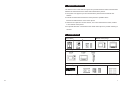
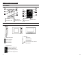
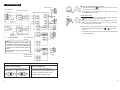
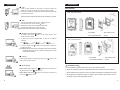
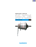
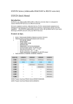
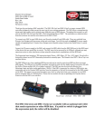
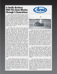
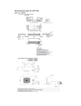
1 System Functions
The basic function of this Intercom system is to provide audio and video communication
between the external front door station and internal indoor phones.
Ɣ The system can support up to four internal indoor phones and two external door
stations.
Ɣ Internal communication between the indoor phones is possible via the
intercommunication button on the indoor phone.
Ɣ There are two options to connect the lock, one is from external door station, another
is from master indoor phone.
Ɣ An optional exit button can be fitted to the master indoor phone to provide unlocking of
the door.
2 Components
Door station
Master indoor phone
Accessories
Subsidiary(Abbreviated for “Sub. “) indoor phone
Other fittings
ƶPower supply
ƶ Indoor phone accessories
ƶ User manual
[Note] The power supply varies in different countries, please check with us before ordering.
12
1
3 Product Appearance
Door Station
1
5
6
2
4
6
3
3
6
5
1
6
7
4
2
1 Camera
2 Microphone
3 Speaker
5 Sensitive LED
6 White light LED
7 Name plate
4 Call button
Indoor Phone
ƿ Buttons
ƿ Status indicator
Power indicator
Busy indicator
Mute indicator
Talk button
Monitor button
Unlock button
Intercommunication button
Mute button
ƿ Adjustment
Brightness adjustment
Contrast adjustment
Ring volume adjustment
Talk volume adjustment
2
11
8 Trouble Shooting
4 System Diagram
Symptom
Ɣ The power indicator of indoor phone is
off after power up.
Ɣ Door station constantly beeps.
Ɣ The power indicator of Sub. Indoor
phone is on, but it doesn’t work.
Check the power supply wire connection.
Check the connection between the door station
and the master indoor phone.
1. Check the diode is wired correctly
2. Check if the connection between lock and door
station is correct.
Ɣ Door not unlocking.
9
Points to check
Specifications
Master Indoor Phone
Subsidiary Indoor Phone
Model
7010K/ 7130K
Model
7010P / 7130P/ 7H30P
Screen
Ǝ7)7Ǝ7)7
Screen
Ǝ7)7Ǝ7)7/ ü
Resolution
320*234 / 480*234
Resolution
320*234/ 480*234/ ü
Operating voltage
DC 24V
Operating voltage
DC 24V
Operating current
500mA
Operating current
350mA/ 350mA/ 100mA
Standby current
100mA
Standby current
100mA/ 100mA/ 40mA
Temperature
-10ć~+55ć
Temperature
-10ć~+55ć
Humidity
10ˁ~95ˁ
Humidity
10ˁ~95ˁ
Door Station
Model
7S40 / 7S60
Operating voltage
DC 14~18V
Operating current
300mA
Standby current
30mA
Temperature
-40ć~+70ć
Humidity
10ˁ~95ˁ
Camera
Color CCD, PAL system
Visible angle: 90°
Light source: White light LED
Min. Illumination: 0.1 Lux.
Wiring Recommendations:
1. Wiring distance between the front door station and the last indoor phone should be
less than 200m.
2. Single wire resistance between the front door station and the master indoor phone
should be less than 10ȍ.
3.
10
Recommended Cable is polyethylene Double insulated 1.2mm.
3
5 Wiring Diagram
Ƶ Intercom between indoor phone
Power supply
NC connection
Door station terminal
Master indoor phone terminal
Magnetic
lock
Magnetic
lock
Power
supply
Power supply
Electric lock
button on any of the indoor phones,
1. In standby mode, press
the other indoor phones will ring.
button on the ringing indoor phone to talk. Any other
2. Press
indoor phones will stop ringing.
Indoor phone 7H30:
1. In standby mode, pick up the handset of indoor phone, then press
button, the other indoor phones will ring.
2. Pick up the handset from one of the ringing indoor phone to
answer the call (If hands-free indoor phone: Press
button). Any
other indoor phones will stop ringing.
[Note] 1. There is no image during the intercom between indoor phones.
2. While ringing other indoor phones, press
Exit button
or
button to end
the call.
3. In intercom mode, if someone calls from door station, it will end this
intercom immediately.
Power
supply
Door station terminal
NO connection
Sub. indoor phone
terminal
[Note]
1. An optional exit button can be fitted to
the Master monitor to provide unlocking
of the door. (Just for the unlocking is
applied to the master indoor phone’s
lock).
2. Please wire the system as the diagram
one by one.
Last Sub. indoor
phone terminal
Power
supply
Power
supply
Switches on the back of the indoor phone.
Unlock time setting:
Video matching:
(Only for the MASTER indoor phone)
(Only for the Sub. indoor phone)
Unlock time: 1s
The last indoor phone’s switch should
Unlock time: 5s
be “ON”, and the other Sub. indoor
phones’ switch should be “OFF”.
4
9
7 Operation
6 Installation
Ƶ Call
1. When a visitor presses the call button on the door station, the
indoor phone rings, and the screen shows the visitor's image.
2. If there is no answer, the system will automatically reset to standby
mode after 30 seconds.
Door Station
Size: 140×100×43 mm
[Note]In two door stations system, if one of door stations is busy, the
other door station’s indicator will flash after the call button is pressed.
Ƶ Talk
1. Pick up the handset of indoor phone to answer the call.
(If hands -free indoor phone: Press button.)
2. While talking, hang up the handset to end the talk.
(If hands -free indoor phone: press button)
[Note] Conversation wills time out after 120 seconds.
Ƶ Monitor (For video indoor phone)
ķ Door/Wall
ĸ Door station front
1. In standby mode, press
button on the indoor phone to view
activity at the door station.
2. If there are two door stations fitted, to view at the different
entrances .
ĹDoor station Bracket
ĺ Screw
Press
button
Press
button
Door station 1
3. In monitor mode, press
to talk to the visitor.
Press
Door station 2
Size: 118×76×29 mm
button
End monitor
button on the indoor phone allows you
[Note] Monitoring the door station automatically ends after 30 seconds.
If someone calls from the door station, monitoring ends and the
indoor phone will chime.
Ƶ Unlock
Whilst ringing, talking or monitoring the door, press
indoor phone to open the door.
button on the
Indoor phone 7010: Adjust the
Adjustment to the lowest, the
indicator is on.
Indoor phone 7130: Press
is OFF, the
ĸ Door station front
ĹDoor station Bracket
ĺ Screw
Installation tips˖
Ƶ Mute setting
ring will turn off, and the
ķDoor/Wall
indicator is on.
button to mute ringing. When the ring
1. Don't install door station near humid, stove, and dusty condition.
2. There are waterproof silicone sheets attached to the reverse of the door station,
please install the door station to a smooth wall to guarantee the waterproof function.
3. We suggest the installation height of 1400mm. Also consider other factors such as
the angle of view and handicapped access.
8
5
Installation Tips
Indoor Phone
1. Don’t install the indoor phone in wet areas.
2. Keep away from direct heat.
3. Don’t clean the indoor phone with wet towels or harsh cleaning agents.
4. Do not disassemble the product. If failure occurs contact your service provider.
Bracket
Method 1
Method 2
Method 1
Method 2
6
7