1
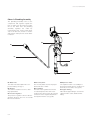
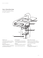
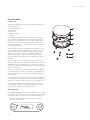
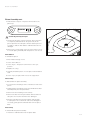
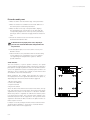
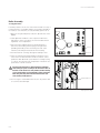
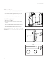
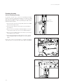
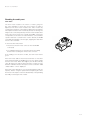
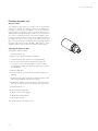
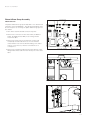
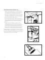
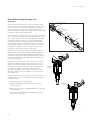
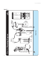
Clover 1s Technical Manual
This manual is intended for use by Certified Clover Technicians. Any use by
unauthorized personnel may void warranty, and constitute a safety hazard.
Please contact our service department with questions: 866.298.7203.
Rev A
Clover 1s Techincal Manual
CONTENTS:
Rev A
Symbols
4
Introduction
5
Site Requirements
6
First Time Startup
7
Subsequent Startups
10
Machine Views
11
Piston Assembly 17
Boiler Assembly
21
Plumbing Assembly
25
Platen & Brew Group Assembly
28
Outlet Assembly
33
Right-side Components
34
User Interface Information
37
Appendixes
43
Clover 1s Technical Manual
Symbols
Carefully read all text marked with the hazard symbols below
for your own safety and to avoid invalidation of the warranty.
The exclamation point within a triangle indicates a potential
for property damage, personal injury, or death. When visible on
hardware, this symbol alerts you to the presence of important
operating, servicing, or maintenance instructions in the
literature accompanying your Clover 1s.
The hot surface within a triangle alerts you to the presence of
a heated area that may be dangerous to the touch.
The lightning flash with arrowhead symbol alerts you to the
presence of uninsulated “dangerous voltage” within the Clover
1s enclosure that may be of sufficient magnitude to constitute a
risk of electric shock.
The exclamation point within a water droplet indicates that
hot water will dispense from the nozzle when the brew button
is depressed, constituting a burn hazard.
This manual also includes notes to expand your knowledge of
your machine.
The pencil symbol highlights information that will help you
make better use of your Clover 1s.
Information in this technical manual is subject to change without notice.
©2006 The Coffee Equipment Company
All rights reserved.
December 2006
P/N 010-0012-01
Rev A
Rev A
Clover 1s Technical Manual Introduction
The Clover 1s
The Clover 1s is the world’s first commercial single-cup
brewer built to meet the demands of today’s high-quality
coffee retailers. Clover 1s makes exceptional brewed coffee
by the cup in under a minute and opens up new possibilities
in a retail environment. The Clover 1s brews any coffee fresh
and exposes customers to an entire coffee menu. It creates a
higher-value coffee experience for brewed coffee. Single-origin
coffees can be featured easily and cost effectively.
The Clover 1s gives the barista unprecedented control in
achieving the desired result: a cup that repeatedly exhibits the
same qualities and subtle characteristics found in the roaster’s
cupping room. Our innovative technology borrows the best
of two time-honored brewing techniques: the press pot and
the vacuum pot. Like a press pot, Clover 1s mechanizes the
filtration process to control contact time independent of dose,
grind size, and filter density. And, like a vacuum pot, Clover 1s
filters using a vacuum, ensuring complete extraction and no
waste. Finally, Clover 1s uses PID (an advanced process control
technology) to maintain water temperature and a volumetric
sensor to accurately dose water
The heart of Clover 1s, the Vacuum-Press™ brew group, allows
rapid extraction while preserving the characteristics of your
most subtle coffees. PID thermal control and an intuitive user
interface allow the barista to control every aspect of the brew
process independently. Simply dose the coffee, grind, and
place the grounds in Clover’s brew chamber. Use Clover’s user
interface to adjust brew parameters (cup size, contact time,
etc.) and press “Brew”. Clover doses water, brews, filters, and
then dispenses. A quick wipe cleans off the permanent filter
and Clover is ready for the next cup.
We designed the Clover 1s for baristas in the busiest retail
environments, and built it to brew excellent coffee quickly. With
minimal training, a barista can dose, grind and brew a complete
beverage in just about a minute. The boiler heats water
immediately, and the intuitive digital user interface enables
rapid changes of brew parameters with every cup.
Rev A
Clover 1s Technical Manual
Site Requirements
Water
Water is a vital component to good coffee, hence water-quality
control is key. All installations will require some form of water
treatment. We are providing he following guidelines as a starting
point for acceptable water. However, due to the incredible
variability of water quality from region to region, a comprehensive
water specification is not possible. Generally, water must be free
of particulate and organic matter. Other basic parameters can be
tested using commonly available water test strips. Verify that the
water is free of chlorine. Note pH, alkalinity, and total hardness.
The following chart shows an acceptable range of total hardness
+ alkalinity for various levels of pH:
Dimensions
(inches)
&2/.4
3)$%
"!#+
B pH = 6.8: hardness + alkalinity = 190 - 500
B pH = 7.2: hardness + alkalinity = 120 - 300
B pH = 7.8: hardness + alkalinity = 90 - 175
Power
The Clover 1s requires 208-240VAC, single-phase, 20 amp
service. It is recommended that the service be a dedicated line.
Line voltage under load must lie within the specified range.
0/7%2
7!34%
7!4%2
7!34%0!33
4(25#54/54
&2/.4
Substances that may not show up through basic testing, but are
known to cause problems include, but are not limited to: silica,
barium sulfate, algae, chlorides, etc. When in doubt, the Coffee
Equipment Company can provide the names of labs that can
conduct more extensive water testing. The Coffee Equipment
Company does not take responsibility for any damage, loss of
use, or diminished performance resulting from water quality
problems.
Recommended
Installation
Footprint
2%!2
If the water does not test within this range, unexpected problems
with the water and coffee systems may occur and mineral build
up may result. It is our experience that water with total hardness
between 75 and 150 ppm will produce coffee with the most
pleasing flavor profile.
7!4%27!34%
0/7%2#54/54
If you fail to follow these guidelines, the result may be diminished
performance and machine malfunction. The Coffee Equipment
Company is not responsible for malfunctions, damage, loss of
use, or diminished performance resulting from power that is out
of specification.
Drain
You will need an external waste drain. The Clover 1s comes with
4.5 feet of 1 inch OD flexible hose. It is necessary that the hose
be routed such that gravity will allow waste water to flow down
to the appropriate drain.
Rev A
Clover 1s Technical Manual Clover 1s First Time Start-up Instructions
Failure to follow start-up instructions may result in damage to
the Clover which will not be covered under warranty. Be sure
to follow these instructions carefully.
Recommended Hardware:
B Stainless steel braided hose, with a 3/8F compression
fitting for the Clover. The Clover 1s is shipped with a 3/8
male compression fitting for the plumbing inlet.
B L6-30R, 250 VAC, 30 Ampere Receptacle; the Clover 1s is
shipped with a NEMA L6-30 plug.
B Tools: see the recommended tools list Appendix 1.
Installation
Water Connection
Connect the water supply to the machine water-inlet using
the stainless steel braided hose with a shut-off valve installed
between the water supply and the hose. The Clover’s water inlet
is located underneath the machine next to the right rear leg. The
water inlet is a 3/8” compression male fitting.
Water Supply Inlet, 3/8” Compression
Do not over tighten the fittings. The inlet is brass and can crack
or strip if over-tightened.
Drain Hose Connection
Connect the drain hose and route the hose so the hose is not
kinked and there is a downward slope. You connect the drain
hose underneath the machine just to the right of the left front
leg. Be sure to secure the drain hose to the Clover’s drain pipe
with the hose clamp using either a flat-head screwdriver or a
5/16” nut driver.
Grounds Chute/Bucket
Install the grounds chute or bin. If the Clover came with a passthrough chute, ensure the path is clear to the spent-grounds bin
under the counter.
Drain Hose Connection
Electrical Connection
Ensure you have the appropriate receptacle. The machine is sent
with an L6-30P to connect with an L6-30R
Electrical Connection L6-30P & L6-30R
Rev A
Clover 1s Technical Manual
First Time Start-up cont.
Main Power Switch
Flip the main power switch to the “on” position by pressing up.
The main power switch is located on the front panel, below and
to the right of the display.
On the initial start up of a Clover, the display will read:
Quickly push the rotary knob, located to the right of the display.
The display will then read:
Open the water supply and momentarily press the rotary knob.
The display will read:
The boiler will begin to fill until the air and water pressure in the
boiler equalize with the water supply.
After approximately two minutes, the Clover 1s will purge the
remaining air from the boiler. It will do this by opening the fill
valve allowing the pressurized air to escape through the nozzle.
When all the air has escaped, water will be dispensed into the
coffee chamber, from which it will be purged. To ensure the
boiler is completely full, the Clover will run three purge cycles.
The display will read:
AutoFill Cycle # 2 and AutoFill Cycle # 3 will automatically follow.
At the end of each purge cycle, the piston will move up and then
down to remove any water that may have been dispensed.
Rev A
Clover 1s Technical Manual First Time Start-up cont.
After filling in the third cycle, the Clover 1s display will read:
If no water has been dispensed into the coffee chamber, turn the
machine off and ensure your water supply is turned on, and that
there is sufficient pressure before restarting this sequence.
If water has dispensed properly, the Clover 1s boiler will begin
heating and the display will read:
After running a brief startup sequence, the Clover 1s will reach
the Brew Menu.
The boiler must always be filled when the machine is being
operated. The boiler does not need to be filled every time the
Clover is started; however, if the boiler is drained, the boiler
must be filled again prior to use. See Normal Operation on page
9 in the User Manual, revision “D”.
Once the Clover has run its startup sequence and begins to heat
up, it should come to temperature in less than five minutes.
Rev A
10 Clover 1s Technical Manual
Subsequent Startups
Each time the machine is turned on, the Clover 1s will display
the following prompt:
Once the First Time Startup procedure has been performed (see
above), the boiler will remain full until it is purposefully drained.
The boiler does not need to be filled every time the Clover 1s
is started. In most cases, the answer to this prompt will be
Yes .
The boiler must always be full when the machine is being
operated. If the boiler is drained (e.g., to move the machine), it
must be filled again prior to use or severe damage will occur.
If you are aware that the boiler has been drained, select No . If
the piston is not already at the bottom of the coffee chamber, it
will begin moving downward and the display will read:
Once the piston reaches the bottom of the coffee chamber, the
fill valve will open and the machine will display the prompt:
Wait until water begins to dispense from the nozzle and then
select “Yes” by pressing the rotary knob.
Do not leave Clover 1s unattended while this prompt is
displayed. Though it may take a minute or more to fill the
boiler, once it is full, water will dispense from the fill nozzle
until the user selects Yes .
Selecting Yes will close the fill valve, activate the boiler, and
begin the startup sequence. Once this process completes, the
Brew Menu will be displayed.
Rev A
Clover 1s Technical Manual 11
Clover 1s Front View
01
02
03
04
05
06
07
08
09
10
Power Switch
Rotary Knob
Nozzle
Brew Chamber
Grounds Chute
Brew Button
Display
Outlet
Drain Tray
Scraper
01 Power Switch
The power switch has two positions:
on and off. When you first turn on your
Clover 1s, follow the startup instructions
shown on the display. (See pg. 8.)
02 Rotary Knob
The rotary knob allows you to adjust
parameters by turning in both directions,
and to make a selection by pressing the
knob. Further menus can be entered or
exited by holding down the knob.
(see pg. 32)
03 Nozzle
The nozzle dispenses water into the
coffee chamber at the temperature indicated on the display. (See pg. 28)
Dispensed water is hot!
Rev A
04 Brew Chamber
The brew chamber incorporates both the
brew cylinder and the piston assembly.
(See pg. 17, 28)
05 Grounds Chute
The chute for spent grounds can be used
either as a pass-through or as a removable bucket. Grounds are scraped into
the chute after each brew cycle.
(See pg. 7)
06 Brew Button
The brew button activates the brew
cycle. A brew cycle can also be cancelled
during the steep by pressing the brew
button. The brew button also pauses
filtration and initiates the cleaning cycle.
(See pg. 31)
07 Display
The display shows the current menu
selection. All user information is given
through the display, with the addition of
audible cues. (See pg. 32)
08 Outlet
The outlet dispenses the brewed coffee.
(See pg. 33)
Dispensed coffee is hot!
09 Drain Tray
The drain tray drains excess liquid
directly into the waste line. A boiler and a
brew valve also empty into the drain tray;
please do not adjust either. (See pg. 7)
10 Scraper
The scraper is used to wipe spent coffee
grounds into the grounds chute.
12 Clover 1s Technical Manual
Clover 1s Left View
The side panels are attached to the
chassis with four screws each. Use
a #2 Phillips head screw driver to
remove the screws. Under one screw
for each powder coated part, there is
one star washer, in compliance with UL
requirements for electrical grounding of
all metal parts.
04
03
02
05
01
06
07
01 Front Panel
The front panel can only be removed
when the Platen is removed from the
Chassis. (See pg. 33)
02 Brew Bottom
The brew bottom is attached to the bottom of the Brew Chamber. The Outlet
Valve is attached to the Brew Bottom;
the piston rod runs through it.
(See pg. 19)
03 Heat Blanket
The heat blanket surrounds the brew
chamber, providing a set temperature to
ensure a stable brewing environment.
(See pg. 28)
04 Platen
The stainless steel Platen incorporates
the Nozzle and the entire Brew Group.
The Platen is removable from the
Chassis for maintenance. (See pg. 28)
06 Brew Chamber Motor
The motor drives the piston up and down
in the brew chamber. (See pg. 30)
07 Waste Outlet
The waste outlet allows for coffee/water
to exit the machine to the appropriate
drain. (See pg. 7)
05 Outlet Valve
The three-way outlet valve is an electromagnetic valve that controls the vacuum
and dispense elements of the brew
cycle. (See pg. 31)
Rev A
Clover 1s Technical Manual 13
Clover 1s Right View.
04
Risk of electric shock when dealing
with electronic components!
03
05
02
01
06
07
08
01 Solid State Relay (SSR)
The SSR controls the heating elements
in the boiler. When the SSR receives a
5 VDC signal from the PCBA it closes,
completing the circuit. When the circuit
is complete, the heating elements
energize, heating the water. (See pg. 35)
02 PC Board Assembly (PCBA)
The PCBA manages the computing and
interfaces with each of the mechanical
components. (See pg. 34)
03 Gecko Drive
The Gecko drive is the interface between
the PCBA and the motor.
(See pg. 35)
Rev A
04 Piston Assembly
The piston assembly sits on top of the
piston rod. Along with the outlet valve
and motor, the piston assembly is the
principal mechanical component responsible for vacuum creation. (See pg. 17)
05 Fuses
The fuses protect the PCBA against
damage due to overload. The lower fuse
protects from piston-motor electricalsystem problems.
06 Motor Transformer
The motor transformer adjusts the
incoming voltage to the appropriate
level for the Motor. (208VAC to 28VAC;
240VAC to 24VAC; 230VAC [Euro] to
36VAC). (See pg. 35)
07 Machine Badge
The machine badge displays relevant
regulatory information and the machine
serial number.
08 Power Cord
The power cord carries power from the
wall to the main power switch. The main
power switch, when “off” allows no
power into the machine. When the main
power switch is in the “on” position,
power is allowed through the switch and
to the wiring harness. (See pg. 6)
14 Clover 1s Technical Manual
Clover 1s Rear View
The rear panel is secured to the chassis
with four #2 Phillips head screws. The
rear panel mounting screws are only
accessible after removing the side
panels.
04
05
03
06
02
01
01 Boiler Drain Valve
The boiler drain valve opens the boiler,
allowing for it to be easily drained.
(See pg. 22)
Boiler water may be hot!
02 Boiler
The stainless steel boiler contains 108
ounces of water. It has two heating
elements (4500 Watts) in the 208 and
240VAC versions. (See pg. 21)
03 Resistive Thermal Detector (RTD)
The RTD measures the boiler
temperature and is an integral part of the
PID system. The RTD cable should only
be plugged into RTD 1 socket on the
PCBA. (See pg. 28)
04 Fill Valve
The fill valve dispenses water from the
boiler, through the nozzle via the nozzle
hose, into the brew chamber.
(See pg. 24)
05 Thermal Cut Off (TCO)
The TCO sets an upper limit for boiler
temperature, which, when reached, will
automatically cut power to the heating
elements.
06 Plumbing Assembly
See view on pg. 15.
Rev A
Clover 1s Technical Manual 15
Clover 1s Plumbing Assembly
The plumbing assembly refers to the
components that together regulate the
flow of water from the machine’s water
inlet to the boiler inlet. The plumbing
assembly regulates the water by
restricting the flow, ensures water flows
only in one direction, meters for volume
and releases water pressure as the boiler
is heated.
05
04
06
03
07
02
01
01 Water Inlet
The water inlet has a 3/8th male compression fitting. (See pg. 7)
04 One-way Valve
The one-way Valve ensures the proper
directional flow of water.
02 Strainer
The strainer contains a screen to catch
large particulates.
05 Flow Meter
The flow meter regulates the amount
of water dispensed. The flow meter
measures the water volume by counting
revolutions of the magnets attached to
the impeller within it. (see pg. 26)
03 Pressure Regulator
The pressure regulator ensures that the
upstream pressure does not exceed 40
PSI into the machine.
Rev A
06 Expansion Valve
The expansion valve is set to 60 psi. It
allows pressurized water to escape from
the boiler, as necessary. (See pg. 27)
07 Copper Tubing
Flare-fitted copper tubing is used for the
expansion-valve outlet and boiler-inlet
fitting.
16 Clover 1s Technical Manual
Clover 1s Platen & Brew Group
The platen & brew group are attached
and constitute a single unit mounted on
the chassis. (See pg. 28)
04
03
01
02
05
06
01 Brew Group
The brew group consists of the brew
motor, piston rod, piston, brew chamber
and associated parts. (See pg. 28)
(See pg. 28)
02 Limit Switch Bracket
The limit switch bracket can be adjusted
to change the height limit setting for the
piston assembly. (See pg. 19)
03 Heat Blanket
The heat blanket surrounds the brew
chamber, providing a set temperature to
ensure a stable brewing environment.
04 Platen
The stainless steel platen incorporates
the nozzle and cutouts for the user
interface, piston and grounds chute.
05 Brew Motor Assembly
The brew motor assembly consists of
the brew motor, motor frame, piston rod,
and limit switch bracket. It is removable
from the brew bottom/platen.
(See pg. 28)
06 Brew Motor
The brew motor is not a component
serviceable by the technician.
Rev A
Clover 1s Technical Manual 17
Piston Assembly
Components
The piston assembly is made up of the following components:
1.Umbrella valves,
2.Self- sealing screws
3.Piston base
4.Teflon seal
5. Elastomer seal
6.The filter
The umbrella valves are a type of one-way check valve. They
have a nub which holds them in place and acts as a plunger
limit. They mate along the bottom of the piston base; when
there is no vacuum to draw them away from the piston base
surface, they maintain a seal, allowing no liquid to escape the
well in the piston base.
The piston base is made from stainless steel. The bottom side
is a flat surface with a threaded hole in the center, where it is
fastened to the piston rod. The top interior has three wells;
at the bottom of each of these the umbrella valve’s ports
and mount holes are found. The center hole in each well is
the mounting hole, through which the umbrella valve stem is
installed.
The filter keeps the coffee grounds from entering the cup,
determines the clarity of cup and affects brew time. The factory
default filter mesh is a 70 micron filter. There are two other
mesh sizes of filters: the 40 micron (tighter mesh) and the 100
micron (looser mesh).
The filter is secured to the piston base by six 6-32 x ¼ Phillip
head self-sealing screws. These are easily recognizable by the
orange o-ring on the screw. The o-rings help prevent vacuum
loss and leaks.
The Teflon piston seal seals the piston on the cylinder walls. Do
not scratch the Teflon surface; do not use abrasive substances
or devices to clean the seal. It is best to use a clean bar towel.
The elastomer seal presses out on the Teflon seal to ensure it
is snug against the cylinder walls and provides a seat for the
filter so that grounds do not get under the filter.
Piston Removal
If anything is being done to the machine that will involve removing
the brew group, it is best to remove the piston before shutting
the machine off. (See pg. 36 for user interface information)
1. Enter the Basic Settings menu, find and select [Move
Piston? : +sub-menu+];
Rev A
06
05
04
03
02
01
18 Clover 1s Technical Manual
Piston Assembly cont.
2. Find and select <Eject>. The piston will rise above the
platen top.
Caution: the piston may be very hot.
O-RING
3. Gently turn the piston counter-clockwise. Once the piston
is completely unthreaded from the piston rod, lift the
piston up and set in a safe place. Ensure that the piston is
set aside so that the filter and the umbrella valves are not
damaged.
4. Remove the o-ring located on the top of the piston rod, set
it in a safe place, preferably with the piston so it is not lost.
Reinstallation
To reinstall the piston:
Piston Rod O-ring Location
1. Enter “Basic Settings” menu.
2. Select “Move Piston.”
3. Select “Eject.” The piston rod will move to the eject
position.
4. Replace the o-ring
5. Carefully thread the piston on to the piston rod’s threaded
stud.
6. Select “Top”; the piston will move to the top position.
Disassembly
To disassemble the piston assembly:
1. Loosen the 6 self-sealing screws on the bottom side of the
piston.
2. Lightly tap the self-sealing screws: this will break the filter
assembly away from the piston base.
3. Remove the 6 self-sealing screws entirely.
4. Remove the filter from the piston base and set aside in a
safe place. Do not allow the filter to be damaged.
5. Pull the seals away from the piston base and set aside
in a safe place. Do not allow the seals to be damaged. If
necessary, gently pull the umbrella valve from the piston
base.
Reassembly
To reassemble the piston assembly:
1. Insert the 3 umbrella valves into the piston base.
Rev A
Clover 1s Technical Manual 19
Piston Assembly cont.
2. Place the Teflon seal around the edge of the piston base.
3. Place the elastomer seal between the inside diameter of
the Teflon piston seal and the piston base.
4. Place the filter on the top of the piston base, aligning
the threaded inserts on the bottom of the filter with the
corresponding depressions on the top of the piston base,
pressing it down so that it fits snuggly inside the elastomer
seal.
5. Ensure the elastomer seal is level and not twisted or
buckled underneath the filter.
If the filter will not sit properly in the seals, it may help to
place the seals around the filter before setting the filter onto
the piston base.
6. Carefully flip the piston over. Lie it down on a soft, nonabrasive surface.
7. Fasten the filter to the piston base with the 6 self-sealing
screws. Tighten in a cross pattern. Do not over tighten:
over tightening will warp the filter: tighten to 10 inchpounds maximum.
Limit Switches
The limit switches, or piston position switches, are optical
sensors that are triggered when a flag on the piston rod actuator
plate passes through a light beam cast from an LED inside the
sensor. The light beam is read or sensed by a photosensitive cell
opposite it. These switches are normally closed switches and
are installed on the limit switch bracket.
04
03
When triggered, the voltage going through the switch is
interrupted, which in turn signals the CPU where the piston is,
depending upon which limit switch has been triggered.
1.Bottom Limit Switch
2.Limit Switch Bracket
3. Top Limit Switch
4. Eject Limit Switch
There are three limit switches: the bottom limit switch, the top
limit switch and the eject limit switch. The bottom limit switch
signals that the piston is at the bottom of the brew chamber.
When this position is signaled, the CPU knows that the piston
is at the bottom position. The top limit switch signals to the
CPU that the piston is at the top position. The eject limit switch
signals the CPU that the Piston is above the platen surface so
that it may be removed.
It may be necessary to adjust the limit switches after the brew
group has been repaired (i.e., the piston is not flush with the
platen surface when in the top position).
Rev A
02
01
Limit Switches & Limit Switch Bracket
20 Clover 1s Technical Manual
Piston Assembly cont.
Adjusting Limit Switches
To adjust the limit switches:
1. Remove left side panel.
2. Loosen the two 6-32 x ¼ PH screws that secure the limit
switch bracket to the motor frame.
3. Move the bracket up or down as necessary.
4. Test the accuracy using the Piston Move sub-menu in the
Basic Settings menu.
It is important that the ribbon cable for the limit switches
are plugged in when operating the Clover. If the cable is not
connected, the PCBA assumes that the piston is in the right
position. Note that when the ribbon cable is disconnected from
the PCBA that all the indicator LEDs are lit. Thus, if the piston
is in the top position when the ribbon cable is unplugged and
the machine is commanded to brew, the piston will not move
down. The machine, assuming that the piston is at the bottom
(the appropriate LED [D17] being lit along with all the others)
will dispense very hot water onto the piston which will be
flush with the platen surface.
Rev A
Clover 1s Technical Manual 21
Boiler Assembly
Cooling the Boiler
It is always easier to work on a coffee machine that is not hot; it
is safer and more comfortable. While it is not always possible or
necessary to cool the boiler, it is easy and fairly quick to do so.
1. Remove the right side panel; locate the dip switches on the
PCBA.
2. Slide dipswitch number 4 to the on position. When this
dip switch is in the on position, the Clover is able to brew
regardless of it’s temperature.
3. Disconnect the SSR DC input from the board [J12] or
disconnect the heating element plug to the right of the
plumbing assembly (on the left if facing the rear of the
machine). This will prevent the boiler from heating.
4. Turn the machine on and go through the startup screen.
5. Once the machine has initiated and is at the brew menu,
select a size of 16oz and a time of 10 seconds for coffee
production. Run about 10 cycles with these settings (using
no coffee). This will lower the temperature in the boiler to a
point where it can be touched.
DIP SWITCH 4
SSR CONNECTOR
DIP Switch & SSR Input
Ensure that the temperature is below 90 degrees Fahrenheit
after running ten cycles according to the instructions above. If
the boiler is still too hot to be safely handled, continue running
cycles until the boiler can be handled. Be cautious around the
boiler end plates; they retain more heat than the boiler side
walls and may still be quite hot.
6. Do not forget to return DIP Switch 4 to the off position and
to reconnect the SSR input.
HEATING ELEMENT PLUG
Heating Element Plug
Rev A
22 Clover 1s Technical Manual
Boiler Assembly cont.
Draining the Boiler
To drain the boiler:
1. Turn the machine off.
2. Disconnect the SSR DC input from the board [J12] or
disconnect the heating element plug to the right of the
plumbing assembly (on the left if facing the rear of the
machine). This will reduce the likelihood of mistakes later.
DRAIN VALVE
3. Connect a flexible 3/8 inch ID hose to the barbed fitting on
the drain found on the bottom of the boiler, and lead the
drain hose to a drain.
4. Close the main water supply.
5. Open the boiler’s drain. Note that no water will drain from
the boiler at this point.
6. Power the machine on. The machine will read:
Boiler Drain & Hose
FILL VALVE
RTD1
7. Select <No> and press the rotary knob. This will open the
fill valve, which will allow the water to drain from the boiler
freely.
8.Once the boiler is drained, power off the machine and
disconnect the machine from power.
Warning: if the machine is powered up, and the machine
activates the boiler heating elements when there is no water
in the boiler, severe damage may result.
9. Do not forget to close the boiler drain valve when finished.
Removing the Boiler
To remove the boiler:
Fill Valve & RTD1 Connections
1. Cool and drain the boiler (see above).
Warning: The boiler may be extremely hot.
2. Disconnect RTD 1/thermostat connector [J10] and the fill
valve connector [J1] from the PCBA and feed them through
the grommet ports.
3. Disconnect the boiler heater wiring harness plug from the
wiring receptacle located on the right inner bulkhead.
4. Disconnect the boiler inlet tube from the flare fitting at the
plumbing tee.
5. Disconnect the fill nozzle tube from the fill valve outlet.
Rev A
Clover 1s Technical Manual 23
Boiler Assembly cont.
6. Remove the four Phillips head screws (located on the left
side of the unit) that secure the boiler to the chassis.
7. Lift the boiler up slightly and pull the boiler out from the
back of the chassis, ensuring that the wiring harness does
not catch on the chassis.
Now the boiler may have any necessary repairs performed.
BOILER TO CHASSIS
MOUNT SCREWS
Removing the Heating Elements
To remove the heating elements:
1. Remove boiler (see above).
2. Disconnect the heating element wires from the heating
elements.
3. Use a 1.5 inch socket to remove the heating elements;
they are threaded normally (counter-clockwise to remove).
4. When installing heating elements, tighten to hand tight,
then with socket/breaker bar, tighten 1/3 turn more.
Boiler-to-Chassis Mount Screws
Reinstall the boiler in reverse order. Be sure to use a high
temperature cable tie to secure the fill nozzle tube to the fill
valve outlet.
Removing Heating Elements
ELEMENT
SPACER
ELEMENT GASKET
Heating Element Components
Rev A
24 Clover 1s Technical Manual
Boiler Assembly cont.
Fill Valve
The fill valve is located on top of the boiler: this valve, a two-way
valve, is used to dispense water from the boiler into the brew
chamber via the nozzle hose. Line pressure is used to push the
water from the boiler, through the fill valve and out the nozzle. It
consists of a solenoid and the valve.
NOZZLE HOSE
FILL VALVE
The solenoid is an electromagnet which is used to move the
plunger inside the valve. When the solenoid is energized, a
magnetic field is created, drawing the plunger away from the
valve seat and allowing water to flow through the valve.
The valve consists of three discrete pieces:
B The valve body and valve seat. This is where the water
flows in and out. The valve plunger rests on the valve seat
to close the flow of water.
B The valve stem: this piece screws into the valve body; the
valve plunger rests inside the valve stem. The solenoid
surrounds the valve stem.
Fill Valve Location
B The valve plunger and spring lie inside the valve stem; the
plunger rests on the valve seat to close the valve path.
If there is a constant leak from the nozzle that only disappears
when the water main is shut off, the fill valve’s plunger seal has
failed. This may be due to build up, sediment or to the failure of
the seal material. It is necessary to replace the fill-valve plunger.
MANIFOLD
O-RING
PLUNGER
Replacing the Fill Valve Plunger
To replace the fill valve:
1. Turn off the machine and disconnect from power.
2. Shut off the water.
3. Remove the side panels and the rear panel.
SPRING
STEM
WASHER
COIL
HOUSING
4. Remove the boiler from the chassis (see above).
5. Remove the nut that secures the solenoid to the valve.
NUT
6. Remove the solenoid and set aside.
7. Use the spanner wrench to remove the valve stem from
the valve body.
Fill Valve Assembly
8. Remove the old plunger and spring from the valve stem
and discard. Discard the valve seat o-ring.
9. Clean the valve body and the valve stem.
10. Install the new plunger and spring in the valve stem.
11. Install the new o-ring in the valve body.
12. Reinstall the valve stem to the valve body; tighten with
the spanner wrench.
13. Reinstall solenoid to valve.
Reinstall boiler (see above) and test for proper operation.
Rev A
Clover 1s Technical Manual 25
Plumbing Assembly
Removal of Plumbing Assembly
In general it is best not to remove the plumbing assembly;
remove it only if a component is broken or if there is a leak
that cannot be repaired while it is in place. It is necessary to
first remove the boiler, so that the plumbing assembly can be
maneuvered for removal:
FLARE NUT
COPPER TUBING
1. Disconnect the flow-meter wiring cable [J9] from the PCBA
and feed it through the port.
2. Disconnect the expansion valve tube from the Plumbing
assembly Tee.
3. Remove the nut securing the bulkhead adapter to the floor
of the chassis. Take care not to lose the bulkhead spacer.
4. Remove the two Phillips head screws that secure the flowmeter bracket to the chassis.
Disconnecting Expansion Valve from Plumbing Assembly
5. Now lift the plumbing assembly up and out of the chassis.
Lay the plumbing aside in a safe place: it is now ready for
repair.
Reverse the order of the steps above to reinstall the plumbing
outlet. Be sure to reconnect the flow meter cable to the PCBA.
BULKHEAD
Plumbing Assembly Bulkhead Nut
FLOW METER
BRACKET SCREWS
Flow Meter Bracket Screws
Rev A
26 Clover 1s Technical Manual
Plumbing Assembly cont.
Flow meter
The flow meter measures the volume of water going into
the coffee chamber to ensure the correct volume of water is
dispensed. The flow meter measures the water volume by
counting the revolutions of the magnets attached to the impeller,
which spins inside the flow meter body as water is flowing. The
magnets are counted as pulses by the flow meter field (the flow
meter top). These pulses are read by the PCBA; each pulse
corresponds to a set volume of water. When the correct number
of pulses has been counted for the volume desired, the PCBA
commands the Fill Valve to de-energize, stopping the water flow
into the coffee chamber.
To check the flow meter field:
1. Disconnect the flow meter connector from the PCBA
socket [J9]
2. Set a digital multi-meter to ohms and check the reading
between the red and green wires at the connector.
Flow Meter
If the reading is 2.2 kilo-ohms ± 10%, the flow meter field is
good.
If the flow meter cable is disconnected or broken or if the flow
meter field has failed, the PCBA will not receive pulse signals
from the flow meter. When this happens, the fill valve will stay
open, allowing more than the desired volume of water to enter
the brew chamber until the fill sequence times out and an “EØ6
– Water Failure” error is displayed.
If the flow meter field fails, it is recommended that the field, the
impellor, and the o-ring be replaced. Avoid replacing the entire
flow meter. This requires extensive disassembly of the plumbing
assembly, increasing the risk of leaks.
Rev A
Clover 1s Technical Manual 27
Plumbing Assembly cont.
Expansion Valve
The expansion valve allows an escape route for pressurized
water as it is heated. The expansion valve is set to 60 PSI. It is
necessary to remove the front panel to access the expansion
valve’s fitting. The expansion valve is set at the factory and is
subsequently Loctited. However, it may become necessary over
the course of a machine’s lifetime to reset the expansion valve.
It is best to have the boiler cold to set the expansion valve. If
the expansion valve is set too high, the fill valve will not open
due to excessive pressure holding the fill valve plunger against
the valve seat; this will result in an “E06 – Water Failure”. If the
expansion valve is set too low, the unit will not heat properly.
Adjusting the Expansion Valve
To adjust the expansion valve:
1. Turn the machine off.
2. Remove the side panels and the rear panel.
3. Locate the boiler drain and remove the barbed fitting.
4. Connect a pressure gauge to the ball valve fitting. It is
necessary to have a two-inch nipple to clear the chassis.
The fittings are ¼ NPT. Use a pressure gauge the measures
at least 80 PSI.
5. Open the ball valve.
6. Turn the machine on and follow the normal procedures for
start-up.
7. As the machine heats up, adjust the expansion valve until it
drips slowly at 60 PSI on the pressure gauge.
8. Twisting the expansion valve clockwise will increase the set
pressure; counter-clockwise will decrease the set pressure.
9. Turn the machine off.
10. Shut the drain’s ball valve.
11. Remove the pressure gauge.
12. Reinstall the barbed fitting.
13. Reinstall the panels.
The machine will now be ready for use.
Rev A
Expansion Valve
28 Clover 1s Technical Manual
Platen & Brew Group Assembly
Platen Removal
OUTLET VALVE
CYLINDER HEATER
CYLINDER RTD
The platen and the brew group are attached to one another and
cannot be removed individually. The side and rear panels must
be removed prior to removing the platen and brew group from
the chassis.
1. Turn off the machine and disconnect from power.
2. Remove the connectors for the outlet valve, the blanket
heater, the blanket heater RTD, motor wiring, and the
motor limit cable.
3. Remove the nozzle hose from the boiler. Cut the heat
resistant zip tie that holds the hose on to the fill valve
outlet. Pull the hose from the fill-valve fitting; some water
may run out of the hose, which is normal and is of no
consequence.
4. Remove the outlet brew tube from the brew bottom outlet
fitting and the waste tube from the waste port on the outlet
valve.
MOTOR LIMIT CABLE
MOTOR CABLE
Platen-related PCBA Connectors
NOZZLE HOSE
FILL VALVE
Fill Valve & Nozzle Hose
DISPENSE
DRAIN
Outlet-Valve Hose Connections
Rev A
Clover 1s Technical Manual 29
Platen & Brew Group Assembly cont.
5. Remove the six hex screws that secure the platen to the
chassis. Use a 5/16” Allen key to loosen the screws. Two
are located next to the front panel. The other four screws
are located one either side of the rear chassis pillars.
#10-32 SOCKET HEAD CAP SCREWS
3 PER SIDE
6. Lift the front of the platen up from the chassis. Use a block
(for example, a small 2X4” block) to hold the platen up and
remove the serial cable from the rear of the user interface.
If the unit serial number is 064 see pg. 31.
7. Lift the platen and brew group straight up until the brew
bottom clears the top of chassis. Slide the platen and brew
group assembly to the left out of the chassis. Ensure the
wiring harness for the brew group does not catch and
break.
8. Carefully set the assembly down: it can be set down
vertically, resting on the bottom of the brew motor. The
assembly will be top heavy, so only set the assembly in this
manner if there is little chance that the assembly will be
knocked over. The safer solution is to lay the assembly top
down on to a soft surface, resting on the nozzle. This will
make it easier to remove the brew group from the platen.
Platen Hex-nut Locations
Reinstall the platen to the chassis in the reverse of removal. It
may be necessary to shift the platen to line up the threaded
holes so the screws can be started. Be sure to reconnect the
nozzle hose to the fill valve, the outlet tube to the brew chamber
outlet, and the waste tube to the outlet valve.
Removing Platen & Brew Group from Chassis
Platen & Brew Group in Safe Resting
Rev A
30 Clover 1s Technical Manual
Platen & Brew Group Assembly cont.
Brew Group Removal
To remove the brew assembly from platen:
1. Remove the platen from the chassis to access the brew
group assembly.
MOTOR FRAME SCREWS
Ensure that the brew piston is removed prior to removing the
brew group from the platen. It is possible to remove the brew
group from the platen without first removing the piston, but this
procedure is more difficult and should be avoided (see steps
7-9 below for this procedure).
2. Lay the platen down on a soft surface, so that the
assembly is lying on the nozzle and the right edge of the
platen:
3. Remove the outlet valve from the brew bottom by
disconnecting the outlet valve cable from the PCBA [J2].
Remove the waste tube from the barbed fitting on the
bottom of the valve and then unscrew (counter clockwise)
the valve body from the brew bottom.
Motor-frame Screws Attaching to Platen
The outlet valve may be removed from the unit without
complete disassembly.
4. Supporting the motor, remove the four 10-32 x 1 ¾ Phillips
head screws that secure the motor frame to the brew
bottom manifold.
5. Gently pull the motor straight away from the brew bottom
manifold, taking care not to damage the self-loaded seals.
Set the motor assembly aside.
6. Remove the brew bottom manifold from the platen cylinder
by removing the four 10-32 x 1 Phillips head screws. Set
the brew bottom aside in a safe place. The brew bottom
manifold is easily damaged if dropped. Note the o-ring.
If the piston is in the coffee chamber
7. Remove all 8 screws that secure the motor and the brew
bottom to the brew cylinder.
8. Gently pull the motor and brew bottom from the cylinder.
Be sure to pull the assemblies straight away from the
cylinder.
Removing Outlet Valve from Brew Bottom
9. Once the motor assembly, brew bottom and piston are
removed, the piston can be removed from the piston
rod and set aside. The brew bottom may subsequently
be drawn off the piston rod. Reassembly may be
accomplished in the normal sequence.
Follow these steps in reverse order for re-installation.
Rev A
Clover 1s Technical Manual 31
Platen & Brew Group Assembly cont.
Outlet Valve
LARGE MANIFOLD O-RING
SMALL MANIFOLD O-RING
The outlet valve, like the fill valve, is a electromagnetic valve;
however, the outlet valve is a three way valve. First, the outlet
valve closes the exit from the brew chamber, creating the
vacuum needed for extraction. Second, this valve links the
brew chamber to the coffee outlet. Third, it allows excess liquid
to drain through the valve’s exhaust port.
MANIFOLD
PLUNGER
PLUNGER SPRING
STEM O-RING
STEM
HOUSING WASHER
At rest, the valve is closed to the outlet, i.e., when the solenoid
is not energized, the valve plunger rests against the valve seat.
This is due to the pressure from the spring that surrounds the
valve plunger inside the valve stem. There is subsequently
no path from the brew chamber, through the brew-manifold
valve-inlet ports, and through the valve. When the solenoid is
not energized, the valve is closed to the outlet; however, the
plunger allows a path from the outlet tube down the stem
through the valve exhaust and into the drain tray.
COIL
HOUSING
NUT
DISCHARGE
FITTING
When the solenoid is energized, the valve plunger is pulled
away from the valve seat by the magnetic field created by the
solenoid coil. This action creates a pathway from the brew
chamber, through the brew-manifold valve-inlet ports, through
the valve and then back up through the brew-manifold outlet
ports to the outlet tube.
While excess coffee from the brew process left in the outlet
tube will flow back through the valve exhaust, any coffee or
water left in the brew chamber would remain there until the
next brew cycle. For this reason, the Clover is programmed
to energize the valve at certain times after a brew cycle.
This allows the liquid to go through the valve and thus to be
discharged. This process is noticeable when the valve clicks
after a brew cycle.
The valve screws into the left underside of the brew bottom
manifold. There are two o-rings that seal the mating surface. To
reinstall the valve:
Outlet Valve Assembly
COFFEE FLOW
DISPENSE
SEALING SURFACE
WHEN CLOSED (OFF)
PLUNGER IS UP
SEALING SURFACE
WHEN OPEN (ON)
PLUNGER IS DOWN
WASTE
COFFEE FLOW
DISPENSE
1. Thread the valve into the brew bottom.
2. Tighten hand tight and then tighten ¼ turn more with
channel-lock pliers.
SEALING SURFACE
WHEN CLOSED (OFF)
PLUNGER IS UP
3. Route the valve cable to the PCBA and plug into socket [J2]
marked OUTLET.
4. Connect the discharge tube to the barbed SEALING
fitting
on the
SURFACE
WHEN OPEN (ON)
PLUNGER IS DOWN
bottom of the outlet valve.
WASTE FLOW
Rev A
32 Clover 1s Technical Manual
User Interface (UI)
The UI is the input for commands from the user to the PCBA
and, in turn, it displays information about the machine state back
to the user. The UI consists of three main components:
01
02
03
1. The brew button
2. The display
3. The rotary knob
The brew button activates the brew cycle. It also cancels the
brew cycle if pressed prior to extraction. Once extraction has
started, pressing the brew button will pause filtration. Pressing
and holding the brew button initiates the cleaning cycle.
User Interface
The display provides the user with information regarding the
machine’s settings and current state. The rotary knob turns
in both directions to change values and pushes to change
selections.
If the UI requires maintenance, the entire assembly must be
replaced. On serial numbers 064 forward, the UI is mounted
similarly to a car stereo face plate. To remove the UI:
1. Remove the rotary knob from the encoder and locate the
locking screw.
2. Twist the locking screw counter-clockwise 1 1/2 turns to
reset the locking mechanism.
3. Lift the right-side of the UI up.
4. Pull the left-side spring free of the platen.
5. Disconnect the UI ribbon cable.
Reinstall in reverse order; tighten the locking screw until the
lock engages securely.
Rev A
Clover 1s Technical Manual 33
Outlet Assembly
Front Panel & Outlet Assembly Removal
To remove front panel and outlet assemblies, the platen must be
removed. (See pg. 28.) To remove the front panel assembly:
1.Remove the four Phillips screws (two on each side) that
secure the front panel assembly to the chassis. One of
the screws has a star washer behind it for UL compliance
reasons.
OUTLET TUBE
FRONT
PANEL
SCREWS
2.On the early models (serial numbers 12-16) there is also
a nylok nut located behind the outlet manifold that will
require removal before front panel assembly can be
removed. On later models (serial number 017 forward), the
stud for this nut still exists, but is not used.
3.Once all fasteners have been removed, pull the front
panel assembly straight forward. Note that the outlet tube
is drawn through the upper most grommet on the left
side. The front panel and the outlet manifold may now be
repaired and the main power switch, expansion valve and
outlet valve discharge are accessible.
4.Reinstall in reverse order; ensure the outlet tube is fed
through the grommet hole on the left side.
Outlet
Front Panel Screws & Outlet Tube
The outlet is what guides the coffee from the brew chamber
into the cup without making an unnecessary mess. The outlet is
comprised of two sub-assemblies: the manifold and the nozzle.
Outlet Manifold
The outlet manifold is attached to the splash guard with four 6-32
nylok nuts. The coffee enters the manifold from the fitting on top
and is distributed by the pressure from the brew chamber and
by gravity to the outlet nozzle. There is an o-ring to seal the gap
between the two components; this o-ring should be replaced
every 6 months. It is best to use a bit of food-grade lube on the
o-ring when the outlet nozzle is removed from the manifold, as
this will ease installation and removal.
Outlet Nozzle
The outlet nozzle consists of two main components: the outlet
and the deflector/vent assembly. The deflector ensures that
the coffee dispenses gently. The vent ensures that the coffee
is not restricted in its path: if the coffee finds restriction in the
outlet, it will create back pressure into the coffee chamber. The
deflector is sandwiched between two standoffs, with an o-ring
at the bottom to seal the vent port. The outlet nozzle should be
cleaned periodically, depending on usage.
/UTLET-ANIFOLD
Outlet Manifold & Nozzle
/UTLET.OZZLE
Rev A
34 Clover 1s Technical Manual
Right-side Components
PC Board Assembly (PCBA)
The use of an anti-static/grounding device is recommended for
any work done with electronic components.
The PCBA contains the computing and electronic controls of the
machine. To remove the PCBA:
1. Turn off the machine and disconnect from power.
2. Remove the right side panel.
3. Disconnect all cable terminals from the PCBA sockets.
4. Remove the four 6-32 x ¼ Phillips head screws that attach
the PCBA to the chassis.
5. After removing all the fasteners, gently pry the PCBA from
the two snap standoffs. Ensure that the board is safe from
moisture, dust, static discharge and other damage.
To reinstall the PCBA, follow the steps above in reverse order.
Software
The machine’s software is contained on the CPU chip. The
software is updated by replacing the CPU chip:
PCBA SCEWS
PCBA Screw Locations
1. Turn off the machine and disconnect from power.
2. Remove the right-side panel.
3. Locate the PCBA and the micro-controller in the upper, right
quadrant of the PCBA. The designation “U6” is directly left
of the micro-controller receptacle.
4. Insert the chip puller’s (part number CEC-9015) mandibles
into the slots on the lower left and upper right corners of
the micro-controller receptacle.
5. Gently squeeze the chip puller. The micro-controller will
come away from the receptacle.
6. Take the new micro controller and insert it into the microcontroller receptacle; ensure that the notch on the micro
controller is aligned with the indent in the receptacle.
7. Push the micro controller directly and gently into the
receptacle.
8. Replace the right side panel on to the Clover.
9. Plug the machine in and turn on. The unit will beep for
5 seconds after being turned on. This is entirely normal.
Proceed with normal start-up.
Rev A
Clover 1s Technical Manual 35
Right-side Components cont.
Motor Transformer
The Motor Transformer steps power down for use by the motor.
Each power configuration will have a specific transformer. To
remove the motor transformer:
1. Remove the platen (see pg. 28). (Without removing the
platen it is very difficult to access the inboard fastener and
to remove the transformer from the unit.)
2. Disconnect the motor transformer cable from the PCBA
[socket J16].
3. Remove the transformer; it is attached to the chassis floor
by two 10-32 x ¼ Phillips screws. (If the platen and brew
group assembly is in place, it is recommend that a flexible
bit drive is used to remove the inside screw.)
TRANSFORMER
SCREW LOCATIONS
Solid State Relay (SSR)
The SSR is an electronic switch that follows commands from
the PCBA to control the boiler heating elements. To remove the
SSR:
Motor Transformer & Screw Location
1. Turn off the machine and disconnect from power.
2. Remove the right-side panel.
3. Remove the SSR and heat sink, attached to the chassis
with two 10-32 x 1 ¾ Phillips head screws. (It is easiest to
use a stubby screwdriver; remove the top fastener and only
loosen the lower fastener.)
4. Remove the cables from the SSR. (Note that the VDC
signal wires are colored; the red always goes to positive,
A1, and the black to the negative, A2, on the SSR.)
SSR, Wiring & Heat Sink
Motor Driver
The motor driver (Gecko Drive) translates commands from the
PCBA for the motor. To remove the motor driver:
1. Turn off the machine and disconnect from power.
MOTOR DRIVER
(GECKO DRIVE)
2. Remove the right side panel.
3. Remove the motor driver, attached to the chassis with two
6-32 x ¼ Phillips head screws. (The motor driver is located
above and to the right of the PCBA.)
4. Carefully remove the motor driver wiring harness: do not
mix up the terminal sequence. Note that there is a ground
wire from the motor driver power ground terminal to the
chassis.
To re-install, reverse the sequences above.
Motor Driver (Gecko Drive)
Rev A
36 Clover 1s Technical Manual
Right-side Components cont.
Electrical Components
Following is an explanation of the Clover 1s electrical system:
1.The Power Cord carries power from the wall to the Main
Power Switch. The main power switch, when “off” allows
no power into the machine. When the main power switch
is in the “on” position, power is allowed through the switch
and to the wiring harness.
2.The wiring harness carries power from the switch to:
a. The PCBA
b. The heating elements through the solid state relay
3.The PCBA, in turn, carries power to the majority of the
machine’s electromechanical components:
a. The motor transformer*
b. The motor driver (Gecko Drive)
c. The fill and outlet valves
d. The RTD
e. The heat blanket
*The motor transformer steps the wall voltage from 208240VAC down to 28VAC for the brew motor.
4.The solid state relay receives a 5 VDC signal from the
PCBA. When the SSR receives this signal from the PCBA, it
closes completing the circuit from the switch to the heating
elements. When the circuit is complete, the heating
elements in the boiler will be energized, causing the water
to heat.
5. The heating elements draw 4,500 watts. They should never
be activated without the boiler being filled.
DIP Switch settings
DIP switches are used to override normal operation. The
following four DIP switches are used:
#1 “yes, skip startup” option (ON: enabled, OFF: disabled)
#2 If ON: entering tech settings sets next startup to
“FillBoiler” not “Is Filled?” *
#3 brew cylinder overtemp error (ON: disabled, OFF: enabled)
#4 OFF: normal operation, ON: disables waiting for hot water
during brew
* DIP Switches 5-8 not used at this time.
Rev A
Clover 1s Technical Manual 37
User-interface Information
Menus
This is where you will learn to adjust all of the Clover 1s brew
parameters and machine settings. The user interface is easy
to manipulate during normal use, and can also be used for
maintenance and troubleshooting. There are three menu levels
available to the Clover 1s user: Brew Menu, Basic Settings, and
Advanced Settings.
Key to Settings Menus
It will be helpful to understand these basic keys to the
Clover 1s display:
B “ ”: These carets appear within the display around text
or numbers, and denote that a selection with the rotary
knob is possible. Press the rotary knob to move the carets
(change between parameters). Turn the rotary knob to
change values within the carets.
B “+sub-menu+”: This text signals that a sub-menu is
accessible from the current parameter by pressing the
rotary knob.
B “*”: The asterisk, found in front of a value, denotes that
the displayed value is not a default. A default value will not
have an asterisk.
Brew Menu
The Brew Menu is what appears on the display when you are
about to make your Clover coffee:
The Brew Menu has two adjustable items: the drink SIZE
(Rinse; 6 to 16 ounces in 2-ounce increments), the brew TIME
(10 to 300 seconds), and one reading: the current brew-water
temperature.
To make changes to brew parameters within the Brew Menu,
note whether the “ ” surround the drink size or the brew
time. Switch between the parameters by pressing and releasing
the rotary knob. Change the setting by turning the rotary knob.
Once you have set the parameter values (the example here
shows 12oz and 40s, which is a 12-ounce drink with a 40second brew time), press the brew button, drop in the ground
coffee, stir, and watch the Clover 1s magic happen.
To run a clean cycle, press and hold the brew button. The
display will prompt: [Clean Cycle Start ]. Select Start . (See
page 15.) Cancel the clean cycle before it starts by selecting
Cancel and pressing the rotary knob, or just wait; the clean
cycle prompt will time out and return to the Brew Menu.
Rev A
38 Clover 1s Technical Manual
User-interface Information cont.
A screensaver will appear if the user interface is not used for
a period of time. The screensaver will display the model name
and a clock. To exit the screensaver mode, simply turn or press
the rotary knob or press the brew button.
Basic Settings Menu
To enter the Basic Settings Menu from the Brew Menu, press
and hold the rotary knob until [Boiler Set point] is displayed. To
exit a settings menu at any time, press and hold the rotary knob.
The Basic Settings Menu allows the Clover 1s operator to
adjust the brew-water temperature, move the piston, and
change workflow settings. Turn the rotary knob to move
between menu options.
1. Boiler Set point: This parameter displays the current
temperature in the lower left-hand corner of the screen
and the target temperature in the lower right-hand corner
of the screen. The temperature range is 180° Fahrenheit
to 210° Fahrenheit, adjustable in one-degree increments.
To change the target temperature, press the rotary knob,
which will shift the “ ” from the parameter selection
(TEMP) to the temperature value. Twist the rotary knob to
increase or decrease the value. Press the rotary knob to
select the desired target temperature value. If the target
value was increased, the temperature will begin to increase
immediately. If the value was decreased, the heaters will
not be switched on until the temperature falls below the
target value.
2. Wipe Workflow: This parameter allows the Clover 1s user
to select whether the machine will dispense the drink,
then allow the spent coffee puck to be scraped into the
spent grounds chute ( Wipe After ), or if the machine
will brew the coffee, but not dispense until the spent
grounds are scraped away ( Wipe Before ). For busy cafe
environments, the Wipe Before workflow is best. For
slower environments, the Wipe After workflow maintains
coffee chamber temperature and brew consistency best.
3. Move Piston?: This parameter leads to a sub-menu where
the Clover 1s user can move the piston. Press the rotary
knob to enter the Piston Move sub-menu. (To exit submenus, press and hold the rotary knob.) There are five
actions that can be taken in this menu. View actions by
turning the rotary knob, then select an action by pressing
the rotary knob.
a. To Jog: This action moves the piston up or down by turning
the rotary knob. Turning the rotary knob clockwise will
move the piston up; turning counter-clockwise will move
the piston down. Use this action to reinstall the piston
after ejecting it. Press the rotary knob to toggle back to the
Piston Move options.
b. Top: This action will move the piston to the top position
in the coffee chamber, where the piston is flush with the
platen.
Rev A
Clover 1s Technical Manual 39
User-interface Information cont.
c. Bottom: This action moves the piston to the bottom
position in the coffee chamber.
d. Eject: This action moves the piston out of the coffee chamber
for piston removal. Unscrew the piston counter-clockwise
to remove. After servicing and reinstalling the piston, select
Top to return the piston to its flush position.
e. Exit: This action will exit the user from the Piston Move
sub-menu.
4. Advanced Settings: This parameter allows the user to enter
the Advanced Settings Menu by pressing the rotary knob.
(See Advanced Settings Menu.)
5. Exit Settings: This parameter allows the user to exit the
Basic Settings Menu by pressing the rotary knob.
Advanced Settings Menu
The Advanced Settings Menu gives you further customization
options and control to create the perfect cup of coffee, as well
as the ability to track use and error codes.
Enter the Advanced Settings Menu by pressing the rotary knob.
Exit at any time by pressing and holding the rotary knob.
1. Machine Units: This parameter allows the Clover 1s
operator to view drink sizes and brew water temperatures
in metric terms: centiliters and degrees Celsius. Press the
rotary knob, then select English (F,oz) or Internat’l (C,cL)
by turning and then pressing the rotary knob.
2. Wipe Alert Beeper: This controls whether the Clover 1s will
remind the user to wipe spent grounds from the filter.
3. Screensaver Start: This parameter allows the barista to
turn the screensaver on or off, and select how much time
elapses before the screensaver starts. Dial the time down
to zero to turn the screensaver off. The factory default is 8
minutes. When active, the screensaver displays CLOVER
Coffee and the current time.
4. Cylinder Set point: This sets the temperature for the heat
blanket that is wrapped around the coffee chamber to
maintain heat. The temperature is adjustable from 130° to
180° Fahrenheit in 5-degree increments. The factory default
is 175° F.
5. Next Cup Settings: This parameter contains the settings
for what drink size and brew time will display automatically
after startup and after each drink. Press the rotary knob to
enter.
a. Next Cup Defaults: This setting allows you to decide
whether the Clover 1s will remain at the drink settings seen
on the Brew Menu display after each coffee production:
Last Cup ; or if the drink settings will revert to the
defaults after each coffee production: Default .
Rev A
40 Clover 1s Technical Manual
User-interface Information cont.
b. Default Size: This setting allows the Clover operator to
choose which drink size will appear when the machine
powers on and after each coffee production if Default
is selected in the Next Cup Defaults setting. The factory
default is 12 ounces.
c. Default Brew Time: The Clover 1s operator can change
the default brew time. The Clover will default to this time
when it is powered on or after each coffee production if
Default is selected in the Next Cup Defaults setting. The
factory default is 35 seconds.
d. Exit Next Cup: Up One Level: Selecting this feature will
return you to the Advanced Settings Menu.
6. Set Clock: These settings change the time and date for the
CPU clock. Not only is the screen saver clock based on this
data, but more importantly, it records the date and time
of all logged errors, which can be helpful for the service
provider. The factory default will be the current date and
the current time for the Pacific time zone. All dates are
shown in U.S. format: mm/dd/yy.
a. The top line of the display will show the new date and time
to be programmed into the Clover 1s.
b. Month: This is the first setting that will be selected. Make
adjustments by turning the rotary knob and confirm by
pressing and releasing it.
c. Day: Change the day of the month in the same manner as
the Month setting: values from 01 to 31 may be selected.
Please remember that February has 28 days, except in leap
years.
d. Year: Adjustments to the year can be set from 2006 to
2021.
e. Time: The hours and minutes of the clock setting may also
be adjusted. After these settings are entered, the Clover 1s
will ask: Done . Press and release the rotary knob to exit
the clock. Select Cancel to exit the clock settings without
saving any changes.
Rev A
Clover 1s Technical Manual 41
User-interface Information cont.
Technician Settings
These settings are accessed by pressing and holding the brew
button while in the advanced settings. A password is required.
Currently that password is: DCAB.
The following are the Tech Settings:
1. [Temp Offsets : +sub-menu+]
i. <Boiler 1 Offset> 0F
ii. <Boiler 2 Offset> 0F
iii.<Cylinder Offset> 0F
iv.<Exit Temp Offsets>: Up One Level
2.[PID Parameters : +sub-menu+]
i. BoilerPID – P: 0.60
ii. BoilerPID – I: 0.25
iii.BoilerPID – D: 2.0
iv.BoilerPID – I Max: 2.5
v. BoilerPID – I Min: 0.0
vi.Exit PID Params: Up One Level
3. [Absorption : <5.5%>]
4.[Max Speed: 600]
5. [Plumbing Loss : <0.75 oz>]
6. [Fill Rate: 166]
7. [Boiler Timeout: 480s]
8. [Cal Filter Moves: +sub-menu+]
9. [Cal Dispense Moves: +sub-menu+]
10. [Reset Service Log?: +sub-menu+]
i. Are You Sure? “command prompt window”
ii. <Yes> the service log and the error log are cleared. The
unit will display: Service Logs Cleared and then return to
[Reset Service Log?: +sub-menu+].
iii.<Cancel> the service logs will not be reset, unit will return
to [Reset Service Log?: +sub-menu+].
11. [Drain Boiler?]
12. [Exit Tech Settings: Up One Level]
Rev A
42 Clover 1s Technical Manual
User-interface Information cont.
Error Codes
When an error code occurs, it will be shown on the display. It
is also stored in the “Error Log” in the “Advanced Settings”
menu, see below. Error codes EØ1-EØ7 are all fatal, and will
require you to power cycle the machine. Error code EØ8 is a
warning, and does not require the machine to be turned off.
Machine States & Sub-States
The Error Log contains the date, time and a set of numbers
representing the machine’s state and sub-state at the moment
the error occurred. This log provides valuable information to
the technician for troubleshooting purposes.
For example, if an “EØ1-Piston Failure” error were to occur,
one would see the date and time of the failure, as well as the
following: “01/04.” These numbers represent a possible State
(01) and Sub-state (04). State 01 indicates the machine was
somewhere in the process of brewing. Sub-state 04 indicates
that the piston was in a downward motion at the moment the
error occurred. For a full listing of the States and Sub-states see
Appendixes 6-8.
Rev A
Clover 1s Technical Manual 43
Appendix 1
Suggested Tool List
B #2 PH screwdriver
B Electrical tape
B #2 PH screwdriver, stubby
B 1/4” socket wrench set, standard (w/ratchet, driver and
extension; deep socket would be helpful as well)
B #1 PH screwdriver
B 3mm flathead screwdriver
B 5/8” combo wrench
B Hex (Allen head) wrench set, standard (especially the
5/32”)
B 9/16” combo wrench
B 1-1/2” socket and ratchet (for heating elements; this refers
to socket, not the driver)
B ½” combo wrench
B Small file
B 7/16” combo wrench
B Fine grade emery cloth
B 3/8” combo wrench
B Pipe cutter
B 5/16” combo wrench
B Flare tool
B 8 inch adjustable wrench
B Pipe bend tool
B 6 inch adjustable wrench
B Level
B 9/16” flare nut wrench
B Food-grade lubrication
B Pliers
B Scotch-brite
B Needle nose pliers
B Mechanix gloves (thermal protection)
B Diagonal cutters
B Lint free cloth
B Vise grips (or equivalent)
B Snap ring pliers, internal and external
B Pliers, arc joint
B Thermometer, preferably digital
B Wire stripper (wire size 22-10)
B Digital multi-meter: one that reads ohms up to 5 kilo-ohms;
volts to 600 VAC/60 VDC; it would also be helpful if it came
with an amp clamp for reading VAC amps.
B Wire connector crimper
B Flashlight
B Small mirror
B Service cart
B Dental pick set
B Heated ultrasonic cleaner (optional, but very helpful for
cleaning parts up)
B Teflon tape (1/2 and ¼ widths)
B Peter Paul spanner wrench
Rev A
44 Clover 1s Technical Manual
Appendix 2
0OWER5PTHE#LOVER
3EEMANUALFORINSTALLINSTRUCTIONS
5NLESS#LOVERWASMOVEDOR
JUSTINSTALLEDANSWERh9ESv
WHENASKEDh)S"OILER&ILLEDv
Quick Start Guide
'RIND#OFFEE&RESH
-EASURETHECOFFEEANDGRIND
$IAL"REW3ETTINGS
#HOOSETHEDRINKSIZEANDSTEEPTIME
4RYDOSINGG
FORAOZDRINK
4URNKNOBTOCHANGEVALUE
0USHKNOBTOCHANGESELECTION
!PAPERFILTERGRINDSIZE
ISAGOODSTARTINGPOINT
3ELECTIONINDICATEDBY
"EGIN"REW#YCLE
1UICKLYPRESSTHEh"REWvBUTTON
!DD#OFFEE'ROUNDS
0OURGROUNDSINTOTHECOFFEECHAMBER
!CCIDENTALLYHOLDINGTHEh"REWv
BUTTONWILLRAISEACLEANINGCYCLE
PROMPT5SETHEKNOBTOCANCEL
7IPE!WAY'ROUNDS
&IRSTUSETHEWIPERTHENABARTOWEL
3TIR#OFFEE'ROUNDS
%NSURECOMPLETEWETTINGOFGROUNDS
0OURINTHEGROUNDSASTHEPISTON
DROPS4HEPISTONMAYPAUSETO
PURGETHEBREWGROUP
#
"EGINA#LEANING#YCLE
#LEANATLEASTONCEEACHDAY
(OLDTHEh"REWvBUTTONAND
THENSELECTh3TARTvTOBEGIN
4RYRINSINGBETWEENDRINKS$IAL
THEBREWSIZEDOWNTOh2INSEv
ANDPRESSSTHEh"REWvBUTTON
5SEABARTOWELTOWIPETHE
FILTERWHENPROMPTEDh7IPE
&ILTERvTHENSELECTh/+v
5SEANONABRASIVESTIRRER
#
3TIRINA#LOVER#LEANING4ABLET
7AIT^MINFORCYCLETOCOMPLETE
!TTHEh3TIR)N#LEANERv
PROMPTSTIRINACLEANING
TABLETANDSELECTh/+v
"REWASEASONINGCOFFEE
BEFORESERVINGCUSTOMERS
Rev A
Rev A
%6
%4
&-
3
0LUMBING
)NLET
02
"6
(%
"OILER
(%
&6
.OZZLE
-OTOR
#6
"REW
'ROUP
&
6
7ASTE4RAY
DRAINSWHEN
MANUALVALVE
ISOPEN
"(
#LOVERS\0LUMBING$IAGRAM
UT
R V I N G S PO
T O
SE
#%#
$ISPENSE
.OZZLE
#/&&%%
(/4
#/,$
%XTERNAL&LOW+EY
#/&&%%
(/4
#/,$
)NTERNAL&LOW+EY
3TRAINER
0RESSURE2EGULATOR
&LOWMETER
%XPANSION4UBING
%XPANSION6ALVE
(EATING%LEMENTS
"ALL6ALVE
&ILL6ALVE
"LANKET(EATER
&ILTER
#HECKVALVE
7AY6ALVE
#OMPONENT+EY
3
02
&-
%4
%6
(%
"6
&6
"(
&
#6
6
Clover 1s Technical Manual 45
Appendix 3
OVERFLOWSPILLS
6
,
2OCKER3WITCH
%NCODER
!CTUATOR
-OTOR
4RANSFORMER
"REW,IMITS
/UTLET
6ALVE
"LANKET(EATER
2%$
"REW'ROUP
7()4%
5SER)NTERFACE
,%$
-OTOR$RIVER
332
0OWER'ROUND
TO6$#
0HASE!
0HASE"
0HASE#
0HASE$
$ISABLE
$IRECTION
3TEP
#OMMON
#URRENT3ET
#URRENT3ET
#LOVERS\7IRING$IAGRAM
#%#
WHITE
RED
RED
&LOWMETER
0LUMBING
)NLET
WHITE
RED
RED
(EATING
%LEMENT
24$
&ILL
6ALVE
(EATING
%LEMENT
4#/
"OILER!SSEMBLY
46 Clover 1s Technical Manual
Appendix 4
Rev A
IRES
EW
WHIT
"REW'ROUP
"OILER!SSEMBLY
0LUMBING)NLET
5SER)NTERFACE
!SSEMBLY,EGEND
BLAC
KWI
RES
-OTOR&USE
XMM6!SLOWBLOW
6FROM
0OWER3WITCH
S
5SER)NTERFACE
BLACKWIRE
2ELAY&USE
XMM6!SLOWBLOW
4RANSFORMER
*UMPERREQUIRED
IRE
3ERIAL0ORT
CHASSISPASSTHRU
REDGREEN
"REW,IMITS
WHITEWIRES
&ILL6ALVE
W
CK
IRES
REDW
"LANKET(EATER
C KWIRE
S
B
LA
/UTLET6ALVE
#LOVERS\"OARD#ONNECTIONS
BLA
B LA
S
ES
CK
WIRE
WIR
BOW
RAIN
B
CKW
24$
A
BL
IRE
&LOWMETER
RE
DW
I RE
BL
AC
K
W
IR E
332)NPUT
!CTUATOR-OTOR
'ECKODRIVE
CK
WIR
ES
BLA
Rev A
LAC
KW
#%#
IRE
Clover 1s Technical Manual 47
Appendix 5
IRES
E W
WHIT
48 Clover 1s Technical Manual
Appendix 6
Machine States (software version)
The Error Log contains the date, time and a set of numbers representing the machine’s state and sub-state at the moment the
error occurred. This log provides valuable information to the technician for troubleshooting purposes. For example, if an “EØ1Piston Failure” error were to occur, one would see the date and time of the failure, as well as the following: “01/04.” These
numbers represent a possible State (01) and Sub-state (04). State 01 indicates the machine was somewhere in the process of
brewing. Sub-state 04 indicates that the piston was in a downward motion at the moment the error occurred.
State
098
Idle Menu
0
Brew
1
Basic Settings
2
Filter Move Settings
3
Dispense Move Settings
4
Next Cup Settings
5
Counters (in Settings)
6
Beeper Settings
PID Parameter Settings
7
Advanced Settings
8
Temp Probe Offset Settings
9
Tech Settings
10
Startup Sequence (purges water in brew group)
11
Piston Move Mode (in Settings)
12
Confirm Action
13
Piston Moving
14
Error
15
Dispensing Water (not used during brewing)
16
Enter Tech Settings Password
17
Status Message
18
Setting Clock
19
Viewing Error Log
20
Clean: Initial rinse
21
Clean: Waiting for barista wipe
22
Clean: Filling for soak cycle
23
Clean: Waiting for barista to insert cleaner
24
Clean: Soaking
25
Clean: Soak cycle dispense
26
Clean: Wash cycles (3)
27
Clean: Complete
28
Confirm Start Clean
29
Boiler Heater Timed Out Message
30
Boiler Fill
31
Drain Boiler
32
Display “Is Boiler Filled?” question (normal startup screen)
Display “Welcome To Clover” message (initial startup screen)
092
0
1
2
3
4
5
6
7
8
9
10
11
12
13
14
15
16
20
21
22
23
24
25
26
27
28
29
30
31
32
33
34
17
18
19
Rev A
Clover 1s Technical Manual 49
Appendix 7
Machine Sub-States: Brew & Clean
The Error Log contains the date, time and a set of numbers representing the machine’s state and sub-state at the moment the
error occurred. This log provides valuable information to the technician for troubleshooting purposes. For example, if an “EØ1Piston Failure” error were to occur, one would see the date and time of the failure, as well as the following: “01/04.” These
numbers represent a possible State (01) and Sub-state (04). State 01 indicates the machine was somewhere in the process of
brewing. Sub-state 04 indicates that the piston was in a downward motion at the moment the error occurred.
All
Brew Sub-State Description
Versions
Determine whether or not to bypass brew cylinder purge 0
Wait for piston move down to valve pulsing position 1
Pulse valves to remove waste from brew cylinder 2
Set valve state and start piston move down to bottom of brew cylinder 3
Wait for motor move down to bottom of brew cylinder
4
Wait for water to reach brew temperature (if not there already)
5
Pause before dispensing hot water, display burn hazard warning
6
Setup hot water dispense
7
Wait for flow meter to reach target volume
8
Wait for brew timer to elapse 9
Wait for brew button press (only used if initial filtration is paused)
10
Resume paused filtration motor move (manual pause before pause point)
11
Wait for motor move up to filtration pause point
12
Set filtration pause timer
13
Wait for filtration pause timer to elapse
14
Wait for brew button press (only used if secondary filtration is paused)
15
Resume paused filtration motor move (manual pause after pause point)
16
Wait for motor move up to top of brew cylinder (secondary filtration)
17
Wait for filtration complete timer to elapse
18
Wait for brew button press to start dispense (if in “Wipe Before (Dispense)” workflow)
19
Setup motor move for initial dispense
20
Wait for motor move to dispense pause point to complete
21
Wait for dispense pause timer to elapse
22
Setup motor move to bottom of brew cylinder if brew cancelled and in
“Wipe Before (Dispense)” workflow
23
Wait for secondary dispense motor move to bottom of brew cylinder 24
Wait for timer to elapse before returning piston to top of brew cylinder 25
Setup motor move up to top of brew cylinder 26
Wait for motor move up to top of brew cylinder 27
Return to Idle Menu
28
Cleaning Sub-State Descriptions (all versions)
The majority of the cleaning sub-states correlate to brew sub-states as shown above.
Only the soaking state has unique sub-states, as seen below.
Clean: Soaking (098 state: 25, 092 state: 29)
Sub states 0, 3, 6, 9: setup piston move
Sub states 1, 4, 7, 10: wait for piston move to complete
Sub states 2, 5, 8: wait for soak timer to elapse
Rev A
Clean
Substates
0, 28, 56
1, 29, 57
2, 30, 58
3, 31, 59
4, 32, 60
5, 33, 61
6, 34, 62
7, 35, 63
8, 36, 64
9, 37, 65
10, 38, 66
11, 39, 67
12, 40, 68
13, 41, 69
14, 42, 70
15, 43, 71
16, 44, 72
17, 45, 73
18, 46, 74
19, 47, 75
20, 48, 76
21, 49, 77
22, 50, 78
23, 51, 79
24, 52, 80
25, 53, 81
26, 54, 82
27, 55, 83
28, 56, 84
50 Clover 1s Technical Manual
Appendix 8
Machine Sub-States: Boiler Fill
The Error Log contains the date, time and a set of numbers representing the machine’s state and sub-state at the moment the
error occurred. This log provides valuable information to the technician for troubleshooting purposes. For example, if an “EØ1Piston Failure” error were to occur, one would see the date and time of the failure, as well as the following: “01/04.” These
numbers represent a possible State (01) and Sub-state (04). State 01 indicates the machine was somewhere in the process of
brewing. Sub-state 04 indicates that the piston was in a downward motion at the moment the error occurred.
Boiler Fill Sub-State Description (not used in 092)
Display “Welcome To Clover” message (initial startup screen)
Move piston to bottom of brew cylinder
Display “Open Water Supply” message
Setup timers for boiler pressurization
Setup boiler fill/purge cycle 1
Execute boiler fill/purge cycle 1
Setup boiler fill/purge cycle 2
Execute boiler fill/purge cycle 2
Setup boiler fill/purge cycle 3
Execute boiler fill/purge cycle 3
Display “Is Boiler Filled?” question (normal startup screen)
Wait for response to “Is Boiler Filled?” question
Move piston to bottom of brew cylinder
Open fill valve and display “Is H20 Dispensing?”question
Wait for response to “Is H2O dispensing” question
Show “Activating Boiler” message
Activate heaters and go to startup state
098
0
1
2
3
4
5
6
7
8
9
10
11
12
13
14
15
16
Rev A