1
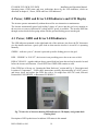
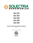
PVI 60KW, PVI 82KW, PVI 95KW
Installation and Operation Manual
PVI 60KW
PVI 82KW
PVI 95KW
INSTALLATION AND OPERATION MANUAL
Commercial, Grid-Tied Photovoltaic
Inverters
© 2010, Solectria Renewables LLC
Subject to Change
DOC-020099 rev 041
1
PVI 60KW, PVI 82KW, PVI 95KW
Installation and Operation Manual
IMPORTANT SAFETY INSTRUCTIONS
In this manual “Inverter” or “Inverters” refers to the inverter models: PVI 60KW, PVI 82KW and PVI 95KW unless
one of the specific models is noted.
This manual contains important instructions that shall be followed during installation and maintenance of the PVI
60KW, PVI 82KW AND PVI 95KW Inverter.
To reduce the risk of electrical shock, and to ensure the safe installation and operation of the inverter, the following
safety symbols are used to indicate dangerous conditions and important safety instructions.
WARNING: This indicates a fact or feature very important for the safety of the user and/or which
can cause serious hardware damage if not applied appropriately.
Use extreme caution when performing this task.
NOTE: This indicates a feature that is important either for optimal and efficient use or optimal
system operation.
EXAMPLE: This indicates an example.
SAVE THESE INSTRUCTIONS
DOC-020099 rev 041
2
PVI 60KW, PVI 82KW, PVI 95KW
Installation and Operation Manual
IMPORTANT SAFETY INSTRUCTIONS
•
All electrical installations shall be performed in accordance with the local and national electrical
codes ANSI/NFPA 70.
•
The Inverter contains no user serviceable parts. Please contact Solectria Renewables or a Solectria
Renewables authorized system installer for maintenance. (Appendix C for Solectria Renewables
contact information and authorized system installers.)
•
Before installing or using the Inverter, please read all instructions and caution markings in this
manual and on the Inverter unit as well as the PV modules.
•
Connection of the Inverter to the electric utility grid must be done after receiving prior approval
from the utility company and must only be performed by qualified personnel.
•
Completely cover the surface of all PV-arrays with opaque (dark) material before wiring them. PV
arrays produce electrical energy when exposed to light and could create a hazardous condition.
•
The inverter enclosure and disconnects must be locked (requiring a tool or key for access) for
protection against risk of injury to persons. The enclosure includes a lockable handle and comes
with a key. Keep the key in a safe location in case access to the cabinet is needed. (A replacement
for a lost key can be obtained from Solectria Renewables.)
SAVE THESE INSTRUCTIONS
PRESCRIPTIONS DE SECURITE IMPORTANTES
•
Tous les travaux d’installation électrique doivent être exécutés en conformité aux normes
électriques locales ainsi qu’à la norme nationale américaine et canadienne ANSI/NFPA 70.
•
Le PVI 60KW / PVI 82KW / 95KW ne contient aucune pièce requérant un entretient effectué
par l‘utilisateur. Pour toute maintenance, veuillez consulter Solectria Renewables ou un installateur
agréé par Solectria Renewables (les coordonnées de Solectria Renewables et des installateurs
agréés sont indiquées sur le site web de Solectria Renewables: www.solren.com).
•
Avant d’installer ou d’utiliser le PVI 60KW / PVI 82KW / PVI 95KW, veuillez lire toutes
instructions et toutes les mises en garde présentes dans ce manuel, sur le PVI 60KW / PVI 82KW /
PVI 95KW et sur les modules PV.
•
Le raccordement du PVI 60KW / PVI 82KW / PVI 95KW au réseau électrique ne doit être
effectuée qu’après avoir obtenu une entente d’interconnexion auprès de la compagnie locale de
distribution électrique et uniquement par du personnel autorisé et qualifié.
•
La surface de tous les capteurs PV doivent être recouverte entièrement d’un matériel opaque
(noir) avant de procéder au câblage. Les capteurs PV exposés a la lumière produisent du courant
électrique susceptible de créer une situation de risque.
CONSERVEZ CES INSTRUCTIONS
DOC-020099 rev 041
3
PVI 60KW, PVI 82KW, PVI 95KW
Installation and Operation Manual
Table of Contents
1
2
3
4
5
6
7
8
Introduction………………………………………………………………..………… 5
Installation…………………………………………………………………..……….. 6
2.1
Checking for Shipping Damage…………………………………...………. 6
2.2
Inverter Mounting.……………………………………………..…………. 6
2.3
Electrical Connection and Connection to Electrical Utility Grid and
Surge/Lightning Protection. …………………………………………….... 10
Commissioning the Inverter PV System …………………………………………… 17
Power, GFDI and Error LED Indicators and LCD Display……………………..….… 19
4.1
Power, GFDI and Error LED Indicators………………………………….. 19
4.2
LCD Display……………………………………………………………… 22
Troubleshooting & Opening the Main Enclosure………….………………...……… 24
Product Warranty and RMA Policy………………………………..………………. 29
Technical Data…………………………………………………..…………….……. 34
Pin Assignment for RS-232 and RS-485 communication connector……………… 39
Appendices…………………………………………………………………...……… 40
Appendix A Datasheet: PVI 60KW, PVI 82KW, PVI 95KW……………...………40
Appendix B String Sizing Examples……………………… ……………...……… 40
Appendix C Contact Information, Dealers and Installers ………………...……… 41
Appendix D UL1741 Listing Letter ……………………………………………… 42
DOC-020099 rev 041
4
PVI 60KW, PVI 82KW, PVI 95KW
Installation and Operation Manual
1 Introduction
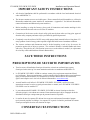
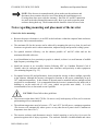
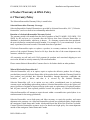
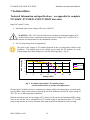
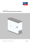
The PVI 60KW, PVI 82KW and PVI 95KW are commercial, 3-phase grid-tied PV inverters
designed to be inter-connected to the electric utility grid. With this manual the Inverters can be
installed and operated safely. This installation guide is used as reference for the commissioning
and as a guideline on how to use the inverter most effectively.
Feeding power into the grid involves conversion of the DC-voltage from the PV-array to grid
compatible AC-voltage by “inverting” DC to AC. This unit feeds power into a standard 480VAC,
3-phase commercial, industrial or institutional facility’s electrical system which is connected to the
electrical grid. (208VAC, 240VAC and 600VAC versions are also available, and custom 380VAC
versions – request different manual that covers 380VAC versions.)
If the PV system and inverter are providing the same amount of electrical power that the facility is
using then no power is taken from or fed into the utility grid. If the facility is using more power
than the PV system is providing, then the utility grid provides the balance of power. If the facility
is using less power than the PV system is generating, then the excess is fed into the utility grid.
Be sure to look into local regulations regarding Net Metering/inter-connection in your local area.
Note that some utilities need to change their revenue kWh meter for proper Net metering
measurement and billing.
PV Array
PVI 60KW, PVI 82KW or
PVI 95KW Inverter
Fig. 1 Grid tied inverter application
DOC-020099 rev 041
5
Electrical
Grid
PVI 60KW, PVI 82KW, PVI 95KW
Installation and Operation Manual
2 Installation
WARNING: Before installing the Inverter, read all instructions and caution markings
in this manual and on the Inverter as well as on the photovoltaic modules.
WARNING: Electrical installation shall be performed in accordance with all local
electrical codes and the National Electrical Code (NEC) (Candian Electrical Code if
Canada), ANSI/NFPA 70.
WARNING: Connecting the Inverter to the electric utility grid must only be done
after receiving prior approval from the utility company and installation completed
only by qualified personnel/licensed electrician(s).
2.1 Checking for Shipping Damage
The Inverter is thoroughly checked and tested rigorously before it is shipped. Even though it is
bolted onto a rugged, oversized pallet or in a crate for delivery, the inverter can be damaged during
shipping by poor handling, trucking or transfer station activity.
Please inspect the inverter thoroughly after it is delivered. If any damage is seen please
immediately notify the shipping company to make a claim. If there is any question about potential
shipping damage, contact Solectria Renewables. A photo of the damage may be helpful.
Do not accept the unit if it is visibly damaged or if you note visible damage when signing shipping
company receipt. Note damage on shipping papers with the truck driver! Report damage
immediately to the shipping company. Do not remove the unit from pallet/packaging. If it is
determined that the unit must be returned, an RMA# must be obtained from Solectria Renewables.
2.2 Inverter Mounting
Removing inverter from pallet and moving inverter:
- Use a forklift or fork attachment on other equipment if lifting from the bottom. The equipment
must be rated for at least 2000-2500lb since the inverter is about 1600-1750 lb. The forks should
be set at a 27-28" outside spacing so they fit just in between the inverter's 4 x 4" aluminum tube
feet. Before lifting, make sure forks are against the inside edges of both feet.
- Once off the pallet a pallet jack can also be used to roll the unit on a floor. Use a 27” wide jack.
- Alternatively, the inverter can be lifted using the lifting eyes on the top. If using this lifting
method, lift with vertical chains and hooks connected to a proper lifting device. Do not lift with an
"A" chain between the two eyes as this could bend the inverter's roof.
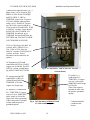
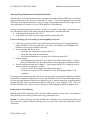
The Inverter is comprised of a rainproof industrial enclosure containing electrical and electronic
components including a transformer, filters, a contactor (for zero night-time power consumption),
fuses, a sealed IP62 power & control electronic inverter unit (DMG I660) and AC and DC
disconnects mounted on the sides of the main enclosure.
DOC-020099 rev 041
6
PVI 60KW, PVI 82KW, PVI 95KW
Installation and Operation Manual
NOTE: If the Inverter is mounted outside, please make sure the enclosure and
disconnect doors remains closed in case of rain during the installation process.
(Leaving these doors open voids the warranty.) Since the AC and DC connections
are made in the side-mounted disconnects only, there is no need to open the main
enclosure during hook-up. The disconnect doors should be closed in case of rain.
Notes regarding mounting and placement of the inverter
Criteria for device mounting:
•
Because the power electronics is in an IP62 sealed enclosure within the rainproof main enclosure,
the inverter can be mounted outdoors.
•
The maximum life for the inverter can be achieved by mounting the unit in a clean, dry and cool
location even given the unit’s robust construction, rainproof design and powerful cooling system.
•
For optimal electrical efficiency, use the shortest possible AC and DC cables and use the
maximum allowable cable size.
•
Avoid installation in close proximity to people or animals, as there is a small amount of audible
high-frequency switching noise.
•
Install the inverter in an accessible location following NEC (or Canadian Electrical Code if
Canada) codes for enclosure and disconnect door clearances and proximity to other equipment.
(See mounting diagram, Fig. 2.2)
•
For optimal inverter life and performance, do not mount the inverter in direct sunlight, especially
in hot climates, although the inverter is designed to function at full power continuously in up to
50oC ambient temperatures. In hot climates if the unit must be mounted in direct sunlight a metal
sun-shield is recommended. It is recommended that the inverter is mounted on the north side of
buildings or on the north side of a PV array (which can provide some shade). It is also
recommended to face to door north or east if possible.
CAUTION: Please follow these guidelines:
•
The inverter weighs about 1600-1750 lbs. Be sure to verify load capacity of floor, roof or concrete
pad mounting area (recommended).
•
The ambient temperature must be between –25oC and +50oC for full power, continuous operation.
(The inverter will automatically reduce power or may shut down to protect itself if ambient air
temperature rises above 50oC.).
•
The inverter enclosure and disconnects must be locked (requiring a tool or key for access) for
protection against risk of injury to persons. The enclosure includes a lockable handle and comes
DOC-020099 rev 041
7
PVI 60KW, PVI 82KW, PVI 95KW
Installation and Operation Manual
with a key. Keep the key in a safe location in case access to the cabinet is needed. (A replacement
for a lost key can be obtained from Solectria Renewables.)
•
The National Electrical Code (NEC) (or Canadian Electrical Code) requires that the inverter be
connected to a dedicated circuit and no other outlets or device may be connected to this circuit.
See NEC Section 690-64(b)(1). The NEC (or Canadian Electrical Code) also imposes limitations
on the size of the inverter and the manner in with it is connected to the utility grid. See NEC
Section 690-64(b)(2).
•
The cooling air exhausts at the bottom of the unit. Nothing should block the 4” clear space under
the enclosure defined by the 4” tall mounting feet.
•
A minimum distance of 12 inches (300mm) must be clear above the inverter for ventilation.
•
The inverter must be mounted with at least a 4” open space behind it. Air should be able to flow
up behind the unit from below it to above it.
•
If you are installing the inverter in a utility vault or electrical closet, the air circulation must be
sufficient for heat dissipation – provide external ventilation, to maintain an ambient condition of
less than 50oC. The ambient temperature should be kept as low as possible at all times.
•
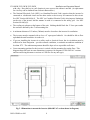
Correct mounting position for the inverter is vertical with the mounting feet on the floor. This
diagram shows the basic inverter dimensions (contact us for diagrams of 208-240VAC versions
and forward-facing disconnect versions or CAD files for any unit type):
Fig. 2.1 Dimensions to mount the inverter (480-600VAC version shown in diagram).
DOC-020099 rev 041
8
PVI 60KW, PVI 82KW, PVI 95KW
Installation and Operation Manual
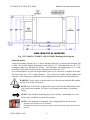
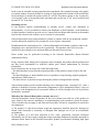
Fig. 2.2 PVI 60KW, PVI 82KW AND PVI 95KW Mounting Hole Diagram
Mounting Details
Using the mounting diagram Fig. 2.2, choose whether floor/roof or concrete pad mounting will
be used. The inverter includes mounting feet with 4 holes (1/2”, 12mm diameter) on a 20” x 32”
rectangular pattern for attaching the inverter. Note that these 4 mounting holes are 2” inside
each corner of the main inverter enclosure dimensions which are 24” x 36”.
It is recommended to use four hot dip galvanized grade 5 or 8 steel bolts or stainless steel bolts.
The correct bolt size is 3/8” (10mm) diameter. Use a heavy lock washer and flat washer with
each bolt. After mounting is completed, remove shipping aids from front cowl and inside unit.
WARNING: Severe injury or death could occur if the inverter mounting fails and the
unit tips over or falls on a person.
NOTE: The 1630-1824 lb. weight of the inverter will exert this added load to floor,
roof or pad where mounted. Be sure to verify proper load capacity of mounting
surface.
NOTE: If the roof/floor mounting only uses the inverter’s mounting feet, be sure
you use all 4 available foot mount bolt positions.
NOTE: Once mounting is completed, remove shipping aids from the inverter
-
-
Packing material under cowl on front door
Packing material between large power cables and contactor inside upper portion of the
inverter.
DOC-020099 rev 041
9
PVI 60KW, PVI 82KW, PVI 95KW
Installation and Operation Manual
2.3 Electrical Connection and Connection To Electrical
Utility Grid
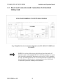
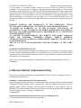
95KW 3-PHASE COMMERCIAL PV INVERTER BLOCK DIAGRAM
PVI 95KW
Fig. 3 Simplified electrical connection diagram for the PVI 60KW, PVI 82KW and
PVI 95KW
NOTE: For versions of the inverter which do not have fuses in the AC
disconnect (such as the standard 208VAC or 240VAC versions or a version
with a specially requested AC disconnect), refer to NEC 240.21 regarding
the “tap” rule and requirements for over-current protection of output wiring
based on distance to dedicated over-current protection fuse of dedicated
circuit breaker protection within specified distances.
DOC-020099 rev 041
10
PVI 60KW, PVI 82KW, PVI 95KW
Installation and Operation Manual
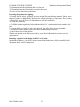
LED
indicators
Main enclosure
with integrated
inverter,
transformer
filters and
contactor
LCD Display
& Keypad
AC
Disconnect
DC
disconnect
with fused
PV combiner
(if equipped)
Nameplate, specs
and ETL, UL1741
(IEEE1547)
Certification labels
Warning
Label
Cooling Air
Intake
Exhaust Air
Output (also two
vents on back
wall)
Fig. 4 “Integrated Inverter Package” (480 - 600VAC unit shown)
WARNING: All electrical installations shall be done in accordance with all local
electrical codes and the National Electrical Code (NEC) (or Canadian Electrical Code),
ANSI/NFPA 70. Only make AC and DC connections directly to AC and DC
disconnects.
The negative DC, Photovoltaic connection is grounded within the inverter through the
ground fault detection and interrupt circuit (GFDI). The PV negative should not be
grounded at any other point in the system. The PV positive must never be grounded at
any time.
When conduit hubs are used on the AC and DC disconnect boxes in an outdoor or wet
location, rain-tight or wet location hubs that comply with the requirements in the
Standard For Fittings For Conduit and Outlet Boxes, UL514B, are to be used.
For AC, 3-phase wiring, first verify proper phase sequence, and then use 1 AWG,
(recommended for the 480VAC version) minimum 90oC (194oF), copper wire for
connection with the inverter’s 3-phase AC disconnect. Disconnect terminals listed for
DOC-020099 rev 041
11
PVI 60KW, PVI 82KW, PVI 95KW
Installation and Operation Manual
o
75 C. See NEC 310.10 regarding temperature ratings of wire. (2AWG recommended
for the 600VAC version and 250KCMIL wire is the recommended minimum wire size
for the 208VAC version.) Torque terminal screws to 275 in-lb on the 480VAC version
and 340 in-lbs on the 208VAC version. Voltage drop and other considerations may
dictate that larger wire sizes be used. A maximum of 250KCMIL copper conductor
wire on all 480 – 600VAC versions as well as 60kW unfused 208 and 240VAC
versions and 750KCMIL maximum for the fused 60kW, 208-240VAC and both fused
and unfused 82 and 95kW 208-240VAC versions. Up to a 1/0 AWG copper ground
conductor can be used for both the 480-600VAC and 208-240VAC versions (AC
equipment ground, torque to 100in-lb). An additional AC ground lug is provided of the
same size in the 480-600VAC versions and a larger size in the 208-240VAC versions
which fits from 6AWG to 250KCM (torque to 275in-lb). Verify that any wire size
choices meet NEC (or Canadian Electrical Code) requirements. Parallel wiring for
current-carrying conductors may conform to code for AC (and/or DC) side of your
wiring to the inverter.
For DC wiring, if the inverter is not equipped with an integrated fused PV subcombiner, a minimum conductor size of 4/0, 90oC (194oF) copper wire must be used for
the DC (PV) positive and negative conductors. (Disconnect terminals listed for 75oC.
See NEC 310.10 regarding temperature ratings of wire.) A maximum of 750KCMIL
copper wire can be used for positive & negative conductors (or two 300KCMIL wires
for each positive and negative). Two lugs are provided for DC equipment ground and
grounding electrode conductor, a 6AWG-1/0 and 6AWG-250KCMIL lug in the DC
(PV) disconnect. Minimum recommended DC equipment ground wire is 3AWG,
however consult local codes. A 250KCM maximum DC equipment ground can be
connected to the standard lug if NEC (Canadian Electrical Code) and local code allows
it for your installation and configuration. Torque the (+) terminal screws to 550 in-lbs,
torque the (-) terminal screws to 340 in-lbs and the 6AWG-1/0 ground lug to 100 in-lbs.
A larger ground lug for 6AWG to 250KCM (torque to 275in-lb) is also provided in the
same location and this is useful if the PV conductors are upsized and it is necessary to
upsize the DC equipment ground conductor or the grounding electrode conductor (see
Grounding Electrode Conductor Section below).
Lightning and Surge Protection:
The inverter is designed with certain protections against surges in voltage including
certification to ANSI/IEEE 62.41/62.42 (as required in the NY SIR), however added
protection and solid grounding provisions are important for best protection against
utility surges and surges created by indirect lightning strikes.
The installation of a Delta lightning surge arrester or other UL listed arrester of the
correct specification is recommended on both the DC and AC sides of inverter. This
can be installed on the outside of the DC disconnect and wired using the manufacturer's
directions. This device gives important added protection from indirect lightning strikes
and resulting surges that provide protection beyond the inverter's UL1741
requirements. It is suggested to drive a ground rod specifically for the PV array. It is
also a very good idea to have the lightning protection system of the building checked
and upgraded if needed before the PV system is installed. (Are there air
conductors/lightning rods along the roof-line of the building well above the PV array?
Do you see a copper ground wire running from the air conductors to a ground rod?)
These added protections are especially important for area prone to thunder storms and
DOC-020099 rev 041
12
PVI 60KW, PVI 82KW, PVI 95KW
Installation and Operation Manual
possible nearby lightning strikes. Although these added precautions will not guarantee
that there will be no damage from lightning, they can help prevent or limit potential
damage.
Grounding Electrode Conductor (GEC):
As with all PV systems, a Grounding Electrode Conductor must be installed per
UL690.47 (and 250.166). This conductor should be sized according to these NEC
(Canadian Electrical Code) requirements. This conductor should be terminated on the
ground bar in the DC disconnect. If required, an additional lug of the appropriate size
for the grounding electrode conductor can be added in the DC disconnect and bonded to
the existing ground bar bolt in the disconnect or mounted elsewhere on the ground plate
to which the existing ground bar is attached. If the grounding electrode conductor is
required to be larger than 250KCMIL (the maximum size wire for the ground lug
provided), then the grounding electrode conductor should enter the lower section of the
main Inverter enclosure through a rain-tight conduit fitting and the conductor should be
terminated under the left side of the large aluminum shelf above the transformer on the
provided star/bonding point stud. This stud comes out of a (¼-20) PEM nut at the left
end of the aluminum angle support under the shelf. You should use an appropriate lug
for the conductor and corrosion-prevention grease between lug and aluminum bracket.
(If a longer stud is needed, replace with a longer ¼-20 bolt above which must be
threaded all the way up to the bolt head.)
WARNING: The wiring connections of the inverter to the DC-voltage from the PV
strings and the AC-voltage of the utility must be performed with the AC and DC
disconnects off, building AC source circuit panel/breaker off and the PV module strings
disconnected (or covered up).
•
Connect the building 3-phase conductors and AC equipment ground at AC
disconnect “LINE” terminals (L1, L2, L3) and ground bar. Phase sequence
MUST be correct (clockwise!). Must be checked with a phase rotation meter.
•
Connect the PV strings to the DC disconnect enclosure positive (switched)
terminal (+) and negative terminal. Connect the DC equipment ground to the
ground bar. (If positive grounded PV array, wire accordingly)
•
Connect PV modules, strings, combiners or uncover them.
•
Verify proper AC and DC voltages and DC polarity. Verify proper AC
phasing! The connection of the grid to the inverter must follow the L1/A, L2/B
and L3/C clockwise order. Test with a phase direction tester or a scope-meter.
Extech, Fieldpiece, Fluke and UEi make phase rotation meters. Do not assume
existing color code or building wiring is correct! NOTE: It may be necessary
to swap the phase A&B wires connecting the building circuit to the inverter’s
disconnect if building phasing or wiring anywhere between utility and the
inverter is not in proper phase sequence. Incorrect phase sequence at the 3phase AC connection in the AC disconnect can damage the inverter. Turn on
the inverter by switching building/utility 3-phase breakers ON then turning on
inverter’s AC disconnect followed by DC disconnect.
To disconnect the inverter from the building/utility grid, turn off the DC disconnect, then the AC
disconnect. Turn off the AC 3-phase building/utility breaker if needed.
DOC-020099 rev 041
13
PVI 60KW, PVI 82KW, PVI 95KW
Installation and Operation Manual
Connection to dedicated 480V AC, 3phase circuit, 125A circuit for PVI
60KW or 150A for the PVI 82KW
and PVI 95KW, 2 AWG to
250KCMIL copper wire. Torque to
275 in-lb. (Shown without plastic
safety cover). If 600VAC version,
use 100-110A circuit for 60kW or
125A circuit for 82 and 95kW. If 208
or 240VAC versions, circuit should
be 200-250A for PVI 60KW (1/0250KCMIL for unfused, up to
750KCMIL for fused) and 300A for
PVI 82KW and 350A for PVI 95KW
(250-750KCMIL all 82-95kW
125A or 150A Fuses (for 480V AC
version), 600V, FRS-R-125 or –
150. 110A or 125A fuses for
600VAC versions. (If 208-240VAC
versions, no fuses. Fused
disconnect can be ordered as an
option.)
AC Equipment (2) Ground
connections 6AWG to 1/0AWG
copper wire (100in-lb), For 208240VAC version, second larger
lug 6AWG-250KCM (275in-lb)
Fig. 5 AC disconnect (480 or 600 VAC inverter
version shown)
PV positive (+)
connections 4/0 –
750KCMIL (1) copper
wire (or 2 wires up to
300KCMIL each) torque
to 550 in-lb.
(This is the negative
terminal in units with
the positive grounded
option.)
PV equip ground & GEC
connections, 6AWG-1/0
(100in-lb) and 6AWG250KCMIL (275in-lb)
copper wire (larger lug)
PV negative (-) connections
4/0 - 750KCMIL (1) copper
wire (or 2 up to 300KCMIL
each); torque to 340 in-lbs.
Tape wires white (grounded).
(This is the positive terminal
in units with the positive
grounded option.)
DOC-020099 rev 041
Fig. 6 DC disconnect without a Fused
PV Sub-combiner option.
14
Customer/installer
conductors not
shown.
PVI 60KW, PVI 82KW, PVI 95KW
Installation and Operation Manual
WARNING: Fuses in the inverter’s AC disconnect must only be replaced with the
same type fuses installed.
Inverter Model
60kW
82kW and 95kW
60kW
82kW and 95kW
60kW
82kW
95kW
AC Voltage
480VAC
480VAC
600VAC
600VAC
208 or 240VAC
208 or 240VAC
208 or 240VAC
Fuse Type
600VAC RK5, FRS-R-125 125A
600VAC RK5, FRS-R-150 150A
600VAC RK5, FRS-R-110 110A
600VAC RK5, FRS-R-125 125A
250A RK5 FRS fuses or breaker
300A RK5 FRS fuses or breaker
350A RK5 FRS fuses or breaker
WARNING: If inverter is equipped with the fused PV sub-combiner, fuses in DC
disconnect must only be replaced with 600VDC rated fuses of the same type. Always
refer to PV module and combiner fuse ratings and specification before selecting or
replacing fuses.
Connection Wiring To Electrical Utility Grid
The PVI 60KW, PVI 82KW or PVI 95KW must be connected to the grid with 3 conductors and an
AC equipment-grounding conductor.
Inverter Model
60kW
82kW and 95kW
60kW
82kW and 95kW
60kW
82kW
95kW
AC Voltage
480VAC
480VAC
600VAC
600VAC
208VAC
208VAC
208VAC
Breaker required
125A
150A
110A
125A
250A
300A
350A
The grid impedance value at the connection point should be as low as possible to avoid an increase
of the AC-voltage to non-permissible values while the inverter feeds to the grid. Minimizing
wiring impedance also results in higher system efficiency.
EXAMPLE: The impedance is the sum of the electricity grid impedance at building
distribution and all impedance values of conductors and connections.
Single conductor impedance values are:
DOC-020099 rev 041
15
PVI 60KW, PVI 82KW, PVI 95KW
Installation and Operation Manual
• Approximately 0.04 Ohm for 250 feet (76.2 m) 2 AWG conductors
•
Approximately 0.025 Ohm for 250 feet (76.2 m) 1/0 AWG conductors
•
Approximately 0.012 Ohm for 250 feet (76.2 m) 4/0 AWG conductors
•
Conductor impedance of < 0.025 Ohm is recommended
It is recommended that the total impedance phase to phase of the grid plus the interconnecting AC
conductors should be less than 0.035 Ohm for the 480-600VAC versions and about ½ this, or
0.015 Ohm for the 208-240VAC versions.
Connection of the PV-panels to the DC disconnect enclosure with or without
integrated fused PV sub-combiner
WARNING: Follow PV module and combiner manufacturer directions. PV-arrays
produce electrical energy when exposed to light and could create a hazardous
condition. (One method used to assure safety from shock is to completely cover the
surface of all PV-arrays with opaque (dark) material before wiring them.)
Depending on the type of PV-modules used it is possible to use different numbers of parallel
strings. (Appendix B shows some example PV string sizing tables.)
WARNING: Before connecting the connectors of the PV-panel to the DC disconnect
enclosure fused PV sub-combiner (if equipped) or + and – terminal block if not
equipped with combiner check the correct polarity and admissible PV-panel voltage
between the + and the - cable connectors of the PV panel.
The PV-panel open circuit voltage must be below 600V DC (Vpv < 600V DC) under
all conditions as per NEC 690-7. Please read the Technical Info section and see PV
string sizing table in Appendix B.
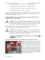
Inverter with optional fused PV sub-combiner in DC disconnect enclosure:
There are up to 8 fuse blocks for up to 8 PV subcombiner connections (from 40-250A fuses). The
positive (+) wire from each string is connected to
each fuse block bottom screw terminal. There are
also up to 8 negative positions to be used for
negative (-) connections on the negative (-) terminal
block. Conductors from array field combiners to
inverter sub-combiner fuse holder terminals must be
sized according to the paralleled string group
(combined) current ratings with appropriate
multipliers/de-rating per NEC (Canadian Electrical
Code) and must be taped white.
DOC-020099 rev 041
16
PVI 60KW, PVI 82KW, PVI 95KW
Installation and Operation Manual
Inverter without fused PV sub-combiner in the DC disconnect enclosure:
There are positive and negative terminals for connection of a combined PV power feed from a
customer-provided external fused PV combiner system.
WARNING: A fused, correctly rated PV combiner and in some cases, sub-combiner,
must be used with this version of the inverter.
WARNING: Even when in the off position, the DC disconnect will remain live on
the PV side (“line”) when the PV modules are in daylight. The inverter (“load”) side
of the disconnect will also remain live after the disconnect has been shut off until 60
seconds after the LEDs turn off, as electrolytic DC bus capacitors in the inverter
discharge.
Inverters connected in conjunction with emergency back-up generators:
Please follow all applicable NEC (Canadian Electrical Code) and local codes.
The inverters meet and are certified to all UL1741 and IEEE1547 requirements.
There are two methods to connect inverter or inverters to a grid-connected building that includes
an emergency generator: (note that these are only thoughts on this subject – consult your inspector)
1.) Inverter(s) on the grid-side of the transfer switch that disconnect the building when the utility
goes off. With this method, when the grid goes off, the inverters go off, the transfer switch
disconnects the building from the PV inverters and grid. Then the generator starts and runs for the
duration of power outage. In this case, the inverter is on the grid-side of the transfer switch and
the inverters remain off the entire time until the grid returns.
2.) Inverter(s) on the load/building side of the transfer switch that disconnect the building when the
utility goes off. With this method when the grid goes off, the inverters go off, the transfer switch
disconnects the building with inverter(s) from the grid and the generator starts, the inverter(s) will
attempt to start in parallel with the building/load/generator. With a large size generator and load,
the inverter will most likely come back on and run well. If at any time the voltage or frequency of
the system goes outside of the limits set in UL1741, then the inverter will go off and re-start 5
minutes later. This trial and restart sequence should not cause any trouble for the building,
generator or inverter, however, if the PV system has close to or more than the power level of the
generator and/or loads at any time, it is not recommended to use this hook up configuration (with
the inverter on the building/load side of the transfer switch)
3 Commissioning the Inverter PV System
The inverter is mounted, all connections are made and you are ready to power it up.
NOTE: Make sure all tools; parts, etc. are removed from the vicinity of the inverter
before turning on.
WARNING: Make a final check for correctness of all AC and DC wiring to the
inverter and in the system.
DOC-020099 rev 041
17
PVI 60KW, PVI 82KW, PVI 95KW
Installation and Operation Manual
NOTE: With the PV modules connected and inverter disconnects still off, it is a
good final precaution to check PV voltage and polarity once more simply by
carefully using a 600V, DC rated digital volt meter and probing the positive (+) and
negative (-) PV connections in the disconnect enclosure. Verify clockwise AC
phase rotation for L1, L2, L3 using a phase rotation meter.
Turning on the inverter:
•
Turn on the dedicated 3-phase (dedicated) circuit breaker on the building electrical panel.
•
Verify the proper CLOCKWISE phase sequence at the “line” side terminals (top) of the
AC disconnect. Do NOT turn on until clockwise phase sequence has been verified!
•
Turn on the Inverter’s 3-phase AC disconnect.
•
If equipped with Fat Spaniel Inverter-Direct monitoring option, refer to Fat Spaniel
PV2Web Installation Manual for gateway startup sequence before turning on inverter’s DC
disconnect.
•
Turn on the Inverter’s DC disconnect.
•
Watch the LED indicators for initialization (all three LEDs on), then slow blinking green
LED followed by faster blinking green LED.
•
Listen for contactor clunk (inverter on-line).
•
Listen for slight 60 Hz hum (transformer on-line).
•
Following the blinking green LED and high frequency switching sound you should see a
solid green LED (inverter on-line and beginning to feed power into 3-phase circuit). This
confirms that the inverter is operating normally.
Operation:
The control electronics and DSP will be active as soon as DC (PV) voltage reaches 300V DC. The
inverter will go on-line with the utility/building 3-phase grid when the DC voltage first exceeds
400V DC (strike voltage). Next, the inverter will load the array, bringing the DC voltage down
from 400V DC to not less than 325V DC.
Once there is enough PV power at 325V DC to back feed 3-phase AC power switching will
automatically feed power to the grid.
Because the inverter goes completely off line at night or in dark conditions when no power can be
produced, there are no idling losses, adding 1-2% additional energy production annually over an
inverter design that remains on all the time.
DOC-020099 rev 041
18
PVI 60KW, PVI 82KW, PVI 95KW
Installation and Operation Manual
Operating states, GFDI status and error indications shown by the LED indicators, which are
described in chapter 4, “Power, GFDI and Error LED Indicators”.
4 Power, GFDI and Error LED Indicators and LCD Display
The inverter operates automatically without the need for user interaction or maintenance.
The Inverter automatically starts back feeding 3-phase AC power into the grid every morning as
the sun rises, as soon as sufficient DC voltage and PV power is available. The inverter DSP runs
through various checks before going online with the grid and feeding power into the grid.
4.1 Power, GFDI and Error LED Indicators
The LED indicators mounted on the right-hand side of the enclosure just above the DC disconnect
give the installer and user a good, quick look at what state the inverter is in and if it is operating
normally.
GREEN – indicates “power”, the unit is powered up and/or feeding power to the grid
RED – “ERROR” or “FAULT”, the inverter is not providing power due to an error or fault
RED & YELLOW – together indicate that a ground fault has been detected and it must be located
before the inverter will function. Check GFDI fuse if RED LED remains as solid.
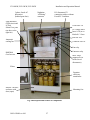
If the GFDI fuse is blown, see “Opening the Main Enclosure” section and Fig. 8, “Description and
Location of Components”. Follow these instructions carefully (disconnecting AC & DC power)
and locate, check and replace the GFDI fuse with a 2A midget fuse 600V DC rated, Solectria
Renewables P/N KLKD002, or Bussmann P/N KLKD-2.
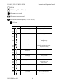
Fig. 7 Front view of inverter showing LED indicators, LCD display and ground fault
warning label
Description of LED symbols used to indicate LED status in this manual
DOC-020099 rev 041
19
PVI 60KW, PVI 82KW, PVI 95KW
Installation and Operation Manual
LED Off
LED flashing (25% on, 75% off)
LED on once per second
LED on two times per second
LED on with short interruptions (75% on, 25% off)
LED on
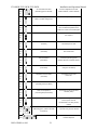
LED indicator
green:
Operating condition
Description
standby (night)
input voltage < 125 VDC
initialization
unit is being initialized
stop
Input voltage low < 325V
yellow:
red:
green:
yellow:
red:
green:
yellow:
(400V @ startup)
red:
green:
stop
input voltage high > 570V
yellow:
(600 VDC is the maximum allowable
red:
PV open circuit voltage)
green:
yellow:
waiting for
stronger sun
available DC power is too low
waiting,
checking grid
presence of valid grid conditions
red:
green:
yellow:
Is being checked
red:
green:
starting / synchronizing
-starting transformer
yellow:
-synchronization to grid
red:
-closing contactor
green:
yellow:
waiting for
AC disconnect/breaker to be closed
grid voltage
Is absent
AC fuse blown
(one phase)
One AC power fuse blown
red:
green:
yellow:
Or one v-sense fuse blown
red:
DOC-020099 rev 041
Or one grid phase off/blown
20
PVI 60KW, PVI 82KW, PVI 95KW
green:
yellow:
Installation and Operation Manual
AC VOLTAGE TOO HIGH
(alternating green & red LED)
AC Grid Voltage above UL limits
(>228V if 208VAC, >528V if 480VAC)
feeding grid
MPP or constant voltage mode
normal daytime operation
red:
green:
yellow:
red:
green:
de-rating mode or inverter at full power
reduction of power fed to the grid
yellow:
due to increased temperature of the
red:
heatsink or inverter is at full rated power
green:
GFDI fuse failure
GFDI fuse is defective
see chapter 5
green:
Contactor Failure
yellow:
(one blink)
Contactor timer run out before
successful open or close
yellow:
red:
red:
green:
Vsense Failure
yellow:
(two blinks)
DSP board cannot communicate
with vsense board
red:
green:
Thermal Overshot
yellow:
(three blinks)
Contactor open during power
operation because of thermal overshot
red:
green:
Current Sensor Failure
yellow:
(Four blinks)
Current sensor failed self-calibration
during the unit wakeup
red:
green:
Temperature Sensor Failure
yellow:
(five blinks)
Temperature sensor read
below -30C
green:
Desat Failure
Power stage desaturation failure
yellow:
(one blink (pause) two blinks)
red:
red:
green:
IGBT over temperature
yellow:
(one blink (pause) three blinks)
Power stage junction temperature
over limit (125C)
Utility Failure
A failure of the Utility (i.e. a blackout or
red:
green:
yellow:
brownout) has occurred
red:
Unit will restart 5 min after grid (AC)
restored
green:
5 minute wait for re-start
Utility required 5 minute wait for restart
yellow:
(alternating green, yellow & red LEDs
in process since grid (AC) restored
red:
in sequence)
green:
Wong AC Phase Sequence
yellow:
DOC-020099 rev 041
Switch two phase wires for correct
clockwise sequence
21
PVI 60KW, PVI 82KW, PVI 95KW
Installation and Operation Manual
red:
4.2 LCD Display
Button Description
ESC: To move up a level from the current menu.
↑↓: To scroll up/down the individual menu items
↵: To enter into selected menu.
Main/Default Screen
Eac: XXXX kWh
Pac:
XX W
Press any of the following keys to move from the main/default screen into the Start Menu↑↓↵
To enter into selected menu item, press the ↵ key.
Start Menu
1. Measurements
2. Set Inverter
3. Set Monitor
4. KYZ Meter
5. Display Info
DOC-020099 rev 041
22
PVI 60KW, PVI 82KW, PVI 95KW
Installation and Operation Manual
Measurements Menu
This displays the data retrieved from the inverter. Use the ↑↓ buttons to move up and down the list:
AC Energy
AC Power
AC Voltage
AC Current (3 phase average)
DC Voltage
Pressing ESC will take the screen back to the start menu.
Note: data will only be available when inverter is awake and communicating.
Set Inverter Menu
Displays inverter parameters, some of which may be modified with the keypad.
1. Inverter ID
Serial port address/ID of the inverter
Serial port baud rate
(Currently not adjustable)
2. Baud Rate
3. Vac Very High
AC Voltage Critical High
4. Vac High
AC Voltage High
5. Vac Low
AC Voltage Low
6. Vac Very Low
AC Voltage Critical Low
AC Frequency Low
7. Fac Low
8. Fac Very Low
AC Frequency Critical Low
9. Fac High
AC Frequency High (Not adjustable)
Note: data is only available when inverter is awake and communicating.
Monitor Menu
Displays monitor settings that may be modified with the keypad.
1. LAN
1. DHCP Mode
2. Static/Fallback IP
3. Gateway IP
4. Netmask
Local Area Network configuration, applicable only for
SolrenView monitoring
See SolrenView manual on DHCP
If DHCP is turned on, this is then used as the fallback
IP
IP address of LAN’s default gateway.
Subnet mask
2. Date/Time
Manual time set. This may be overwritten by
scheduled NIST updates.
3. Reboot
Reboots the monitor
4.
Remote SRV
DOC-020099 rev 041
This starts the transmit process necessary for
SolrenView monitoring. Units that are ordered with
23
PVI 60KW, PVI 82KW, PVI 95KW
Installation and Operation Manual
SolrenView monitoring will have this field turned on.
Caution: Enabling this field when SolrenView service
has not been confirmed/authorized may result in
unnecessary wear on the unit.
5.
Reset SRV
Settings are cleared to factory defaults. Caution: This will also
clear Revenue-grade KYZ counters.
KYZ Meter Menu
Displays KYZ readings, if installed. See Solrenview manual for KYZ installation.
1.
2.
3.
AC Energy
AC Power
Pulse Weight
Cumulative energy count
Power reading
Multiplier to convert pulses to WH for display. F
For example Pulse Weight = 10 WH
1 pulse = 10 WH
5 Troubleshooting and Maintenance
The Inverters are designed, produced and rigorously tested for long life and reliability in a wide
range of climate conditions, voltage and power levels.
With a properly shipped, sited, mounted, wired and tested installation, the integrated inverter units
should give many years of trouble-free service.
The following trouble shooting information will help in the event that the inverter does not
function, stops functioning or does not provide full performance.
WARNING: Before attempting to open disconnects or the main enclosure, read the
entire manual, especially warning messages and “Opening The Main Enclosure” later
in this section. Only qualified personnel should attempt to open any of these
enclosure doors or do any service or troubleshooting.
PV system not functioning
•
•
•
•
•
•
Check LED indicator status and LCD display
Check connection to grid, 3-phase AC power, clockwise phase rotation (with meter)
Check DC (PV) string connections or main PV feed conductor connections
Verify PV voltage range including hot module temperature MPP voltage and cold module
temperature, open circuit voltage (OCV)
Contact installer or Solectria Renewables if malfunction persists
If contacting Solectria Renewables for assistance, please provide part number, serial
number, short description of problem (LED indicator status, when problem started, how
often problem occurs, under what conditions the problem occurs) and information on PV
modules (string layout, number of modules per string, number of strings, module model
and part number, output power, short-circuit current and open circuit voltage)
DOC-020099 rev 041
24
PVI 60KW, PVI 82KW, PVI 95KW
Installation and Operation Manual
Some specific problems that can be identified quickly
GFDI Problem: If the LED indicators show a ground fault problem but the GFDI fuse is not blown
then a ground fault in PV array or wiring must be found. If the LED indicators show that the
GFDI fuse is blown, the fault in PV array or wiring must be found and GFDI fuse replaced. For
fuse replacement, see section 4 “Power, GFDI and Error LED Indicators”.
Inverter over-heating and power de-rating: If the power output is lower than normal and there is
an LED indication of power de-rating due to high temperature, check the following
• Is the ambient air temp above 45-50oC?
• Is the intake (front) louver grill or output (bottom) visibly blocked?
Unit over heating, power de-rating, or unit not putting out power
•
•
•
•
Check insect screens in front louver grill on main enclosure door for clogging from dust,
pollen and debris. The louver/grill can be removed with 18 Philips screws holding it on
and insect screen can be cleaned or replaced.
Fan not running, blocked or slow
o Check fan fuse inside main enclosure (10A) AC.
o Check fan relay inside main enclosure.
o Check the fan and make sure it spins freely (when unit turned off).
No grid sensing
o Grid sensing fuses blown (0.5A or as labeled) AC inside main enclosure. Contact
Solectria Renewables (Do not replace fuses, as this represents an abnormal failure).
No LED indications when sun is shining. If grid voltage and DC (PV) voltage is present
and no response from inverter is evident
o Verify AC & DC (PV) voltages are within proper ranges.
o Verify fuses in AC & DC (PV) disconnect are good (if equipped with PV subcombiner).
If at some point it is determined that the unit or any part of the unit should be shipped to Solectria
Renewables for repair or replacement, be sure to get an RMA# from Solectria Renewables and use
the same packing method as when it was shipped to you, or request instruction on packing and/or
packing materials from Solectria Renewables to help insure a safe shipment. The 55 lb core
inverter electronics unit is easy to remove and replace (65lb shipping weight incl. shipping box).
Intake Louver Vent Cleaning
With the unit off, DC disconnect off (to prevent needless ingestion of more dust), for example do
early morning or late evening so little or no energy generation is lost.
Method 1: remove shroud by removing all Phil Pan #2 machine screws around shroud (sides and
top), and remove shroud. Without removing vent, use a powerful vacuum and clean entire louver
vent/screen.
DOC-020099 rev 041
25
PVI 60KW, PVI 82KW, PVI 95KW
Installation and Operation Manual
Method 2: remove vent by removing all Phil Pan #2 machine screws around shroud (sides and
top), and remove shroud. Next remove remaining bottom screws holding louver vent onto
inverter. Use compressed air from the back (insect screen) side of the louver vent/screen unit to
remove all debris. Re-assemble putting all screws in LOOSELY first and then tighten snug (do
not over-tighten).
Opening the Main Enclosure
Normally the main enclosure (or disconnects) will not have to be opened for any reason by the
user. If opening the unit is necessary follow these guidelines:
WARNING: The inverter should only be opened up by authorized and qualified
service personnel.
WARNING: Only open the inverter when it is clear and dry outside if the inverter is
outdoors. As with any electrical system do not work on it if there is a potential of an
electrical storm.
WARNING: Both DC and AC disconnects must be in the off position and wait 60
seconds after the LED indicators are off before opening as electrolytic capacitors on
the internal DC “bus” are discharging during this time.
•
•
•
•
Switch off DC disconnect
Switch off AC disconnect (and AC building panel circuit breaker)
Watch until all LED indicators have been off for 60 seconds (if not already off)
Open handle on door (use key if locked)
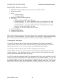
See Fig. 8 and “Inside the Main Enclosure You Will See” section that follows.
DOC-020099 rev 041
26
PVI 60KW, PVI 82KW, PVI 95KW
3 phase, fused AC
disconnect
(behind open door)
Installation and Operation Manual
Nighttime
“off-lining”
contactor
DC disconnect PV
connection with or without
Fused PV Combiner
LED indicators,
GFDI circuit and
LCD &
SolrenView ports
(on door, to the
right fan)
GFDI Fuse 2A
AC voltage sense
fuses 0.5A (or as
labeled)), 3 fuses
Fan fuse 10A
Automatic
cooling fan
Contactor fuse 3A
Fan relay
Contactor relay
DMGI660
Core Inverter
MOV surge
suppressors (or
located in on
disconnects)
Filters
Premium
efficiency
transformer
NEMA 3 inverter
enclosure with
door (open)
Mounting feet
Fig. 8 Description and location of components
DOC-020099 rev 041
27
PVI 60KW, PVI 82KW, PVI 95KW
Installation and Operation Manual
Inside the Main Enclosure you will see:
•
•
•
•
•
•
•
•
DMGI660 Controller and power electronics inverter module with fan
Isolation transformer
Filters
o 3 Round Torroids
o 1 Rectangular Filter
Night-time 3-phase off-lining contactor
Fuse blocks
o GFDI 2A DC fuse KLKD, 600 VDC rated
o Grid Sense Phase A, 0.5 A (or as labeled) AC Fuse (L1), KLM, 500 VAC rated
o Grid Sense Phase B, 0.5 A (or as labeled) AC Fuse (L2), KLM, 500 VAC rated
o Grid Sense Phase C, 0.5 A (or as labeled) AC Fuse (L3), KLM, 500 VAC rated
o Fan 10 A, AC Fuse, KLM, 500 VAC rated
o Contactor 3 A, AC Fuse, KLM, 500 VAC rated
Fan Control Relay
Contactor Control Relay
GFDI/LED Indicator PCB
Before closing the main enclosure always check for any signs of problems such as corrosion, loose
parts, insect or animal infestation, excessive dirt/dust or over heated or deformed/aged-looking
parts. Also be sure if any wires were moved or cable ties cut, that they are replaced as new.
To Open the DC Disconnect:
To open DC disconnect while off: (note that certain terminals are live inside even when off)
Turn the Bottom release screw counter clockwise and the gray aluminum handle will flip to the
right (counter-clockwise). You can now open the door using the aluminum handle.
To open DC disconnect while on: (note that ALL terminals are live when on)
Turn the Bottom release screw counter clockwise and the aluminum handle will flip to the right
(counter-clockwise). Next, turn the upper screw counter-clockwise while pulling the door open
with the aluminum handle and the door should open.
Do NOT force the gray aluminum handle. The disconnect safety latch is only operable with a flat
screwdriver in the lower shrouded screw which should release the aluminum handle. You can spin
the aluminum handle around in the counter-clockwise direction and it goes "click, click, click" as it
turns, however this does wear out the mechanism. Nothing is broken in this case. Just turn the
handle until it is at the 4:00 position when the door is open (or 6:00 position when door is closed.)
DOC-020099 rev 041
28
PVI 60KW, PVI 82KW, PVI 95KW
Installation and Operation Manual
6 Product Warranty & RMA Policy
6.1 Warranty Policy
The Solectria Renewables Warranty Policy is stated below.
Solectria Renewables Warranty Coverage:
Solectria Renewables Limited Warranties are provided by Solectria Renewables, LLC. ("Solectria
Renewables") and cover defects in workmanship and materials.
Duration of a Solectria Renewables Warranty Period:
The warranty period is 60 months from the date of purchase of the PVI 60KW / PVI 82KW / PVI
95KW by the end user or 64 months after the delivery date from Solectria Renewables to
distributor or dealer/installer, whichever is shorter. If a warranty extension has been purchased,
the term is defined as extension beyond 60 months. For example, if a 5-year extension (to 10 years
total) is purchased, the term becomes 120 months from date of purchase.
If Solectria Renewables repairs or replaces a product, its warranty continues for the remaining
portion of the original Warranty Period or 90 days from the date of the return shipment to the
customer, whichever is greater.
All warranties are null and void if full payment for products and associated shipping are not
received in full and in a timely manner by Solectria Renewables.
Please contact Solectria Renewables Customer Service for further details on other products.
What will Solectria Renewables do?
Solectria Renewables will, at its option, repair or replace the defective product free of charge,
provided that you notify Solectria Renewables of the product defect within the Warranty Period for
your product, and provided that Solectria Renewables, through inspection, establishes the
existence of such a defect and that it is covered by the Limited Warranty.
Solectria Renewables will, at its option, use new and/or reconditioned parts in performing
warranty repair and building replacement products. Solectria Renewables reserves the right to use
parts or products of original or improved design in the repair or replacement. All replaced products
and all parts removed from repaired products become the property of Solectria Renewables.
Solectria Renewables will attempt to repair the unit within a reasonable time period (there is no
reimbursement for lost energy production.)
Solectria Renewables covers both parts and labor necessary to repair the product, and return
shipment to the customer via a Solectria Renewables-selected non-expedited surface freight within
the contiguous United States and Canada. Alaska and Hawaii the Rest of the World are excluded.
Contact Solectria Renewables customer service for details on freight policy for return shipments
outside of the contiguous United States and Canada.
DOC-020099 rev 041
29
PVI 60KW, PVI 82KW, PVI 95KW
Installation and Operation Manual
In the event an extended warranty option has been purchased, this extended warranty only applies
to exposed outdoor locations (defined as rooftop or open/unprotected locations) if the product has
been purchased to include the gasket-sealed AC and DC disconnect option or has a protective
cover around 3 sides of inverter unit (back and sides) and over the top, 4”-60” away from back and
top and 30”-96” from sides.
Obtaining Service:
If your product requires troubleshooting or warranty service, contact your distributor or
dealer/installer. If you are unable to contact your distributor or dealer/installer, or the distributor
or dealer/installer is unable to provide service, contact Solectria Renewables directly at the number
listed on the website in the customer service section for your product.
Solectria Renewables may send personnel to a jobsite or contract with an area technician, installer
or other authorized, trained service personnel to service/replace components.
Reimbursement for contracted services: Solectria Renewables will submit a purchase order to the
designated service personnel before work is performed. This purchase order will cover time
expected for the required service and most likely an allocation for travel time.
Direct returns may be performed according to the Solectria Renewables Return Material
Authorization Policy.
In any warranty claim, dated proof of purchase must accompany the product and the product must
not have been disassembled or modified without prior written authorization by Solectria
Renewables.
Proof of purchase may be in any one of the following forms:
- The dated purchase receipt from the original purchase of the product at point of sale to the end
user, or
- The dated distributor or dealer/installer invoice or purchase receipt showing original equipment
manufacturer (OEM) status, or
- The dated invoice or purchase receipt showing the product exchanged under warranty.
Solectria Renewables provides trouble-shooting service Monday-Friday, 9am-6pm EST. Once a
problem is identified, necessary replacement component(s) will be dispatched within 1-2 days to
the jobsite or the designated service personnel's address or will be brought to the site by Solectria
Renewables’ personnel.
What does the Solectria Renewables warranty not cover?
Solectria Renewables Limited Warranties do not cover normal wear and tear of the product or
costs related to the removal, installation, or troubleshooting of the customer's electrical systems.
These warranties do not apply to and Solectria Renewables will not be responsible for any defect
in or damage to:
a) The product, if it has been misused, neglected, improperly installed, physically damaged or
altered, either internally or externally, or damaged from improper use or use in an unsuitable
environment;
b) The product, if it has been subjected to fire, water, generalized corrosion, biological
infestations, acts of God or input voltage that creates operating conditions beyond the maximum or
minimum limits listed in the Solectria Renewables product specifications including high input
DOC-020099 rev 041
30
PVI 60KW, PVI 82KW, PVI 95KW
Installation and Operation Manual
voltage
from
generators
and
lightning
strikes;
c) The product, if repairs have been done to it other than by Solectria Renewables or authorized,
trained service personnel;
d) The product, if it is used as a component part of a product expressly warranted by another
manufacturer;
e) The product, if its original identification (trademark, serial number) markings have been
defaced, altered, or removed;
f) The product, if it has been damaged in shipping (unless approved in writing by Solectria
Renewables);
g) Any installation and operation beyond the scope covered by relevant safety regulations
(UL1741, NEC (Canadian Electrical Code), etc.);
h) Fat Spaniel hardware, if option has been purchased, is not covered under the Solectria
Renewables warranty but is covered by Fat Spaniel's 5-year warranty. Extended warranties
covering Solectria Renewables inverters do not cover Fat Spaniel hardware.
DISCLAIMER
SOLECTRIA RENEWABLES LIMITED WARRANTIES ARE THE SOLE AND
EXCLUSIVE WARRANTY PROVIDED BY SOLECTRIA RENEWABLES IN
CONNECTION WITH YOUR SOLECTRIA RENEWABLES PRODUCT AND ARE,
WHERE PERMITTED BY LAW, IN LIEU OF ALL OTHER WARRANTIES,
CONDITIONS,
GUARANTEES,
REPRESENTATIONS,
OBLIGATIONS
AND
LIABILITIES, EXPRESS OR IMPLIED, STATUTORY OR OTHERWISE IN
CONNECTION WITH THE PRODUCT, HOWEVER ARISING (WHETHER BY
CONTRACT, TORT, NEGLIGENCE, PRINCIPLES OF MANUFACTURER'S
LIABILITY, OPERATION OF LAW, CONDUCT, STATEMENT OR OTHERWISE),
INCLUDING WITHOUT RESTRICTION ANY IMPLIED WARRANTY OR CONDITION
OF QUALITY, DISTRIBUTOR OR DEALER/INSTALLER ABILITY OR FITNESS FOR
A PARTICULAR PURPOSE. ANY IMPLIED WARRANTY OF DISTRIBUTOR OR
DEALER/INSTALLER ABILITY OR FITNESS FOR A PARTICULAR PURPOSE TO
THE EXTENT REQUIRED UNDER APPLICABLE LAW TO APPLY TO THE
PRODUCT SHALL BE LIMITED IN DURATION TO THE PERIOD STIPULATED
UNDER THIS LIMITED WARRANTY.
IN NO EVENT WILL SOLECTRIA RENEWABLES, LLC, INCLUDING ITS
SUPPLIERS, MANUFACTURERS, VENDORS, SUBCONTRACTORS, DISTRIBUTORS,
DEALERS AND ANY OTHER AFFILIATES BE LIABLE FOR ANY SPECIAL, DIRECT,
INDIRECT, INCIDENTAL OR CONSEQUENTIAL DAMAGES, LOSSES, COSTS OR
EXPENSES HOWEVER ARISING WHETHER IN CONTRACT OR TORT INCLUDING
WITHOUT RESTRICTION ANY ECONOMIC LOSSES OF ANY KIND, ANY LOSS OR
DAMAGE TO PROPERTY, ANY PERSONAL INJURY, ANY DAMAGE OR INJURY
ARISING FROM OR AS A RESULT OF ANY USE, MISUSE OR ABUSE, OR THE (IN-)
CORRECT INSTALLATION, INTEGRATION OR OPERATION OF THE PRODUCT.
Solectria Renewables neither assumes nor authorizes any other person to assume for it any other
liability in connection with the repair or replacement or the Product.
Exclusions of the Policy:
DOC-020099 rev 041
31
PVI 60KW, PVI 82KW, PVI 95KW
Installation and Operation Manual
If your product is a consumer product, federal law does not allow an exclusion of implied
warranties. To the extent you are entitled to implied warranties under federal law, to the extent
permitted by applicable law they are limited to the duration of this Limited Warranty. Some states
and provinces do not allow limitations or exclusions on implied warranties or on the duration of an
implied warranty or on the limitation or exclusion of incidental or consequential damages, so the
above limitation(s) or exclusion(s) may not apply to you. This Limited Warranty gives you
specific legal rights. You may have other rights, which may vary from state to state or province to
province.
WITHOUT LIMITING THE GENERALITY OF THE FOREGOING, UNLESS
SPECIFICALLY AGREED TO BY IT IN WRITING, SOLECTRIA RENEWABLES
(a) MAKES NO WARRANTY AS TO THE ACCURACY, SUFFICIENCY OR
SUITABILITY OF ANY TECHNICAL OR OTHER INFORMATION PROVIDED IN
MANUALS OR OTHER DOCUMENTATION PROVIDED BY IT IN CONNECTION
WITH THE PRODUCT; AND
(b) ASSUMES NO RESPONSIBILITY OR LIABILITY FOR LOSSES, DAMAGES,
COSTS
OR
EXPENSES,
WHETHER
SPECIAL,
DIRECT,
INDIRECT,
CONSEQUENTIAL OR INCIDENTAL, WHICH MIGHT ARISE OUT OF THE USE OF
SUCH INFORMATION.
THE USE OF ANY SUCH INFORMATION WILL BE ENTIRELY AT THE USER'S
RISK.
WARNING: LIMITATIONS ON USE
Please refer to your product user manual for limitations on uses of the product. Specifically, please
note that Solectria Renewables products are not intended for use in connection with life support
systems and Solectria Renewables makes no warranty or representation in connection with any use
of the product for such purposes.
Please review our Return Merchandise Authorization Policy for returning product to Solectria
Renewables.
6.2 Return Material Authorization Policy
Please review our Return Merchandise Authorization Policy below after reviewing our Solectria
Renewables Warranty Policy.
Obtaining a required, Return Material Authorization:
Before returning a product directly to Solectria Renewables you must obtain a Return Material
Authorization (RMA) number and the correct factory "Ship To" address. Products must also be
shipped prepaid. Product shipments will be refused and returned at your expense if they are
unauthorized, returned without an RMA number clearly marked on the outside of the shipping box,
if they are shipped collect, or if they are shipped to the
wrong location.
Information Solectria Renewables needs when you are obtaining service:
1) The model names and serial number of your product
DOC-020099 rev 041
32
PVI 60KW, PVI 82KW, PVI 95KW
2) Information about the installation and use of the unit
3) Information about the failure and/or reason for the return
4) A copy of your dated proof of purchase.
Installation and Operation Manual
Preparing the product for shipping:
1) Package the unit safely, preferably using the original box and packing materials. Please ensure
that your product is shipped fully insured in the original packaging or equivalent. This warranty
will not apply where the product is damaged due to improper packaging.
2) Include the following:
a. The RMA number supplied by Solectria Renewables, LLC clearly marked on the outside of the
box
b. A return address to which the unit can be shipped. Post office boxes are not acceptable.
c. A contact telephone number where you can be reached during work hours.
d. A brief description of the problem.
Ship the unit prepaid to the address provided by your Solectria Renewables customer service
representative.
Returning a product from outside of the USA or Canada:
In addition to the above, you MUST include return freight funds and are fully responsible for all
documents, duties, tariffs, and deposits.
DOC-020099 rev 041
33
PVI 60KW, PVI 82KW, PVI 95KW
Installation and Operation Manual
7 Technical Data
Technical Information and specifications – see appendix for complete
PVI 60KW, PVI 82KW AND PVI 95KW data sheet
Input (DC) from PV array:
•
Maximum open circuit voltage of PV array: 600V DC
WARNING: NEC 690-7 must be followed to calculate the maximum number of PV
modules allowed for a maximum inverter open circuit voltage (OCV) of 600V DC in
extreme cold temperatures for the installation location.
•
See PV string sizing charts in Appendix B
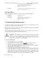
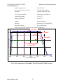
DC Current (A)
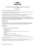
The open circuit voltage of PV modules depends on the cell temperature and the solar
irradiation. The highest open circuit voltage occurs when the PV modules are at the
coldest temperature and in bright sun. (See the following figure – Fig. 9)
8
6
at 50 deg C
4
at 20 deg C
2
at -20 deg C
0
0
5
10
15
20
25
30
Voltage (VDC)
Fig. 9 Example representative PV module voltage –
current characteristic at various cell temperatures
Because the PV modules also have a reduction in voltage at high cell temperatures, you must make
sure the MPP voltage of the strings will not drop below the minimum inverter DC input voltage of
325V DC in very hot temperature conditions.
Both the maximum open circuit voltage (OCV) when at cold extreme and minimum MPP voltage
when at hot extreme can be calculated for a PV module using its specification sheet. PV module
string sizing can then be used to determine how many modules can/should be used in a string.
DOC-020099 rev 041
34
PVI 60KW, PVI 82KW, PVI 95KW
Installation and Operation Manual
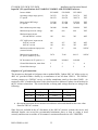
Input DC (PV) specifications for PVI 60KW, PVI 82KW AND PVI 95KW inverters
Inverter Model
PVI 60KW
PVI 82KW
PVI 95KW
Operating voltage range (power)
LV option
305-570
290-570
305-570
290-570
305-570
290-570
VDC
VDC
Input voltage MPP range
LV option
312-500
297-480
312-500
297-480
312-500
297-480
VDC
VDC
Max continuous power range
340-480
340-480
340-480
VDC
Maximum open circuit voltage
600
600
600
VDC
Maximum input current
208 and 480VAC versions
190
244
285
ADC
CEC eligible max. input current
208VAC version
480VAC version
190
190
247
260
285
285
ADC
ADC
Maximum continuous input power
(inverter limited)
63
87
100
kW DC
Maximum recommended
PV power (modules @ STC)
50-70
70-90
80-115
kW DC
DC disconnect for PV positive (+)
included
included
included
Ground fault detection, must detect
2
2
2
A
Ground fault interrupt
2
2
2
A
Output to AC grid connection:
The inverters are designed to feed power into a standard 60Hz, 3-phase 480V AC utility service or
480V AC provided within a facility by a transformer of not less than 150kVA. The 208VAC
versions connect to a 208VAC service or facility transformer rated no less than 150kW. As
required by NEC (Canadian Electrical Code), there must be a dedicated 3-phase circuit breaker for
the PV inverter connection. This circuit breaker or fusing (and wiring) must have a rating of the
following:
•
208 VAC*
480 VAC
PVI 60KW
250 A
125 A
PVI 82KW
300 A
150 A
PVI 95KW
350 A
150 A
600 VAC
110 A
125 A
125 A
the current protection device must not exceed these values and should be this exact value.
Same for 240VAC versions
Since fuses are included in the AC disconnect of the 480VAC inverter versions, the service and
dedicated breaker can exceed the recommended minimums above as long as wiring is sized
correctly and does not exceed the AC disconnects’ maximum allowed wire size: 250KCMIL.
DOC-020099 rev 041
35
PVI 60KW, PVI 82KW, PVI 95KW
208 VAC
240 VAC
480 VAC
600 VAC
Installation and Operation Manual
PVI 60KW
188-228 V
212-264 V
425-528 V
531-660 V
PVI 82KW
188-228 V
212-264 V
425-528 V
531-660 V
PVI 95KW
188-228 V
212-264 V
425-528 V
531-660 V
Output (AC) specifications for PVI 60KW, PVI 82KW AND PVI 95KW Inverter:
Inverter Voltage
208
240
480
600
VAC
Nominal and Maximum output power PVI 60KW 60
(and CEC eligible output power PVI 82KW 83
for 208 and 480VAC versions) PVI 95KW 95
60
83
83
60
83
95
60
83
95
kW AC
kW AC
kW AC
Operating voltage range
188 - 228
212-264
Operating voltage adjustability
VAC
50-120%
Default over/under voltage trip points and times
per IEEE Std 1547-2003, Table 1
Over / under voltage trip time adjustability
0.16 – 30
Voltage measurement accuracy
seconds
+/- 2 %
Default Operating frequency range
Operating frequency adjustability
59.8 - 60.5
57.0 - 60.5
Default over / under frequency trip points and times
Hz
Hz
per IEEE Std. 1547-2003, Table 2
Over / under frequency trip time adjustability
0.16 – 300
Frequency measurement accuracy
Maximum Output Current
425-528 531-660
seconds
+/- 0.1
PVI 60KW
PVI 82KW
PVI 95KW
166
229
261
147
204
230
Hz
73
100
115
Peak short circuit output current
60
Arms
80
Arms
92
Arms
7
kA
Total Harmonic distortion (THD, @ full power)
<4
%
Power Factor
98
%
Anti-islanding protection
per UL1741 / IEEE1547
AC disconnect, 3-phase
included
Over current protection
inverter limited
Short circuit protection
per UL1741/IEEE1547
Surge test
per UL1741/IEEE1547
and NY SIR
Inverter peak Efficiency (50-75% load)*
(complete integrated unit with transformer)
95.5
95.7
96.5
96.6
%
CEC Weighted Efficiency (fan forced on 100% of the time)
94.5
N/A
95.5
N/A
%
DOC-020099 rev 041
36
PVI 60KW, PVI 82KW, PVI 95KW
Other specifications:
Installation and Operation Manual
Ground fault protection
2005 NEC 690.5
DC sub-combiner-fuse enclosure
(Optional)
35A-200A fuses available
2-48 pole, NEMA 3R, TVSS
DC Disconnect (Integral)
Break load rated, NEMA 3R
Ambient Temperature
-25o to 50o C
Storage Temperature
-25o to 50o C
Cooling
Forced Convection
Enclosure
rainproof per UL1741/IEEE1547
Enclosure-electronics
IP-62 (sealed design)
*Does not include MPP tracking and other transitory phenomena.
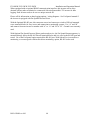
PVI 95KW
90
PVI 82KW
.
PVI 60KW
AC Power (kW)
60
Standard “strike”
voltage 400V
30
0
300
350
400
450
500
550
600
DC (PV) Voltage (VDC)
Fig. 10 AC Output power of PVI 60KW, PVI 82KW and PVI 95KW inverters
DOC-020099 rev 041
37
PVI 60KW, PVI 82KW, PVI 95KW
Installation and Operation Manual
PVI 95KW
90
PVI 82KW
.
PVI 60KW
AC Power (kW)
60
30
LV-“strike” voltage
380V
0
250
300
350
400
450
500
550
600
DC (PV) Voltage (VDC)
Fig. 10.1 AC Output power of PVI 60KW, PVI 82KW and PVI 95KW inverters (Low
Voltage option)
DC Amperes (ADC)
300
250
200
150
100
50
0
300
350
400
450
500
550
600
DC (PV) Input Voltage (VDC)
Fig. 11 Example maximum continuous DC current input for PVI 82KW
DOC-020099 rev 041
38
PVI 60KW, PVI 82KW, PVI 95KW
Installation and Operation Manual
Overall Efficiency DC (PV)
to AC (3-phase) %
100
90
80
70
60
50
0
30
60
90
AC Power (kW AC)
Fig. 12 PVI 95KW efficiency plot at 390VDC input and 25C ambient temperature
(efficiency values were measured with a 3% accurate power meter setup and do not
include any losses caused by long wires and transitory phenomena)
Pin assignment RS232 / RS485 (optional)
1
2
3
4
5
6
7
8
RS232 TXD
RS232 RXD
RS232 GND
RS485 A (optional)
RS485 GND (optional)
RS485 B (optional)
RS485 GND
NC
(front view of 8-pin communication connector on
inverter, and back of mating connector)
Mating AMPSEAL 8-pin connector, Tyco part#: 776286-1
AMSEAL crimp contact, Tyco part#: 770854-3
Warning:
RS232 and RS485 (standard on all inverters ordered after July 15, 2008) share the same serial port
and only one can be used at one time! Both cannot be used at once. RS-485 must be ordered as an
option and the inverter comes wired for 485 if it is ordered. The port can be toggled back and
forth from 485 to 232 with PC software from the factory and a 232 serial cable.
DOC-020099 rev 041
39
PVI 60KW, PVI 82KW, PVI 95KW
Installation and Operation Manual
When equipped with an optional RS485 communication interface, this inverter can be daisychained with any other residential or commercial Solectria Renewables’ PV inverter for data
logging. Each inverter needs to be set to a unique network ID.
Please call for information on data logging options / wiring diagrams. See Fat Spaniel manual if
the inverter is equipped with Fat Spaniel Inverter Direct.
With the Optional RS-485 port, this connector comes in a harness pre-wired to DIN-rail mounted
screw terminal blocks for easy access and connection to monitoring systems. Use “A” and “B”
and connect from one inverter to another with “A” to “A” and “B” to “B”. Ground is not currently
used.
With Optional Fat Spaniel Inverter-Direct product and service, the Fat Spaniel Internet gateway is
mounted directly above the RS-485 Din-rail terminal blocks and it is wired to the RS-485 port and
tested. Use of the Fat Spaniel option required the RS-485 port. With SolrenView inverter-direct
monitoring or revenue-grade with inverter-direct monitoring option, RS-485 is also used.
DOC-020099 rev 041
40
PVI 60KW, PVI 82KW, PVI 95KW
Installation and Operation Manual
Appendix A – PVI 60KW, PVI 82KW
and PVI 95KW Data Sheet
http://www.solren.com/downloads/PVI_60KW_PVI82KW_PVI95KW.pdf
Appendix B - Contact Information
Solectria Renewables LLC
360 Merrimack Street, Building 9
Lawrence, Massachusetts, 01843
USA
Tel: 978.683.9700
Fax: 978.683.9702
Email: [email protected]
Website: www.solren.com
Authorized Distributors/Dealers/Installers/Designers:
See website for complete and updated listing: www.solren.com
Specific Link: http://www.solren.com/contact/dist.htm
DOC-020099 rev 041
41
PVI 60KW, PVI 82KW, PVI 95KW
Installation and Operation Manual
Appendix C – UL1741 IEEE 1547 Authorization Letter to Mark Product:
DOC-020099 rev 041
42