1
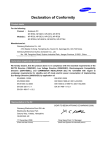
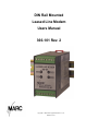
DIN Rail Mounted
Leased Line Modem
Users Manual
366-101 Rev. 2
Copyright © 2008 Miille Applied Research Co., Inc.
Houston, Texas
This page is left blank intentionally
366-101
Page i
TABLE OF CONTENTS
LIST OF FIGURES ............................................................................................... i
General ......................................................................................................................... 1
Physical Description ................................................................................................... 1
1.3
Indicators ..................................................................................................................... 1
1.4
Specifications .............................................................................................................. 2
1.4.1 Physical....................................................................................................................... 2
1.4.2 Operating Environment ............................................................................................. 2
1.4.3 Power Requirements .................................................................................................. 2
1.4.4 LED Indicators ........................................................................................................... 2
1.4.5 Connections ................................................................................................................ 2
1.4.6 Operating Modes and Speeds .................................................................................... 2
1.4.7 PTT (Push-To-Talk) output....................................................................................... 2
1.4.8 Part Numbers .............................................................................................................. 2
2.1 General ............................................................................................................................... 3
2.2 RS232 Connections ........................................................................................................... 3
2.3 Phone Line Connections ................................................................................................... 3
2.4 Power Connections............................................................................................................ 3
2.5 PTT (Push-to-Talk) Output............................................................................................... 4
POSITION ................................................................................................................... 4
SIGNAL NAME ......................................................................................................... 4
2.6 Operating Mode................................................................................................................. 4
2.7 PTT Enable ........................................................................................................................ 5
2.8 Transmit Level................................................................................................................... 5
1.1
1.2
LIST OF FIGURES
Table 1 TS2 Pin Assignments................................................................................................. 3
Table 2 TS1 Pin Assignments................................................................................................. 4
Table 3 Operating Modes ........................................................................................................ 4
Table 4 SW1 PTT Enable and Transmit Level...................................................................... 5
Copyright © 2008 Miille Applied Research Co., Inc. Houston, Texas
Page i
366-101
Page 1
Introduction
1.1 General
The Miille Applied Research Co., Inc. (MARC) Model 366-101 is a full-function DC
powered FSK (Frequency Shift Keyed) Leased Line modem that mounts on a standard
DIN-rail and provides data communication with other Bell and CCITT compatible
modems. The modem is suitable for use with standard voice grade leased telephone
circuits, private dedicated wiring and many radios. This modem provides convenient
terminal compression screw hook-up and clearly marked, easily accessible switches for
quick and accurate operating mode configuration. The modem is ideal for connecting a
PLC or other intelligent device for remote programming or data collection.
1.2 Physical Description
The 366-101 is a small DIN-rail mountable unit just 1.75” wide, 3.0” high and 4.1” deep
as shown in the photo below. It has two 8 position pluggable terminal strips for easy
hook-up and a removable door for easy access to the configuration switches. Four LED
indicators on the front panel provide easy monitoring of data communication activity.
1.3 Indicators
The 366-101 has four LED indicators
mounted on the front panel. TXD and
RXD LEDs light when the modem is
sending or receiving data. The DCD
LED will be on when the modem
detects a Carrier signal from another
(transmitting) modem. The RTS LED
monitors the state of the RTS input.
If RTS is on, the modem will turn on
its transmitter and after a short delay
(RTS-CTS Delay), will be ready to
transmit data.
Copyright © 2008 Miille Applied Research Co., Inc. Houston, Texas
Page 1
366-101
Page 2
1.4 Specifications
1.4.1 Physical
DIN rail mountable unit 1.75”W X 3.0”H X 4.1”D
1.4.2 Operating Environment
0°to 60° Celsius
1.4.3 Power Requirements
24 VDC at 40 ma
1.4.4 LED Indicators
Provide status of the following signals TXD, RXD, DCD and RTS
1.4.5 Connections
Two 8-pin pluggable terminal strips.
1.4.6 Operating Modes and Speeds
Asynchronous or Synchronous operation at speeds up to 1200 baud over
unconditioned telephone lines. Bell 202, Bell 103, CCITT V.21 and CCITT V.23
compatibility. Operating mode is switch selectable. Two wire half duplex or four
wire full duplex operation is user selectable.
1.4.7 PTT (Push-To-Talk) output
PTT dry contact closure for control of a radio transmitter. Closed when modem is
ready to send data.
1.4.8 Part Numbers
366-101
Copyright © 2008 Miille Applied Research Co., Inc. Houston, Texas
Page 2
366-101
Page 3
Installation
2.1 General
The 366-101 modem is very easy to install and set up. Remove the modem from its
protective antistatic bag and simply snap it onto a standard symmetrical EN 50 002
(35mm) mounting rail. If you need to remove the modem from the mounting rail use a
flat screwdriver to retract the red mounting tab.
2.2 RS232 Connections
All RS232 signals are terminated on TS2, an 8 position pluggable terminal strip. TS2 is
the terminal strip located on the side of the modem on the same side as the option
selection switch access door. It is on the bottom of the case if the modem is mounted so
that you can read the front label.
POSITION
1
2
3
4
5
6
7
8
SIGNAL NAME
DCD
DSR
CTS
DTR
RDATA
RTS
TDATA
GND
DIRECTION
Output
Output
Output
Input
Output
Input
Input
Reference
Table 1 TS2 Pin Assignments
2.3 Phone Line Connections
Telephone line connections are made on TS1, the 8 position pluggable terminal strip
located opposite the option selection switch access door. It is on the top of the case if the
modem is mounted so that you can read the front label. There are four wires to connect
named TX+, TX-, RX+ and RX-. For two wire applications, connect a jumper between
the TX+ and RX+ pins and the TX- and RX- pins. The modem does not provide a
modular jack because it is used in harsh industrial environments where the standard RJ11 modular jack is not reliable. If you require a modular connection, you should purchase
a standard wall mount modular adapter available from any hardware store.
2.4 Power Connections
The modem is DC powered. The operating range is 18-36 VDC. You must pay particular
attention to the input polarity. The modem will be damaged if the voltage polarity is
reversed. Connect the Positive side of the DC supply to Pin 7 and the Negative side to Pin
8 on TS1
Copyright © 2008 Miille Applied Research Co., Inc. Houston, Texas
Page 3
366-101
Page 4
2.5 PTT (Push-to-Talk) Output
The modem provides a PTT (Push-to-Talk) contact output for optional control of a radio
transmitter. The PTT output is a dry (potential free) contact closure that will be closed
when the modem RS232 RTS input is active. Connect the PTT wires to Pin 1 and Pin 6
of TS1.
POSITION
1
2
3
4
5
6
7
8
SIGNAL NAME
PTTRXTXTX+
RX+
PTT+
+24VDC
DC RETURN
Table 2 TS1 Pin Assignments
2.6 Operating Mode
The modem operating mode is selected using a 5 position DIP switch. Remove the option
door for access to this switch. The following table defines the modem operating mode
switch selections.
SW 2
Pos. 1 2 3 4 5
11111
01111
10111
00111
11011
01011
10011
00011
11101
11001
10001
00001
10110
00110
10010
00010
11100
Operating Mode
Bell 103 Originate 300 bps Full Duplex
Bell 103 Answer 300 bps Full Duplex
Bell 202 1200 bps, Half Duplex
Bell 202 1200 bps, Half Duplex with equalizer
CCITT V.21 Originate 300 bps Full Duplex
CCITT V.21 Answer 300 bps Full Duplex
CCITT V.23 Mode 2 1200 bps Half Duplex
CCITT V.23 Mode 2 1200 bps Half Duplex with equalizer
CCITT V.23 Mode 1 600 bps Half Duplex
CCITT V.23 Mode 1 600 bps Half Duplex with SCTO
CCITT V.23 Mode 2 1200 bps Half Duplex with SCTO
CCITT V.23 Mode 2 1200 bps Half Duplex w/Equalizer and SCTO
Bell 202 1200 bps Full Duplex with SCTO
Bell 202 1200 bps Full Duplex w/Equalizer and SCTO
CCITT V.23 Mode 2, 1200 bps Full Duplex
CCITT V.23 Mode 2 1200 bps Full Duplex with equalizer
CCITT V.23 Mode 1 600 bps Full Duplex
Table 3 Operating Modes
Copyright © 2008 Miille Applied Research Co., Inc. Houston, Texas
Page 4
366-101
Page 5
2.7 PTT Enable
The PTT enable relay can be turned ON and OFF using switch SW1 position 1. If this
switch is ON the PTT relay will operate when the modem RTS input is active. If this
switch is OFF then the PTT relay will never operate.
2.8 Transmit Level
Switch 1, positions 2 through 9 are used to select the modem transmit level. Using these
switches you can adjust the modem transmit levels between +2 and –12 dBM as shown in
the table below.
SWITCH #
1
2
3
4
5
6
7
8
9
FUNCTION
PTT Enable
+2 dBm Transmit Level
0 dBm Transmit Level
-2 dBm Transmit Level
-4 dBm Transmit Level
-6 dBm Transmit Level
-8 dBm Transmit Level
-10 dBm Transmit Level
-12 dBm Transmit Level
Table 4 SW1 PTT Enable and Transmit Level
Other transmit values can be obtained by closing more than one switch at a time.
Copyright © 2008 Miille Applied Research Co., Inc. Houston, Texas
Page 5