1
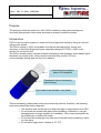
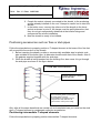
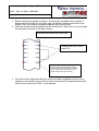
INSTALLATION & MAINTENANCE MANUAL
FOR FLUE RENOVATION SYSTEM - FitFire &
Fitfireplus
Edition
Revision
Approved by
Written by
1
1.2
C. Lezzi
C. Lezzi
Date
14/02/2011
Code
01_01__Manuale_inst_Fitfire-plus
Page
12
File Name
01_01.2_Manuale inst_ FitFire_.docx
01_01.1_Manuale_inst_FitFire
Ed. 01
Rev. 1.2 Date 14/02/2011
Page 2 of 12
Table of contents
TABLE OF CONTENTS ................................................................................................................................................. 2
PURPOSE.......................................................................................................................................................................... 3
INTRODUCTION ............................................................................................................................................................ 3
USE .................................................................................................................................................................................... 4
GOOD OCCUPATIONAL HEALTH PRACTICES: ................................................................................................... 4
INSTALLATION .............................................................................................................................................................. 4
LIST OF MATERIALS AND EQUIPMENT NEEDED FOR PROPER INSTALLATION .................................................................... 6
PREPARATION OF BOILER ROOM AND ROOF. .................................................................................................................... 6
HOW TO INSERT THE SHEATH: ............................................................................................................................... 7
POSITIONING ACCESSORIES SUCH AS TEES OR STUB PIPES ........................................................................ 8
HOW TO INFLATE THE SHEATH: .......................................................................................................................... 10
MAINTENANCE ............................................................................................................................................................ 12
01_01.1_Manuale_inst_FitFire
Ed. 01
Rev. 1.2 Date 14/02/2011
Page 3 of 12
Purpose
The purpose of this document is to offer FitFire installers a clear and unambiguous
document that specifies instructions and steps to properly install the system.
Introduction
FitFire is an innovative system to renew old flues of gas-fired boilers by lining an old duct
using a new sheath.
The FitFire system is 100% not suitable for solid fuel burning boilers, stoves and
chimneys, in fact Beca Engineering has especially designed HT1000, a 100% inert
system, for this kind of fuel.
The FitFire sheath mainly consists of thermo-hardening, heat-resistant, water-based resins
that does not contain furan, furfuryl alcohol and antimony trioxide. FitFire is
environmentally friendly and not toxic for installers.
Interlocking tube-shaped
sleeve for installation
Fibreglass & thermo-hardening
resins prepeg
Liner made of special fabric, non elastic
Thermo-hardening, water-based resins are intrinsically reactive; therefore, the following
instructions should be strictly observed:
• The product must not be stored to direct sunlight or temperatures over 30°C.
• Do not wash the sheath with water before installing. Otherwise, it can get
damaged and no longer suitable for installation. Only once polymerised can
the sheath get in contact with water.
• Do not wet the sheath with any other kind of liquids before installing it. Store
in a dry place.
• Do not store longer than 3 weeks at 15°-17°C.
01_01.1_Manuale_inst_FitFire
Ed. 01
Rev. 1.2 Date 14/02/2011
Page 4 of 12
Use
FitFire is suitable for conveying combustion gases of gas and condensing boilers outdoors.
The system features the characteristics below and has been certified as compliant to
them:
• N1 negative pressures
• P1 positive pressures
• T300 maximum temperature class
• Condensate present conditions
It is highlighted that the FitFire system is category O soot-fire resistance.
To renew flues for solid and liquid fuel heating appliances it is advisable to use HT1000, a
100% inert system, A1 fire reaction class and category G soot-fire resistance.
Good Occupational Health Practices:
•
•
•
Wear suitable gloves when handling/working with the sheath
If your hands are dirty with the product, do not use them to eat.
Strictly observe the instructions specified in the MSDS.
Installation
Video inspect the status of existing flues so that you can successfully apply the sheath.
•
•
The flue interiors should not be rough, show blunt points or any other defect that
may damage the sheath while it is being inserted.
Flues should not have 90° bends; only two 45° bend s or two 30° bends
maximum are allowed.
01_01.1_Manuale_inst_FitFire
Ed. 01
Rev. 1.2 Date 14/02/2011
Page 5 of 12
•
The interiors should not show any water leaks or drips; otherwise, the sheath
itself and the polymerisation are compromised.
01_01.1_Manuale_inst_FitFire
Ed. 01
Rev. 1.2 Date 14/02/2011
Page 6 of 12
List of materials and equipment needed for proper installation
The following materials and equipment are needed for installing
the sheath properly:
•
•
•
•
•
•
•
•
•
•
FitFire sheath of suitable size and diameter for the flue to
be renewed. In general it should be around 2 m longer
than the existing flue.
Sockets of suitable diameter for the sheath to be installed
Check that the pressure gauge on the upper socket works
properly.
Socket clamps and protective rubber rings (at least 3 per socket)
As many steam boilers as needed for sheath polymerisation. Diesel fuel and
distilled water as required for proper boiler functioning.
Steam suitable pipes and fittings to connect the boiler sockets.
Tripods to anchor the sheath to the roof.
Assorted supporting devices such as assorted tools and condensate collection
bucket.
Digital thermometer, if necessary, to check sheath temperature at polymerisation.
Standard-compliant grinders to cut sheath at both ends once the polymerisation
process finishes.
Preparation of boiler room and roof.
It is of utmost importance to properly prepare the boiler room for a successful installation.
a) Boiler room:
• Work so that the existing flue is easily reached; the mouth through which
the FitFire sheath will be introduced should be wide enough to facilitate
insertion operations. If the already existing flue has a union tee, use a
new tee fitting for the sheath to go through. It is advisable that the
insertion mouth be as straight as possible, thus avoid 90º accesses, so
that the sheath can expand/extend easily when inflated.
b) Roof:
• Position the sheath anchoring system at the mouth; extend tripod legs
according to the sheath diameter and the existing flue mouth.
• Put a tensioning cable through the existing flue up to the lower mouth.
This cable will be needed when the sheath is inserted.
01_01.1_Manuale_inst_FitFire
Ed. 01
Rev. 1.2 Date 14/02/2011
Page 7 of 12
How to insert the sheath:
Inserting the sheath is a highly delicate, key operation and the success of a proper
installation totally depends on it. Strictly follow the steps below. A sheath can be inserted
either by pulling it from bottom to top or by lowering it from top to bottom.
• The first solution is often used when the sheath is heavy and has proven
useful when it is not safe or too difficult to work on the roof.
• The second solution is used in less complex and demanding cases. Anyway,
the installer should be able to assess each case and choose the most
suitable solution for the flue to be renewed.
• While the sheath is being inserted (by either method above), pay utmost
attention so that the sheath is as straight as possible, does not get coiled or
twisted in a ‘candy-wrapper’-like manner.
• While the sheath is being inserted, always follow it through the duct and fold
it to form a U-shape.
Caution. Do not use cold or hot water trying to soften the sheath. Under no
circumstances can a wet sheath be used as it is irreparably damaged.
Should this occur, the warranty shall be rendered void.
•
Follow the steps below:
1. If you are inserting the sheath from bottom to top, fasten tight the
sheath to the cable already fitted inside the flue at the boiler room.
2. The installer on the roof is to operate the winch (it is advisable to do
so at a low speed) or pull the sheath slowly by hand.
3. The installer in the room must always follow the sheath through the
duct and fold it to form a U-shape.
4. When the end of the sheath reaches the roof, insert the socket plus
the pressure gauge needed to inflate the sheath.
5. Fit the pipe clamps (3 minimum) to fasten the sheath to the socket.
Also fit as many rubber rings as needed between clamp and sheath; if
these rings are used the sheath is not ‘pinched’ and the internal plastic
sleeve is not damaged.
Caution: Before fitting the clamp around the sheath already on the socket,
carefully fold the excess sheath around the socket so that no wrinkles are
formed when the clamps are tightened.
01_01.1_Manuale_inst_FitFire
Ed. 01
Rev. 1.2 Date 14/02/2011
Page 8 of 12
6. Couple the socket, already connected to the sheath, to the anchoring
system already installed on the roof. Always be careful not to twist the
sheath.
7. In the boiler room, connect the other end of the sheath to the lower
socket as shown in point 5. All clamps must be well tightened so that
they do not get unexpectedly detached at the inflation stage and
compromise the whole installation.
8. Now the sheath is ready to be inflated.
Positioning accessories such as Tees or stub pipes
Follow the steps below to properly position a T-shaped element at the base of the flue that
will connect the fumes duct to the sheath:
1. Before inserting the sheath, position a commercially available steel or plastic stub
pipe suitable for the boiler type; its diameter should match that of the sheath. Also fit
the gaskets supplied together with the stub pipe.
2. While the sheath is being inserted into the existing flue, also cause it to go through
the stub pipe as shown in the figure below.
STUB PIPE POSITIONING
Sealing gaskets for a steel or
plastic stub pipe
Due to the vapour injected into it, the
thermo-hardening sheath expands against
the sealing gaskets. Once the
polymerisation process finishes, the new
composite flue is fully adhered to the
gaskets and the result is perfect sealing.
Only after all the steps described are carried out and completed can you install on the stub
pipe a T-shaped element or condensate collection accessories.
Positioning intermediate T-shaped elements:
Follow the steps below to properly position intermediate T-shaped elements.
01_01.1_Manuale_inst_FitFire
Ed. 01
Rev. 1.2 Date 14/02/2011
Page 9 of 12
1. Before inserting the sheath, position a commercially available steel or plastic Tshape element suitable for the boiler type; its diameter should match that of the
sheath. Also fit the gaskets supplied together with the stub pipe.
2. While the sheath is being inserted into the existing flue, also cause it to go through
the stub pipe as shown in the figure below.
T-SHAPED ELEMENT POSITIONING
Sealing gaskets for a steel or
plastic Tee
Due to the vapour injected into it, the thermohardening sheath expands against the sealing
gaskets. Once the polymerisation process finishes,
the new composite flue is fully adhered to the
gaskets and the result is perfect sealing.
3. Only after all the steps described are carried out and completed can you cut an
opening in the sheath (using a hollow cutter) matching the T-shaped element and
connect the fumes duct to this T or as planned.
01_01.1_Manuale_inst_FitFire
Ed. 01
Rev. 1.2 Date 14/02/2011
Page 10 of 12
How to inflate the sheath:
You must give this step your utmost attention. All equipment such as pressure
gauges that detect and read pressure at the upper socket must work properly. Make
sure that boilers work properly and use distilled water.
If the pressure gauge does not work properly, pressure may go beyond the
maximum working value allowed and so the sheath can get irreparably damaged.
Pressure must be checked throughout the inflation procedure.
1. Take the vapour pipe coming from the gyser generator nearby and
screw in the fitting to the lower socket on the mouth in order to inject
vapour
2. Switch on the vapour generator as described in the user manual for
the Gyser generator
3. Cause the vapour maximum temperature on the generator to reach
150°C.
4. Once the generator is under pressure and has reached the desired
temperature, open the cock about ¼ of a turn to slowly start inflating
the sheath.
5. Once the pressure starts to expand, take the inflation pressure to 0.15
bar:
01_01.1_Manuale_inst_FitFire
Ed. 01
Rev. 1.2 Date 14/02/2011
Page 11 of 12
•
•
•
First, fully open the vapour vent cock at the upper socket
Open the vapour cock a little more, up to ¾ of a turn
Adjust the vent cock at the upper socket and check pressure
level on the pressure gauge on the upper socket.
CAUTION: Follow these rules so that heat is not disperse:
• If there are gaps or interspaces between the sheath and the
existing flue, put some cloth either from the boiler room side
or the roof side. This will prevent a constant air flow through
the interspaces that transfers heat to the sheath.
• Never use vapour pipes longer than 10 m from the sheath to
the generator, especially in winter. In case you do, insulate
pipes so that not much heat is lost before they reach the
sheath.
6. Keep the pressure indicated above until the sheath starts to have a
‘gummy’ consistency. When this occurs, take the pressure indicated
by the pressure gauge to 0.18 bar and keep it until the resin is
completely polymerised (about 2h). Always make sure that the resin
has hot hardened by checking it is fully hard and not 'sticky'; it should
be firm when touched or hammered manually or by using a durometer
with indentor.
7.
CAUTION: The polymerisation time mentioned is indicative only under
normal conditions. This time normally depends on several factors:
• External temperature
• Boiler proper functioning: Use of distilled water, clean combustion
chamber
• Moisture at the existing duct.
Therefore, make sure that the sheath has hardened properly by touching it
or by using a durometer with indentor.
CAUTION: Do not turn off the boiler if the sheath has not polymerised since
if it is hot and still soft, once it cools off, it may seem to be hard when it is
not, and therefore proper functioning is compromised. That is the reason
why you should wait until it hot hardens.
8. Once the sheath has completely polymerised, use a grinder to cut it
on the roof side below the socket on the circular section, and cut the
insulation at the centre, above the socket.
01_01.1_Manuale_inst_FitFire
Ed. 01
Rev. 1.2 Date 14/02/2011
Page 12 of 12
9. Remove the internal plastic sleeve from the polymerised sheath. If you
are installing a Fitfireplus system, do not attempt removing the plastic
sleeve from the sheath.
10. Now the flue is totally renewed.
Once you finish installing the system, carry out the P1 or N2 tightness test according to the
intended use of the flue and the requirements of the UNI 10845:2000 standard.
Maintenance
Maintaining a FITFIRE system implies cleaning the flue whenever necessary using plastic,
not metal, brushes so that the system is not damaged. It also includes checking the
system for proper condition regularly.