1
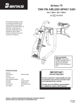
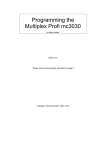
User Manual for MO-CON501 CNC Pendant Controller
Rev.1.0
The content in this manual has been carefully prepared and is believed to be
accurate, but no responsibility is assumed for inaccuracies.
Motion Control Products Limited reserves the right to make changes without
User’s Manual
For
further notice to any products herein to improve reliability, function or design.
Motion Control Products Limited does not assume any liability arising out of the
application or use of any product or circuit described herein; neither does it
convey any license under its patent rights of others.
MO-CON501
Motion Control Product’s general policy does not recommend the use of its
CNC Pendant Controller
the product may directly threaten life or injury. According to Motion Control
products in life support or aircraft applications wherein a failure or malfunction of
Product’s terms and conditions of sales, the user of Motion Control Product’s
products in life support or aircraft applications assumes all risks of such use and
indemnifies Motion Control Products Limited against all damages.
Revision 1.0 (July 2009)
Attention: Please read this manual carefully before using the pendant controller
Motion Control Products Ltd
Copyright © 2009 Motion Control Products Ltd. All rights reserved.
All data subject to change without notice in advance
11-15 Francis Avenue
Bournemouth, Dorset, UK BH11 8NX
Tel.: +44 (0)1202 599922
Fax: +44 (0)1202 599955
E-mail: [email protected]
www.motioncontrolproducts.com
User Manual for MO-CON501 CNC Pendant Controller
Rev.1.0
Contents
Table of Contents
1. CAUTION........................................................................................................... 1
2. INTRODUCTIONS ............................................................................................. 1
2.1 Description ................................................................................................... 1
2.2 Main Features .............................................................................................. 1
2.3 Technical Specifications ............................................................................... 2
2.4 Connecting Board Wiring Diagrams............................................................. 3
3. FUNCTIONS AND SETTINGS .......................................................................... 3
3.1 Button Functions .......................................................................................... 3
3.2 Compound Buttons ...................................................................................... 5
3.3 Basic Settings and Advanced Settings ........................................................ 5
3.3.1 Machine Setup ...................................................................................... 6
Pulse Equivalent......................................................................................... 7
Table Size ................................................................................................... 8
Motor Direction ........................................................................................... 8
Home Setup................................................................................................ 9
Spindle Setup ........................................................................................... 11
Voltage Setup ........................................................................................... 12
C.A.D. Thickness...................................................................................... 13
Screw Interspaces .................................................................................... 14
3.3.2 Auto Process (Auto Pro) Setup ........................................................... 15
Linear Acceleration ................................................................................... 15
Curve Acceleration ................................................................................... 16
G-Code Read Setup ................................................................................. 16
3.3.3 System Setup ...................................................................................... 17
Function Setting........................................................................................ 17
Power-Off Protection ................................................................................ 17
Set Home Switch ...................................................................................... 17
Go Home types......................................................................................... 17
Inner Formatting ....................................................................................... 18
Input Self-check........................................................................................ 19
Output Self-check ..................................................................................... 19
Buttons Check .......................................................................................... 19
System Auto Update................................................................................. 19
3.3.4 Advanced Process (Advanced Pro) Setup.......................................... 20
Multiple Setup .......................................................................................... 20
File Maintenance...................................................................................... 21
3.3.5 Version View ....................................................................................... 22
4. HOW TO USE THE CONTROLLER ............................................................... 22
4.1 Power On ................................................................................................... 22
4.2 Working Co-ordinate.................................................................................. 23
4.3 Travel Speed Settings................................................................................ 23
4.4 Moving In Manual Mode ............................................................................ 24
4.5 Spindle Control .......................................................................................... 25
4.6 Cutting Adjustment Device (C.A.D.) .......................................................... 26
4.7 Running a CNC programme ...................................................................... 27
4.8 Running a Machine.................................................................................... 28
4.9 Resume Machining .................................................................................... 29
4.10 Changing the Feed and Speed On the Fly .............................................. 29
4.11 Advanced Process ................................................................................... 30
4.11.1 Segment Process .............................................................................. 30
4.11.2 Multiple Process ................................................................................ 31
4.11.3 Segment-multiple Process ................................................................ 32
4.11.4 Mill Table ........................................................................................... 32
4.11.5 Tools Change .................................................................................... 33
APPENDIX .......................................................................................................... 34
TWELVE MONTH LIMITED WARRANTY ....................................................... 34
EXCLUSIONS.................................................................................................. 34
SHIPPING FAILED PRODUCT & OBTAINING WARRANTY SERVICE ......... 34
WARRANTY LIMITATIONS ............................................................................. 34
MO-CON501 Pendant Controller Installation Guide
Rev.1.0
Rev.1.0
2.3 Technical Specifications
1. CAUTION
•
Do NOT use this product in a strong magnetic field
•
Do NOT remove USB memory stick while running a programme
•
Protect it from water, moisture, dust and heat
•
Do NOT allow any liquid or other foreign body to get into the controller case
•
Do NOT open the cover, there are no maintainable parts inside
•
Be gentle when plugging in cables and USB memory stick
2. INTRODUCTIONS
2.1 Description
The MO-CON501 CNC Pendant Controller with built-in DSP (digital signal processor) reads
G-code or PLT programs (text file) and supports most Fanuc post processing from a USB
memory stick or its internal memory. The controller then converts it into output signals to the
motor drives. It also provides digital outputs to control a spindle motor (up to 16 speeds).
The MO-CON501 also accepts inputs from up to 3 limit switches and can supply power to 3
proximity sensors. It has an input to allow automatic setting of the Z-axis (after tool changes).
MO-CON501 CNC Pendant Controller Kit includes:
* 1x MO-CON501 Pendant Controller
* 1x USB cable
* 1x Connecting Board
* 1x SCSI cable
* 1x 1GB memory stick
2.2 Main Features
• Totally independent from PC platform;
• Easy to update system programme;
• Directly read files from USB memory
stick;
• Support high microstep which makes
precise and fast process possible;
• Easily process G-code or PLT file with a
large size;
• Support to run segments of a
programme;
• Good system and process file examining
function;
• Reliable data protection and recovery
function
Tel.: +44 (0)1202 599922
MO-CON501 Pendant Controller Manual
-1-
www.motioncontrolproducts.com
Specification
Contents
Specification
Contents
Working
Temperature
0°C to +70°C
Humidity
<90﹪
Output Voltage
5VDC
Power
Consumption
2W
Languages
English
Dimensions
156*110*38mm
Processor
160M DSP
Axes
3 axes
Display
LCD with 128 by 64
dot matrix, Back lit
screen
Communication
Terminals
USB terminal and USB
memory stick
File Format
G code, PLT files
(supports most Fanuc
post processing)
File Memory
128Mb Internal Memory, it
can support larger size files
because it reads directly
from a USB memory stick
(up to 1GB)
Help Function
On screen help
information and guide
Drive System
Step Motors or brushless
motors (pulse & direction)
Operating
Interface
Menu driven key pad
Interpolation
function
Polar and circular
interpolation
Spindle Control
Function
Yes (16 combination
binary out put)
Processing Data
Inspection
Function
Yes (display full
program on screen)
Multi Working
Coordinates
It has 10 working
coordinates (origin
points)
Copy Processing
Function
Yes
Tel.: +44 (0)1202 599922
Cutter
Adjustment
Function
System Data
Inspection
Function
Processing
Position
Adjustment
Function
Stop Point
Reprocessing
Function
Data protection
when power off
-2-
Yes (auto Z-axis set
function)
Yes (report programme
errors)
Yes (ability to adjust Z-axis
when stationary)
Yes (programme resume)
Yes (programme saves line
number when power is cut to
allow to continue from this
line)
www.motioncontrolproducts.com
MO-CON501 Pendant Controller Manual
Rev.1.0
MO-CON501 Pendant Controller Manual
Rev.1.0
2.4 Connecting Board Wiring Diagrams
Number “4” key + zeroing of X and Y axis origin
You need to connect the DSP board and the controller before starting running it properly.
Please refer to the supportive PDF document “MO-CON501 connecting Board Wiring
Diagram” for the details.
Number “5” key + Negative movement of X axis + Menu scroll-down
3. FUNCTIONS AND SETTINGS
Number “ 6” key + Negative movement of Y axis + decelerate process
speed + property selection in Menu
MO-CON501 CNC pendant controller is a motion control system which changes motion data
into related electronic signals which controls the movements of the 3 axes. This controller
reads CNC programme from a USB Memory stick which makes it is easy to use.
Number “ 7” key + Negative movement of Z axis, + decrease spindle
speed when running a programme (if set up)
3.1 Button Functions
Number “8” key + zeroing of Z axis origin
Number “9” key + move to Home
Number “0” key select High or Low speed when moving manually
decimal point key + manual spindle start-up / stop
Minus key + open menu , multi process state checking
Move to origin (i.e. Y0 X0) + select from menu + confirm inputs
Button
Mode this changes mode continues / distance / step, also displays speed
/speed ratio / line number when programme is running
Function
Number “1” key + Positive movement of X axis + Menu scroll-up
Select programme + pause when running + delete before entering new
data
Number “ 2” key + Positive movement of Y axis + accelerate process
speed + property selection in Menu
High/low speed parameter adjustment + stop programme when running +
exiting menu items + operating cancel
Number “ 3” key + Positive movement of Z axis + increase spindle
speed when running a programme (if set up)
Tel.: +44 (0)1202 599922
-3-
www.motioncontrolproducts.com
Tel.: +44 (0)1202 599922
-4-
www.motioncontrolproducts.com
MO-CON501 Pendant Controller Manual
Rev.1.0
MO-CON501 Pendant Controller Manual
Rev.1.0
3.2 Compound Buttons
There are some compound buttons for special applications. To use these, press the first
button and hold then press the second button, release the two buttons at the same time.
Their functions are as following:
1X
888.00
MANL
1Y
888.00
F0
1Z
88.00
Low
Continuous
Compound Button
Function
*** For more details of how to do “Home Operation”, please go to the section “Home Operating” on
Page 8.
Help information
+
The users can change and customise the parameters and settings under the Setup Menu if
needed. There are five Setting options in the menu: 1) CNC Machine Setup; 2)
+
+
Any number key, switch working co-ordinate (i.e. 1X, 1Y,
1Z to 9X, 9Y, 9Z)
Auto-process Setup; 3) System Setup; 4) Advanced Process Setup and 5)
software version.
Any number key, stop point resume (start a programme
from saved point)
Press
to enter the menu and the screen will show the following five
setting options:
Keys to open the Advanced Process Menu
+
+
MACHINE SETUP
AUTO PRO SETUP
SYSTEM SETUP
ADVANCED PRO SETUP
VERSION VIEW
Keys to activate the C.A.D function (Cutter Adjust
Device)
NOTES:
* If a single button is pressed, the function works when it is released.
** If compound button features are required, press the first button and then the second
one and release both at the same time.
After the Home Operation*** has been finished, the MO-CON501 controller will be in
Manual Mode.
-5-
or
.
3.3.1 Machine Setup
3.3 Basic Settings and Advanced Settings
Tel.: +44 (0)1202 599922
You can switch to different setup options by pressing
www.motioncontrolproducts.com
Machine setup parameters are specific to the machine hardware, such as drivers, I /O
terminals. If these parameters are wrong, it will lead to inaccurate movement and even
cause damage to the machine or injury to the operators. We strongly recommend machine
operators do NOT change these settings. If it is necessary to change the settings, please
seek advice from an expert before starting it.
Tel.: +44 (0)1202 599922
-6-
www.motioncontrolproducts.com
MO-CON501 Pendant Controller Manual
Rev.1.0
The chart below shows nine key fields that Machine setup includes: 1) Pulse Equivalent
Setup, 2) Table Size Setup, 3) Motor Direction Setup, 4) Home Setup, 5) Spindle Setup, 6)
Voltage Setup, 7) Output Pulse Setup, 8) C.A.D. Thickness Setup and 9) Screw Inner Space
Setup.
X Axis: 400.00
Y Axis: 400.00
Z Axis: 400.00
Machine Setup
Table Size
Motor Direction
to save the value. The cursor moves
Machine Size, mm
to the next line. If no change is required, press
X Axis: 1000.00
Y Axis: 1000.00
Z Axis: 1000.00
IF THE SETTING OF THE PULSE EQUIVALENT IS WRONG, THE SIZE OF THE
FINISHED ARTICLE WILL BE WRONG.
X Axis: -Dir
Y Axis: -Dir
Z Axis: -Dir
Motor Direction
Rev.1.0
When you are in “Pulse Equivalent” Setting, the cursor is on X-axis value. If it is necessary
to change it, input the value directly, then press
Equivalent, Pulse/mm
Pulse Equiv
MO-CON501 Pendant Controller Manual
to exit.
Table Size
Home Speed
Home Setup
Home Direction
Table size refers to the valid movement size of all 3 axes. Because the system uses the
table size as a soft limit, you should set the table size just under the size it really is.
Otherwise it could crash at the end of table stroke.
Spindle states
Spindle setup
When you are in “Table Size” setting, the cursor is on X-axis value. If it is necessary to
Lines State
Input Voltage
Voltage Setup
Output Voltage
change it, input the value directly, then press
to save the new value. The cursor
Least Pulse Width
Output Pulse
Pulse Voltage
moves to the next line. If there is no change required, press
to exit.
Display Pulse
C.A.D thickness (mm)
C.A.D. Thickness
0.00
If a CNC programme exceeds the table limits, the system will give a warning when it
checks the programme. If this occurs, you must change your programme, move your work
piece, or use a larger machine.
Screw Space (mm)
Screw Inter Space
X Axis: 0.00
Y Axis: 0.00
Z Axis: 0.00
Motor Direction
Motor Direction refers to the default direction of the motors on each axis. It gives you the
option of changing the direction without having to change the wires around.
Pulse Equivalent
Pulse Equivalent means the pulse number to move the axis per 1mm. Its unit is pulse/mm.
Pulse Equivalent= (360degree / Step angle) * (Microstep / Screw pitch)
This affects all other direction options. So if you change this, you may need to reset
them.
e.g. (360 / 1.8) * (4/ 5) = 160
Tel.: +44 (0)1202 599922
-7-
www.motioncontrolproducts.com
Tel.: +44 (0)1202 599922
-8-
www.motioncontrolproducts.com
MO-CON501 Pendant Controller Manual
Rev.1.0
MO-CON501 Pendant Controller Manual
Rev.1.0
home when in manual mode.
to access to this menu; use
Press
and
to scroll up and down and
Pressing
use
and
will zero Z creates an origin point which
the pendant controller uses when running a CNC programme.
to change the direction from + to -
Home Setup
will zero X & Y. Pressing
Pressing
will move the machine to the origin point for the current working
coordinate when in manual mode.
Home Function
“Home” is the machine origin. “Go to home” refers to moving all axes back to the machine
origin. Home position depends on home sensor. Normally there are 3 sensors on a 3-axis
machine. “Go to home” operation sets up the relationship between the machine and the
working co-ordinates. Many system function applications rely on this operation, such as stop
point save, power off reboot and so on.
1X 0.000, 1Y 0.000, 1Z 0.000
The MO-CON501 pendant controller can be set for use without the “Home feature” if
required.
It is good practice to home a machine after switching the power on.
Two Parameters: Home Speed and Home Direction
“Go to home” parameters include Home Speed and Home Direction. They can be
adjusted in Menu.
If you enter the menu by pressing
, please press
to exit and return to MANL
Home Speed refers to the speed of 3 axes back to home position. Normally the home speed
of the Z axis should be slower than X axis and Y axis.
as no changes are required here under normal use.
Home Operating
When the power is turned on, “Go to Home?” appears on the screen: this is a question
which will need to be answered by the operator:
Home Direction refers to which direction the axes go when moving back to home position. It
depends on the motor direction and Home sensor’s location.
Entering Menu, cursor is on “Machine Setup” option, press
Pressing
means “Yes”- the Z axis moves first; when the Z axis arrives at its home
position, the X and Y will also move to the home position.
Pressing
to enter the setting. Use
to move the cursor to “Home Setup” option, press
means “No”- the 3 axes do NOT move to their home positions.
the cursor is on “Home Speed” item automatically, press
Pressing any other KEY- Only the Z axis moves to home position; X and Y do NOT go home.
to enter the sub-menu,
to enter and set 3 axes
speed, detailed as following:
Home Speed (mm/min)
When the machine is moving to the home position, you can press the KEY
X Axis: 3000.00
to stop
Y Axis: 3000.00
Z Axis: 3000.00
“Homing”. The controller is now in Manual Mode. Pressing
Tel.: +44 (0)1202 599922
-9-
will move the machine to
www.motioncontrolproducts.com
Tel.: +44 (0)1202 599922
- 10 -
www.motioncontrolproducts.com
MO-CON501 Pendant Controller Manual
Rev.1.0
MO-CON501 Pendant Controller Manual
Rev.1.0
The spindle speed can be changed before or while a programme is running.
to delete the existing numbers and then
If you wish to change the settings, press
Move cursor to “Spindle Setup” item then press
use the number keys to enter the new settings. After finishing, press
to confirm and
save the new settings.
to enter. Then it shows the value of
spindle state, the default value is 2. (On and Off)
If you set this to 4 for example, you would have 4 speeds- Off, On at speed 1, On at speed 2,
On at speed 3, these are outputs to the spindle inverter. If you need to change, input the
The Cursor will moves to the Y axis, if you wish to keep the Y axis settings, press
to
move to the Z axis. When finishing all settings, it will go back to previous menu.
Press
to move the cursor to “Home Direction” item then press
value directly then press
to enter the
according to the inverter.
to save. It will show the line state. Set the lines state
means output OFF,
means output ON. Press
and
setting, it will display as follows:
to change property then press
Set Home Direction
X Axis:
-Dir
Y Axis:
-Dir
Z Axis:
+Dir
next line, press
and
to change the current
to move the cursor to next line. Press
to confirm and save
the changes, it will then go back to the previous menu. Pressing
before you finish, it
will cancel the changes and go back to the previous menu.
to confirm all changes. If there is no change required, press
The system offers a spindle speed control function, if the DSP board is connected to an
inverter with inputs for this. (A solid state relay can be connected for on/off with no-speed
control).
- 11 -
There are a set of four blue led ’s on the DSP Board that turn on and off corresponding to
the above settings, using a simple binary system this gives you up to 1 6 outputs to control
ON/Of f and 15 speeds (this could also be modified to turn a coolant pump ON/OFF).
Spindle Delay: This is a time allowance to let the spindle get up to speed before the CNC
programme starts cutting, units are mSec, so the default value of 4000 = four seconds.
Voltage Setup
The default settings are correct for most applications. You do NOT need to change it
unless you are using a non-standard setup.
Spindle Setup
Tel.: +44 (0)1202 599922
buttons to move the cursor to
to exit.
The cursor is on X-axis item automatically. Press
setting, press
and
www.motioncontrolproducts.com
Voltage Setup refers to the terminal properties, which are the I /O sensors working at high
or low voltage. Down arrow symbol means it is high voltage, while the up arrow symbol
means it is low voltage. It divides to two parts: input voltage and output voltage.
Input Voltage: the front 4 are: X, Y, Z home sensor and C.A.D property.
Tel.: +44 (0)1202 599922
- 12 -
www.motioncontrolproducts.com
MO-CON501 Pendant Controller Manual
Press
and
to change its property, and press
move the cursor to the next line, press
changed, press
Rev.1.0
and
MO-CON501 Pendant Controller Manual
Rev.1.0
buttons to
to confirm all changes. If it does not need to
to exit and go back previous menu. It is the same operating mode to
the output Voltage if it needs to be changed.
Speed Limits
This is the maximum speed you wish your machine to run at. You can enter different
maximum speeds for each axis and direction.
Once set, if a machine operator enters a speed over this limit, the machine will only run at
this maximum speed.
C.A.D. Thickness
You must have a physical connection between the machine and the DSP board.
C.A.D. function process needs compound key
Cutter Adjustment Device (C.A.D.) is used to automatically set the Z axis working origin after
a tool change. Users must set its thickness correct to the switch and the setup they are
using, otherwise, the Z axis working origin will be incorrect.
The Z axis goes down slowly until it reaches the Cutter Adjust Switch. Then it will return to its
+
to start the operation.
previous height and set the Z origin allowing for the C.A.D. thickness. After you have used
this function, you don’t need to set the Z origin manually.
The compound key for this feature should NOT be used unless this system is available on
Screw Interspaces
the machine and set up correctly. If used by mistake, the stop key
must be pressed
to cancel.
Screw Interspaces refers to the back lash compensation (this is for worn ball screws) if
required its value cannot exceed 1mm.
This would be set to zero on a new machine.
Operating Steps are: move cursor to “Screw Interspaces” item, press
to enter the
item, cursor is on X axis value automatically. If you need to change the value, input the value
Tel.: +44 (0)1202 599922
- 13 -
www.motioncontrolproducts.com
Tel.: +44 (0)1202 599922
- 14 -
www.motioncontrolproducts.com
MO-CON501 Pendant Controller Manual
Rev.1.0
MO-CON501 Pendant Controller Manual
Rev.1.0
Curve Acceleration
by pressing the related buttons and then press
to save the changes, the cursor
moves to the next line. If you don’t need to change, press
to exit.
Curve Acceleration promotes the curve motion stability. Its default value is 600mm/ square
second. If it needs the value changed, input the value directly and press
3.3.2 Auto Process (Auto Pro) Setup
the change is unnecessary press
to save. If
to exit.
If the auto process speed is less than 10 meters /min, the acceleration is about 300600mm/sec2; if the speed is more than 10 meters/min, you should adjust the acceleration
value.
Auto Process Setup deals with acceleration and code read properties.
Auto Pro Setup
G-Code Read Setup
Linear Accl.
Curv Accl.
G Code Read Setup
Unit mm/sec2
Unit mm/sec2
F Read
Disable
600
600
Disp Error
Disable
Z Height
Disable
G-code Read Setup means the rules for reading G code programme. Because there are
many special code formats.
Entering the settings, the cursor is on “F Read Disable” item, if you need to read or ignore
the F code (feed) in the programme, then press
Linear Acceleration
and
to change its property.
“Disable” means to ignore the F code while “Enable” will read and execute the F code.
Linear Acceleration promotes the line motion stability. Its default value is 600mm/square
Press
second. If it needs the value changed, input the value directly and press
and
to move the cursor to the next item.
to save.
Display Error refers to display the wrong G code file, so that the user can correct it.
Then the cursor moves to the next line. If the change is unnecessary, press
to exit.
Z height refers to the raising of Z axis when the programme has finished running. “Enable”
If the auto process speed is less than 10 meters /min, the acceleration is about 300-600mm/
means that Z axis raises to the set height after it finishes running a programme. “Disable”
sec2; if the speed is more than 10meters /min, you should adjust the acceleration value.
means that Z axis rises at the programme. Press
to confirm while pressing
to cancel the changes and exit.
Tel.: +44 (0)1202 599922
- 15 -
www.motioncontrolproducts.com
Tel.: +44 (0)1202 599922
- 16 -
www.motioncontrolproducts.com
MO-CON501 Pendant Controller Manual
Rev.1.0
MO-CON501 Pendant Controller Manual
Process Time
Rev.1.0
Info Go Home (recommended)
When the power is turned on, “Go to Home?” appears on the screen: this is a question
which will need answering by the operator.
This feature calculates the process time and total distance moved of a selected CNC
programme. Choose a file from the U disk (USB memory stick) or the internal memory; press
Pressing
and after calculating, the information will be displayed. Press
means “Yes”- the Z axis moves first; when the Z axis arrives at its home
position, the X and Y will also move home.
to exit.
Pressing
3.3.3 System Setup
System Setup deals with function configure, file format, I /O checking, buttons check and
system update.
Pressing any other KEY- Only the Z axis moves to home, X and Y do NOT go home.
Function Setting
means “No”- the 3 axes do NOT move to their home positions.
Auto Go Home
The machine moves home when power is switched on. (This is not recommended)
Set main function by offering options and asking a series of questions in a sequence.
Don’t Go Home
When in Manual state, pressing
Power-Off Protection
This function is an option to resume CNC program from a power cut or an emergency stop,
press
for “Yes” any other key for “No”.
will send all 3 axes to the home position.
When the machine is moving to the home position, press the
button to stop
the operation. Z axis value changes and saves, Emergency Stop sensor, Hard
Set Home Switch
Choose “Enable” if there is a home sensor fitted to the highlighted axis. Press
and
limits sensors and so on. Press
to enter and select the different function,
configure according to the requirements.
to change between “Enable” and “Disable”. Choose “Disable” if there is no home
sensor fitted to the axis.
Inner Formatting
Inner Formatting Refers to formatting the flash disk (internal memory). Before you start the
system update, you can format the inner file.
Go Home types
Go Home Types Refers to when the system is turned on and which mode the system will
take.
THIS IS NOT RECOMMENDED AS IT DELETES ALL PROGRAMMES AND SETTING.
YOU WILL LOOSE ALL YOUR SETTINGS UNLESS THE DATA IS BACKED UP.
There are three home operation modes as follows:
Move the cursor to Inner Format item, and press
Tel.: +44 (0)1202 599922
- 17 -
www.motioncontrolproducts.com
Tel.: +44 (0)1202 599922
- 18 -
, the screen appears as following:
www.motioncontrolproducts.com
MO-CON501 Pendant Controller Manual
Rev.1.0
MO-CON501 Pendant Controller Manual
Rev.1.0
Formatting… …
Choose U disk file list, press
30%
downloaded update file, press
When it is finished, “formatted” appears and press
display all files in the U disk, move the cursor to the
to start, the update file info appears on the screen,
to exit.
the user must move the cursor and read all information, then press
Input Self-check
to execute next,
the screen displays as following:
It refers to the system checks Input terminals properties
It is updating Normal
Programme, please
wait…
40%
Output Self-check
It refers to the system checks Output terminals properties
It is updating Initial
Programme, please
wait…
40%
It is updating English
Menu, please wait…
40%
Buttons Check
It refers to check the buttons on the panel. After entering, press the buttons and the related
one will show the cursor. If you want to quit, press compound buttons
It is updating English
Label, please wait…
40%
Updated, press any
button to continue…
+
System Auto Update
The press
to confirm the update.
If you need to update the system, you should download the update file from our website to a
USB memory stick. Then insert the USB memory stick in to the MO-CON501 Controller.
3.3.4 Advanced Process (Advanced Pro) Setup
Move the cursor to “System Auto Update” item, and press
. The following screen
Advanced Process Setup refers to special applications which include Multiple Setup, Stop
appears:
Setup, File Maintenance, Tool Change Setup and Password Setup. This is accessible by
Choose file:
pressing the menu key and selecting Advanced Pro Setup.
U Disk file list
Multiple Setup
Inner file list
If you need to run the same programme a number of times in an array e.g. 9 times 100mm
apart 3 by 3.
You can see the multiple parameters, such as:
Row Column number
Tel.: +44 (0)1202 599922
- 19 -
www.motioncontrolproducts.com
Tel.: +44 (0)1202 599922
- 20 -
www.motioncontrolproducts.com
MO-CON501 Pendant Controller Manual
Rev.1.0
MO-CON501 Pendant Controller Manual
Rev.1.0
Row and column spacing
Pause time
Row Column
Row Space Column
Press
to enter. Press
and
Press
to select file to be viewed. Use
to scroll the cursor to the target file.
to scroll down the programme and
Pause Time
Press
to enter, the cursor is on the row values. If it needs to be modified, input the
value directly. And the cursor moves to column setting. Then press
change, it will then go back the previous menu. Press
to save the
to move the cursor to “Row
contents. Press
view.
to go to first line while
to the last line. Press
to quit
Copy File- This allows you to copy programmes from the USB memory stick to the internal
memory. Follow onscreen instructions.
Delete File- This will delete the target file. The deleted file can NOT be recovered!
Space Column Space” item. The cursor will be on Row Space value. If you need to modify,
You should select the file name, move the cursor to the target file and press
delete.
input the value directly, the cursor will move to Column setting. Press
to
to save the
3.3.5 Version View
change and it will go back to the previous menu.
Space means the two centre distances.
Version includes Initial version and Normal version. Move cursor to select and press
Press
to move the cursor to “Pause Time” item, press
to enter. Pause Time
refers to the time between each run. If you enter a negative number, the machine will stop
to enter or press
to quit.
after each run and you will have to press ‘any key’ to continue.
4. HOW TO USE THE CONTROLLER
File Maintenance
4.1 Power On
File includes U disk file and Inner file. U disk file refers to files saved on the USB memory
stick. The controller can run the file via U disk. Inner file refers to files saved in the controller.
File maintenance means you can view the file, Copy file and Delete the file.
When the power is turned on, “Go to Home?” appears on the screen: this is a question
which is answered by the operator.
View File- This allows you to read the CNC programme on the screen.
Pressing
means “Yes”- the Z axis moves first; when the Z axis arrives at its home
position, the X and Y will then move home.
Tel.: +44 (0)1202 599922
- 21 -
www.motioncontrolproducts.com
Tel.: +44 (0)1202 599922
- 22 -
www.motioncontrolproducts.com
MO-CON501 Pendant Controller Manual
Pressing
Rev.1.0
Rev.1.0
till “Low” appears on the screen then press
To set the low speed, press
means “No”- the 3 axes do not move to their home position.
.A
menu will appear with the current low speed figure displayed. If you wish to change the
Pressing any other KEY- ONLY Z axis moves to home, X and Y do not go home.
When the machine is moving to the home position, you can press the KEY
MO-CON501 Pendant Controller Manual
to stop
value, use
and
to scroll up and down then press
and enter the new
“Homing”.
speed value with the number keys. Press
Pressing
to confirm the change. You can also set
will move the machine to home when in manual mode.
again to exit.
the low step distance on this menu (Low grid). Press
Pressing
will zero X & Y. Pressing
will zero Z creating an origin point
Which the MO-CON501 controller uses when running a CNC program
Pressing
will move the machine to the origin point for the current working
To set up the high speed, press
till “High” appears and repeat the steps as above.
4.4 Moving In Manual Mode
coordinate when in manual mode
1X 0.000, 1Y 0.000, 1Z 0.000
There are three modes of movement. Pressing
will rotate through the modes:
Continuous
4.2 Working Co-ordinate
Step
Dist ******
Using the compound Keys
+ a Number key will switch current working coordinate
When “Continuous” is displayed, pressing
i.e.
+
3X 0.000, 3Y 0.000, 3Z 0.000)
And
4.3 Travel Speed Settings
,
,
,
will move the machine in the appropriate direction at High or Low speed
depending on
There are two speed options in manual mode: High speed / Low speed
,
selection.
When “step” is displayed, pressing
,
,
,
,
and
will move the machine in a step defined by the setting (0.1mm- Low; 0.5mm High).
Tel.: +44 (0)1202 599922
- 23 -
www.motioncontrolproducts.com
Tel.: +44 (0)1202 599922
- 24 -
www.motioncontrolproducts.com
MO-CON501 Pendant Controller Manual
Rev.1.0
MO-CON501 Pendant Controller Manual
When “Dist” is displayed, you have an option of entering a distance by using the number
speed and press
key. Press
to confirm. Then when pressing
,
,
,
+
Rev.1.0
to decrease the speed.
,
When running a CNC programme (RUN), you only need to use
and
to
change the spindle speed on the fly.
and
, the machine will be move the distance value entered every time. Press
4.6 Cutting Adjustment Device (C.A.D.)
to stop a Dist move.
You must have physical connection between the machine and DSP board.
For safety purpose, do NOT have the Dist Mode displayed when NOT required. Otherwise,
the machine would move a distance if a key is pressed by mistake.
Cutter Adjustment Device (C.A.D.) is used to automatically set Z axis working origin after a
tool change. Users must set its thickness correct to the switch and setup they are using,
otherwise, the Z axis working origin will be incorrect.
The compound key for this feature should NOT be used unless this system is available on
At any point, you can use
and
to zero the axis’s
the machine and set up correctly. If used by mistake, the stop key
By using the features above, you can set a cutter to a work piece and create origin points for
must be pressed
to cancel.
any CNC programme you wish to run. You can move away from this point as any CNC
programme will still use this origin point.
4.5 Spindle Control
In manual mode, pressing
will turn the spindle ON / OFF, providing it has a
connection to the DSP card.
S OFF
S-ON is displayed.
If the DSP is connected to an inverter with an input for spindle speed control, you can use
the compound key to change the spindle speed when it is running in manual mode as
follows:
With the spindle running, press
Tel.: +44 (0)1202 599922
+
and release them together to increase the
- 25 -
www.motioncontrolproducts.com
Tel.: +44 (0)1202 599922
- 26 -
www.motioncontrolproducts.com
MO-CON501 Pendant Controller Manual
C.A.D. function process needs compound keys
+
Rev.1.0
to start the operation.
Then the Z axis runs down slowly. When it reaches the Cutter Adjust Switch, it will return to
its previous height and set the Z origin allowing for the C.A.D. thickness. After you have used
MO-CON501 Pendant Controller Manual
Rev.1.0
Spd Rati works as a feed override so if set to 0.25 then machine feed will run at one quarter
of the Proc Spd entered and so on
(This is a useful feature because you can start the CNC programme at a slow speed
and then ramp it up to full speed if it looks OK)
this function, you don’t need to set Z origin manually.
Spd Grad: this is used to set up the spindle speed, if the DSP is connected to a spindle
inverter.
4.7 Running a CNC programme
The rest of the auto poses menu is for reference and can NOT be changed.
Once an origin point has been set with the current cutting tool, you are ready to run a CNC
programme. The programme will use the current working co-ordinate (origin).
To change the above parameters, scroll up or down by using
Press
and enter new parameters by using the number keys. After finishing the modification,
to open “Choose file:”, select “U Disk File” (USB memory stick) or “Inner
File”. Using the
,
to scroll up or down. Press
Scroll to select CNC programme by file name and press
to open file location.
then press
press
to confirm the change. A second press or press
without pressing
first will start the CNC programme (the changes will be remembered for the next
to open Auto Process
run).
Menu:
There will be a four-second time delay to allow the spindle to get up to speed at this point
you are asked to press
if the spindle doesn’t start.
4.8 Running a Machine
You can change these parameters before the CNC programme starts or while it is running
(except ZDownRat).
The machine should now be running the CNC programme. To pause and keep the spindle
Proc Spd is the speed the machine cuts in M/min (cutting feed G1)
Trvl Spd is the speed the machine moves when not cutting, in M/min (Rapid moves between
cuts G0)
ZDownRat is to protect the point of a cutting tool by plunging in at a slower feed rate if set to
0.5 if will be half of the Proc Spd and so on.
Tel.: +44 (0)1202 599922
- 27 -
www.motioncontrolproducts.com
rotating, press
. The machines will slow down and stop all axis movements. Press
again to restart.
Tel.: +44 (0)1202 599922
- 28 -
www.motioncontrolproducts.com
MO-CON501 Pendant Controller Manual
Rev.1.0
MO-CON501 Pendant Controller Manual
Rev.1.0
You can adjust the Z origin when paused (This is NOT recommended)
To stop the rotation of the menu, press
To stop a CNC programme before completion, press
, a number of times to constantly display the
and the machine will stop
instantly and turn the spindle off. You get the opportunity to save a resume point at this time.
Save Stop Pt?
Press a number key to store the resume point under then press
required item. To adjust the value of Spd Rati as a CNC programme is running, use
,
keys (this is feed override).
. The machine will
move up in the Z axis and move back to the origin X Y Zero.
4.11 Advanced Process
4.9 Resume Machining
If you wish to resume machining from a resume point, you use the compound keys as
Advanced process is the function for special applications including Segment Process,
follows:
Multiple Process, Segment-multiple Process, Mill Table, Tool Change.
Press and hold down
, then press and hold the number key you saved from the
resume point. Release those two keys together and the Auto process menu will open. Press
Press together and release the compound buttons
+
, the following menu will
appear:
and the line of the programme will be displayed. Press
again, the CNC
Advanced Process:
programme will now start from this point.
Segment Process
Multiple Process
Segment-Multiple
Auto Copy Process
Mill Table
Tools Change
4.10 Changing the Feed and Speed On the Fly
When a CNC programme is running (RUN), you can use the
,
keys to change
the spindle speed on the fly, given the DSP is connected to a spindle inverter.
4.11.1 Segment Process
As the programme runs, the menu displays in rotation:
Segment Process is an option to run a CNC programme from a specific line number to a
Spd Rati
Speed
specific line number.
m/min
Line No.
Press
Tel.: +44 (0)1202 599922
- 29 -
www.motioncontrolproducts.com
to enter the setting. Press
Tel.: +44 (0)1202 599922
and
- 30 -
to move the cursor to a file
www.motioncontrolproducts.com
MO-CON501 Pendant Controller Manual
Rev.1.0
MO-CON501 Pendant Controller Manual
Rev.1.0
For details, see MO-CON501 Pendant Controller Setup Guide page 22.
to enter the file list, press
location. Press
and
to select the target
file.
Press
Operating steps are:
st
to select the 1 line and
to select the last line
The first G code data displays on the screen. Press
and the following is displayed:
Press
to enter setting, press
and
Press
to enter the file list, press
Press
again to run CNC programme.
to move cursor to file location.
and
to select the target file.
Switch to Line
1
4.11.3 Segment-multiple Process
Input the line number in cursor position. Press
to confirm beginning line number.
Segment-multiple Process is an option to run a CNC programme from a specific line number
to a line number a number of times in an array. Its operating steps are the same to Multiple
Process.
G code data is displayed for this line number. Press
and the following is displayed:
4.11.4 Mill Table
Ending line No.
Mill Table is an option to machine a rectangular area to a specified depth without the need
for a CNC programme.
Press
Press
twice and input the ending line number in cursor. Press
to choose “bottom to top” or “left to right” then press
to confirm
Set process speed
Size of horizontal cuts
ending line number. Press
again to run CNC programme segment.
Size of vertical cuts
Width X axis
4.11.2 Multiple Process
Length Y axis
Multiple process is an option to run a CNC programme a number of times in an array.
Depth Z axis
Parameters are set in Advanced Pro Setup.
Tel.: +44 (0)1202 599922
- 31 -
www.motioncontrolproducts.com
Tel.: +44 (0)1202 599922
- 32 -
www.motioncontrolproducts.com
MO-CON501 Pendant Controller Manual
Press
Rev.1.0
MO-CON501 Pendant Controller Manual
Rev.1.0
APPENDIX
to run the programme.
TWELVE MONTH LIMITED WARRANTY
4.11.5 Tools Change
Do NOT use this unless there is an option for it in the main menu
If supported after having set the tool change position in the menu, selecting this item, the
machine will then go to the set position and wait for the change of tool.
Motion Control Products Ltd. warrants its products against defects in materials and
workmanship for a period of 12 months from the shipping date. During the warranty period,
Motion Control Products will either, at its option, repair or replace products which are proved
to be defective.
EXCLUSIONS
The above warranty shall not apply to defects resulting from: improper or inadequate
handling by the customer; improper or inadequate customer wiring; unauthorised
modification or misuse; or operation beyond the electrical specifications of the product
and/or operation beyond environmental specifications for the product.
SHIPPING FAILED PRODUCT & OBTAINING WARRANTY
SERVICE
If your product should fail during the warranty and you want to obtain warranty service, a
RMA (returned material authorisation number) request form must be filled in on our website
http://www.motioncontrolproducts.com/pages/returns.php before returning the product for
service. Please include a written description of the problem along with contact name and
address. Customer shall prepay shipping charges returned to Motion Control Products for
warranty service, and Motion Control Products shall pay for return of products to the
customer, providing the fault is not caused by the customer. Send the failed product to your
distributor for your area or to Motion Control Products Limited, 11-15 Francis Avenue,
Bournemouth, Dorset, BH11 8NX, UK. Also enclose information regarding the circumstances
prior to the product failure. For full terms and conditions of Warranty and Returns Policy,
please refer to our website http://www.motioncontrolproducts.com/pages/returns.php
WARRANTY LIMITATIONS
Motion Control Products makes no other warranty, either expressed or implied, with respect
to the product. Motion Control Products specifically disclaims the implied warranties for a
particular purpose. Some jurisdictions do not allow limitations on how long the implied
warranty lasts, so the above limitation or exclusion may not apply to you. However, any
implied warranty is limited to the 12-month duration of this written warranty.
Tel.: +44 (0)1202 599922
- 33 -
www.motioncontrolproducts.com
Tel.: +44 (0)1202 599922
- 34 -
www.motioncontrolproducts.com