1
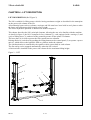
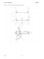
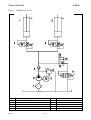
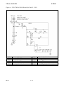
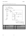
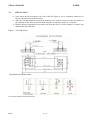
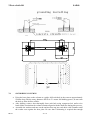
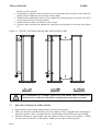
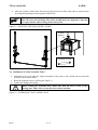
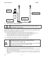
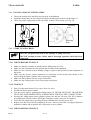
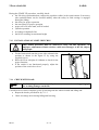
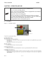
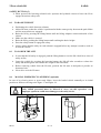
2 Post vehicle lift SAE40 USE AND MAINTENANCE MANUAL Original instruction ELECTRO-HYDRAULIC 2 POST LIFT SAE40 REV. 01 1 / 32 2 Post vehicle lift SAE40 PRINTING CHARACTERS AND SYMBOLS Throughout this manual, the following symbols and printing characters are used to facilitate reading: Indicates the operations which need proper care Indicates prohibition Indicates a possibility of danger for the operators BOLD TYPE Important information WARNING: before operating the lift and carrying out any adjustment, read carefully chapter 7 “installation” where all proper operations for a better functioning of the lift are shown. REV. 01 2 / 32 2 Post vehicle lift SAE40 CONTENTS 1 GENERAL INFORMATION 4 2 PRODUCT IDENTIFICATION 6 3 PACKING, TRANSPORT AND STORAGE 7 4 PRODUCT DESCRIPTION 8 5 TECHNICAL SPECIFICATION 9 6 SAFETY 17 7 INSTALLATION 19 8 OPERATION AND USE 26 9 MAINTENANCE 29 10 TROUBLESHOOTING 30 REV. 01 3 / 32 2 Post vehicle lift SAE40 CHAPTER 1 – GENERAL INFORMATION This chapter contains warning instructions to operate the lift properly and prevent injury to operators or objects. This manual has been written to be used by shop technicians in charge of the lift (operator) and routine maintenance technician (maintenance operator). The operating instructions are considered to be an integral part of the machine and must remain with it for its whole useful life. Read every section of this manual carefully before operating the lift and unpacking it since it gives helpful information about: - SAFETY OF PEOPLE - SAFETY OF THE LIFT - SAFETY OF LIFTED VEHICLES The company is not liable for possible problems, damage, accidents, etc. resulting from failure to follow the instructions contained in this manual. Only skilled technicians of AUTHORISED DEALERS or SERVICE CENTRES AUTHORISED by the manufacturer shall be allowed to carry out lifting, transport, assembling, installation, adjustment, calibration, settings, extraordinary maintenance, repairs, overhauling and dismantling of the lift. THE MANUFACTURER IS NOT RESPONSIBLE FOR POSSIBLE DAMAGE TO PEOPLE, VEHICLES OR OBJECTS IF SAID OPERATIONS ARE CARRIED OUT BY UNAUTHORIZED PERSONNEL OR THE LIFT IS IMPROPERLY USED. Any use of the machine made by operators who are not familiar with the instructions and procedures contained herein shall be forbidden. 1.1 MANUAL KEEPING For a proper use of this manual, the following is recommended: • Keep the manual near the lift, in an easily accessible place. • Keep the manual in an area protected from the damp. • Use this manual properly without damaging it. • Any use of the machine made by operators who are not familiar with the instructions and procedures contained herein shall be forbidden. This manual is an integral part of the lift: it shall be given to the new owner if and when the lift is resold. 1.2 OBLIGATION IN CASE OF MALFUNCTION In case of machine malfunction, follow the instructions contained in the following chapters. REV. 01 4 / 32 2 Post vehicle lift 1.3 SAE40 CAUTIONS FOR THE SAFETY OF THE OPERATOR Operators must not be under the influence of sedatives, drugs or alcohol when operating the machine. Before operating the lift, operators must be familiar with the position and function of all controls, as well as with the machine features shown in the chapter “Operation and use” 1.4 WARNINGS Unauthorized changes and/or modifications to the machine relieve the manufacturer of any liability for possible damages to objects or people. Do not remove or make inoperative the safety devices, this would cause a violation of safety at work laws and regulations. Any other use which differs from that provided for by the manufacturer of the machine is strictly forbidden. The use of non genuine parts may cause damage to people or objects DECLARATION OF WARRANTY AND LIMITATION OF LIABILITY The manufacturer has paid proper attention to the preparation of this manual. However, nothing contained herein modifies or alters, in any way, the terms and conditions of manufacturer agreement by which this lift was acquired, nor increase, in any way, manufacturer’s liability to the customer. TO THE READER Every effort has been made to ensure that the information contained in this manual is correct, complete and up-to date. The manufacturer is not liable for any mistakes made when drawing up this manual and reserves the right to make any changes due the development of the product, at any time. REV. 01 5 / 32 2 Post vehicle lift SAE40 CHAPTER 2 – PRODUCT IDENTIFICATION The identification data of the machine are shown in the serial plate placed on the power side column. Use the above data both to order spare parts and when getting in touch with the manufacturer (inquiry). The removal of this label is strictly forbidden. Machines may be updated or slightly modified from an aesthetic point of view and, as a consequence, they may present different features from these shown, this without prejudicing what has been described herein. 2.1 WARRANTY CERTIFICATE The warranty is valid for a period of 12 months starting from the date of the purchase invoice. The warranty will come immediately to an end when unauthorized modifications to the machine or parts of it are carried out. The presence of defects in workmanship must be verified by the Manufacturer’s personnel in charge. 2.2 TECHNICAL SERVICING For all servicing and maintenance operations not specified or shown in these instructions, contact your Dealer where the machine has been bought or the Manufacturer’s Commercial Department. REV. 01 6 / 32 2 Post vehicle lift SAE40 CHAPTER 3 - PACKING, TRANSPORT AND STORAGE Only skilled personnel who are familiar with the lift and this manual shall be allowed to carry out packing, lifting, handling, transport and unpacking operations. 3.1 PACKING The packing of the lift is delivered in following components: N. 1 base unit packed in a steel frame, wrapped up in non-scratch material, including the all accessories. N. 1 power unit packed in a carton box. N. 1 electric panel packed in a carton box (If requested, optional accessories are available to satisfy each customer’s requirements). Figure 1 - PACKAGES 3.2 LIFTING AND HANDLING When loading/unloading or transporting the equipment to the site, be sure to use suitable loading (e.g. cranes, trucks) and hoisting means. Be sure also to hoist and transport the components securely so that they cannot drop, taking into consideration the package’s size, weight and centre of gravity and it’s fragile parts. 3.3 STORAGE AND STACKING OF PACKAGES Packages must be stored in a covered place, out of direct sunlight and in low humidity, at a temperature between -10°C and +40°C. 3.4 DELIVERY AND CHECK OF PACKAGES When the lift is delivered, check for possible damages due to transport and storage; verify that what is specified in the manufacturer’s confirmation of order is included. In case of damage in transit, the customer must immediately inform the carrier of the problem. Packages must be opened paying attention not to cause damage to people (keep a safe distance when opening straps) and parts of the lift (be careful the objects do not drop from the package when opening). REV. 01 7 / 32 2 Post vehicle lift SAE40 CHAPTER 4 - LIFT DESCRIPTION LIFT DESCRIPTION (Ref. Figure 2) The lift is suitable for lifting motor vehicles having maximum weight as described in the nameplate on the power side column of the lift. All mechanical parts such as columns, carriages and lift arms have been built in steel plate to make the frame stiff and strong while keeping a low weight. The electro hydraulic operation is described in detail in chapter 8. This chapter describes the lift’s principal elements, allowing the user to be familiar with the machine. As shown in figure 2, the lift is composed of two columns (1), each equipped with a carriage (2) and a pair of lifting arms (3), anchored to the ground by means of base plates of columns. The base plate (4) is used to protect the lines routed between columns. Raising motion is carried out by pushing the lifting button on the control panel (5) to operate a power unit (6), which delivers the hydraulic fluid to cylinders inside the columns. The synchronization is controlled by the equalizer cable system built in each column. The arm safety can be engaged automatically when the lift is raised. A limit switch is installed on the power side column for the maximum lifting height. Figure 2 – LIFT 1 5 2 3 6 4 REV. 01 8 / 32 2 Post vehicle lift SAE40 CHAPTER 5 - TECHNICAL SPECIFICATION 5.1 SIZE AND MAIN FEATURES (Ref. Figure 3) CAPACITY Maximum lifting height Minimum lifting height Overall height Overall width Width between columns Maximum vehicle width Lifting time Lowering time Noise level Working temperature Average weight of package 5.2 4000kg 1900mm 85mm 2830mm 3160 mm 2820 mm 2580 mm 40 s 60 s 70 dB(A)/1m -10 °C ÷ 40 °C 620kg ELECTRIC MOTOR Type Voltage Power N° Poles Speed Motor enclosure type Insulation class ML90L2 G90N4 230V/220V-1Ph 2.2 KW 2 2800 rpm 400V/380V-3Ph 2.2 KW 4 1375 rpm B14 IP 54 Motor connection must be carried out referring to the attached wiring diagrams figure 6. The motor direction of rotation is shown in the label placed on the motor. Before use of the lift, make sure to check if the motor specification shown in the nameplate of the motor conforms to the local electric supply. If there is over 10% fluctuation on the electrical power supply, it is suggested to use the voltage stabilizer to protect the electrical components and system from overloading. 5.3 PUMP Type Flow rate Continuous working pressure Peak pressure REV. 01 Gear 3 4.8 cm3/g 2.0 cm /g 170 bar - 190 bar 210 bar 9 / 32 2 Post vehicle lift SAE40 Figure 3a – LAYOUT (Two post with electrical release) REV. 01 10 / 32 2 Post vehicle lift 5.4 SAE40 HYDRAULIC POWER UNIT The power unit is equipped with Figure 4 – HYDRAULIC POWER UNIT Emergency lowering screw Motor Lowering solenoid valve Maximum pressure valve Oil hole 5.5 Oil tank OIL Use wear proof oil for hydraulic drive, in conformity with ISO 6743/4 rules (HM class). The oil with features similar to those shown in the table is recommended. TEST STANDARDS FEATURES VALUE ASTM D 1298 ASTM D 445 ASTM D 445 ASTM D 2270 ASTM D 97 ASTM D 92 ASTM D 644 Density 20°C Viscosity 40°C Viscosity 100°C Viscosity index Pour point Flash point Neutralization number 0.8 kg/l 32 cSt 5.43 cSt 104 N° ∼ 30 °C 215 °C 0.5 mg KOH/g CHANGE HYDRAULIC OIL REV. 01 AT 1 YEAR INTERVALS 11 / 32 2 Post vehicle lift SAE40 Figure 5 - HYDRAULIC PLAN 1 2 3 4 5 6 REV. 01 Master hydraulic cylinder Slave hydraulic cylinder Stop valve 7 8 9 10 11 Non return valve Gear pump 12 / 32 Oil filter Maximum pressure valve Motor Solenoid lowering valve Lowering speed control 2 Post vehicle lift SAE40 Figure 6a – ELECTRICAL DIAGRAM (380V/400V - 3PH) QS M FR TC KM YV REV. 01 Power switch Motor 2.2KW 3PH Overhead protector Transformer 150VA AC Contactor Lowering solenoid valve MQ1-4 SB1 SB2 SB3 HL SQ1 13 / 32 Unlock solenoid valve Lifting pushbutton Lowering pushbutton Lock pushbutton Pilot lamp Max. lifting height limit switch 2 Post vehicle lift SAE40 Figure 6b – ELECTRICAL DIAGRAM (220V/230 -1PH) QS M FR TC KM YV REV. 01 Power switch Motor 2.2KW 1PH Overhead protector Transformer 150VA AC Contactor Lowering solenoid valve MQ1-4 SB1 SB2 SB3 HL SQ1 14 / 32 Unlock solenoid valve Lifting pushbutton Lowering pushbutton Safety engaging pushbutton Pilot lamp Max. lifting height limit switch 2 Post vehicle lift SAE40 CHAPTER 6 – SAFETY Read this chapter carefully and completely because it contains important information for the safety of the operator and the person in charge of maintenance. The lift has been designed and built for lifting vehicles and making them stand above level in a closed area. Any other use is forbidden. The manufacturer is not liable for possible damages to people, vehicles or objects resulting from an improper or unauthorized use of the lift. For operator and people safety, a square space for a safety area at least 1m free away from the lift must be vacated during lifting and lowering. The lift must be operated only from the operator’s control site in this safety area. Operator’s presence under the vehicle, during working, is only admitted when the vehicle is lifted and the safety lock is engaged. Never use the lift when safety devices are off-line. People, the lift and the vehicles lifted can be seriously damaged if these instructions are not followed. 6.1 GENERAL WARNINGS The operator and the person in charge of maintenance must follow accident-prevention laws and rules in force in the country where the lift is installed. They also must carry out the following: • Neither remove nor disconnect hydraulic, electric or other safety devices; • Carefully follow the safety indications applied on the machine and included in the manual; • Observe the safety area during lifting; • Be sure the motor of the vehicle is off, the gear engaged and the parking brake put on; • Be sure only authorized vehicles are lifted without exceeding the maximum lifting capacity; • Verify that no one is on the arms during lifting or standing. REV. 01 15 / 32 2 Post vehicle lift 6.2 SAE40 SAFETY DEVICE To avoid overloading and possible breaking, the following safety devices have been used: A maximum pressure valve placed inside the hydraulic unit to prevent excessive weight. The maximum pressure valve has been preset by the manufacturer to a proper pressure. DO NOT try to adjust it to overrun the rated lifting capacity. A safety valve (stop valve) built in each hydraulic cylinder to prevent the lift from sudden lowering in case of hydraulic pipe line broken or failure. A special designed the safety mechanism with automatic engagement, built in each carriage for lifting safety. It is strictly forbidden to modify any safety device. Always ensure the safety device for proper operation during the service. 6.3 SAFETY SINGS All safety warning signs (ref. figure 8) displayed on the machine are with the purpose to draw the operator’s attention to dangerous or unsafe situations. The labels must be kept clean and they have to be replaced if detached or damaged. Read the meaning of the labels carefully and memorize it. Figure 8 – SAFETY SIGNS REV. 01 16 / 32 2 Post vehicle lift REV. 01 SAE40 17 / 32 2 Post vehicle lift SAE40 CHAPTER 7 – INSTALLATION Only skilled technicians, appointed by the manufacturer, or by authorized dealers, must be allowed to carry out installation. Serious damage to people and to the lift can be caused if installations are made by unskilled personnel. Always refer to the exploded views attached during installation. 7.1 TOOL REQUIRED ✟ ✟ ✟ ✟ ✟ ✟ 7.2 ✟ ✟ ✟ ✟ ✟ ✟ Rotary Hammer Drill D.18 Masonry Bit Hammer Level Open-End Wrench Set Medium Crescent Wrench Hex-Key/Allen Wrench Set Crow Bar For Shim Installation Chalk Line Medium Cross Screwdriver Medium Flat Screw river Tape Measure CHECKING FOR ROOM SUITABILITY The lift has been designed to be used in covered and sheltered places free of overhead obstructions. The place of installation must not be next to washing areas, painting workbenches, solvent or varnish deposits. The installation near to rooms, where a dangerous situation of explosion can occur, is strictly forbidden. The relevant standards of the local Health and Safety at Work regulations, for instance, with respect to minimum distance to wall or other equipment, escapes and the like, must be observed. 7.3 LIGHTING Lighting must be carried out according to the effective regulations of the place of installation. All areas next to the lift must be well and uniformly lit. 7.4 FLOOR REQUIREMENT The machine should be fixed on dry ground with less than 5mm level error without dust or other pollution. The earth of the concrete should be thicker than 200mm and the strength should be 3000PSI (2.1Kg/MM2). The basic size of the ground should be of 4000MM length, 1000MM width, 350MM depth. It is suggested to fix concrete iron to improve the fastness of the ground. (See the ground fixing table). Notice to choose proper ground fixing table according to the machine chosen. Specifications of concrete must be adhered to. Failure to do so could cause lift failure resulting in personal injury or death. A level floor is suggested for proper installation. Small differences in floor slope may be compensated for by proper shimming. Any major slope change will affect the level lifting performance. If a floor is of questionable slope considering to pour the new concrete slab. REV. 01 18 / 32 2 Post vehicle lift 7.5 SAE40 SITE LAYOUT • • • Now locate the lift according to the floor plan the figure 9, use a carpenters chalk line to layout a grid for the column locations After the column locations are properly marked, use a chalk or crayon to make an outline of the columns on the floor at each location using the column base plates as a template. Double check all dimensions and make sure that the bases of each column are square and aligned with the chalk line Figure 9 – FLOOR PLAN Expansible bolt fixation chart Two post lift with electrical release(4.0T) REV. 01 19 / 32 2 Post vehicle lift 7.6 SAE40 ANCHORING COLUMNS • Using the base plate on the column as a guide, drill each hole in the concrete approximately 150mm deep with the rotary hammer drill D.18. To assure full holding power, do not ream the hole or allow drill to wobble; • After drilling, remove dust thoroughly from each hole using compressed air and/or wire brush. Make certain that the column remains aligned with the chalk line during this process; • Assemble the washers and nuts on the anchors then tap into each hole with a hammer until the washer rests against the base plate. Be sure that if shimming is required that enough REV. 01 20 / 32 2 Post vehicle lift • • • • SAE40 threads are left exposed; If shimming is required, insert the shims as necessary under the base plate so that when the anchor bolts are tightened, the columns will be plumb; With the shims and anchor bolts in place, tighten by securing the nut to the base. DO NOT use an impact wrench for this procedure; Anchor another column as outlined in above steps; Check to make sure that the columns for square-ness and plumb are as shown in the figure 10. Figure 10 – CHECK COLUMNS FOR SQUARE-NESS AND PLUMB The requirements for column’s square-ness and plumb must be adhered to. Failure to do so could cause lift failure resulting in personal injury or death. 7.7 ROUTING THE EQUALIZER CALBES • • • REV. 01 Raise and lock each carriage approximately 1m above the ground; Make sure that the mechanical safety on each column are fully engaged before attempting to route the equalizer cables. Carriages must be equal height from the floor before proceeding; With the carriages in equal height, route the equalizer cables as shown in the figure 11. Make sure the cables in the place on the pulleys. Make sure the cables routed properly; 21 / 32 2 Post vehicle lift SAE40 After the equalizer cables have been routed, adjust the nut to make each cable in equal tension by using the adjusting wrench supplied with the lift. • The equalizer cables should be checked weekly for equal tension. Failure to do this will cause uneven lifting. The cables should always be adjusted so that they are equal tension when resting on the safety locks. Figure 11 – ROUTING THE EQUALIZER CALBES Adjusti ng nuts Adjsuting wrench 7.8 HYDRAULIC LINE CONNECTION • • • Attach the power unit onto the support mounted on the power side column and secured with included screws and washers. Route the hydraulic hoses referring the figure 12. Tighten the fittings thoroughly. When routing the hydraulic hose, make sure that the hose is clear of any moving part. Make sure to keep the hoses clean from dust. Figure 12 – HYDRAULIC LINE CONNECTION REV. 01 22 / 32 2 Post vehicle lift SAE40 Hydraulic power unit Hydraulic cylinder Hydraulic hose L=2830mm Hydraulic hose L=1800mm 7.9 PNEUMATIC SYSTEM CONNECTION When routing the pneumatic line, make sure that the pneumatic line is clear of any moving part. Failure to do so may result in safety lock failure which may result in damage or personal harm. The pneumatic supply at site (to which the pneumatic system of the lift is connected) must be equipped with a servicing unit composed of water separator, lubricator and pressure reducer. These devices can be supplied by the manufacturer on request. For the connection of the pneumatic lines proceed as follow referring to the figure 7: • Fix the supplied solenoid air valve onto the power-side column using the included screws; • Connect the pneumatic lines pre-assembled in the lift to the solenoid air valve; • Connect the pneumatic system of the lift to the pneumatic supply at site; • Check the pneumatic control operations for proper performance. 7.10 MAKE THE ELECTRICAL HOOKUP TO POWER UNIT The hookup work must be carried out by a qualified electrician. Make sure that the power supply is right. Make sure the connection of the phases is right. Improper electrical hook-up can damage motor and will not be covered under warranty. The power unit must be kept dry. • • • REV. 01 Fix the control panel onto the power-side column using the included screws. Make the electric hookup to the hydraulic power unit referring to the attached wiring diagram (figure 5) using the included cables; Make sure the connection of the phases is right and the lift is grounded (if no special request, normally, black wires are for phase lines, the blue is for “0” line and the yellow/green is for grounding). 23 / 32 2 Post vehicle lift 7.11 • • • SAE40 INSTALLATION OF LIFTING ARMS Grease the carriage tube and all pivot pins prior to installation. Install the lifting arms on the carriages using the included pins as shown in the figure 13. Check for proper engagement of the arm safety. Adjust it if necessary (ref. Fig. 14) Fig. Fig.12 13 Fig. 14 Adjusting bolt Adjusting bolts 7.12 START-UP AND CHECK DO NOT run power unit with no oil. Damage to pump can occur. DO NOT attempt to raise vehicle until a thorough operation check has been completed. 7.12.1 CHECK BEFORE START-UP • • • • • • Make sure that the columns are plumb and the lifting arms are level. Make sure the lift anchored to the ground and all anchor bolts tightened. Make sure the electrical system feeding voltage is equal to that specified in the nameplate on the motor. Make sure the electric system connection in conformity of the electric plan shown as the electric diagram figure 6 and the lift for proper grounding. Make sure the hydraulic line for proper connection. Make sure the working area is free from people and objects. 7.12.2 START-UP • • • • • • Pour oil in the tank (about 10 liters more then one time). Feed the lift by the power switch. Test the power unit by pushing the lifting button. IF MOTOR GETS HOT OR SOUNDS PECULIAR, STOP IMMEDIATELY AND RECHECK THE ELECTRIC CONNECTIONS Pressing the lifting button until cylinders bottom out and the lift stops. DO NOT continue pressing button after lift reaches full height. Damage to motor can occur if continued. Lower the lift completely by pressing the power handle placed on the power unit. Repeat raise and lower the lift completely at least 3 times to bleed the air trapped inside the hydraulic cylinder and to equalize the oil pressure in each cylinder. 7.12.3 CHECK DURING START-UP REV. 01 24 / 32 2 Post vehicle lift SAE40 During the START-UP procedure, carefully check: • the lift rising synchronization, readjust the equalizer cables in the equal tension if necessary (the synchronization can be checked audibly when the safety in each carriage is engaged during the lifting) • the safety for proper operation • the arm safety for proper operation • proper oil level in the tank, refill if needed • cylinder operation • no leakage in hydraulic line • the lift for reaching its maximum height 7.13 INSTALLATION OF LIMIT SWITCHES Only skilled personnel must be allowed to carry out this operation. An improper adjustment of limit switches could cause damages to the lift, objects and people. • • • 7.14 Fix the limit switch onto the power-side column in the position as shown in the figure 15 by using the supplied screws. Raise the lift at a height of 1800mm to check for the proper function; If the switch is not functioned properly, adjust the position of the switch lever lever. Fig. 15 CHECK WITH LOAD WARNING: please follow carefully the instructions in the coming paragraph for avoiding damages on the lift. Carried out two or three complete cycles of lowering with the vehicle loaded and lifting and: • Repeat the checks provided for by 7.11.3. • Check no strange noise during lifting and lowering REV. 01 25 / 32 2 Post vehicle lift SAE40 CHAPTER 8 - OPERATION AND USE Never operate the lift with any person or equipment below. Never exceed the rate lifting capacity. Always ensure that the mechanical safeties are engaged before any attempt is made to work on or near the vehicle. Always lift a vehicle on the lifting pads. Never leave the lift in an elevated position unless the safeties are engaged. If an anchor bolt becomes loose or any component of the lift is found to be defective, DO NOT USE THE LIFT until repairs are made. Do not permit the electric control panel to get wet! 8.1 CONTROLS Figure 16 - CONTROL PANEL 1 2 3 5 4 Controls for operating the lift are: POWER SWITCH (1) The switch can be set in two positions: 0 position: the lift electric circuit is not powered; the switch can be padlocked to prevent the use of the lift. 1 position: lift electric circuit is powered PLIOT LAMP (2) It shows that the electric circuit is powered LIFTING BUTTON (3) When pressed, the motor and hydraulic circuit are operated and the lift will be raised LOWERING BUTTON (4) When pressed, the lift will take seconds to release the safety by means of the electromagnets and then the lowering solenoid valve is powered: the lift begins to lower under its weight and the load lifted. REV. 01 26 / 32 2 Post vehicle lift SAE40 SAFETY BUTTON (5) When pressed, the lowering solenoid valve operates the hydraulic circuit to lower the lift to engage the nearest safety rack. 8.2 TO RAISE THE LIFT • • • • • • • 8.3 Positioning the vehicle between columns. Adjust lift arms so that the vehicle is positioned with the centre gravity between the pads. Make sure the arm safeties are engaged. Raise the lift by pressing the lifting button until the lifting adaptors contact underside of the vehicle. Make sure the vehicle is secured. Raise the lift by pushing the lifting button until reaching the desire height. Press the safety button to engage the safety. Always ensure that the safety in each column is engaged before any attempt is made to work on or near the vehicle. TO LOWER THE LIFT • • • • 8.4 In case that the lift safety is engaged, push the lifting button to rise the lift a little bit to clear of safety at first; Lower the vehicle by pressing the lowering button: the lift will take seconds to release the safety and then begin to lower under the weight of the load lifted; Before removing vehicle from the lift area, position the lift arms to and pads to provide an obstructed exit; Never drive over the lift arms. MANUAL EMERGENCY LOWERING (optional) In case of no electric power or power unit failure, lower the loaded vehicle manually to its initial position as follows referring to the figure 17 and figure 18: Only skilled personnel must be allowed to carry out this operation. An improper operation could cause damages to the safety device. Fig. 17 Fig. 18 1 1 2 REV. 01 27 / 32 2 Post vehicle lift • • • • • SAE40 Padlock the power switch; If the safety is engaged, operate the emergency hand pump (fig. 17 – 1, if any) to raise the lift a little bit to clear off the mechanical safeties. Keep pressing the emergency button on the solenoid air valve (fig. 18 – 1); To lower the lift, unloosen the emergency screw (fig. 17 – 2) of the lower solenoid valve by turning it anticlockwise. Screwing or unloosing the screw can reduce or increase the lowering speed; Retighten the emergency screw (fig. 17 - 2) by turning it clockwise. After manual lowering of the lift, reset ordinary operating conditions. Lift cannot be lifted if lowering valve is opened. REV. 01 28 / 32 2 Post vehicle lift SAE40 CHAPTER 9 – MAINTENANCE Only trained personnel who knows how the lift works, must be allowed to service the lift. To service properly the lift, the following has to be carried out: • use only genuine spare parts as well as equipment suitable for the work required; • follow the scheduled maintenance and check periods shown in the manual; • discover the reason for possible failures such as too much noise, overheating, oil blow-by, etc. • refer to documents supplied by the manufacture or dealer to carry out maintenance. Before carrying out any maintenance or repair on the lift, disconnect the power supply, padlock the general switch and keep the key in a safe place to prevent unauthorized persons from switching on or operating the lift 9.1 ORDINARY MAINTENANCE The lift has to be properly cleaned at least once a month using self-cleaning clothes. The use of water or inflammable liquid is strictly forbidden Be sure the rod of the hydraulic cylinders is always clean and not damaged since this may result in leakage from seals and, as a consequence, in possible malfunctions. 9.2 PERIODIC MAINTENANCE Daily preoperation Every 1 month • • • • • • • • • • • • • • • • Every 12 months • REV. 01 Check hydraulic connections and hoses for leaks Check safety lock audibly and visually while in operation Check arm locks Check bolts, nuts and screws are tight Check all chain/cable connections, pins and bolts to insure proper mounting Inspect all anchor bolts and retighten if necessary Check columns for square-ness and plumb Check equalizer cable tension, adjust if necessary Check all arm pivot pins. Make sure they are properly secured Check all lifting pads, replace if necessary Lubricant columns with grease Check the hydraulic oil, fill or replace if necessary Check hydraulic systems for proper operation Verify that all components and mechanisms are not damaged Verify the equalizer cables are not worn up to 5%, change if necessary Check the electrical system to verify that the motor, limit switch and control panel operate properly (this work must be carried out by skilled electricians) empty the oil tank and change the hydraulic oil 29 / 32 2 Post vehicle lift SAE40 CHAPTER 10 - TROUBLESHOOTING A list of possible troubles and solutions is given below: TROUBLE: POSSIBLE CAUSE: SOLUTION: The main switch is not turned on Turn the switch on Check Power on to restore if necessary Reconnect Check for correct voltage Replace Check the vehicle weight Interchange the two phases on the main switch There is no power The lift does not work The electrical wires are disconnected Fuses are blown The lift is overloaded The motor direction of rotation is not correct. The oil in the power unit is not sufficient. The lift does not raise The UP button is faulty. The maximum pressure valve clogged or leaks The lowering valve does not close. The suction tube or pump filter is dirty. Presence of air in the hydraulic system The lifting capacity is not sufficient The lift does not lower when the lowering button is pressed The lift does not lower smoothly The motor does not stop when the lift reaches it maximum height The pump is faulty Oil leakages in hydraulic circuit The lowering valve does not work properly The electric-magnetic piston for safety lock is faulty The equalizer cables are not in the same tension. Presence of air in the hydraulic system Lubrication of sliders is not enough. Sliders are damaged The maximum height limit switch does not work If the problems remain unsolved, call for technical support. REV. 01 30 / 32 Add some hydraulic oil Check UP button and connection for proper operation. Replace if needed Check and clean if dirty or replace if faulty Check and clean, if dirty or replace if faulty Check and clean if needed. Bleed the hydraulic system Check the pump and replace if needed. Check the circuit for any leakage Check the valve and replace if needed. Check, replace if faulty Readjust the equalizer cables. Bleed the hydraulic system Grease Replace Check the limit switch and replace if needed 2 Post vehicle lift REV. 01 SAE40 31 / 32 2 Post vehicle lift SAE40 Taicang Chengming Hydraulics Co., Ltd. Add: No. 90 North chengxi Rd, Chengxiang Town, Taicang City, Jiangsu Province, P. R. China Tel: (86)-0512-53404638 Fax: (86)-0512-53409828 E-mail: [email protected] Http: hydraulic.en.alibaba.com REV. 01 32 / 32