1
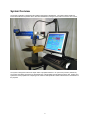
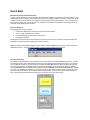
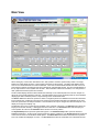
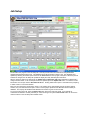
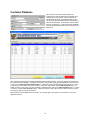
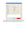
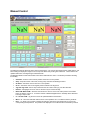
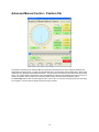
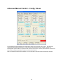
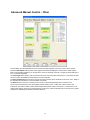
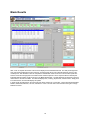
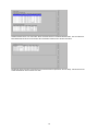
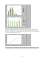
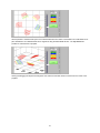
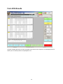
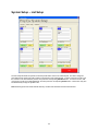
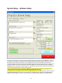
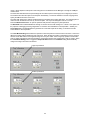
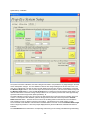
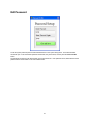
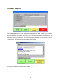
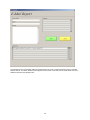
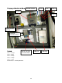
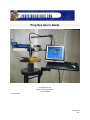
Prop-Eye User’s Guide Propstraightener.com 2080 Paul Edmondson Drive Iuka, MS 38852 1-662-423-9588 2010-08-16 KLP Table of Contents System Overview ...........................................................................................................................................................3 Quick Start .....................................................................................................................................................................4 Main View ......................................................................................................................................................................6 Job Setup .......................................................................................................................................................................8 Customer Database ..................................................................................................................................................... 10 Manual Control ............................................................................................................................................................. 13 Advanced Manual Control – Position Tab .................................................................................................................... 15 Advanced Manual Control – Config. Values................................................................................................................. 16 Advanced Manual Control – Other ............................................................................................................................... 17 Blade Results ............................................................................................................................................................... 18 Form 2034 Results ....................................................................................................................................................... 22 System Setup – List Setup ........................................................................................................................................... 23 System Setup – Software Setup .................................................................................................................................. 24 System Setup – Calibration .......................................................................................................................................... 26 Edit Password .............................................................................................................................................................. 27 Customer Reports ........................................................................................................................................................ 28 INI File.......................................................................................................................................................................... 30 Propeye Electrical Box - Fuses .................................................................................................................................... 32 2 System Overview The Prop-Eye software is developed using National Instruments LabVIEW 8.6. The system utilizes a National Instruments USB data acquisition device, Animatics SmartMotors, CMI gear head, and touch screen all-in-one PC. The system is designed to assess the repair status of propellers between 7.25” (184.15mm) and 63” (1600.2mm). The system does this by performing an automated scan of the propeller and calculating the pitch, rake, tracking and squareness of the propeller then comparing those results to ISO specification 484/2 to determine the classification of the propeller. 3 Quick Start Mount the Scanning Arm to the Propeller In order to begin scanning a prop, the scanning arm must first be installed on a propeller in the proper location. The distance from the laser sensor to the propeller must be within the working envelope of the laser. The laser for the 60” (1524mm) Propeye has an offset of 7.87” (200mm) and a working range of 19.68” (500mm). This means the top of the propeller to be scanned must be at least 7.87” (200mm) from the laser and the bottom of the prop must be no more than 19.68” (500mm) from the laser. Power-on Sequence When setting up the Propeye system: 1. Connect the cable from the scanning arm to the electronics cabinet. 2. Turn on power to the electronics cabinet. 3. Connect USB cable from electronics cabinet to PC. 4. Run Propeye software. Powering down the system should be performed in the reverse order; however, the cable connection between the scanning arm and the electronics cabinet may remain connected. Note: If a popup window appears displaying “Error -200478," click the Stop button. Disconnect and reconnect the USB cable to the PC. Then click the arrow at the top of the Propeye window as shown below. Set Laser Floor Value After setting up all parameters on the Job Setup tab for a scan, the floor must be established for the scan. The floor is the limit the system uses to distinguish the lower edge of the blade from objects below the blade. To set the floor, go to the Manual Control tab, turn on the laser by pressing the Laser On button and then positioning the scanning arm in a position between the blades where it is measuring the distance to the highest object below the propeller. Press the Set Floor button to establish the floor distance or select Manual click inside the Laser Floor box and type in a value. The software then subtracts a .25” (6.35mm) from the floor distance and assumes the lowest part of the blade to be scanned is at least .25” (6.35mm) above the floor reading. So, if the floor is at 20” (508mm) from the laser, it assumes the lowest part of the propeller is no more than 19.75” (501.65mm) away. 4 Start a Scan After all setup is complete, press either the Quick Scan or Full Scan button to begin scanning. The system then prompts the operator to position the scanner adjacent to the first blade to be scanned. After clicking the Continue button on the pop up panel, the Propeye begins an automatic scan. After each scan is completed the data will be updated on the Blade Results tab as the machine returns to the start position. When performing a scan, job setup information does not have to be saved. The software uses the information currently displayed on the Job Setup tab. If a change is made, but not saved, the new information will be used, until the saved information is recalled by reselecting the job from the Active Job list. Viewing results After each radius scan completes, the data in the Blade Results tab updates, and the user can view these results. After all radii have been scanned, the raw data file is stored in the results file whose location is specified in System Setup. Scan reports may be generated and printed or emailed by pressing the Reports button. 5 Main View When viewing any of the 3 tabs, items like the time, date, position, and active job are always visible. The Angle, Radius, and Laser display show the current position information for the Propeye. The Status LED displays green when no error is detected and red if a fault is detected. The Laser On LED indicates whether the laser is on or off. This status is important as looking into the laser is dangerous and potentially harmful. The time and date display at the top right show the current system time and date. This information is taken from Windows, so to change time or date, update the Windows system time and date. The blue radius display above the tabs indicates the radii setup on the Job Setup tab to be scanned. Grayed out values are not currently selected for scanning. The radio buttons at the end of the display allow the choice between displaying the radii in absolute position or as percentage of the overall blade radius. The Active Job list box allows the operator to select a configured job from the database and shows the information for the selected job. Certain items such as the ID, Customer and propeller information are duplicated on the right side of the panel under Job Setup Parameters. This information can only be changed from the Job Setup tab. The display on the right is for display only. The Rotation Servo motor controls are also available on the right side of the panel. The Release button allows the Propeye to be moved manually. It disengages the servo motor drive. The Set Home button sets the Propeye’s current position as home and the Go Home button sends it to the home position. The System Setup button opens the System Setup panel. The Customer Setup button opens the Customer Database Setup panel. Access to both of these panels may require a password. The Print Screen button sends the current view on screen to the Windows default printer. The Recall Scan button allows saved data from a previous scan to be recalled and displayed on screen. The Full Scan button starts an automated scan of all blades and the 6 Quick Scan button starts an automated scan of only 1 blade. The Exit button stops the program and exits. To save, email or print customer reports, press the blue Reports button on the left of the panel. Between the Reports button and the Exit button is the status information display. General system status information and errors are displayed here. 7 Job Setup The first tab in the program is the Job Setup tab. This tab provides a front end interface for the job database (implemented with Microsoft Access). This database stores all information to define a job. The displayed job is updated by selecting the desired job to view from the Active Job list in the top right of the panel. When the pick list selection is changed, the Job Setup tab updates to display the newly selected job’s information. When a change is made to an existing job, the Update Job and Save New Job buttons will blink to indicate that a change has been made. If the current job needs to be updated, press the Update Job button. To save the current information as a new job, click the Save New Job Button. Clicking either button opens a confirmation box prompting to either confirm or cancel the selection. Each new job is assigned a unique Shop Job ID. This number can be changed after the job has been created; however, any new value must be unique in order to ensure proper operation of the Microsoft Access-based job database. The Propeye ID identifies what hardware was used for a given set of scan data. To remove a job from the list, press the Delete Job button at the lower left of the panel. A box will ask for confirmation to delete the currently selected job. When entering a new job the Clear Fields button can be used to reset the values on the Job Setup tab to default values. 8 The Job database is linked to the program by selecting the corresponding UDL file in the system setup panel. Double clicking on the Job_1.UDL file in Windows Explorer opens the Data Link Properties window. From this window the location of the Job_1.mdb file is specified. The MDB file is the Access Database file that stores all of the data. The database and UDL file can be located on the local machine or on a network location. Refer to Microsoft Access documentation and help for more information on UDL and MDB files. The customer database can also be edited directly through Microsoft Access. The location of the UDL file is specified in the program by using the browse by on the setup panel to browse to the location of the UDL file. 9 Customer Database After customers are setup in the database, the Customer list on the Job Setup tab is populated with a complete list of all customers. When a customer is selected from the list the corresponding fields on the Job Setup tab will be populated with the corresponding data from the database. No information may be edited from the Job Setup tab. To edit the customer database press the Customer Setup button at the lower left of the main panel. After entering the password, the Customer Database interface panel will open. This panel displays all information in the Customer Access database. Information in the table can be sorted by selecting the desired sort column from the 6 choices in the Order Customer Database By box. Information cannot be edited directly from this panel. In order to edit customer information, click on the row of the customer to edit and then click the Edit Customer button. To delete a customer, click on the row of the customer to delete and then click on the Delete Customer button. To enter a customer, press the New Customer button. Clicking on either the Edit or New Customer button will open a panel for entering or editing customer information. When finished, click the Close button or click the “X” at the top right of the window to exit and return to the main application window. 10 The Enter New Customer panel allows the user to edit existing customer information or enter information for a new customer. All information on the panel may be edited except the time and date in the top right that store the time and date of the original customer entry. When complete press the Update Customer button to update or add the new information to the database. When finished, press the Exit button or click the “X” to close the window. 11 Double clicking on the Customer_1.UDL file in Windows Explorer opens the Data Link Properties window. From this window the location of the Customer_1.mdb file is specified. The MDB file is the Access file that stores all of the data. The database and UDL file can be located on the local machine or on a network location. Refer to Microsoft Access documentation and help for more information on UDL and MDB files. The customer database can also be edited directly through Microsoft Access. The location of the UDL file is specified in the program by using the browse by on the setup panel to browse to the location of the UDL file. 12 Manual Control The Manual Control tab allows for direct control of the Propeye. The current angle measurement, radial position, and laser reading are displayed in large font on the top of the tab for easy viewing from a distance. These numbers are updated at all times, including during an automated scan. The Rotation Master Control buttons allow control of the rotational servo motor. The buttons provide the following functionality: Set Home – Sets the motors current position as the zero or home position. Stop – Stops the motion of the motor, issuing a stop command not braking the motor. Go Home – Sends the motor to the home or zero position. Go To – Sends the motor to the angular position entered in the Angle box. Jog CW / Jog CCW – Send a step command to the servo motor and to jog it in either direction. Release – Disengages the servo motor so the axis may be moved manually. Blade CW / Blade CCW – Send the command for the servo to move to the same position on the blade before or after the one it is on. It uses the number of blades designated in the Job Setup tab to determine how large a step to take. 9° / 18° CW / CCW – Jog the servo motor the specified distance and direction. Mem 1 – 5 – Store the radial and rotation servos current positions into 1 of 5 different memory locations. Rec 1 – 5 – Send a go to position command to both servo motors and commands them to move to the corresponding stored positions. The positions are displayed in the 5 indicators above the Memory buttons. 13 The Radius Master control buttons provide the following functionality: Stop – Stops the motion of the linear slide Go Home – Sends the linear slide to the home position. Home is defined as 10” from the center. Go To – Sends the linear slide to the position in inches listed in the Radius control box Jog In / Out - Jogs the linear slide in and out. Radii – Sends the linear slide to the corresponding position based on the radius selected. The actual distance is determined based on the propeller setup from the Job Setup tab. Laser Control Laser On / Laser Off – Turns on or off the laser detector. Always turn the laser OFF if there is any chance of someone looking into the laser. Set Floor – Takes the current laser reading and sets it as the absolute floor for all measurements Laser Floor – Distance used as the floor for all measurements. Nothing greater than 95% of the floor value will be measured. The lowest part of all blades must be above this number. Manual / Auto – Determines if the floor is set automatically before beginning a scan or the number entered as Laser Floor is used. If set to automatic, the laser takes a reading before beginning the blade scan, and used 95% of that number as the floor value. Calculator Pitch / Rake Calc – determines if a pitch or rake calculation is to be performed between the 2 positions stored. Clear – Erases all stored locations Mem P1 / P2 - Stores the current laser height reading and angular or radial position into one of the 2 memory locations Calc Pitch / Rake – Performs the selected pitch or rake calculations on the data stored in the 2 memory locations and displays the result of the calculation Advanced Clear Status – Clears any errors stored in the servo motors. These include possible encoder or position errors caused by motor stall or an obstruction to the movement. Advanced Control – Opens the Advanced Manual control panel. 14 Advanced Manual Control – Position Tab The Position Control tab of the Advanced Manual Control panel provides direct access to adjust the rotational and radial positions of the Propeye. The dial controls rotational motion, and the slider controls radial motion. Most control options here are duplicates of the Manual Control tab. The jog buttons, home buttons, and release buttons are all the same. The numeric displays at the bottom of the panel display the scaled and raw readings for the laser input; servo position and position error; and the current encoder position read by the external data acquisition system. The Clear Flags buttons clear the status registers in the servo motors. If the motor has a position error, it sets a flag in the register. The motor will not operate until the error flag is cleared. 15 Advanced Manual Control – Config. Values The Configuration Values tab displays the configuration values used to setup the servo motors. This panel was created for system debug and checkout. Under normal use this panel should not be needed. However if a knowledgeable operator wishes to experiment with new PID control values or velocity and acceleration values for the servo motors, this panel allows those numbers to be entered and tested. Refer to Animatics Smartmotor documentation for more information on the PID values and what they represent. 16 Advanced Manual Control – Other The final tab on the Advanced Manual Control is where the status registers of the servo motors can be queried. Press the Read Status buttons and the 16 bit register of Booleans will display the contents of the status register. Refer to the Animatics register key on the right of the screen for meaning of each bit. A bright green light indicates a true, or set status register bit. The Clear Flags button sends a clear command to the servo motor and should reset all errors. If this does not reset all errors, refer to the Animatics documentation for more information. The Send Command buttons sends any text from the text box directly above the button to the servo motor. Refer to the Animatics documentation for a list of available commands. The Reset buttons can be use to reset the servo motors in case clearing the flags does not clear an error. The error boxes at the bottom of the panel display internal system errors. A VISA error is most common and indicates an error with the serial communication between the software and the servo motor. If a VISA error occurs, double check that the motors are connected properly, powered on, and the COM ports are set correctly in the system setup panel. Restarting the software should clear this error. 17 Blade Results After a scan is complete the results of the scan are displayed on the Blade Results tab. The radii percentages that were scanned are displayed at the top of the tab. Changing these values on this tab will update the values on the Job Setup tab. After all radius scans are complete the overall blade results are shown in the Overall Propeller box. This box shows the average pitch for the blade and the class that pitch is in when compared with the desired pitch. Individual blade and radius results are shown in the Blade Results table. The data displayed is selected by using the radio buttons to the left of the table. The table will display Pitch, Tracking, Squareness, or Rake results. Simply click in the desired item, and the table display will update. In depth results are displayed on the lower half of the tab in another set of 5 sub-tabs. These tabs are titled Detailed Results, ISO Results, Bar Plot, Line Plot, and 3D Plot. Press or mouse click on the text tabs to the right to change between the views. 18 Detailed Results shows more information about the blade selected in the Blade Results table. The Local Pitch For Each Blade Radii shows more information about the Radius selected in the Section Pitch table. ISO Results shows the pitch requirements for the Desired Class as specified in the Job Setup. Also shown are the actual classifications for the current scan data. 19 Bar Plot shows a graphical representation for the calculated pitch values. If All Blades is selected in the Select Blades list box, the displayed pitches are the mean pitches of each radius of each blade. If an individual blade is selected in the Select Blade list box, the displayed pitches are the Local pitches of each radius. The Select Class list box controls the horizontal classification limit lines. Line Plot shows a graphical representation of the all data points collected for the selected blade and radius. Vertical lines indicate the division of the data into locals. Leading and Trailing cursors indicate the boundaries of the data used for pitch calculations. The remaining cursors indicate the overall pitch and length as well as that of the locals. 20 3D Plot provides a 3 Dimensional layout of the collected data with each radius of each blade color coded based on its pitch classification. An individual blade can be singled out using the Select Blade list box. The Top View button provides an overhead view of propeller. Clicking and dragging the 3D plot will change the view, and the Zoom slider zooms in and out from the center of the propeller. 21 Form 2034 Results Along with the Blade Results tab, this tab is populated as the radii scans are completed. The data displayed here is based upon Form #2034 provided to Propstraightener.com. 22 System Setup – List Setup The List Setup tab allows the operator to edit the pick list items used on the Job Setup tab. The items configured here determine the values and order of items in the pick lists of the Job Setup tab. To add a new item to the list, type the new item in the box below the pick list, then press the corresponding Add New button. To remove an item, click on the item in the list so it is highlighted blue, and then press the corresponding Delete button. These items may also be edited directly through the system ini file. Note: Removing items from these lists will affect any recalled scan data that used the removed items. 23 System Setup – Software Setup The Customer UDL file and Job UDL file are the database link files for the customer and job databases. These may be located on the local drive or a network location. Press the file browse button at the end of the file box to open a file browse box and select the correct files. See the database sections for more information on the UDL files. The Results folder is the location where scan results will be logged in ASCII comma delimited format. This box does not expect a specific file. When the browse box is opened navigate to the desired folder and press the Current Folder button at the lower right of the file browse box. This button will select the current folder and not a specific file. This location also may be local or a remote network location. The Logo File location is the logo banner that is displayed at the top left of the main panel and displayed on the customer reports. This needs to be a PNG format file with the dimensions 95 X 765. The Slide Servo Port and Rotation Servo Port are the COM ports that are connected to the servo motors. These are USB to RS232 adapters in the control box of the Propeye. If the USB cable in unplugged or moved Windows will sometimes change COM port numbers. This will result in the software not being able to communicate with the 24 motors. Either adjust the COM ports on this setup panel or use Windows Device Manager to change the COM port numbers back. The Automated and Manual Scan speed settings set the rotation speed of the Propeye arm in degrees per second. The software also offers the option to email reports automatically. To allow the software to send an outgoing email, specify the SMTP mail server to be used. The Filter width setting is the width of the Median filter that is applied to the analog laser data. This averaging filter is used to smooth the data and remove any erroneous spikes. It is only a smoothing filter and not a curve fit. Press the Edit Password button to open the password edit panel and change the system password. The Raw Data button enables/disables the storage of raw laser and encoder readings to a *.dat file. This option is for the purposes of debugging scanning irregularities. It should be set to Disabled for normal operation. Similarly, the Locals Sheet button enables/disables the generation of a local data report file for debug. It should be set to No Locals Sheet for normal operation. The Laser Mount Setting button allows the operator to select the position in which the laser is mounted. There are 2 different mounting positions Small Prop and Large Prop. When Small Prop position is selected the Laser is mounted with the screws that hold the Laser together facing out so they are visible. When Large Prop position is selected the Laser is rotated 180 degrees and mounted with the screws that hold the Laser together facing away or hidden. When the Laser Mount Setting button is toggled the Prop Information limits for the Diameter setting will automatically change according to what mount is selected. Large Prop Selected Small Prop Selected 25 System Setup – Calibration The system has 2 basic calibrations, the laser scaling and the offset to compensate for any height change in the laser as the radial position changes. The first calibration scales the raw voltage readings from the laser into inches. The easy way to calibrate this is to place an object a known distance from the laser, enter the actual distance, and press the Measure Height 1 button. Then move the object to another known position, enter the second distance and press the Measure Height 2 button. Press the Calc. Scaling button to compute the scale and offset for those values. The offset should be close to the laser working envelope minimum of 7.87” (200mm) and the scale should approximately equal the measurement range 19.68” (500mm) divided by 10. The radial calibration corrects for any dip or drop in the laser position as it moves from the home position to the end of travel. To best perform this calibration, place the Propeye above a flat level surface and press the Calibrate Radial Correction button. The laser will move from end to end taking distance measurements and calculate the scale needed to correct for distance changes in the positions. This should be a very small number (~0.002). The Linear Slide Limits calibration ensures that the calculated radius is accurate. Press the Calibrate Radial Length button to begin the procedure. Follow the prompts displayed directly above the Minimum and Maximum Distance indicators. The Load Defaults buttons will reset the corresponding scale factor(s) to the value(s) calculated during initial testing. 26 Edit Password To edit the system password press the Edit Password button on the system setup panel. The Password Editor window will open. Enter the desired password in both fields, they must match, and the press the Close and Save button. The passwords are stored in the Setups folder in the Password.bin file. If the password is lost, delete this file and the password will be reset to blank on the next software restart. 27 Customer Reports Pressing the Reports button on the main panel opens the Report Generation panel. From this screen a Customer Report, Detailed Report, or Form 2034 may be printed. Form 2034 is generated using an Excel template file. The report to be printed is based upon either the last scan performed or the last data file recalled. The reports are automatically saved in the results folder. The first two are saved as graphic files. Form 2034 is saved an Excel spreadsheet. Press Print to send to the printer or email to send the data via email. Press Create Reports and Exit to close the panel. Press Exit to close the panel without creating reports. Use the Printer Setup tab to select the printer to be used for report printing. Normally the windows default is used, but this panel provides access if another printer is needed. Pressing the Email button displays the Email Reports panel. 28 The selected report is automatically added as an attachment to the email, but other attachments may be manually added if desired. The Return Address entered appears as the sender of the email, and the email will be sent to the addresses entered in the Recipients box. 29 INI File The following information is stored in the List.ini file. All of this information is accessed through the System Setup panel, however if desired the file may be edited directly using Notepad. After editing is complete, restart the software to read in the new file. The ini file is stored in the Config folder. Example ini file: [Materials List] 0=Metal 1=Wood [Manufacturers List] 0=Acme 1=Parker [Style List] 0=Flat 1=Curved [Repaired By List] 0=Larry 1=Moe 2=Curly [Bore List] 0=1" 1=2" 2=3" [Repair Type / User Info] 0=Rework 1=Test [CustomerDBPath] CustomerDBPath=C:\\Propeye\\DB\\Customer_1.UDL [JobDBPath] JobDBPath=C:\\Propeye\\DB\\Job_1.UDL [ResultsFolder] ResultsFolder=C:\\Propeye\\Results [LogoPath] LogoPath=C:\\Propeye\\PropStraightener_Logo.PNG [Rotation Com Port] Rotation Com Port=COM4 [Slide Com Port] Slide Com Port=COM3 [SMTP Server] SMTP Server=Mail.pwghsv.com [Laser Scale] Laser Scale=2.954974 [Laser Offset] Laser Offset=7.877293 [Radial Laser Scale] Radial Laser Scale=0.000031 [Filter Width] Filter Width=50 [Store Raw Data] Store Raw Data=No 30 [Account] Account=Account [Password] Password=Password [Return Address] Return Address="Return Address" [Port] Port=0 [SSL] SSL=No [Auto Scan Speed RPM] Auto Scan Speed RPM=1.250000 [Manual Scan Speed RPM] Manual Scan Speed RPM=1.250000 [Last Active Job] Last Active Job="0002, Peden Prop Shop" [Max Radial Lim] Max Radial Lim=65.250000 [Min Radial Lim] Min Radial Lim=10.000000 [Radial Travel Scale] Radial Travel Scale=1832.439095 [Generate Locals Sheet] Generate Locals Sheet=No 31 Propeye Electrical Box POWER SUPPLY FUSE 2 FUSE 3 FUSE 4 FUSE 1 FUSE 5 POWER ON/OFF SWITCH USB HUB POWER SUPPLY Fuses RS232 TO USB CONVERTERS USB HUB Fuse 1 – 10 Amps Fuse 2 – 5 Amp Fuse 3 – 5 Amps Fuse 4 – 1 Amps Fuse 5 – 1 Amp All fuses are ¼ x 1-1/4 inch glass fuses. 32 USB DAQ