1
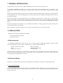
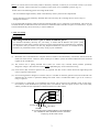
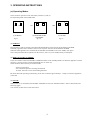
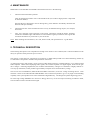
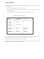
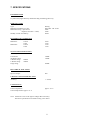
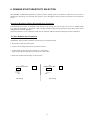
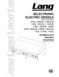
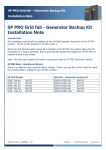
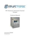
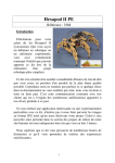
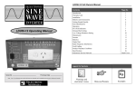
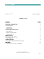
INVERT-A-POWER
INVERT-A-POWER
SPI 1200i-12SS
12VDC TO 240VAC
POWER INVERTER
OWNERS' MANUAL
CONTENTS
PAGES
1. GENERAL INTRODUCTION
2
2. INSTALLATION
2
(a) Environmental
2
(b) Electrical Wiring
2
3. OPERATING INSTRUCTIONS
4
(a) Operating Modes
4
(b) Battery Voltage Out of Range
5
(c) Other Shutdown Modes
5
4. MAINTENANCE
6
5. TECHNICAL DESCRIPTION
6
6. FAULT FINDING
7
7. SPECIFICATIONS
8
8. DEMAND START SENSITIVITY SELECTION
9
9. WARNING
10
10. PRODUCT WARRANTY CONDITIONS
10
Selectronic Australia Pty Ltd
25 Holloway Drive, Bayswater, Victoria, 3153
Rev 1
1. GENERAL INTRODUCTION
Congratulations on your wise choice of this 1200 Watt Selectronic Silver Series Power Inverter.
The INVERT-A-POWER range allows you to operate a variety of 240 volt AC appliances from a 12 volt battery. This
is achieved by electronically converting a low voltage direct current (DC) into a higher voltage alternating current
(AC).
Reliable short term intermittent (or surge) power is available from these models, which is sufficient to start 4600 Watts
of total appliance load. Inverter operating times for various load powers are tabulated in the Specifications section of
this manual on page 8.
Please note that there are some appliances that are not suitable for operation from a power inverter. Note also that,
when using compact fluorescent lamps, good quality lamps should be chosen, to ensure high reliability and high
efficiency If you have any queries about suitable appliances, please contact your INVERT-A-POWER agent for further
advice.
Because of the high power capabilities of your INVERT-A-POWER, we strongly suggest that you take particular note
of the installation steps in this manual.
Please remember to complete all details on your warranty card and return it to us as soon as possible.
2. INSTALLATION
Installation is best approached under two headings:
(a) Environmental considerations
(b) Electrical wiring
(a) Environmental
An INVERT-A-POWER has internal circuitry that is closely related to a HIFI audio amplifier. However, unlike
most audio amplifiers, inverters are often exposed to some or all of the following hazards:
- Moisture (possibly salt laden)
- Dust
- Temperature extremes
- Battery acid fumes
- Generator exhaust fumes
- Nesting animals
To help protect your investment, try to minimize the above factors if at all possible Also, choose a position that will
allow some natural cooling for the inverter The heatsink at the rear should ideally be placed in a position where heat
can easily disperse through natural convection.
(b) Electrical Wiring
In general, we strongly advise that all electrical installation work should be carried out by a qualified electrician.
1. Low Voltage DC Wiring
It is of vital importance to keep battery connectors and terminals in good condition, since very large electric currents
are involved. Loose connections or faulty battery cells can allow excessive voltages during charging and damage to the
inverter could occur.
2
Before you connect the inverter battery leads to the battery terminals, we advise you to turn OFF switch ±1 (as shown
in fig 3.3 overleaf). When connections are complete, return switch 1 to its NORMAL position (fig 3.1).
Please observe the following points concerning the DC leads:
- Do not extend the length of battery leads or the efficiency of the system will be compromised.
- Wiring between inverter and battery should be direct (do not fit any DC switching devices such as relays or
changeover switches).
It is suggested that the battery leads be twisted around each other prior to connection to the batteries. This action can
lower the amount of radiated electrical noise which can sometimes affect AM radio reception on weak stations. A good
external AM aerial may also be necessary in some installations.
2. 240V AC Wiring
WARNING The voltage from an inverter is just as lethal as land line power.
It is therefore absolutely necessary for your safety, to ensure that all Remote Area power system
installations meet and comply with the relevant provisions and requirements of AS3000 wiring standards.
It is imperative that you ensure also that only Registered Electrical contractors or licensed electrical
mechanics are permitted to install or check any wiring in your installation.
When installing this inverter or tracing wiring faults, be aware of the following:
(i)
Both 240V active and neutral have complete electrical isolation from both battery connections and also from the
metal case of the inverter. However, when wired up as an "MEN" system, the Neutral and Earth can be connected
together at the switchboard.
(ii) The inverter uses a pulsing demand start system (see section 3(a) overleaf) which produces potentially
dangerous voltages. Disconnect the inverter before undertaking any work on the mains wiring.
(iii) Power factor (PF) correction capacitors are not required with this inverter. Check fluorescent light fittings and
remove capacitors where fitted.
(iv) If an inverter/generator changeover switch is used, it is vital that AC from the generator must not be allowed to be
fed back into the inverter or permanent damage will result. Thus a "break-before-make" type of AC switch (or
relay) is required.
(v) Occasionally it is found that, in an installation, the inverter will not return to the "Standby" mode. In such cases,
the sensitivity of the demand start system may have to be reduced. This will require access to the circuit board,
and the procedure for this adjustment is outlined in Section 8 of this manual.
RED
GRN
BLK
ACTIVE
NEUTRAL
EARTH
Recommended 240V HARD WIRING AND EARTHING
For a REMOTE AREA POWER SUPPLY SYSTEM
Employing an SPI 1200i-12N/S
3
3. OPERATING INSTRUCTIONS
(a) Operating Modes
Three modes of operation can be selected by switches (1) and (2).
Each operating mode is described below.
1
2
ON
OFF
(1) NORMAL
fig 3.1
1
ON
2
1
ON
OFF
(2) DEMAND START
OVERRIDE
fig 3.2
2
OFF
(3) ON/OFF
fig 3.3
(1) NORMAL
Most appliances will be sensed by this advanced Demand Start system used in this INVERT-A-POWER.
Generally, appliances that consume at least 4 watts of power will start this INVERT-A-POWER.
When all of the appliances are switched off, the INVERT-A-POWER reverts to the standby state again.
This is the preferred mode of operation for the inverter, with a very low standby battery consumption.
(2) DEMAND START OVERRIDE
In the rare instances where the INVERT-A-POWER remains in the Standby Mode even when the appliance switch is
turned on, you may need to override the demand start via switch (2).
Other situations where this may be useful include:
- Power tool operation
- For continuous operation of timing mechanisms
in VCRs, microwave ovens and washing machines.
Be aware that when operating continuously, the inverter consumes approximately 1.7 Amps even with no appliances
connected.
(3) ON/OFF
When switch (1) is turned OFF, the INVERT-A-POWER is reset from shutdown modes 1 and 5 as described in the
following pages.
Turn switch (1) back ON to restart the inverter.
4
(b) Battery Voltage Out of Range
An internal buzzer warns you if the battery voltage is either too low or too high. The sound produced is an interrupted
tone that continues until the situation is corrected.
(1) Low Battery Voltage Shutdown
If the amount of energy that has been removed from your batteries causes the terminal voltage to drop below
approximately 10.0 volts, the internal alarm buzzer will produce an interrupted tone, and the inverter will switch off.
Note that the battery voltage is able to drop below 10 volts briefly to facilitate the starting of motors and other
appliances that have a high surge requirement.
The buzzer will continue to sound until either:
(i)
The batteries are recharged to approximately 13 volts, at which point the inverter will automatically
restart and the alarm tone will cease.
or:
(ii)
ON / OFF switch (1) is briefly turned OFF then back ON.
(2) High Battery Voltage Shutdown
To protect the inverter and your appliances, the inverter shuts down if the battery voltage exceeds approximately 15.5
volts. To restart, the voltage must be reduced to approximately 14.5 volts.
(c) Other Shutdown Modes
Since this inverter has been designed to operate over a wide range of power levels, there are a number of inbuilt
protection devices to prevent excessive internal temperatures from occurring.
(1) High Internal Temperature
If the temperature inside the inverter exceeds approximately 45° C, the fan is activated. If the internal temperature
continues to rise above 70° C, the inverter will switch itself off until it cools sufficiently.
(2) High MOSFET Temperature
During medium to high power operation, this shutdown mode may occur. For example, after approx. 1 minute from
25° C at 3000 Watts, the output voltage of the inverter will be reduced to allow the
power switching devices (MOSFETs) to cool down.
(3) Reactive Load Over-temperature
If the appliance load has an excessive reactive component, for example, large capacitance and/or inductance, the
INVERT-A-POWER will shut itself down due to high MOSFET temperatures, then restart on cooling.
(4) Over Current Protection
This protection system prevents overloads from occurring when for example, motors and incandescent lamps are
started. If an excessively large load is switched on (an extreme case is a short circuit), the maximum current that is
permitted to flow is set at 450 Amps DC.
(5) Short Circuit Output
For safety purposes, the inverter will shut down completely after approximately 10 seconds if the AC output is short
circuited.
This will also occur if the AC voltage drops to less than 140 volts RMS. The internal buzzer will emit a continuous
tone under this shutdown mode. This situation is covered in more detail in the “Fault Finding” section of this manual.
5
4. MAINTENANCE
Maintenance on the INVERT-A-POWER is minimal and consists of the following:
1.
Check for unobstructed fan operation:
Clear any dust/foreign matter with a soft bristled brush. (Do not direct high pressure compressed
air at the fan blades)
Note that the fan is designed to come on during heavy power demand. Periodically check that the
fan starts and spins smoothly.
2.
Check between fins of the heatsink and clean out any accumulated foreign objects, for example,
insect nests.
3.
Carry out a thorough visual inspection of all wiring, particularly around the battery terminals.
Connections should be tight with minimal corrosion. Please regard your batteries with a great deal
of caution and entrust any such work to your electrician.
Note: When cleaning external surfaces, use a soft, lint free cloth, with polish and wax. e.g. Mr Sheen.
5. TECHNICAL DESCRIPTION
The following description is not comprehensive enough to be used as a service manual, but is a brief introduction to the
theory of operation of this particular power inverter.
The majority of the electronic components are located on a double-sided printed circuit board measuring 274mm by
177mm which is lacquered to minimize the penetration of moisture.
As stated previously in this manual, a power inverter of this design operates in a similar fashion to a very high powered
audio amplifier. Rather than amplifying audio signals, this inverter amplifies two digital signals, known as the gate
drive voltages. Following amplification, the resultant switched battery voltages are combined in a highly efficient Ccore step-up transformer, which produces approximately 340 peak volts at nominal battery voltage.
This inverter uses 26 MOSFETs (Metal Oxide Field Effect Transistors) as the low voltage switching devices. Each
transistor consists of around 4400 individual MOSFET cells connected in parallel to give a very high current handling
capability. This system produces low losses and therefore high efficiency. The design also permits high surge power.
Six more high voltage MOSFETs are used in an "Energy Recovery" circuit for improved running of inductive loads,
such as induction motors and fluorescent lights.
6
6. FAULT FINDING
If your INVERT-A-POWER appears to be malfunctioning, we suggest that you follow the steps below so that you can
isolate the problem.
1.
Set switches 1 and 2 to NORMAL as shown in fig 3.1 on page 4.
2.
Turn ON one of the GPOs (power point) which will activate the respective neon indicator when AC voltage is
present (see * below)
3.
Operate appliances and observe the INVERT-A-POWER behaviour as summarised below:
SUMMARY OF INVERTER STATUS:
BUZZER/
NEONS
INVERTER STATUS
(if applicable)
REMEDY
GPO NEON
FLASHING *
Standby mode
GPO NEON
CONTINUOUSLY
LIT *
Normal Running
BUZZER WITH
CONTINUOUS
TONE
Appliance load
too large
Reduce total load
then reset with
Switch 1
BUZZER WITH
BROKEN TONE
Battery voltage
out of range
Refer to Page 5
for details
By consulting the above table, you should be able to determine whether there is a fault in your installation. If you are
having problems that you are unable to solve, we advise you to contact your agent for help.
Please note that there are no user-serviceable fuses within this inverter.
If for any reason, you need to return your INVERT-A-POWER to your agent, we prefer that you use the original carton
and packing material. Therefore, do not dispose of the carton.
7
7. SPECIFICATIONS
INVERTER TYPE
Crystal locked, high efficiency PWM switching with Energy Recovery.
DEMAND START
Type:
Minimum Load Power to start:
Maximum wiring - capacitance:
length (2.5mm twin + earth)
Standby current from battery:
Pulsing
Selectable 4W or 8W
0.2uF
250m
60mA
BATTERY VOLTAGE RANGE
MinimumMaximum-
Cutout:
Cutin:
Cutout:
Cutin:
10.0V
12.5V
15.5V
14.5V
TOTAL APPLIANCE RATING
(at 25 °C)
Continuous:
30 Minute rating:
5 Minute rating:
1 Minute rating:
Surge rating:
1200W
1450W
2200W
3200W
4600W
ELECTRICAL ISOLATION
Input to Output:
2kV
CRYSTAL OSCILLATOR SECTION
Accuracy:
+/- 0.02%
COOLING FAN
Cutin Temperature:
Cutout Temperature: approx. 35 °C
approx. 45 °C
Note: Selectronic reserves the right to change data if necessary.
The above specifications are based on unity power factor.
8
8. DEMAND START SENSITIVITY SELECTION
This INVERT-A-POWER incorporates a 2 position switch, situated on the circuit board, to enable two pre-set levels of
demand start sensitivity to be selected. This switch is set to the highest sensitivity position (4 Watts of AC load) at the
factory.
Situations Requiring Reduced Demand Start Sensitivity
In installations that involve an unusually large amount of AC wiring, the inverter may not revert to its standby mode
even when all appliances are turned off. This is usually caused by high wiring capacitance which the inverter cannot
distinguish from a small appliance.
Check also that there are no "phantom" loads, such as small DC adapters which will keep the inverter switched on.
To Alter Demand Start Sensitivity
WARNING: This procedure should be carried out by a licensed electrician.
1. Disconnect at least one battery lead
2. Unscrew all 12 Philips head screws and remove the lid
3. Locate switch S3 near the 2-pin connector J7. If necessary,
bend the front panel outwards to provide access to the switch.
4. Select the required switch setting as shown below.
S3
DEMAND START
0 0 0
2 1
4W
J7
S3
DEMAND START
0 0 0
2 1
8W
4W Setting
8W Setting
9
J7
9. WARNING
The voltage from an inverter is just as lethal as land line power.
It is therefore absolutely necessary for your safety, to ensure that all Remote Area power system
installations meet and comply with the relevant provisions and requirements of AS3000 wiring
standards.
It is imperative that you ensure also that only Registered Electrical contractors or licensed
electrical mechanics are permitted to install or check any wiring in your installation.
10. PRODUCT WARRANTY CONDITIONS
Selectronic Australia Pty Ltd warrants your SPI 1200i-12N/S inverter to be free from defects in
materials and workmanship under normal use and service, for two (2) years.
The warranty is applicable only from the date of original purchase. All parts will be replaced or
repaired free of charge within this period. The unit shall be returned at no cost to the owner.
The provision of this warranty shall not apply if the unit has been subject to misuse, neglect, acts
of God, accidental damage or has been used for a purpose for which it is not designed.
Any alterations or repairs by unauthorised parties will void your warranty.
Freight charges to the point of purchase and the cost of any repairs resulting from damages
occurring during this freighting will be borne by the owner.
To ensure fast efficient handling of any warranty claims, please complete and return your reply
paid warranty card within 30 days from date of purchase.
If service is required, please return your inverter in its original carton with proof of purchase and a
brief description of the fault, to your point of service or any of the following service centres:
Selectronic Australia
25 Holloway Drive
Bayswater
Victoria 3153
Australia
PH 03 9762-4822
Burley TV Service
278 Edmondson Ave
Austral
NSW 2171
Australia
02 606-0279
10
Reid Technology Ltd.
3-5 Auburn Street
Takapuna
North Shore City
Auckland NZ
9 489-8585