1
CT7
Project :
ISSUE
05
DATE
2015-06-15
Ref :UM-CT7-11-001
Page 1 of 53
High Precision
7 wavelengths Coating Test
CT7
USER MANUAL
NAME AND FUNCTION
DATE
PREPARED BY
P. Woszczyk,
2015-06-15
CHECKED BY
D. Malaise,
2015-06-15
QUALITY APPROVED
P.Woszczyk
BY
2015-06-17
APPROVED BY
2015-06-17
D.Malaise
SIGNATURE
T005_Report_i000.dot
This document is OPO property. It may not be either used or copied without authorization.
OPO sprl, Crawhez 9, 4890 Thimister Clermont, Belgium. +32 87688989- +32 87598990
Ref :UM-CT7-11-001
Issue : 05
Date : 2015-06-15
Page 2 of 53
Document Change Log
Issue
Date
1
2011-04-14
2
2012-10-15
3
2014-07-10
4
5
Modified
Pages
Rationale
Document Creation
Applicable for Instruments:
SN : 10001, 10002, 10003,10004, 10005,
Software versions:
CT7_DSP:
v 1.0.2 built 2011-04-28
CT7 OLED
v 1.0.2 built 2011-04-29
CT7 Console
v 1.00 built 2010-05-01
and later.
All
Start-up procedure
CT7-Console description
New functions
Battery management
New version of CT7 Console Software
New version of CT7 DSP firmware
Applicable for Instruments SN: 12006-and later
Software versions:
CT7_DSP:
v 1.2.02 built 2012-09-25
CT7 OLED v 1.2.02 built 2012-09-21
CT7 Console v 1.2.01 built 2012-09-30
and later.
Improved performances
Minor changes in menus
Specification ( Annex 1)
New, high precision, optical head.
Applicable to instrument 120000 and later with Precision Optical
Head
Applicable for firmware:
CT7_DSP:
v 1.3.05 built 2014-05-21
CT7 OLED
v 1.2.11 built 2014-05-16
CT7 Console
v 1.3.00 built 2014-05-02
and later.
2014-08-25
Firmware
upload
procedure added
Idem.
2015-06-15
Introduction
Battery
PowerOn procedure and Battery Maintenance Chapters:
CT7_DSP:
v 1.5.00 built 2015-06-15
CT7 OLED
v 1.2.11 built 2014-05-16
CT7 Console
v 1.5.00 built 2015-06-15
and later.
of
Li-Ion
This document is OPO property. It may not be either used or copied without authorization.
OPO sprl, Crawhez 9, 4890 Thimister Clermont, Belgium. +32 87688989- +32 87598990
Ref :UM-CT7-11-001
Issue : 05
Date : 2015-06-15
Page 3 of 53
Table of Contents
1
OBJECTIVE
4
2
SCOPE
4
3
THE CT7 INSTRUMENT
5
3.1
3.2
4
4.1
4.2
4.3
5
5.1
5.2
5.3
6
Introduction
CT7 Features brief
5
6
CT7 CONCEPTS
7
Quick Start. First measurement.
CT7 design protects telescope mirror
CT7 instrument interfaces
7
9
12
CT7 OPERATION
13
CT7 description
CT7 basics
Working with menus
13
14
15
CT7 MENU REFERENCE
16
6.1
6.2
6.3
6.4
6.5
One Click menu
Measure menu
Report menu
Service menu
Factory menu
16
17
19
21
23
7
CT7-CONSOLE
24
7.1
7.2
8
8.1
8.2
8.3
8.4
9
Installation
CT7-Console reference
MAITENANCE
Soft Calibration Target values
Calibration
Battery
CT7 Firmware update
DELIVRABLES
24
27
40
40
41
43
46
49
10 ABRÉVIATIONS
49
11 ANNEX 1 - CT7 CHARATERISTISC
50
12 ANNEX 2 - TROUBLESHOOTING
51
13 ANNEX 3 - CONFIGURATION FILE (EXPORT/IMPORT)
52
14 ANNEX 4 - SUPPORT
53
This document is OPO property. It may not be either used or copied without authorization.
OPO sprl, Crawhez 9, 4890 Thimister Clermont, Belgium. +32 87688989- +32 87598990
Ref :UM-CT7-11-001
Issue : 05
1
Date : 2015-06-15
Page 4 of 53
Objective
This document provides description of CT7 reflectometer/scatterometer to the depth necessary for the user to
effectively work with the instrument.
2
Scope
This document is applicable for the instrument model manufactured since 2015. The operation in Normal mode
(end-user) is described.
This document is OPO property. It may not be either used or copied without authorization.
OPO sprl, Crawhez 9, 4890 Thimister Clermont, Belgium. +32 87688989- +32 87598990
Ref :UM-CT7-11-001
Issue : 05
3
3.1
Date : 2015-06-15
Page 5 of 53
The CT7 instrument
Introduction
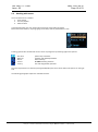
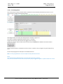
The CT7 is dedicated to monitoring of the coating’s quality of the high grade optical surfaces.
In essence, CT7 is an optical caliper that can be set to fit your laboratory measurements and repeat them at the
remote telescope mirror location.
The current model takes benefit of new high precision optical head providing repeatability of 0.01% (short
term).
CT7 measures the specular reflection and scattering using seven wavelengths spanning from UV to near IR.
Measurements are performed with a countdown of few seconds, enabling gently placement of the instrument
on the precious mirror surface.
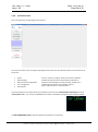
Configurations of the instrument and data retrieval are facilitated by PC application CT7 Console.
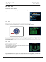
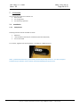
Daniel Malaise demonstrating CT7 at AMOS premises.
This document is OPO property. It may not be either used or copied without authorization.
OPO sprl, Crawhez 9, 4890 Thimister Clermont, Belgium. +32 87688989- +32 87598990
Ref :UM-CT7-11-001
Issue : 05
3.2
Date : 2015-06-15
Page 6 of 53
CT7 Features brief
3.2.1
CT7 Instrument
1.
2.
3.
4.
5.
6.
7.
8.
9.
10.
11.
12.
13.
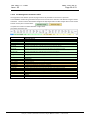
CT7 measures optical reflection and scattering at 8° incidence for 365 to 970nm in 7 bands
The measurement is performed with instrument standing on the measured mirror.
The results are displayed and stored to non-volatile memory.
CT7 may be calibrated to user supplied reference targets (“soft” mirror and scattering target values)
All measurements are time-stamped thanks to the real time clock.
CT7 is built to protect the measured mirror.
An USB connection allows for data retrieval to PC.
All CT7 functions are available from PC and/or from instrument front panel
CT7 may operate without batteries on the USB power
The instrument has three power modes: ACTIVE, SLEEP and CHARGE.
Auto OFF feature protects the batteries against accidental discharge.
Two parallel Li-Ion cells , 14500-size (~AA)size, power the instrument.
Charging of AA cells is primarily performed by built-in charger powered from USB connector of the PC ,
thus charge current is limited to 500mA
14. Charge is performed only when CT7 is not active
3.2.2
CT7 Console software
Small display and simple joystick as data entry interface is definitively not adequate to enter texts, names and
figures necessary for user friendly options of CT7. For this reason, a PC based interface application CT7-Console
was created.
The main purpose of this application is:
1. Data retrieval
2. CT7 configuration
3. CT7 laboratory operation
CT7-Console provides following functions:
1.1. USER level instrument control
1.1.1. Data retrieval and handling of measurement results (export).
1.1.2. Device management by user: configuration view, diagnosis, and up- and down-load of the user
configuration (Measurements Carts: named series of measurements).
1.1.3. Calibration to reference target sample values
1.1.4. Firmware update
1.2. PROCESSING
1.2.1. Sorting and saving data (*)
1.3. EXPERT level instrument control (not recommended for standard user)
1.3.1. Setting and testing the device at the factory.
1.3.2. Down- and up-load factory configuration.
1.3.3. Manage LED driver parameters
(*) the exported data are saved in .csv format ( Excel compatible), so further data processing and graphical
presentations can be done with specialized software.
This document is OPO property. It may not be either used or copied without authorization.
OPO sprl, Crawhez 9, 4890 Thimister Clermont, Belgium. +32 87688989- +32 87598990
Ref :UM-CT7-11-001
Issue : 05
4
Date : 2015-06-15
Page 7 of 53
CT7 Concepts
4.1
Quick Start. First measurement.
Note: CT7 is designed as instrument not requiring frequent calibration. Nevertheless, we recommend verifying
the validity of calibration after delivery and when instrument is subjected to important temperature change.
Simply measure the Calibration Target provided with the instrument. If the obtained differences are within
0.1%, the calibration is valid.
The CT7 is normally in sleep mode and can be awakened by pressing both: the ON Button on the top
of the instrument and navigation switch up.
Power ON
POWER
At the first Power ON , if necessary, the instrument prompts for time setting. (Only when the time
introduced, CT7 is ready for the measurements.)
CT7 is ready to perform quick “One click” measurement with the active Cart of wavelength selection.
By default, the NORMAL measurement configuration is active i.e. 7 bands in Reflectivity and Dust
The MEASURE option is highlighted and may by triggered when pressing the joystick (Enter).
Trigger the measure still keeping CT7 in your hand : you have 5 seconds to place the
instrument gently on the mirror.
After the measurement, the results are displayed and stored with the time stamp and Cart ID.
Pressing joystick (ENTER) returns to the menu.
The measurements are performed as specified by a user’s Cart indicating the wavelengths and type of
measurements to be performed and bearing an identifier. The user can create and select as many Carts as
needed( 64). Carts are created or suppressed from PC application CT7-Console. The new instrument comes with
a default permanent Cart list starting with NORMAL that provides all measurements at all wavelength.
This document is OPO property. It may not be either used or copied without authorization.
OPO sprl, Crawhez 9, 4890 Thimister Clermont, Belgium. +32 87688989- +32 87598990
Ref :UM-CT7-11-001
Issue : 05
4.1.1
Date : 2015-06-15
Page 8 of 53
Single measurement in brief
In current use the measure sequence is following:
4.1.2
Power up CT7 (Press ON button and joystick UP)
Keeping it in hand, go to MEASURE option and trigger it. You have 5 seconds
before the measurement starts (with on-screen countdown)
Place CT7 gently on the mirror
When the measurement is finished, and the results show-up, pick up carefully CT7
Perform your measurements repeating the above steps
Once in the office, connect to PC , run CT7-Console and power-up CT7, activate
SERVICE/PC-Link mode
Retrieve data from CT7 to archive file
Sort data by date, by cart, than export to Excel and finish your report with usual
edition tools
Professional work-flow
Install CT7 Console provided on CT7 Flash Disk on your PC, and start it
Connect CT7, awake it and activate SERVICE/ PC-Link mode
Indicate the COM port to be used (at first connection)
Open Measurement Configuration Management
Read Configuration from CT7
Edit table: selecting wavelengths to be used and give names to CARTs for specific
mirrors. The CART name will help you to sort-out the data for specific mirror.
Write Configuration to CT7
Disconnect by closing CT7-Console
Now you are ready to monitor the mirrors. Select the active CART in menu
MEASURE/ Sel. Cart. Perform your measurements following single measurement
flow
Notes:
You may always review results using menu Report/Data of CT7
This document is OPO property. It may not be either used or copied without authorization.
OPO sprl, Crawhez 9, 4890 Thimister Clermont, Belgium. +32 87688989- +32 87598990
Ref :UM-CT7-11-001
Issue : 05
4.2
4.2.1
Date : 2015-06-15
Page 9 of 53
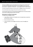
CT7 design protects telescope mirror
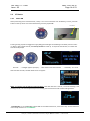
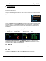
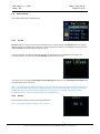
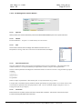
Contact of CT7 with telescope mirror
As the instrument measures specular reflectivity, its angular position with respect to the normal to the mirror’s
surface must be exact, and this can only be achieved by a three point isostatic contact. The actual contact is
provided by three spherical touching feet made out of white Teflon. Teflon can in no way mark the mirror’s
substrate, but it can mark the coating especially if rubbed. The delayed start allows the operator to lay gently
the CT7 on the mirror after starting the measurement and remove it after measurement without the need to
touch it while it sits on the coating. Moreover, the small incidence angle of the measuring beams makes the
result little sensitive to the measurement distance so that the instrument can stand on an optical tissue. This
tissue (paper or cloth) must provide an opening for the beam (25 mm hole) and should be of equal thickness
(+/-0.05 mm) under the three feet.
Black
cavity
Reflected
beam
Input beam
Mirror
Optical scheme of CT7
Taking a measurement with mirror protecting tissue.
This document is OPO property. It may not be either used or copied without authorization.
OPO sprl, Crawhez 9, 4890 Thimister Clermont, Belgium. +32 87688989- +32 87598990
Ref :UM-CT7-11-001
Issue : 05
4.2.2
Date : 2015-06-15
Page 10 of 53
Delayed Start
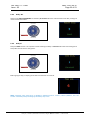
By default, triggering “measure” option invokes a 5 seconds delay before the measurement actually starts.
The objective of this feature is protection of the mirror. The user can set-up and trigger the measurement still
holding CT7 in his hands. When everything is ready, he may carefully place it on fragile telescope mirror,
avoiding rubbing of the surface.
The remaining time before measurement is indicated by a countdown on the display and a beep every second.
The delay timer may be set to a value between 0 and 99 seconds.
Count down: 5 seconds before the measurement becomes RED
The time-to-measure is color coded:
BLUE – more than 5 seconds to measure
RED - less than 5 seconds
YELLOW star (*)– measurement in process
GREEN -results table – measure done.
/see the full sequence – para 6.1.1 MEASURE /
This document is OPO property. It may not be either used or copied without authorization.
OPO sprl, Crawhez 9, 4890 Thimister Clermont, Belgium. +32 87688989- +32 87598990
Ref :UM-CT7-11-001
Issue : 05
4.2.3
Date : 2015-06-15
Page 11 of 53
Wavelengths selection: Carts and Customized measurements
The user can select 0 to 7 wavelengths to be used for measurement of reflection and 0 ..7 for scattering.
However, at least one wavelength shall be selected either in reflectivity or in scattering.
Once customized, given configuration may be named and saved.
User can store up to 64 named Carts of customized measurements. The Carts are created, deleted and edited
from CT7-Console. /see para 4.3.2. PC Software: CT7 Console /
The aim of the Cart operation is the following: assuming that the user has a number of telescopes to monitor
and that each of them has several mirrors, he can prepare dedicated Cart for each mirror .
Cart selection list: R-reflection measurements, D- DUST measurements
Even after a long time, without noting anything, the user unloading the CT7 memory in its PC will be able to
extract all measurements pertaining to any mirror of a particular telescope and trace its evolution with time
(through the date and time attached to each measurement). In this example, we have chosen to select the
same measurement sequence for each mirror of the same telescope but this is not requested.
The Cart operation is a powerful and simple way of keeping order and uniformity among measurements on the
long term.
This document is OPO property. It may not be either used or copied without authorization.
OPO sprl, Crawhez 9, 4890 Thimister Clermont, Belgium. +32 87688989- +32 87598990
Ref :UM-CT7-11-001
Issue : 05
4.3
4.3.1
Date : 2015-06-15
Page 12 of 53
CT7 instrument interfaces
Viewing the results
The user can recall the results by selecting the View Results option. The most recent results are displayed first,
and can be scrolled back and forward with the joystick.
4.3.2
PC Software: CT7 Console
The PC software is described in section 7 CT7-Console .
The main functions are:
4. Data retrieval
5. CT7 configuration
6. CT7 laboratory operation
4.3.3
Display
CT7 is menu operated. Menu system is inspired by DSLR cameras.
On the left side of the display, there is a category menu with pictograms, on the right side, for selected
category, a sub menu presents text options.
In contradiction to LCD displays, this active organic LED display is fully operational in negative temperatures.
4.3.4
Joystick/Navigation Switch
The user selects options from the menu, thanks to a 5 position joystick (left- right, up – down, Enter =OK).
In addition, the joystick provides the Power-On function.
4.3.5
Beep
The operations are confirmed by a short acoustic beep.
4.3.6
USB connector
This is a data interface and an integrated battery charger power connection.
W connected to a PC, it will provide power for battery charging and give access to the PC operation of the
instrument when the latter is set to PC-link mode.
4.3.1
Battery protection –switch off at low voltage
Battery is protected against uncontrolled discharge, potentially destructive.
If left unattended, the CT7 will switch OFF after programmed time of 1 to 10 minutes.
In operation, before any action, the battery voltage is measured. If the voltage is dangerously low, after a series
of 5 beeps, CT7 will switch off.
This document is OPO property. It may not be either used or copied without authorization.
OPO sprl, Crawhez 9, 4890 Thimister Clermont, Belgium. +32 87688989- +32 87598990
Ref :UM-CT7-11-001
Issue : 05
5
5.1
Date : 2015-06-15
Page 13 of 53
CT7 Operation
CT7 description
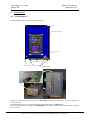
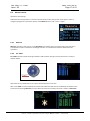
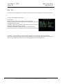
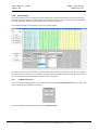
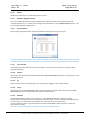
The following drawing shows the main features of CT7:
Cover
Command 5 place joystick
UP
ASTRO COATING MONITOR
Dust scattering
LEFT
Specular
reflectivity
ENTER
RIGHT
DOWN
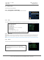
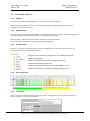
7 bands from 365 nm to 970 nm
Tycho M3 09-17-2011
REFLECTIVITY
365 nm:
405 nm:
464 nm:
522 nm:
624 nm:
760 nm:
970 nm:
76.4%
84.7%
91.9%
93.7%
94.2%
79.4%
92.8%
DUST
7.5
5.0
3.2
2.8
2.0
1.3
0.7
Display screen
www.opo.be
Measurement aperture
Protection pads
Positionning pads
CT-7 Instrument.
LEDs: CHARGE-STAND BY-ON
Reset
ON button
Serial
USB
On the top cover you find an access for the <mini USB-B> connector for connection CT7 to a PC (power and
data connection).
On the back side, there is a 1 mm hole that gives a protected access to a RESET switch.
Also on the back side you may find the Serial Number of the instrument. The same number is returned by soft
to CT7 Console.
This document is OPO property. It may not be either used or copied without authorization.
OPO sprl, Crawhez 9, 4890 Thimister Clermont, Belgium. +32 87688989- +32 87598990
Ref :UM-CT7-11-001
Issue : 05
5.2
Date : 2015-06-15
Page 14 of 53
CT7 basics
5.2.1
Power ON
When performing actual measurements, usually CT7 is not connected to a PC. On Battery, to start, press ON
button on the top of the CT7 and simultaneously push the joystick UP
ON button
Power ON
POWER
Pressing shortly joystick will toggle the supply ON (green LED lights immediately) and initiate processor startup. After a delay of few seconds, the Start-up screen will show up. A couple of seconds later, CT-7 date and
time will be displayed.
Press UP
.. backlight appears promptly … Start Screen a few seconds later … end finally .. the Time.
After next few seconds, the ONE CLICK menu will appear.
NOTE: It is vital to set correctly the date and time. If the date and time is not set, the result indexing is not
working corrctly. The CT7 will prevent you from making the measurements and communicating with PC.
Time NOT SET >> Go to MEASURE / DATE TIME and set date and time or, much easier way: set the date from
user friendly interface of CT7-CONSOLE.
This document is OPO property. It may not be either used or copied without authorization.
OPO sprl, Crawhez 9, 4890 Thimister Clermont, Belgium. +32 87688989- +32 87598990
Ref :UM-CT7-11-001
Issue : 05
5.3
Date : 2015-06-15
Page 15 of 53
Working with menus
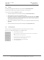
The CT7 Interfaces are limited to
1. Color Display
2. Five way Joystick
3. USB connector
In the field operation, the user selects options from the menu with the joystick.
Most of the customization, requiring typing of text data, shall be performed from a PC.
Pressing joystick LEFT activates left column menu of pictograms representing higher level options:
One Click
Measure
Report
Service
Factory
fastest way to measure
measure and related parameters
data reviewing
PC LINK and utility functions
test and configuration functions
Once the required menu is selected, pressing ENTER/OK opens the list of the lower level options on the right
side.
The following paragraphs explain the available functions.
This document is OPO property. It may not be either used or copied without authorization.
OPO sprl, Crawhez 9, 4890 Thimister Clermont, Belgium. +32 87688989- +32 87598990
Ref :UM-CT7-11-001
Issue : 05
6
Date : 2015-06-15
Page 16 of 53
CT7 Menu reference
6.1
One Click menu
Easy operations without settings.
This menu is initiated by awakening the instrument; one can return to this menu from another one by pressing
the joystick LEFT and selecting the first menu in the left column with the Up and DOWN positions of the
joystick.
6.1.1
MEASURE
At power up MEASURE is highlighted on the One Click screen: you are ready to perform a measurement using
the last CART selected , or by default NORMAL. Press OK to initiate the measurement. During “time delay”
seconds you shall position the instrument on the mirror before the measurement actually starts. (see also
6.4.3 Delay ms ).
The time to measure is counted down on the screen (blue figures).
5 seconds before the measurements the color changes to red.
During the measurement a yellow star is displayed.
The following screens illustrate the sequence:
-
Countdown “Blue”
- Countdown “Red”
- Measure in process
- Results
Press ENTER to go to the next measurement. Screen ONE CLICK appears and you can continue making
successive measurements; you can also shift to Meas.*10 or to Low noise type of measurement by selecting
the one you want with up and down strokes of the joystick.
6.1.2
Meas.*10
CT7 performs and memorize the basic measurement 10 times and displays the last one on the screen.
6.1.3
Sleep
The last place on the One Click menu is Sleep . Entering Sleep will shut down the instrument.
This document is OPO property. It may not be either used or copied without authorization.
OPO sprl, Crawhez 9, 4890 Thimister Clermont, Belgium. +32 87688989- +32 87598990
Ref :UM-CT7-11-001
Issue : 05
6.2
Date : 2015-06-15
Page 17 of 53
Measure menu
Operations with settings
Selected as the second position in the list on the left of the screen; then go back to the right in order to
navigate among the four operation options of the Measure menu. (Left – Down – Right)
6.2.1
Measure
Measure operation is the same as on the One Click menu. Before start of a measurement, the operator is
prompted for selection of CART for wavelength selection. The selected Cart becomes default for later
operations.
6.2.2
Sel. CART
Sel. CART operation allows selecting as default a CART without making a measurement from a list of predefined CARTS.
Previous
Press-ENTER :
to validate
Next
New CARTs or any modifications can only be introduced from CT7 Console.
After a new CART has been selected, the measurement with this CART can be immediately initiated from the
same menu by entering Measure (one Up). When the measure is finished, the result is shown in Data View
This document is OPO property. It may not be either used or copied without authorization.
OPO sprl, Crawhez 9, 4890 Thimister Clermont, Belgium. +32 87688989- +32 87598990
Ref :UM-CT7-11-001
Issue : 05
6.2.3
Date : 2015-06-15
Page 18 of 53
Date Time
Date Time operation allows setting or resetting the date and the time. Pressing the joystick LEFT activates
setting and entering the selected values (red highlight).
Increment
Previous
Next
Press-ENTER :
to validate
Decrement
Pressing ENTER finish the date and time edition – red highlight disappears.
Pressing ENTER again, takes us back to MEASURE menu.
Note: There is button COPY PC-Time to CT7 (on CT7 Console / Device Management panel) allowing one to copy
PC time and date to CT in one –click.
6.2.4
Calibrate
Place CT7 at the calibration target (MIRROR), activate menu MEASURE / Calibrate.
Usually calibration is performed when one suspects any pollution or if time elapsed since the last calibration is
estimated too long, or if some measured values are suspect.
The instrument performs calibration in sequence:
1. 5 second countdown,
2. Repeat 8 times the measurement of an known mirror.
3. Compute and display coefficients for proofing.
4. Store in nonvolatile memory.
The reference values and actual coefficients may be read and modified in CT7 Console Device Management
window.
DUST calibration may be conducted only from CT7-Console.
Note: CT7 may be referenced to local calibration values by changing reference target values in CT7 Console /
Device Management, and writing them back to the CT7 instrument. See para. 8.1 Soft Calibration Target
values for details.
This document is OPO property. It may not be either used or copied without authorization.
OPO sprl, Crawhez 9, 4890 Thimister Clermont, Belgium. +32 87688989- +32 87598990
Ref :UM-CT7-11-001
Issue : 05
6.3
Date : 2015-06-15
Page 19 of 53
Report menu
Reviewing data relative to measures
Choose the Report menu by navigating in the left column and entering the selected third place (Left – Down –
Right).
6.3.1
Data
Data operation allows displaying the results that are memorized in the instrument.
The data pertaining to the last measurement are shown upon entering the Data operation.
+ 10
Previous
Next
Press-ENTER :
validate
-10
When the screen shows a measurement data, other measurement can be displayed by navigating with the
joystick: LEFT for displaying the previous measurement, RIGHT for displaying the next, UP will move 10
measurements later, and DOWN ten measurements before the displayed one. Measurements can be identified
by their index and date.
6.3.2
Calib
Calibration coefficients are displayed.
Below the coefficients, there are:
-calibration temperature of reflection channel (for temperature correction)
-date of reflection calibration (Refl: )
-date of dust calibration ( Dust: )
Note: OPO has devised a VW jig allowing direct absolute calibration of a gauge just before using it. This is the
only procedure that allows checking the calibration of the instrument and correcting it if needed.
This document is OPO property. It may not be either used or copied without authorization.
OPO sprl, Crawhez 9, 4890 Thimister Clermont, Belgium. +32 87688989- +32 87598990
Ref :UM-CT7-11-001
Issue : 05
6.3.3
Date : 2015-06-15
Page 20 of 53
Info
This operation will display general information about the instrument as it appears on the screen hereunder.
The list provides following parameters:
Actual CART #
Number of measurements in the memory (since last CLEAR)
Absolute counter of the measurements since assembly of the instrument
Language selected 0=English
Delay after Trigger before start of the actual measurements (in seconds)
Delay before Automatic Sleep (in minutes)
Flash addr – base address of data block in internal FLASH memory
Serial number of the CT7 instrument (same as on the back of the housing)
Flash Addr: - The base address of block of memory actually used . The results, even for hundreds of
measurement, are quite limited in volume: several kilobytes. CT7 changes periodically position of data block
within its huge 2Gbytes flash data memory to avoid (hypothetic) flash memory burn-out.
This document is OPO property. It may not be either used or copied without authorization.
OPO sprl, Crawhez 9, 4890 Thimister Clermont, Belgium. +32 87688989- +32 87598990
Ref :UM-CT7-11-001
Issue : 05
6.4
Date : 2015-06-15
Page 21 of 53
Service menu
User settable parameters and monitoring
6.4.1
PC Link
PC Link operation is used to connect the instrument to a PC. The PC program CT7 Console must run and the
USB connection done before this operation can be executed. The connection is validated by a mark in the case
“PC connected” on the left bottom of the PC screen).
Once this operation has been entered, the autonomous operation of CT7 is disabled (the joystick is not
operating anymore. The display shows UIF LOCKED. (User Interface Locked)
This status can be reversed by closing the CT7 Console program on the PC or by resetting the instrument using
the reset switch at the rear of CT7.
Note: This mode may be used for long term test of CT7, ant the instrument is assumed to be powered by PC via
USB, so the Automatic SLEEP function is disabled. However, some PC with active power saving may shut down
or hibernate after some time, switching off the USB. In such case CT7 will remain ON and heavy battery
discharge may occur. (See “CT7 does not power up” troubleshooting).
6.4.2
Battery
Get the battery voltage and remaining energy estimation.
NOTE: use this percentage as indication, not a measure.
This document is OPO property. It may not be either used or copied without authorization.
OPO sprl, Crawhez 9, 4890 Thimister Clermont, Belgium. +32 87688989- +32 87598990
Ref :UM-CT7-11-001
Issue : 05
6.4.3
Date : 2015-06-15
Page 22 of 53
Delay Ms.
Wait time for Delayed MEASURE. Set the delay in seconds before the measurement starts after pushing the
measurement start button.
Increment
Press-ENTER :
validate
Decrement
6.4.4
Delay Sl.
Delay for SLEEP function. This operation allows resetting the delay in minutes before the instrument goes to
sleep after the last touch to the joystick.
Increment
Press-ENTER :
validate
Decrement
Before going to sleep, a beeping count-down will show for ten seconds.
NOTE: automatic sleep count-down is disabled in following actions: “Status”,” Meas 1/Minute”, and “UIFLocked”. Potentially a deep discharge of the battery may occur!
This document is OPO property. It may not be either used or copied without authorization.
OPO sprl, Crawhez 9, 4890 Thimister Clermont, Belgium. +32 87688989- +32 87598990
Ref :UM-CT7-11-001
Issue : 05
6.5
Date : 2015-06-15
Page 23 of 53
Factory menu
Internal settings and housekeeping.
6.5.1
Francais/English – Language toggle
Choice allows toggling between French and English versions of menus.
6.5.2
Status
This operation displays various household data of the instrument the list of which is on the left of the screen.
Temp1 – Detector temperature
Temp2 – Battery temperature
V0 –LED supply: 8.4V
V1 –DSP supply: 3.3V
V2 –USB supply voltage
V3 -Battery voltage (Li Ion: 3V low – 4.2V Fully Charged)
V4 -Digital Supply: 5V
V5- Analog Supply: 5V
V6 -Aux DSP supply: 3.3V
V7 –DC-DC supply (from battery: or USB)
(*) with poor cable (i.e. V_USB <=4.2V ) charger is not operating correctly.
6.5.3
Meas/1 min
Meas/1 min : the instrument is set to perform and record one measurement per minute in endless loop. The
measurements are done using the active CART. This function is used for performing thermal and battery life
tests.
Note: Automatic SLEEP function is disabled in this mode. Battery discharge may occur if not powered with USB
6.5.4
Version
Display the serial number of the instrument and the versions of the operating software.
There are two software versions.
CT7 is powered by two processors: one for OLED display
handles user interface and a second one, a DSP, for acquisition
and processing.
This document is OPO property. It may not be either used or copied without authorization.
OPO sprl, Crawhez 9, 4890 Thimister Clermont, Belgium. +32 87688989- +32 87598990
Ref :UM-CT7-11-001
Issue : 05
7
Date : 2015-06-15
Page 24 of 53
CT7-Console
The main functions of this PC interface are:
1. Data retrieval
2. CT7 configuration
3. CT7 laboratory operation
7.1
Installation
7.1.1
Components
Following elements shall be installed on the PC:
USB driver
.net Framework necessary for installation (automatic download)
CT7-Console itself
CT7 installer, together with documentation, is provided on a USB Flash Drive.
NOTE: provided USB Flash stick is just a memory to ease the first steps with CT7. CT7 does not require
hardware key for operation. Same contents may be downloaded from support www.
This document is OPO property. It may not be either used or copied without authorization.
OPO sprl, Crawhez 9, 4890 Thimister Clermont, Belgium. +32 87688989- +32 87598990
Ref :UM-CT7-11-001
Issue : 05
7.1.2
Date : 2015-06-15
Page 25 of 53
Win7 (-32 and -64) Installation
The installation is performed in only two steps:
Let Windows7 to find and install USB driver
Run CT-7 Console setup
Now, let’s have a look in details:
Let Win 7 to install driver:
Power ON the CT7 instrument and connect to USB port of the PC - after few seconds the CT7 device will be
available and COM port created (see Hint 3 below).
Install CT7-Console:
Download from http://www.a1pixel.pl/CT7/ct7-download.html the latest version of CT7-Console package,
extract the contents of CT7.zip to yours “My Documents” folder.
A following structure is created:
Go to Install folder and run Setup.
Start using the software.
Do not forget to switch CT7 into PC-Link mode (using it's joystick and menu), select the Communication port
and you may enjoy the connection.
Hints:
1. Setup aborts if a previous installation performed from a different location is detected. Go to Control
Panel/Programs and features, and remove the previous version manually.
2. If the driver is not correctly installed, or CT7 is not connected to PC you will most probably get error "No
Communication Port Available". Windows creates dynamically the port when CT7 is connected (and powered).
3. Typical message during automatic CT7 driver installation:
This document is OPO property. It may not be either used or copied without authorization.
OPO sprl, Crawhez 9, 4890 Thimister Clermont, Belgium. +32 87688989- +32 87598990
Ref :UM-CT7-11-001
Issue : 05
7.1.3
Date : 2015-06-15
Page 26 of 53
Windows XP and Vista (-32) Installation
The installation is performed in only two steps:
Download and install USB driver
Download and Run CT-7 Console setup
The PC shall have internet access for downloading the “.net v 3.5” framework during setup.
Now, let’s have a look in details:
Install driver:
The USB driver shall be installed manually prior to connection of the instrument.
Download from http://www.a1pixel.pl/CT7/ct7-download.html the latest version of CT7 driver, extract from
ZIP and start Setup
Power ON the CT7 instrument and connect to USB port of the PC - after few seconds the CT7 device will be
available and COM port created (see Hint 2 below).
Install CT7-Console:
Download from http://www.a1pixel.pl/CT7/ct7-download.html the latest version of CT7-Console package,
extract the contents of CT7.zip to yours “My Documents” folder.
A following structure is created:
Go to Install folder and run Setup.
If necessary, the ".NET framework" will be automatically downloaded (from Microsoft) during the setup of
CT7 Console.
Start using the software.
Do not forget to switch CT7 into PC-Link mode (using it's joystick and menu: SERVICE/PC-LINK), select the
Communication port and you may enjoy the connection.
Hints:
1. Setup aborts if a previous installation performed from a different location is detected. Go to Control
Panel/Programs and features, and remove the previous version manually.
2. If the driver is not correctly installed, or CT7 is not connected to PC you will most probably get error "No
Communication Port Available". Windows creates dynamically the port when CT7 is connected (and powered).
This document is OPO property. It may not be either used or copied without authorization.
OPO sprl, Crawhez 9, 4890 Thimister Clermont, Belgium. +32 87688989- +32 87598990
Ref :UM-CT7-11-001
Issue : 05
7.2
7.2.1
Date : 2015-06-15
Page 27 of 53
CT7-Console reference
Platform
The software is tested on following platforms: XP-32, Vista-32, Win7-32, Win7-64,
Note: At XP and Vista systems .Net 3.5 is necessary (downloaded from Microsoft-Update www during
installation). Win7 includes .Net 3.5.
7.2.2
USB connection
The USB interface is built around FTDI FT232D chip configured for serial port- on-USB. Windows recognizes this
device and creates virtual COM port when CT7 is connected and switched ON.
Win XP and Vista: USB driver shall be installed manually from Ct7\Install folder
Win7: USB driver is downloaded automatically from Microsoft Update.
7.2.3
CT7 file system
However it is possible to change the folders’ locations at ABOUT panel or with save/open file menus, we
recommend using the following folder structure:
Storage of CT7 instrument’s configuration files (CARTS, parameters)
Folder of User Manual
Folder for exporting data from Instrument (Data Panel)
CT7Console Installation (setup.exe)
Folder for storing Result Archives and results logged from PC
Updates of firmware: CT7_DSP.bin and Display OLED: CT7.bin
7.2.4
Color convention
REFLECTION (data, parameters, config, etc.)- green
7.2.5
DUST (data, parameters, config., etc.) - yellow
Instant Help
The user interface provides instant help. When the coursor is hanging over a function button or dialog for
about 5 seconds, an instant help text appears.
This document is OPO property. It may not be either used or copied without authorization.
OPO sprl, Crawhez 9, 4890 Thimister Clermont, Belgium. +32 87688989- +32 87598990
Ref :UM-CT7-11-001
Issue : 05
7.2.6
Date : 2015-06-15
Page 28 of 53
CT7-Console start
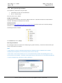
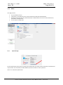
At CT7 Console start, the following screen appears:
The main part of the screen is empty. Following function panels may be called by buttons in the left column of
the screen:
About
Data handling
Measurements configuration
CT7 management
User Manual
/version , authors, program mode, file structure, updates /
/readout of data from instrument, filtering and export /
/selection of wavelength for measurements, editing carts /
/maintenance functions and parameter edition /
/opens .pdf document in a new window/
You should observe in the lower left corner of the PC screen the case “connected/non-connected” shown as
“Connected to CT7”. CT7 must be in SERVICE/PC-link state, indicated by message UIF (user interface) locked,
The DATA MANAGENT panel is fully operational also without CT7 connected.
This document is OPO property. It may not be either used or copied without authorization.
OPO sprl, Crawhez 9, 4890 Thimister Clermont, Belgium. +32 87688989- +32 87598990
Ref :UM-CT7-11-001
Issue : 05
7.2.7
Date : 2015-06-15
Page 29 of 53
About
This page contains
7.2.7.1
Current software version
Information on the software version and manufacturers OPO and A1Pixel address.
Handling of the mode: Normal/ Advanced/ Expert. Mode defines the access to low level functions,
parameters and diagnostics.
CT7 file system configuration
Support www page.
On the support www, which opens up after pressing the button, the latest versions information and download
may be found. The Tech-Notes provides additional, practical answers to users’ questions.
There is no automatic update check.
This document is OPO property. It may not be either used or copied without authorization.
OPO sprl, Crawhez 9, 4890 Thimister Clermont, Belgium. +32 87688989- +32 87598990
Ref :UM-CT7-11-001
Issue : 05
7.2.7.2
Date : 2015-06-15
Page 30 of 53
CT7 File system
The sample file system is given here. Please observe that CT7 folder is not Documents\CT7\.. – you are
absolutely free to keep the files in any folder you wish, even not on the same disk. However in the manual we
describe all operations for the default structure, so it is easier to follow the instructions if you use a similar
structure.
We suggest using such tree:
Storage of CT7 instrument’s configuration files (CARTS, parameters)
Folder of User Manual
Folder for exporting data from Instrument (Data Panel)
CT7Console Installation (setup.exe)
Folder for storing Result Archives and results logged from PC
Updates of firmware: CT7_DSP.bin and Display OLED: CT7.bin
7.2.7.3
Program mode
The difference between program modes is a number of available functions,
specially for CT7 Management.
Normal program mode is typical end-user mode with data management and
houkeeping monitoring functions.
Advanced – additional functions for internal parameters edition are available.
Expert – all features, including factory setup, testing and peripherial devices.
Advanced and Expert modes are not described in this document. In case of need
of in-deep diagnostics instructions will be provided by support team.
This document is OPO property. It may not be either used or copied without authorization.
OPO sprl, Crawhez 9, 4890 Thimister Clermont, Belgium. +32 87688989- +32 87598990
Ref :UM-CT7-11-001
Issue : 05
7.2.8
Date : 2015-06-15
Page 31 of 53
Data handling
This entry initiates a function allowing manipulating the data, retrieving data from the instrument and saving
them into the PC etc. Note that only the data recorded off line in the CT7 are concerned here; data recorded in
PC mode are directly entered in a PC file and do not transit through the CT7.
It is operated through a self-explanatory screen as it appears below.
You have to define and save a folder to keep the data of the CT7 that is connected to the PC; once defined,
each time the same instrument is connected, and it will open the defined folder and if data are read out from
the CT7 new data will be appended to the previous ones in the folder.
7.2.8.1
Reading the results from CT7
In order to read new data from the CT7 you have to push the button Read measurements from CT7. Only new
measurements will be appended to the folder.
Finish the operation and accept the data by pressing Archive results.
This document is OPO property. It may not be either used or copied without authorization.
OPO sprl, Crawhez 9, 4890 Thimister Clermont, Belgium. +32 87688989- +32 87598990
Ref :UM-CT7-11-001
Issue : 05
7.2.8.2
Date : 2015-06-15
Page 32 of 53
Result Filter
For selecting, comparing particular CART results, you should work with Result Selection Filter.
In the left column available results are displayed, in the right one – the selected ones.
To see all results in the file press View All button (green).
Select date range defined in the two dialogs at the top right of Result Selection Filter box :
Select results by their name from a list of available cart names.
The Available list is limited in time between two selected dates. Select data names in the “Available
list” (left box) and toggle them to the Selected list (right box) using the appropriate button in between
the two boxes (>); if you want to select all available data, use the >> button. The reverse buttons are
used to suppress data names from the Select list.
Once you have completed the selection you want, you may inspect the selected data (by pressing
Apply Filter).
Export the selected measurements for further handling by pressing Export Results button.
7.2.8.3
Mini CT7-Management pane
Some most common CT7-Management functions have been mirrored here for your connivance.
Please refer to CT-Management paragraphs for more in-depth description.
Recall last calibration values and dates
Go to CT7 Management to modify any parameter, in particular Target mirror or scattering sample
value
Set the real time clock of CT7 to actual time of PC
Read all parameters from CT7 and save them to a .txt configuration file
Import to CT7 parameters set from a configuration file
Test the quality of USB power source and internal voltages
Go to CT7 Management panel
This document is OPO property. It may not be either used or copied without authorization.
OPO sprl, Crawhez 9, 4890 Thimister Clermont, Belgium. +32 87688989- +32 87598990
Ref :UM-CT7-11-001
Issue : 05
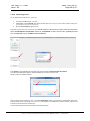
7.2.9
7.2.9.1
Date : 2015-06-15
Page 33 of 53
Working with data
Archive file
The data from the Instrument may be retrieved to the PC and stored to the archive file. This file contains ALL
the measurements retrieved from CT7.
The archive file is watermarked with CT7 serial number so it is not possible to mixt results from different
instruments in one file. On the other hand more than one file may be created for one instrument.
It is possible to work offline with archive file.
7.2.9.2
Data sorting
The viewer of CT-7 console allows sorting data by date and by cart.
7.2.9.3
Exporting data
The selected data lines may be stored in CVS format for further processing in EXCEL.
Eventually a conversion DATA/ Text to columns may be necessary (delimited by tabulation).
Excel provides full interface for graphic data presentation and report creation.
7.2.9.4
Data format
The fields in exported CVS file are separated with tabulation sign.
The record is terminated by a Carriage Return.
Time stamp; Cart; R1; R2; R3; R4;.. R7; S1; S2; .. S7; CR
Note: The user may select or not specific wavelengths for given CART. The results for not used bands are
replaced by a place holder: zero “0”
Where:
Time Stamp yyyy/mm/dd hh:mm:ss
Cart: the name given for selection of wavelength used for this measurement
Rx - reflection for given emitter in %
Sx – scattering (DUST) index for given emitter in %
Decimal separator: dot .
NOTE: In certain countries once .cvs data is uploaded to Excel, the dots shall be replaced by commas before
Excel recognize data as numbers.
This document is OPO property. It may not be either used or copied without authorization.
OPO sprl, Crawhez 9, 4890 Thimister Clermont, Belgium. +32 87688989- +32 87598990
Ref :UM-CT7-11-001
Issue : 05
Date : 2015-06-15
Page 34 of 53
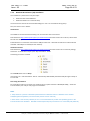
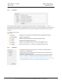
7.2.10 Measurement Configuration
This function allows the user to define modify or cancel measurement CARTs, read the CARTs that are
memorized in the CT7 and load CARTs in the CT7 memory.
These tasks are managed and performed through a graphic interface as shown below.
Loading from an external file
Saving in an external file
Reading from CT
Writing to CT7
The first two commands allow exchanging lists of CARTs between an external folder that you have defined and
a CT7 instrument. This might be useful when several CT7 must work with the same choice of CARTs for
instance.
The last two commands allow exchanging a list of CARTs between the PC and any CT7 instrument.
In the list, each line is a CART for which you may chose a name and select any combination of measurements.
There should be at least one measurement on each CART.
The first CART, NORMAL (# 0) contains all measurement and cannot be modified or removed.
This document is OPO property. It may not be either used or copied without authorization.
OPO sprl, Crawhez 9, 4890 Thimister Clermont, Belgium. +32 87688989- +32 87598990
Ref :UM-CT7-11-001
Issue : 05
Date : 2015-06-15
Page 35 of 53
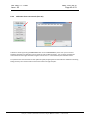
7.2.11 CT7 management
This screen allows to perform measurements, calibration and to introduce parameters into the CT7. This is
done through a graphic interface shown below.
When log checkbox is checked, the displayed data is saved to a log file .cvs .
The results are always appended to log file. No file is re-written.
Single and continuous measurements are logged in the same way.
Continuous measure allows endless measurements loop with Interval time between the measurements.
The check-boxes allows to show/hide columns of results. No data is lost, the fugures may be recalled at any
time.
See the next paragraphs for description of available functions.
Hint: You may copy data from screen to clipboard and paste them to Excel.
Note:
The measurements initiated from PC are not stored to internal CT7 memory.
They are not included into result archive file, but they may be logged to log file or copied to Excel from screen.
This document is OPO property. It may not be either used or copied without authorization.
OPO sprl, Crawhez 9, 4890 Thimister Clermont, Belgium. +32 87688989- +32 87598990
Ref :UM-CT7-11-001
Issue : 05
Date : 2015-06-15
Page 36 of 53
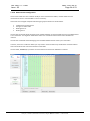
7.2.12 CT7 Management Parameters Table
The large table in the bottom part of the page contains all parameters crucial for CT7 precision.
In the NORMAL mode writing is disabled except of nominal values for reflection and diffusion targets used for
calibration. The two columns with darker background: Refl Target value and Dust Target value can be written
to flash memory of CT7 with buttons:
as explained in section 8.1 Soft Calibration Target values.
The others parameters are:
Parameter
Refl Calib Coeff
Refl T coef[%]
Refl Target value
Refl LED mod
Refl Ref PG
description
REFLECTION Channel
Calibration coefficient (calculated during calibration)
Thermal coefficient
Nominal value of the reference target (mirror) in % - user settable
% of LED current amplitude to be used for modulation
Analog Programmable Gain of the DSP processor for the reference channel
Refl Ref Att
Analog programmable attenuation of signal at DSP input for the reference channel
Refl Signal PG
Analog Programmable Gain of the DSP processor for the signal channel
Refl Signal Att
Analog programmable attenuation of signal at DSP input for the signal channel
Refl Repeat
Number of basic measurement blocks to use for the measure
Dust Channel
Calibration coefficient (calculated during calibration)
Thermal coefficient
Nominal value of the reference target (diffuser) in % - user settable
% of LED current amplitude to be used for modulation
Analog Programmable Gain of the DSP processor for the reference channel
Analog programmable attenuation of signal at DSP input for the reference channel
Analog Programmable Gain of the DSP processor for the signal channel
Analog programmable attenuation of signal at DSP input for the signal channel
Number of basic measurement blocks to use for the measure
Noise offset floor of the channel
Common
DC current (bias) for the LED ( Full amplitude in 254 steps)
Dust Calib Coef[%]
Dust T coef [%]
Dust Target value
Dust LED mod
Dust Ref PG
Dust Ref Att
Dust Signal PG
Dust Signal Att
Dust repeat
Dust Noise offset
LED DC
This document is OPO property. It may not be either used or copied without authorization.
OPO sprl, Crawhez 9, 4890 Thimister Clermont, Belgium. +32 87688989- +32 87598990
Ref :UM-CT7-11-001
Issue : 05
Date : 2015-06-15
Page 37 of 53
7.2.13 CT7 Management Function Buttons
7.2.13.1
Single meas.
When pressed, the measure defined by selected on MEAS MANAGEMENT panel cart is performed once.
7.2.13.2
Calibration
Perform calibration – see para. 8.2.3 Calibration from CT7-Console.
7.2.13.3
Status
This function retrieves internal voltage and software versions from CT7.
See para 8.3.3 Testing USB cable with CT7Console for discussion of voltages.
7.2.13.4
Export Params/Import Params
This pair of functions allow saving (export) and loading (import) all CT7 parameters. The configuration file
contains the data in a .ini style file and may be imported as a whole or only for selected parameters.
The file contains parameters and diagnostic information about CT7 and CT7-Console. Only parameters grouped
in blocks:
[CONSOLE]
[Channels]
[DSPchannels]
[DSPparams]
are uploaded.
Selective import of parameters is discussed in para. 8.1 Soft Calibration Target values .
It is important to remember that the parameter shall be preceded by his group header. CT7 Console will not start
to look after this parameter until the group header is read. Use as a model the sample config file in Annex 3 Configuration file (Export/Import)
7.2.13.5
Test CT7 Power
Performs test of CT7 power system and returns results with comments. This function is discussed in para.
8.3.38.3.3 Testing USB cable with CT7Console.
This document is OPO property. It may not be either used or copied without authorization.
OPO sprl, Crawhez 9, 4890 Thimister Clermont, Belgium. +32 87688989- +32 87598990
Ref :UM-CT7-11-001
Issue : 05
7.2.13.6
Date : 2015-06-15
Page 38 of 53
Read CT7
Reads all parameters from CT7 and display them on screen.
7.2.13.7
Write Mirror Target/Write Dust Target
You may manually edit columns of target coefficients for reflection and dust. These buttons write their
respective columns to CT7. Another way to change these parameters is a use of Import Params function – see
para. 8.1 Soft Calibration Target values.
7.2.13.8
Show last calibration
Recalls target sample parameters and the last calibration date stored in CT7 flash memory.
Note: Strictly speaking the target values are the ones actually in the memory, possibly the ones used to find the
calibrations coefficients have been overwritten. In case of doubt, check the target coefficients and re-calibrate.
7.2.13.9
Set CT7 To PC Clock
This function get time & date from PC clock and adjust CT7 real time clock to this value. Very useful when
changing the battery,
7.2.13.10
Start/Stop
Starts / stops the measurements defined by selected on MEAS MANAGEMENT panel cart is performed in a loop
with interval period.
7.2.13.11
Log
When checked, all the results appearing in the results grid are logged to a file in append mode.
7.2.13.12
Interval
Selection of interval of LOOP MEASURE. When START is pressed the measure defined by selected on MEAS
MANAGEMENT panel cart is performed each interval seconds/minutes.
7.2.13.13
DSP Update
Upload update of DSP firmware to CT7-Instrument. The uploaded file MUST be named CT7_DSP.bin.
The process lasts literally few second. A progress-bar shows the status. The user is guided by messages popingup at each step. The upload ends with restart of CT7, and automatic re-connection to PC.
In case of problems reset CT7 by pressing with a pen-tip the hidden RESET switch at the back, restart and
connect to PC normally.
HINT: We recommend exporting the parameters before updating DSP firmware.
This document is OPO property. It may not be either used or copied without authorization.
OPO sprl, Crawhez 9, 4890 Thimister Clermont, Belgium. +32 87688989- +32 87598990
Ref :UM-CT7-11-001
Issue : 05
Date : 2015-06-15
Page 39 of 53
7.2.14 Connecting to CT7
To use the PC-Link mode at CT7, you must:
Connect the CT7 with PC (USB cable)
Awake CT7, activate PC-link (para 6.4.1 PC Link) (With the left menu (LEFT) select SERVICE (DOWN - DOWN); then
select (RIGHT) and Enter the PC-Link function.)
Run the CT7 Console program on PC,
Especially for the first time connection, you should observe in the lower left corner of the PC screen the
case “connected/non-connected” shown as “connected”. If this is not the case, probably the timeout message will pop-up CONNECTION PROBLEM.
Press Ignore to acknowledge this message and push the button Communication Port Select.
A list of active COM ports appears. Most probably the CT7 port is the last one.
Select it and press ACCEPT button:
Than try again the connection to CT7 – press CT7 Connection button. If connection is established, at the left
bottom of the screen a message Connected to CT7 will appear. The COM port number is stored, and the next
time the connection will be transparent.
In case of persisting connection problem see troubleshooting.
This document is OPO property. It may not be either used or copied without authorization.
OPO sprl, Crawhez 9, 4890 Thimister Clermont, Belgium. +32 87688989- +32 87598990
Ref :UM-CT7-11-001
Issue : 05
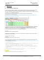
8
8.1
Date : 2015-06-15
Page 40 of 53
Maitenance
Soft Calibration Target values
CT7 has no intrinsic reflectivity reference. The construction of the instrument and measurement technique
ensures very high precision and stability of measured ratio of source intensity and returned signal.
This ratio is converted to reflectivity value by dividing it by calibration coefficient which is found by measuring
the known mirror in CALIBRATION operation.
For user convenience, a first surface AL mirror is provided as calibration reflectivity target.
(see also para 8.2.1 Calibration Target )
Note: At delivery CT7 will be loaded with parameters of provided reference mirror. This parameters may
slightly vary from values given in this manual.
The columns of Target values may be edited and uploaded to CT7 with Write Mirror Target and Write Dust
Target buttons respectively. After changing values you must perform CALIBRATION on your sample.
The change of target values may be performed with IMPORT Param. Function by importing your text file,
named for example MyTargetMirror.txt, including just following lines:
[Channels]
RTcoef={83.1;85.8;87.4;90.2;93.0;84.4;86.7}
The figures are the reflectivity values of Al mirrors respectively for wavelengths of 365nm, 404nm, 464nm,
522nm, 624nm, 760nm, 970nm.
Similar formula for dust target:
[Channels]
DTcoef ={10.0; 10.0; 10.0; 10.0; 10.0; 10.0; 10.0}
The CT7/Config folder contains file CT7_MirrorCoefficientsSample.txt. Importing this file will change only
calibration target reflectivity values. Simply replace our data by yours (yellow line), Import the file to CT7 and
perform Calibration on your sample.
;CT7 Parameters file
; This is a sample file allowing changing and keeping the reference of reflectivity
values used for calibration of CT7
; The list of channels is given as a reminder of wavelength sequence
; You may replace reflectivity values of RTcoef (OPO Al mirror) by your values.
; Importing this file to CT7 will change only one column in parameters table and
CT7 flash memory
; Note:
;1. The keywords: [Channels], RTcoef are obligatory, ";" is a comment sign
;2. You must use a DOT "." as decimal separator
;
[Channels]
;Channels={365nm;404nm;460nm;522nm;630nm;760nm;970nm}
RTcoef={82.6;83.1;85.2;89.9;90.5;83.8;89.5}
This document is OPO property. It may not be either used or copied without authorization.
OPO sprl, Crawhez 9, 4890 Thimister Clermont, Belgium. +32 87688989- +32 87598990
Ref :UM-CT7-11-001
Issue : 05
8.2
Date : 2015-06-15
Page 41 of 53
Calibration
CT7 returns reflectivity values based on ratio of emitted and received light multiplied by calibration coefficient
specific for each wavelength. The calibration process determines the scale for the measurements providing
known point on 0 to 100% linear characteristics of CT7 channels. After calibration CT7 will provide the results
according to this scale.
The measurement method, construction of the instrument and procesing algorithm were engineered in such
way that only optical path degradation (dust, scratches, ageing) may change the reading.
A calibration target mirror with reflectivity measured in our labs is provided as physical reference (note: even
this reference is subjected to ageing and degradations).
The instrument may be calibrated with provided reference mirror (see next paragraphe) or with your own,
known mirror. See chapter 8.1 Soft Calibration Target values to learn how to set CT7 to your laboratory
values.
8.2.1
Calibration Target
With the instrument a calibration mirror is provided.
The reference reflectivity values were measured with Strong’s WV setup.
channel
R365
uncertainty 0.2%
value
82.6%
R404
0.3%
83.1%
R460
0.1%
85.2%
R522
0.4%
89.9%
R630
0.2%
90.5%
R760
0.2%
83.8%
R970
0.5%
89.5%
Note: Optical references are not invariable. The reflection properties may change even if stored in good
conditions. Periodic validation of target properties with laboratory equipment is recommended.
8.2.2
Calibration from navigation switch (stand alone)
Usually calibration is performed when one suspects any pollution or if time elapsed since the last calibration is
estimated too long, or if some measured values are suspect.
Activate Menu MEASURE / Calibrate and place CT7 at the calibration target (there is 5 seconds delay).
Note: OPO has devised a VW jig allowing direct absolute calibration of a gauge just before using it. This is the
only procedure that allows checking the calibration of the instrument and correcting it if needed.
This document is OPO property. It may not be either used or copied without authorization.
OPO sprl, Crawhez 9, 4890 Thimister Clermont, Belgium. +32 87688989- +32 87598990
Ref :UM-CT7-11-001
Issue : 05
8.2.3
Date : 2015-06-15
Page 42 of 53
Calibration from CT7-Console (from PC)
Calibration starts by pressing CALIBRATION button on CT7-MANAGEMENT panel. Then you can choose
between calibrations of reflection (mirror target) or dust (scattering target). You are again prompted for
confirmation that the right calibration target is in front of CT7 – once confirmed, the calibration starts.
CT7 performs the measurement of ratio reference signal/ target signal and calculates the coefficients allowing
fitting arbitrary ratio measurement to the known values of target samples.
This document is OPO property. It may not be either used or copied without authorization.
OPO sprl, Crawhez 9, 4890 Thimister Clermont, Belgium. +32 87688989- +32 87598990
Ref :UM-CT7-11-001
Issue : 05
8.3
8.3.1
Date : 2015-06-15
Page 43 of 53
Battery
Battery Charge
CT7 uses two protected Li-Ion 3.7V 900mAh in format 14500 (~AA) cells connected in parallel as a source of
energy. Batteries Li Ion 800-1200mAh are also suitable but increasing their capacity will increase the charge
time above 4h.
Any USB socket of a PC is able to provide current up to 500mA. Hence, full charging of empty CT7 accumulators
may last up to 3-4 hours. The internal CT7 fuse (resettable) provides protection of the power source.
The state of charge can be checked thanks to STATUS function: V3 is the battery voltage. When V3=2.8V, the
batteries are empty, at 4.2V they are fully charged.
CT7 is charging only in OFF state. If connected to PC and operating the charger is disabled and CT7 powered
directly from USB socket. The current sourcing capacity of USB2 is too small to supply and charge in the same
time.
The state of the instrument is indicated by 3 LED on the top of the CT7:
Green: ON
Blue: Charge ended / Stand-by.
RED: Charge
CT7 in charge.
Note: that some USB cables are not suitable for supplying power. Exactly like for hard drives, a short, low
impedance connection is required. The internal monitoring of CT7 helps to verify supply quality. See 8.3.3
Testing USB cable with CT7Console)
8.3.2
External power source
Since 2012, the CT7 works with dual supply: battery or USB connector. If the 5V power is provided to USB
connector, CT7 does not need a battery to work.
In a laboratory use, operated from PC, batteries serve only to keep the clock running when CT7 is not
connected.
HINT: The monitoring of telescopes’ mirrors is not everyday task, it may happen that CT7 has discharged while
waiting for weeks for being used, and the technical time slot for monitoring is “just now” for only several
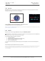
minutes. In such situation ANY device providing power to USB may be used as external power source for CT7:
a laptop, an external battery pack like Belkin Power Pack 2000.
Power Pack 2000 (Belkin)
Power Pack is not delivered with CT7 instrument.
This document is OPO property. It may not be either used or copied without authorization.
OPO sprl, Crawhez 9, 4890 Thimister Clermont, Belgium. +32 87688989- +32 87598990
Ref :UM-CT7-11-001
Issue : 05
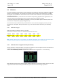
8.3.3
Date : 2015-06-15
Page 44 of 53
Testing USB cable with CT7Console
The battery and other internal voltages may be tested from Data-Management or CT7-Management panel by
pressing the button:
Power test reports for battery, “good” USB and “bad” USB cables.:
Battery operation
Good USB
Poor USB supply
(no USB power connection)
(Low impedance 60cm USB cable)
(High impedance 2m USB cable)
NOTE : Exaple of voltages and evaluation for NiMh batteries !!!
The poor USB cable generates alarms for more than one voltage. Brown voltage means “already not sufficient
supply but not yet blackout”.
Please note Charging state for battery evaluation in Good USB cable report.
8.3.4
Checking the USB cable with CT7
Thanks to internal monitoring of the CT7 we may measure the voltage drop over the USB cable.
It can be done with PC as in the previous paragraph, or from the CT7 menu. Go to menu FACTORY/STATUS,
observe V2 which is USB entry voltage:
Battery
Bad USB cable
Good USB cable
Depending on the cable (assuming with high probability that USB socket provides 5.0V) the entry voltage may
vary. For a “very good” cable we may observe 4.7-4.8 V.
The minimum acceptable value of V2 is 4.0V.
Status function gives slightly lower values than CT7Console evaluation in CT7 Power Test.
This document is OPO property. It may not be either used or copied without authorization.
OPO sprl, Crawhez 9, 4890 Thimister Clermont, Belgium. +32 87688989- +32 87598990
Ref :UM-CT7-11-001
Issue : 05
8.3.5
Date : 2015-06-15
Page 45 of 53
Quality of the power source
When connected to a power source, the battery state response shall contain the word USB Power or Full
Charge.
The state of the charger is indicated by LEDs on the top of CT7.
8.3.6
Changing the battery
Battery change sequence:
Unscrew the instrument bottom cover
Gently remove (let them drop-out) old batteries
Place new Protected Li-Ion 900mA (800-1200 cells.
Take care about polarity: Minus to spring contact.
Both Batteries are heading the same direction: “+” to cover
Gently introduce cover pins into the connector
Press the cover and place the screws
Replace the screws.
NOTE: Li-Ion batteries are placed heading BOTH “+” to the cover.
NOTE: We recommend changing the batteries every 2 years.
This document is OPO property. It may not be either used or copied without authorization.
OPO sprl, Crawhez 9, 4890 Thimister Clermont, Belgium. +32 87688989- +32 87598990
Ref :UM-CT7-11-001
Issue : 05
8.4
Date : 2015-06-15
Page 46 of 53
CT7 Firmware update
8.4.1
Procedure
The procedure is straightforward and takes just about 1 minute.
1.
2.
3.
4.
5.
6.
7.
Get new version of CT7_DSP.bin from support www (link) and place it in CT7\update folder
Connect CT7 to PC CT7-Console
At CT7-Console go to CT7 Management panel and click DSP update button
In a file-open dialog select the new firmware (*), press OPEN
Observe progress bar. A message “DSP upload success” pops-up : click OK
Finish upload with CR7 restart to activate the new firmware
a. A message informs you that CT7 will be switched off to activate uploaded version: click OK
b. CT7 is switched off, you have to power it up by pressing UP button of the CT7 navigation
switch. CT7 goes directly to PC-link mode. “UIF Locked” is displayed on CT7.
c. Now click OK on the PC CT7 Console message “Switch on CT7 and then press OK”
You may check the new version in the report generated by CT7 Management: ExportParams.
Function
(*) firmware must be named CT7_DSP.bin
This document is OPO property. It may not be either used or copied without authorization.
OPO sprl, Crawhez 9, 4890 Thimister Clermont, Belgium. +32 87688989- +32 87598990
Ref :UM-CT7-11-001
Issue : 05
Date : 2015-06-15
Page 47 of 53
8.4.2
Step by step firmware update procedure
Step
CT7 instrument
1
Get new version of firmware
PC-CT7 console
Download CT7.zip from support www (link), extract all to CT7 folder or
just extract CT&-DSP.bin and place it in CT7\update folder
2
Connect CT7 to PC CT7-Console
3
At CT7-Console go to CT7 Management panel and press DSP update button
Click button DSP update
4
In a file-open dialog select the new firmware; click OPEN
5
Observe progress bar. A message “DSP upload success” pops-up : click OK
Click OK
6
Finish upload with restart of CT7
CT7 is switched OFF by
PC-Console
Click OK.
This document is OPO property. It may not be either used or copied without authorization.
OPO sprl, Crawhez 9, 4890 Thimister Clermont, Belgium. +32 87688989- +32 87598990
Ref :UM-CT7-11-001
Issue : 05
Press UP buttom.
Date : 2015-06-15
Page 48 of 53
Wait for CT7 displaying “UIF Locked” and click OK
Done.
8.4.3
Firmware upload verification:
Select FACTORY / Version option from menu:
Verify DSP software version:
This document is OPO property. It may not be either used or copied without authorization.
OPO sprl, Crawhez 9, 4890 Thimister Clermont, Belgium. +32 87688989- +32 87598990
Ref :UM-CT7-11-001
Issue : 05
9
Date : 2015-06-15
Page 49 of 53
Delivrables
CT7 box contents:
4
1
3
2
1.
2.
3.
4.
CT7 (with batteries)
Cable USB
USB Flash memory (Install and documentation)(*)
calibration mirror (**)
(*) – Optional, latest downloads are available at support page (see para. 14 Annex 4 - Support ) the
“soft” delivery helps us to provide the user always with the latest version of documentation and PC
application
(**)- Optional
10 Abréviations
Cart
FWHM
TBC
TBD
USB
- The name given for selection of wavelengths used for a measurement
- Full Width Half Maximum
- To Be Confirmed
- To Be Defined
- Universal Serial Bus
This document is OPO property. It may not be either used or copied without authorization.
OPO sprl, Crawhez 9, 4890 Thimister Clermont, Belgium. +32 87688989- +32 87598990
Ref :UM-CT7-11-001
Issue : 05
Date : 2015-06-15
Page 50 of 53
11 Annex 1 - CT7 Charateristisc
CT7 Accuracy
Accuracy of reflectivity is given for reflectivity>50%
Wavelength
365
405
464
522
624
760
970
Bandpass
10
0.2%
15
0.2%
25
0.2%
30
0.2%
30
0.2%
40
0.2%
50
0.5%
0.01%
0.01%
0.01%
0.01%
0.01%
0.01%
0.03%
Absolute accuracy*
Repeatability**
* Absolute accuracy obtained using the VW jig for calibrating the gauge.
** for a single measurement
Value
See table above
± 0.05%/°C
6
7
Parameter
Repeatability
Thermal Stability
Incidence angle
Reflection wavelengths
Scattering (DUST) index
wavelengths
Detectors
Operating temperature
8
9
Storage temperature
Power consumption
10
Battery
-20°C +60°C
5V, Current limited to 500mA
500 -350mA when in charge
450mA when ON
2x 14500 LiIon 800mAh 3.7V
11
Charge
About 3.5h
12
Battery practical
capacity
Power/data connector
Dimensions
Mass
Minimum 75 measures Reflection, 3 days in
stand-by
Mini USB, type B
73 x 85 x 147 mm
700g
1
2
3
4
5
13
14
15
Comments
Short term (5 min)
% full range
8°
365nm, 404nm, 464nm, 522nm, 624nm, 760nm, 970nm
Same as reflection
UV Enhanced Silicon Photodiodes
-15 .. +40 °C
Sources are LED
Sources are LED
Note : CT7 may need
recalibration at actual
temperature
Batteries may show
reduction of capacity at
low temperatures.
Not operating.
Limited by construction.
Protected by resettable
fuse
800-1200 mAh are also
suitable
From USB socket, CT7
switched OFF
Fully charged, new battery
This document is OPO property. It may not be either used or copied without authorization.
OPO sprl, Crawhez 9, 4890 Thimister Clermont, Belgium. +32 87688989- +32 87598990
Ref :UM-CT7-11-001
Issue : 05
Date : 2015-06-15
Page 51 of 53
12 Annex 2 - Troubleshooting
Problem
POWER:
CT7 does not power–up
Most probable Cause
Battery discharged
2
POWER:
CT7 switch off during operation
Battery discharged
3
CONNECTION:
CT-7 Console does not connect in
automatic way to the connected
instrument
Virtual COM port number has
changed
4
CONNECTION:
CT-7 Console does not connect in
automatic way to the connected
instrument, interface seems to be
frozen
CT-7 is in “false UIF” mode – the
processors of the OLED Display
and DSP are desynchronized
5
BATTERY CHARGE
After long charge from PC (CT7 is
OFF), the battery discharge rapidly
1.Wrong USB cable. The serial
resistance is too high, producing
significant voltage drop over the
cable.
2. Damaged battery
6
Results are NaN, +inf.
Division by 0 in processing. The
codec (ADC) of the DSP has been
set to incorrect configuration and
returns 0.
7
Low Battery
CT7 emits a series of beeps and
shuts down
Low battery . CT7 protects the
battery against excessive discharge
and disconnects the battery
1
Solution / notes
connect to USB power, CT7 should
start once powered, Check STATUS
V3 (Vbat). V3 shall be above 3.0V to
power up.
CT7 may operate on USB power
without batteries.
Charge the battery with USB, try to
see Status voltage V3. V3 shall be
above 3.0V to power up.
CT-7 instrument dialogues with PC
using a virtual COM port. CT-7
console stores the last used port and
tries to connect using the same the
next time CT7 is connected.
Open SELECT PORT option and
REFRESH list of ports. Try to Select
the last port at the first try (most
probably this is CT7 port), if co
connection is obtained than follow
with others
RESET CT7, go to PC-link mode again.
OBSERVE: at CT7_Console SELECTPORT a list of COM ports before and
after connecting CT7 USB cable (do
not forget to refresh the list) – a new
port shall appear.
Use USB cable suitable for high
current devices, like hard drive.
These cables are relatively short and
thick.
1. Observe V2 at STATUS – this is
USB socket voltage, if is less
than 4.2V the CT7 will not
charge the battery
2. Check BATTERY – if only
percentage “x%” is displayed the
charger will not operate with
this cable. You shall see: “ x%
USB Pwr”
Import last known good
configuration file (or the sample
one).
Use CT7-Console/CT7 Management
panel/Import Parameters
Connect USB power to continue work
with CT7.
Leave CT7 connected (and OFF) until
the BLUE led lights-up indicating full
battery charge.
This document is OPO property. It may not be either used or copied without authorization.
OPO sprl, Crawhez 9, 4890 Thimister Clermont, Belgium. +32 87688989- +32 87598990
Ref :UM-CT7-11-001
Issue : 05
Date : 2015-06-15
Page 52 of 53
13 Annex 3 - Configuration file (Export/Import)
The example of configuration file generated by Export Parameters function:
;CT7 Parameters file
file_ver=1.3.00
file_date=10-07-2014 19:05
[CT7Console]
ConsoleSerial=ver 1.3.05
ConsoleBuiltDate=Built 2014-07-09
[CT7version]
serial=99000001
DSPversion=DSP v. 1.3.06
DSPBuiltDate= built 2014-06-05
OLEDversion=1.2.11
OLEDBuiltDate=2014-05-16
OLEDGversion=NA
[CONSOLE]
LED_DC=160
LEDcurrent=0.8
RrefTarget=56000
RsigTarget=48000
RPGALimit=36
RLEDLimit=0.85
DrefTarget=56000
DsigTarget=35000
DPGALimit=36
DLEDLimit=0.85
[Channels]
Channels={365nm;404nm;460nm;522nm;630nm;760nm;970nm}
Rcal={1.0202;1.0281;1.0549;1.0599;1.0532;1.0112;1.0247}
TRcal={0.04995;0.00883;0.01103;0.01233;0.01968;0.02404;0.06927}
RTcoef={82.6;83.1;85.2;89.9;90.5;83.8;89.5}
RModul={1;1;1;1;1;0.8;1}
RMCount={1;1;1;1;1;1;1}
Dcal={1;1;1;1;1;1;1}
TDcal={0;0;0;0;0;0;0}
DTCoef={10;10;10;10;10;10;10}
DModul={1;1;1;1;1;0.8;1}
DNOparam={0;0;0;0;0;0;0}
DMCount={1;1;1;1;1;1;1}
[DSPchannels]
GRRcoef={26;28;36;36;35;27;30}
GRScoef={0;3;12;9;7;0;10}
GDRcoef={26;28;36;36;35;27;30}
GDScoef={0;3;12;9;7;0;10}
IRRcoef={1;1;1;1;1;1;1}
IRScoef={1;1;1;1;1;1;1}
IDRcoef={1;1;1;1;1;1;1}
IDScoef={1;1;1;1;1;1;1}
LEDdc={180;160;180;180;160;180;200}
[DSPparams]
DSPFilter=1
DSPFinePhaseR=0
DSPDSPCoarseDelayR_R=0
DSPCoarseDelayR_S=0
DSPFinePhaseD=0
DSPCoarseDelayD_R=0
DSPCoarseDelayD_S=10
[status]
Vbat=2.77
Tbat=25.6
TDet=25.6
TLED=27.5
VxADC={8.63;3.3;4.72;2.95;4.96;5;3.36;4.33}
CT7Index=0
CT7time=20-07-2014 19:05
LastRcalib=09-07-2014 11 h
LastDcalib=09-07-2014 14 h
LastRCalibT=21.3 CLastDCalibT=22.2 C
[CT7Registers]
ConsoleVer=ver 1.3.05
CT7Folder=D:\Documents\CT7_MyCT7
ResultsFolder=D:\Documents\CT7_MyCT7\Results
ConfigFolder=D:\Documents\EASY_AUTO\projects\P091017_CT7\4_EL\Modif2014\
UpdateFolder=D:\Documents\workspace\CT7_DSP_10\bin
DocFolder=D:\Documents\CT7_MyCT7\Documents
ExportFolder=D:\Documents\CT7_MyCT7\Export
HelpFile=D:\Documents\CT7_MyCT7\Documents\umCT711001i02_user manual.pdf
UpdateDSPFile=D:\Documents\workspace\CT7_DSP_10\bin\CT7_DSP.bin
UpdateOLEDFile=NA
ExportFile=D:\Documents\CT7_MyCT7\Export\CT7DATAwitherror.CSV
MeasureFile=D:\Documents\CT7_MyCT7\Results\Archive0Archive0012000.Meas
MeasureConfigFile=D:\Documents\CT7\Config\Sample_CT7_LABO.MeasCfg
LogFile=D:\Documents\CT7_MyCT7\Results\CT7_9902-TEST7.csv
SupportWWW=http://www.a1pixel.pl/CT7/index.html
ComPort=COM27
This document is OPO property. It may not be either used or copied without authorization.
OPO sprl, Crawhez 9, 4890 Thimister Clermont, Belgium. +32 87688989- +32 87598990
Ref :UM-CT7-11-001
Issue : 05
Date : 2015-06-15
Page 53 of 53
14 Annex 4 - Support
Additional information:
CT7 Presentation
Actual version
Firmware update (download)
CT7 Console update (download)
User Manual (download)
Technical notes
may be found at www.a1pixel.pl/CT7/index.html in CT7 user area.
For any issue not covered by this document you may contact:
Daniel Malaise
OPO sprl
[email protected]
www.opo.be
In particular OPO covers the following topics:
general concept, system, optical design, mechanical design, processing.
Pawel Woszczyk
A1Pixel ltd
[email protected]
www.a1pixel.pl/CT7/index.html
In particularA1Pixel covers the following topics:
system, electronics and software design, over-all operation scenario, software flow, updates, repair.
This document is OPO property. It may not be either used or copied without authorization.
OPO sprl, Crawhez 9, 4890 Thimister Clermont, Belgium. +32 87688989- +32 87598990