1
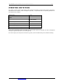
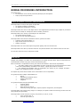
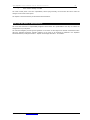
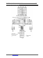
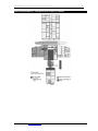
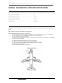
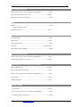
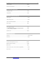
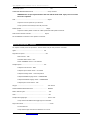
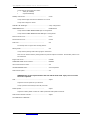
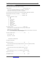
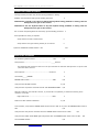
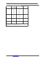
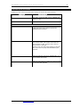
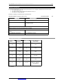
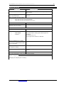
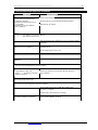
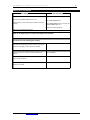
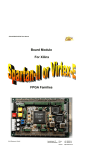
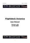
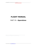
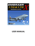
‘737 Captain’ FLIGHT MANUAL Part III –Normal Procedures
DO NOT USE FOR FLIGHT
FLIGHT MANUAL
PART III - Normal Procedures
Captain Sim is not affiliated with any entity mentioned or pictured in this document.
All trademarks are the property of their respective owners.
© 2012 Captain Sim www.captainsim.com
1
‘737 Captain’ FLIGHT MANUAL Part III –Normal Procedures
DO NOT USE FOR FLIGHT
2
ABOUT THIS MANUAL
VERSION: 04 MAY, 2012
WARNING: THIS MANUAL IS DESIGNED FOR MICROSOFT® FSX USE ONLY. DO NOT USE FOR FLIGHT.
The ‘737 Captain’ FLIGHT MANUAL is organized into four Parts:
Each Part is provided as a separate Acrobat® PDF document:
Click START > Programs > Captain Sim > 737 Captain >
•
Part I – User’s Manual
o The User’s Manual describes the ‘737 Captain’ Sim product as a software title.
•
Part II – Aircraft Systems
•
Part III – Normal Procedures - this document
•
Part IV – Flight Crew Training Manual
Adobe Acrobat® Reader Required
FOR GENERAL INFORMATION ON THE ‘737 CAPTAIN’ PRODUCT PLEASE USE WWW.CAPTAINSIM.COM .
THIS MANUAL PROVIDES ADDITIONAL INFORMATION ONLY, WHICH IS NOT AVAILABLE ON THE WEB SITE.
© 2012 Captain Sim www.captainsim.com
‘737 Captain’ FLIGHT MANUAL Part III –Normal Procedures
DO NOT USE FOR FLIGHT
737 Captain FLIGHT MANUAL
PART III - CONTENTS
3
OPERATING LIMITATIONS
5
5
5
5
6
6
6
7
7
7
7
WEIGHT LIMITATIONS 737-200 AIRPLANES
AIR SYSTEMS
ANTI-ICE, RAIN
AUTOPILOT
ELECTRICAL POWER
ENGINES
APU
FLIGHT CONTROLS
FLIGHT MANAGEMENT, NAVIGATION
FUEL
LANDING GEAR
8
NORMAL PROCEDURES: INTRODUCTION
8
8
9
10
11
12
NORMAL PROCEDURES PHILOSOPHY AND ASSUMPTIONS
CREW DUTIES
SCAN FLOW AND AREAS OF RESPONSIBILITY
PREFLIGHT AND POSTFLIGHT SCAN FLOW
AREAS OF RESPONSIBILITY - CAPTAIN AS PILOT FLYING OR TAXIING
AREAS OF RESPONSIBILITY - FIRST OFFICER AS PILOT FLYING OR TAXIING
13
NORMAL PROCEDURES: AMPLIFIED PROCEDURES
13
13
17
22
24
26
26
27
28
30
31
32
33
33
34
35
36
37
38
39
PRELIMINARY PREFLIGHT PROCEDURE - CAPTAIN OR FIRST OFFICER
EXTERIOR INSPECTION
PREFLIGHT PROCEDURE - FIRST OFFICER
PREFLIGHT PROCEDURE - CAPTAIN
BEFORE START PROCEDURE
PUSHBACK OR TOWING PROCEDURE
ENGINE START PROCEDURE
BEFORE TAXI PROCEDURE
BEFORE TAKEOFF PROCEDURE
TAKEOFF FLAP RETRACTION SPEED SCHEDULE
CLIMB AND CRUISE PROCEDURE
DESCENT PROCEDURE
APPROACH PROCEDURE
FLAP EXTENSION SCHEDULE
LANDING PROCEDURE
GO-AROUND AND MISSED APPROACH PROCEDURE
LANDING ROLL PROCEDURE
AFTER LANDING PROCEDURE
SHUTDOWN PROCEDURE
SECURE PROCEDURE
40
CUSTOMER CARE
40
SPECIAL THANKS TO
© 2012 Captain Sim www.captainsim.com
3
‘737 Captain’ FLIGHT MANUAL Part III –Normal Procedures
DO NOT USE FOR FLIGHT
4
OPERATING LIMITATIONS
This chapter contains Airplane Flight Manual (AFM) limitations and Boeing recommended operating information.
Limitations that are obvious, shown on displays or placards, or incorporated within an operating procedure are
not contained in this chapter.
Runway slope
+/- 2%
Maximum Takeoff and Landing Tailwind Component
Maximum speeds
15 knots
Turbulent airspeed
280 KIAS/.70M
Mach trim inoperative
max speed .74M
Maximum Operating Altitude
37,000 feet
Maximum Takeoff and Landing Altitude
8,300 feet
Observe Vmo pointer
gear/ flap placards
and
Verify that an operational check of the flight deck door access system (as installed) has been accomplished
according to approved procedures once each flight day.
On revenue flights, the escape slide retention bar (girt bar) must be installed during taxi, takeoff and landing.
© 2012 Captain Sim www.captainsim.com
‘737 Captain’ FLIGHT MANUAL Part III –Normal Procedures
DO NOT USE FOR FLIGHT
5
WEIGHT LIMITATIONS 737-200 AIRPLANES
CHARACTERISTICS
737-200
TAKEOFF WEIGHT, POUNDS
737-100
737-200ADV
737-200C/F
116,000
111,000
128,100
116,000
ZERO FUEL WEIGHT, POUNDS
95,000
90,000
95,000
95,000
OPERATING EMPTY WEIGHT, POUNDS
59,800
62,000
65,700
65,700
AIR SYSTEMS
The maximum cabin differential pressure (relief valves) is 8.65 psi.
ANTI-ICE, RAIN
Engine TAI must be on when icing conditions exist or are anticipated, except during climb and cruise below
-40°C SAT.
Minimum N1 RPM for operating in icing conditions except for landing: 40% when TAT between 0° and 10°C;
55% when TAT below 0°C; 70% in moderate to severe icing conditions when TAT below -6.5°C.
Window heat inop: max speed 250 KIAS below 10,000 ft.
AUTOPILOT
Use of autopilot not authorized for takeoff or landing.
Do not use autopilot roll channel above 30,000 feet with yaw damper inoperative.
Do not use autopilot pitch channel above .81M with hydraulic system A or B depressurized.
ELECTRICAL POWER
Max engine driven generator load: 111 amps.
Maximum generator drive oil temperature: 157° C
© 2012 Captain Sim www.captainsim.com
‘737 Captain’ FLIGHT MANUAL Part III –Normal Procedures
DO NOT USE FOR FLIGHT
6
ENGINES
ENGINE LIMIT DISPLAY MARKINGS
Maximum and minimum limits are red. Caution limits are amber.
GENERAL ENGINE LIMITATIONS
Maximum N1 RPM
100.1%
Maximum N2 RPM
100 %
Maximum Acceleration EGT (2 minutes)
580° C
Maximum Takeoff EGT (5 minutes)
580° C
Maximum Continuous EGT
540° C
Maximum Start EGT
Ambient Temperature above 15°C (momentary)
Ambient Temperature below 15°C
Maximum Oil Temperature (continuous)
(15 minutes)
420° C
350° C
120° C
121° C
157° C
OIL PRESSURE
Maximum Oil Pressure
55 psi
Minimum Oil Pressure
40 psi
ENGINE IGNITION
Engine ignition must be on during takeoff and landing.
REVERSE THRUST
Intentional selection of reverse thrust in flight is prohibited.
APU
Maximum start EGT is 760° C. Maximum continuous EGT is 710° C.
With APU bleed + electrical load, maximum altitude is 10,000 ft. With APU bleed, maximum altitude is 17,000
ft.
With APU electrical load, maximum altitude is 35,000 ft. APU bleed valve must be closed when:
•
ground air connected and isolation valve open
•
engine no. 1 bleed valve open
•
isolation valve and engine no. 2 bleed valve open.
APU bleed valve may be open during engine start, but avoid engine power above idle.
© 2012 Captain Sim www.captainsim.com
‘737 Captain’ FLIGHT MANUAL Part III –Normal Procedures
DO NOT USE FOR FLIGHT
7
FLIGHT CONTROLS
Flap extension altitude is 20,000 ft.
In flight, do not extend the SPEED BRAKE lever beyond the FLIGHT DETENT.
Avoid rapid and large alternating control inputs, especially in combination with large changes in pitch, roll, or
yaw (e.g. large side slip angles) as they may result in structural failure at any speed, including below VA.
FLIGHT MANAGEMENT, NAVIGATION
Do not operate the weather radar in a hangar or within 50 feet of fueling operations or fuel spills.
Do not operate the weather radar within 160 feet of personnel. Warm up radar in STBY position only.
FUEL
Do not reset a tripped fuel pump circuit breaker. Maximum fuel temperature is 49° C.
Minimum fuel temperature is fuel freeze point +3° C or -45° C, whichever is higher.
FUEL LOADING
On the ground, main tanks 1 and 2 must be full if center tank contains more than 1000 lbs.
LANDING GEAR
Do not apply brakes until after touchdown.
© 2012 Captain Sim www.captainsim.com
‘737 Captain’ FLIGHT MANUAL Part III –Normal Procedures
DO NOT USE FOR FLIGHT
8
NORMAL PROCEDURES: INTRODUCTION
This chapter gives:
•
an introduction to the normal procedures philosophy and assumptions
•
step by step normal procedures
NORMAL PROCEDURES PHILOSOPHY AND ASSUMPTIONS
Normal procedures verify for each phase of flight that:
•
the airplane condition is satisfactory
•
the flight deck configuration is correct
Normal procedures are done on each flight. Refer to the Supplementary Procedures (SP) chapter for procedures
that are done as needed, for example the adverse weather procedures.
Normal procedures are used by a trained flight crew and assume:
•
all systems operate normally
•
the full use of all automated features.
Normal
•
•
•
procedures also assume coordination with the ground crew before:
hydraulic system pressurization, or
flight control surface movement, or
airplane movement
Normal procedures do not include steps for flight deck lighting and crew comfort items.
Normal procedures are done by recall and scan flow. The panel illustration in this section shows the scan flow.
The scan flow sequence may be changed as needed.
CREW DUTIES
Preflight and postflight crew duties are divided between the captain and first officer. Phase of flight duties are
divided between the Pilot Flying (PF) and the Pilot Monitoring (PM.)
Each crewmember is responsible for moving the controls and switches in their area of responsibility:
•
The phase of flight areas of responsibility for both normal and non-normal procedures are shown
in the Area of Responsibility illustrations in this section. Typical panel locations are shown.
•
The preflight and postflight areas of responsibility are defined by the "Preflight Procedure Captain" and "Preflight Procedure - First Officer".
The captain may direct actions outside of the crewmember's area of responsibility.
The general PF phase of flight responsibilities are:
•
taxiing
•
flight path and airspeed control
•
airplane configuration
•
navigation
The general PM phase of flight responsibilities are:
•
checklist reading
•
communications
•
tasks asked for by the PF
•
monitoring taxiing, flight path, airspeed, airplane configuration, and navigation
PF and PM duties may change during a flight. For example, the captain could be the PF during taxi but be the PM
during takeoff through landing.
Normal procedures show who does a step by crew position (C, F/O, PF, or PM):
•
in the procedure title, or
•
in the far right column, or
© 2012 Captain Sim www.captainsim.com
‘737 Captain’ FLIGHT MANUAL Part III –Normal Procedures
DO NOT USE FOR FLIGHT
•
in the column heading of a table
9
The mode control panel is the PF's responsibility. When flying manually, the PF directs the PM to make the
changes on the mode control panel.
The captain is the final authority for all tasks directed and done.
SCAN FLOW AND AREAS OF RESPONSIBILITY
The scan flow and areas of responsibility diagrams shown below are representative and may not match the
configuration of your airplane.
The scan flow diagram provides general guidance on the order of each flight crew member should follow when
doing the preflight procedures. Specific guidance on the items to be checked are detailed in the amplified
Normal Procedures, Preflight Procedure - Captain and Preflight Procedure - First Officer.
© 2012 Captain Sim www.captainsim.com
‘737 Captain’ FLIGHT MANUAL Part III –Normal Procedures
DO NOT USE FOR FLIGHT
PREFLIGHT AND POSTFLIGHT SCAN FLOW
© 2012 Captain Sim www.captainsim.com
10
‘737 Captain’ FLIGHT MANUAL Part III –Normal Procedures
DO NOT USE FOR FLIGHT
AREAS OF RESPONSIBILITY - CAPTAIN AS PILOT FLYING OR TAXIING
© 2012 Captain Sim www.captainsim.com
11
‘737 Captain’ FLIGHT MANUAL Part III –Normal Procedures
DO NOT USE FOR FLIGHT
AREAS OF RESPONSIBILITY - FIRST OFFICER AS PILOT FLYING OR TAXIING
© 2012 Captain Sim www.captainsim.com
12
‘737 Captain’ FLIGHT MANUAL Part III –Normal Procedures
DO NOT USE FOR FLIGHT
13
NORMAL PROCEDURES: AMPLIFIED PROCEDURES
PRELIMINARY PREFLIGHT PROCEDURE - CAPTAIN OR FIRST OFFICER
The Preliminary Preflight Procedure assumes that the Electrical Power Up supplementary procedure is complete.
Electronic master switches ……………………………………………………… ON
Circuit breakers (P6 panel) …………………………………………………….. Check
Circuit breakers (P18 panel)…………………………………………………… Check
Parking brake …………………………………………………………………………. As needed
EXTERIOR INSPECTION
Before each flight the captain, first officer, or maintenance crew must verify that the airplane is satisfactory for
flight.
Items at each location may be checked in any sequence.
Use the
•
•
•
•
•
•
•
•
•
detailed inspection route below to check that:
the surfaces and structures are clear, not damaged, not missing parts and there are no fluid leaks
the tires are not too worn, not damaged, and there is no tread separation
the gear struts are not fully compressed
the engine inlets and tailpipes are clear, the access panels are secured, the exterior is not damaged,
and the reversers are stowed
the
the
the
the
the
doors and access panels that are not in use are latched
probes, vents, and static ports are clear and not damaged
skin area adjacent to the pitot probes and static ports is not wrinkled
antennas are not damaged
light lenses are clean and not damaged
INSPECTION ROUTE
© 2012 Captain Sim www.captainsim.com
‘737 Captain’ FLIGHT MANUAL Part III –Normal Procedures
DO NOT USE FOR FLIGHT
LEFT FORWARD FUSELAGE
Probes, sensors, ports, vents, and drains (as applicable)......................Check
Doors and access panels (not in use)............................................Latched
Main deck cargo door (as installed)....................................................Check
NOSE
Radome.........................................................................................Check
Conductor straps - Secure
Forward E and E door...................................................................Secure
NOSE WHEEL WELL
Tires and wheels.............................................................................Check
Exterior light................................................................................Check
Gear strut and doors........................................................................Check
View port.......................................................................Clear and clean
Nose wheel steering assembly...........................................................Check
RIGHT FORWARD FUSELAGE
Probes, sensors, ports, vents, and drains (as applicable)....................Check
Doors and access panels (not in use)............................................Latched
RIGHT WING ROOT, PACK, AND LOWER FUSELAGE
Ram air deflector door...............................................................Extended
Pack and pneumatic access doors...................................................Secure
Probes, sensors, ports, vents, and drains (as applicable)......................Check
Exterior lights...............................................................................Check
Leading edge flaps........................................................................Check
NUMBER 2 ENGINE
Access panels...........................................................................Latched
Probes, sensors, ports, vents, and drains (as applicable)....................Check
Fan blades, probes, and spinner.....................................................Check
© 2012 Captain Sim www.captainsim.com
14
‘737 Captain’ FLIGHT MANUAL Part III –Normal Procedures
DO NOT USE FOR FLIGHT
Thrust reversers........................................................................Stowed
Exhaust area and tailcone..............................................................Check
RIGHT WING AND LEADING EDGE
Leading edge slats......................................................................Check
Wing Surfaces............................................................................Check
RIGHT WING TIP AND TRAILING EDGE
Position lights...............................................................................Check
Static discharge wicks...................................................................Check
Aileron and trailing edge flaps......................................................Check
Exterior lights …………………………………………………………………………………
Check
RIGHT MAIN GEAR
Tires, brakes and wheels..............................................................Check
Verify that the wheel chocks are in place as needed.
Gear strut, actuators, and doors...................................................Check
Hydraulic lines...........................................................................Secure
RIGHT MAIN WHEEL WELL
View port.....................................................................………………. Clear and clean
Wheel well....................................................................................Check
RIGHT AFT FUSELAGE
Doors and access panels (not in use)..........................................Latched
Negative pressure relief door.......................................................Closed
Outflow valve……………………………………………………………………………………..
Check
Probes, sensors, ports, vents, and drains (as applicable)....................Check
APU air inlet..................................................................................Open
© 2012 Captain Sim www.captainsim.com
15
‘737 Captain’ FLIGHT MANUAL Part III –Normal Procedures
DO NOT USE FOR FLIGHT
TAIL
Vertical stabilizer and rudder........................................................Check
Elevator feel probes....................................................................Check
Horizontal stabilizer and elevator..................................................Check
Static discharge wicks.................................................................Check
APU exhaust outlet.....................................................................Check
Verify that there is no indication of scorch marks on the outlet.
LEFT AFT FUSELAGE
Doors and access panels (not in use)..........................................Latched
Probes, sensors, ports, vents, and drains (as applicable).................Check
LEFT MAIN WHEEL WELL
View port......................................................................Clear and clean
Wheel well.................................................................................Check
LEFT MAIN GEAR
Tires, brakes and wheels.............................................................Check
Verify that the wheel chocks are in place as needed.
Gear strut, actuators and doors....................................................Check
Hydraulic lines...........................................................................Secure
LEFT WING TIP AND TRAILING EDGE
Aileron and trailing edge flaps........................................................Check
Static discharge wicks...................................................................Check
Position lights...............................................................................Check
Exterior lights...............................................................................Check
© 2012 Captain Sim www.captainsim.com
16
‘737 Captain’ FLIGHT MANUAL Part III –Normal Procedures
DO NOT USE FOR FLIGHT
LEFT WING AND LEADING EDGE
Wing Surfaces..............................................................................Check
Leading edge slats........................................................................Check
NUMBER 1 ENGINE
Exhaust area and tailcone..............................................................Check
Thrust reversers.......................................................................Stowed
Fan blades, probes, and spinner.....................................................Check
Probes, sensors, ports, vents, and drains (as applicable)....................Check
Access panels..........................................................................Latched
LEFT WING ROOT, PACK, AND LOWER FUSELAGE
Leading edge flaps…………………………………………………………………….
Check
Probes, sensors, ports, vents, and drains (as applicable)....................Check
Exterior lights...............................................................................Check
PREFLIGHT PROCEDURE - FIRST OFFICER
The first officer normally does this procedure. The captain may do this procedure if needed.
Flight control panel ……………………………………………………………………. Check
FLIGHT CONTROL switches - Guards closed
Flight SPOILER switches - Guards closed
YAW DAMPER switch - ON
NAV transfer switches...........................................................NORMAL
Verify that the FUEL VALVE CLOSED lights are illuminated dim.
Verify that the FILTER ICING lights are extinguished.
Fuel HEAT switches – OFF
Verify that the VALVE OPEN lights are extinguished.
CROSSFEED selector – CLOSED
Verify that the VALVE OPEN light is extinguished.
FUEL PUMP switches – OFF
Verify that the center tank fuel pump LOW PRESSURE lights are extinguished.
© 2012 Captain Sim www.captainsim.com
17
‘737 Captain’ FLIGHT MANUAL Part III –Normal Procedures
DO NOT USE FOR FLIGHT
18
Verify that the auxiliary tank fuel pump LOW PRESSURE lights (as installed) are extinguished.
Verify that the main tank fuel pump LOW PRESSURE lights are illuminated.
Electrical panel................................................................................Set
BATTERY switch - Guard closed
GALLEY power switch - ON
STANDBY POWER switch - Guard closed
Verify that the STANDBY PWR OFF light is extinguished.
Generator drive DISCONNECT switches - Guards closed
Verify that the LOW OIL PRESSURE lights are illuminated.
Verify that the HIGH OIL TEMP lights are extinguished.
DRIVE TEMPERATURE switch - As needed
BUS TRANSFER switch - Guard closed
Verify that the TRANSFER BUS OFF lights are extinguished.
Verify that the BUS OFF lights are extinguished.
Verify that the GEN OFF BUS lights are illuminated.
Overheat and fire protection panel (Passenger airplanes)
APU switch (as needed).............................................................START
When the APU GEN OFF BUS light is illuminated:
APU GENERATOR bus switches – ON
Verify that the BUS OFF lights are extinguished.
Verify that the TRANSFER BUS OFF lights are extinguished.
Verify that the LOW OIL QUANTITY light is extinguished.
Verify that the APU LOW OIL PRESSURE light is extinguished.
Verify that the APU HIGH OIL TEMP light is extinguished.
Verify that the APU OVERSPEED light is extinguished.
EQUIPMENT COOLING switch.................................................NORMAL
Verify that the OFF light is extinguished.
EMERGENCY EXIT LIGHTS switch...........................................Guard closed
Verify that the NOT ARMED light is extinguished.
Passenger signs...................................................................Set
NO SMOKING switch - AUTO or ON
© 2012 Captain Sim www.captainsim.com
Check
‘737 Captain’ FLIGHT MANUAL Part III –Normal Procedures
DO NOT USE FOR FLIGHT
FASTEN BELTS switch - AUTO or ON
Windshield WIPER selector....................................................OFF
If the windshield wipers are not stowed, place the selector to PARK then OFF.
WINDOW HEAT switches.......................................................ON
Position the switches ON at least 10 minutes before takeoff.
Verify that the OVERHEAT lights are extinguished.
Verify that the ON lights are illuminated except at high ambient temperatures.
PITOT STATIC HEAT switches................................................OFF
Verify that all PROBE HEATER lights are illuminated.
WING ANTI-ICE switch.........................................................OFF
Verify that the VALVE OPEN lights are extinguished.
ENGINE ANTI-ICE switches....................................................OFF
Verify that the VALVE OPEN lights are extinguished.
Hydraulic panel.............................................................Set
GROUND INTERCONNECT switch - CLOSE
HYDRAULIC PUMPS switches - ON
Verify that the LOW PRESSURE lights are illuminated.
ELECTRIC HYDRAULIC PUMPS switches - OFF
Verify that the OVERHEAT lights are extinguished.
Verify that the LOW PRESSURE lights are illuminated.
Cabin altitude panel .............................................................Set
SMOKE CLEARANCE switch - Guard closed
Air conditioning panel ...........................................................Set
AIR TEMPERATURE source selector - As needed
Verify that the DUCT OVERHEAT lights are extinguished.
Temperature selectors - As needed
Verify that the RAM DOOR FULL OPEN lights are illuminated.
GASPER FAN switch - As needed
Air conditioning PACK switches - Set
One switch - ON
Other switch - OFF
ISOLATION VALVE switch - AUTO
Engine BLEED air switches - ON
APU BLEED air switch - ON
Verify that the DUAL BLEED light is illuminated.
© 2012 Captain Sim www.captainsim.com
19
‘737 Captain’ FLIGHT MANUAL Part III –Normal Procedures
DO NOT USE FOR FLIGHT
20
Verify that the PACK TRIP OFF lights are extinguished.
Verify that the WING-BODY OVERHEAT lights are extinguished.
Verify that the BLEED TRIP OFF lights are extinguished.
Cabin pressurization panel ....................................................Set
Verify that the AUTO FAIL light is extinguished.
Verify that the OFF SCHED DESCENT light is extinguished.
FAILURE ALTITUDE indicator - Cruise altitude
LANDING ALTITUDE indicator - Destination field elevation
CABIN RATE selector – Index
CABIN ALTITUDE indicator - 200 feet below destination field elevation
FLIGHT/GROUND switch - GRD Pressurization mode selector – AUTO
Verify that the STANDBY light is extinguished. Verify that the MANUAL light is extinguished.
Lighting panel.......................................................................
Set
LANDING light switches - RETRACT and OFF
RUNWAY TURNOFF light switches - OFF
TAXI light switch – OFF
ENGINE START switches........................................................
OFF
Lighting panel......................................................................
Set
POSITION light switch - As needed
ANTI-COLLISION light switch - OFF
WING illumination switch - As needed
WHEEL WELL light switch - As needed
Flight director panel..............................................................
Set
Mode selector – OFF
ALTITUDE HOLD switch – OFF
PITCH COMMAND control - Full clockwise
Oxygen................................................................................
Test and set
STATIC SOURCE SELECTOR switch………………………………………………………………NORMAL
Marker beacon lights………………………………………………………………………………………..Test
Clock…………………………………………………………………………..……………………………………..Set
Autopilot disengage light…………………………………………………………………….. Push to test
Verify that the AUTOPILOT disengage light is illuminated.
Flight instruments…………………………………………………………………….. Check
Set the altimeter.
© 2012 Captain Sim www.captainsim.com
‘737 Captain’ FLIGHT MANUAL Part III –Normal Procedures
DO NOT USE FOR FLIGHT
21
Verify that the flight instrument indications are correct.
Verify that only these flags are shown:
•
TCAS (as installed) disengage light is illuminated.
•
expected RMI flags
Hydraulic system B LOW QUANTITY light………………………………..
Verify extinguished
SYSTEM A HYDRAULIC QUANTITY indicator……………………………………
Above RF
GROUND PROXIMITY panel…………………………………………………………
Check
FLAP/GEAR INHIBIT switch - Guard closed
Verify that the INOP light is extinguished.
Landing gear panel…………………………………………………………………………………Set
LANDING GEAR lever - DN
Verify that the green landing gear indicator lights are illuminated.
Verify that the red landing gear indicator lights are extinguished.
TAKEOFF CONFIG light (as installed) ……………………………………………………Verify extinguished
CABIN ALTITUDE light (as installed) …………………………………………………….Verify extinguished
ANTISKID switches ……………………………………………………………………………… Guards closed
Verify that the ANTISKID INOP lights are extinguished.
AUTOBRAKE selector……………………………………………………………………………
OFF
Verify that the AUTO BRAKE DISARM light is extinguished.
EPR reference selectors (on PDCS equipped airplanes) ………………………Push
Engine instruments………………………………………………………………………………. Check
Verify that the REVERSER UNLOCKED lights are extinguished.
Verify that the START VALVE OPEN lights are extinguished.
Verify that the LOW OIL PRESSURE lights are illuminated.
Verify that the OIL FILTER BYPASS lights are extinguished.
Verify that the primary and secondary engine indications show existing conditions.
ENGINE OIL QUANTITY TEST switch………………………………………………… Push
Verify that the oil quantity indicators move toward zero and return to the original position when the
switch is released.
VHF communications radios ………………………………………………………… Set
VHF NAVIGATION radios ……………………………………………………………… Set for departure
Audio selector panel ……………………………………………………………………
Set
ADF radios……………………………………………………………………………………
Set
WEATHER RADAR panel………………………………………………………………
© 2012 Captain Sim www.captainsim.com
Set
‘737 Captain’ FLIGHT MANUAL Part III –Normal Procedures
DO NOT USE FOR FLIGHT
Transponder panel………………………………………………………………….
Set
22
STABILIZER BRAKE RELEASE knob ………………………………………Verify released
WARNING: Do not put objects between the seat and the aisle stand. Injury can occur when
the seat is adjusted.
Seat…………………………………………………………………………………………Adjust
Adjust the seat for optimum eye reference.
Verify a positive horizontal (fore and aft) seat lock.
Rudder pedals………………………………………………………………
Adjust
Adjust the rudder pedals to allow full rudder pedal and brake pedal movement.
Seat belt and shoulder harness…………………………………
Adjust
Do the PREFLIGHT checklist on the captain's command. PREFLIGHT PROCEDURE - CAPTAIN
The captain normally does this procedure. The first officer may do this procedure if needed.
Lights…………………………………………………………………………
Set
Flight director panel………………………………………………………… Set
Mode selector - OFF
ALTITUDE HOLD switch - OFF
PITCH COMMAND control - Full clockwise
Autopilot panel …………………………………………………………… Set
Autopilot mode selector - MAN
Autopilot system select switch - As needed
Autopilot heading switch - Centered position
Autopilot AILERON engage switch - DISENGAGED
Autopilot ELEVATOR engage switch - DISENGAGED
Autopilot pitch mode selector - OFF
Oxygen ………………………………………………………………………
Test and set
STATIC SOURCE SELECTOR switch ……………………………………
NORMAL
Marker beacon lights…………………………………………………………
Test
Clock………………………………………………………………………………………… Set
Autopilot disengage light……………………………………………………… Push to test
Verify that the AUTOPILOT disengage light is illuminated.
Flight instruments…………………………………………………………………….. Check
Set the altimeter
Verify that the flight instrument indications are correct.
© 2012 Captain Sim www.captainsim.com
‘737 Captain’ FLIGHT MANUAL Part III –Normal Procedures
DO NOT USE FOR FLIGHT
23
Verify that only these flags are shown:
•
TCAS (as installed)
•
expected RMI flags
Standby instruments…………………………………………………………
Check
Verify that the flight instrument indications are correct
Verify that no flags are shown.
STAB OUT OF TRIM light………………………………………………………… Verify extinguished
SPEED BRAKE lever…………………………………………………………
DOWN detent
Verify that the SPEED BRAKE ARMED light is extinguished.
Verify that the SPEED BRAKE DO NOT ARM light is extinguished.
Reverse thrust levers…………………………………………………………
Down
Forward thrust levers…………………………………………………………
Closed
FLAP lever…………………………………………………………………….
Set
Set the flap lever to agree with the flap position.
Parking brake……………………………………………………………...
Set
Verify that the parking brake warning light is illuminated
Note: Do not assume that the parking brake will prevent airplane movement. Accumulator pressure can
be insufficient.
Engine start levers……………………………………………………………...
CUTOFF
STABILIZER TRIM cutout switches………………………………………
NORMAL
VHF communications radios…………………………………………………… Set
VHF NAVIGATION radios………………………………………………………
Set for departure
Audio selector panel……………………………………………………………... Set
WARNING: Do not put objects between the seat and the aisle stand. Injury can occur when
the seat is adjusted.
Seat………………………………………………………………………………………… Adjust
Adjust the seat for optimum eye reference.
Verify a positive horizontal (fore and aft) seat lock.
Rudder pedals……………………………………………………………...
Adjust
Adjust the rudder pedals to allow full rudder pedal and brake pedal movement.
Seat belt and shoulder harness……………………………………………
Call "PREFLIGHT CHECKLIST."
© 2012 Captain Sim www.captainsim.com
Adjust
‘737 Captain’ FLIGHT MANUAL Part III –Normal Procedures
DO NOT USE FOR FLIGHT
24
BEFORE START PROCEDURE
Start the Before Start Procedure after papers are on board.
Flight deck door……………………………………………………………… Closed and locked
F/O
Verify that the CAB DOOR UNLOCKED light (as installed) is extinguished.
Verify that the LOCK FAIL light (as installed) is extinguished.
Do the Performance Data Computer System (as installed) Preflight Supplementary Procedure.
PDCS CDU flight mode selector (as installed)...........As needed C, F/O
Takeoff data........................................................Complete C, F/O
Verify the takeoff data to include:
•
EPR
•
N1
•
•
•
•
•
•
•
V1, VR, and V2
flap setting
zero fuel weight
temperature
altimeter setting
gross weight
stabilizer trim setting
Fuel quantity indicators...............................................Check C, F/O
Verify that the fuel on the dispatch papers and fuel quantity indicators agree.
Verify that the fuel is sufficient for flight.
Note: Do not push the QUANTITY TEST switch when the airplane is being refueled. This will cause
incorrect indications at the external fueling panel.
Total fuel and VREF indicator............................................Set
C
Zero fuel weight - Set
Flap selector - As needed
Verify VREF on the VREF pointer.
On airplanes without PDCS,
EPR reference selectors...................................................Set
C
Verify that the EPR reference bugs and digital readouts are correct. On airplanes with PDCS,
EPR reference selectors.....................................................In
C
Verify that the PDCS reference bugs and digital readouts are correct.
IAS bugs.......................................................................Set C, F/O
Set the speed bugs at V1, VR, V2 + 15, and flaps up maneuvering speed.
Airspeed cursor controls............................................Set V2
C, F/O
HSI HEADING selectors...................................................Set
C, F/O
© 2012 Captain Sim www.captainsim.com
‘737 Captain’ FLIGHT MANUAL Part III –Normal Procedures
DO NOT USE FOR FLIGHT
HSI course selectors.......................................................Set
C, F/O
ALTITUDE alert controller................................................Set
Taxi and Takeoff briefings......................................Complete
C
C, F/O
The pilot who will do the takeoff does the taxi and takeoff briefings.
Exterior doors.................................................Verify closed
F/O
Flight deck windows.................................Closed and locked
C, F/O
Start clearance..........................................................Obtain
C, F/O
Obtain a clearance to pressurize the hydraulic systems.
Obtain a clearance to start the engines.
ANTI COLLISION light switch............................................ON
F/O
Trim.............................................................................Set
C
Check each trim for freedom of movement.
Stabilizer trim -_____UNITS
Set the trim for takeoff.
Verify that the trim is in the green band.
Aileron trim - 0 units
Rudder trim - 0 units
Call "BEFORE START CHECKLIST.
C
Do the BEFORE START checklist.
F/O
© 2012 Captain Sim www.captainsim.com
25
‘737 Captain’ FLIGHT MANUAL Part III –Normal Procedures
DO NOT USE FOR FLIGHT
26
PUSHBACK OR TOWING PROCEDURE
The Engine Start procedure may be done during pushback or towing.
Establish communications with ground handling personnel.
C
CAUTION: Do not hold or turn the nose wheel steering wheel during pushback or towing. This can
damage the nose gear or the tow bar.
CAUTION: Do not use airplane brakes to stop the airplane during pushback or towing. This can
damage the nose gear or the tow bar.
Set or release the parking brake as directed by ground handling personnel.
C
When pushback or towing is complete:
Verify that the tow bar is disconnected
C
Verify that the nose gear steering lockout pin is removed
C
System A HYDRAULIC PUMPS switches - ON
F/O
ENGINE START PROCEDURE
Air conditioning PACK switches.......................................OFF
F/O
Start pressure........................................................._____PSI F/O
The minimum start pressure at sea level is 30 psi. Decrease the minimum start pressure 0.5 psi for each
1,000 feet above sea level.
Start sequence....................................................Announce
C
Call "START______ENGINE"
C
ENGINE START switch..................................................GRD
Verify that the N2 RPM increases.
F/O
C, F/O
Verify that the oil pressure increases and call "OIL PRESSURE RISING"
F/O
When N1 rotation is seen and N2 is at 20%, or (if 20% N2 is not possible), at maximum motoring and a
minimum of 15% N2:
Engine start lever..................................................IDLE
Monitor fuel flow and EGT indications.
C
C, F/O
At 35-40% N2, verify that the ENGINE START switch moves to OFF. If not, move the ENGINE START switch to
OFF.
F/O
Verify that the duct pressure increases when the ENGINE START switch moves to OFF.
F/O
Verify that the START VALVE OPEN light extinguishes when the ENGINE START switch moves to OFF.
Call "STARTER CUTOUT "
© 2012 Captain Sim www.captainsim.com
F/O
F/O
‘737 Captain’ FLIGHT MANUAL Part III –Normal Procedures
DO NOT USE FOR FLIGHT
27
Monitor N1, N2, EGT, fuel flow and oil pressure for normal indications while the engine accelerates to a stable
idle.
C, F/O
Do the ABORTED ENGINE START checklist for one or more of the following abort start conditions:
-
-
there is no N1 rotation by 20% N2
there is no oil pressure increase by 30 seconds
the fuel flow is greater than 1100 pph/500kgph at start
the EGT does not increase by 20 seconds after the engine start lever is moved to IDLE
the N1 or N2 does not increase or increases very slowly after the EGT increases
-
the EGT quickly nears or exceeds the start limit
BEFORE TAXI PROCEDURE
Fuel HEAT switches..............................................As needed
F/O
Before takeoff with tank fuel temperature 0° C or below, set the fuel HEAT switches to ON for one cycle.
Fuel heat must be OFF for takeoff.
GENERATOR 1 and 2 switches........................................ON
F/O
PITOT HEAT switches......................................................ON
F/O
WING ANTI-ICE switch..........................................As needed
F/O
ENGINE ANTI-ICE switches....................................As needed
F/O
Flight recorder REPEAT switch........................................Push
F/O
PACK switches...............................................................ON
F/O
ISOLATION VALVE switch...........................................AUTO
F/O
APU BLEED air switch....................................................OFF
F/O
Flight/Ground switch .....................................................FLT
F/O
APU switch...................................................................OFF
F/O
ENGINE START switches.......................................LOW IGN
F/O
Engine start levers............................................IDLE detent
C
Verify that the ground equipment is clear.
C, F/O
Call "FLAPS______" as needed for takeoff.
C
Flap lever...................................................Set takeoff flaps
F/O
Verify that the LE FLAPS EXT green light is illuminated.
Make slow and deliberate inputs, one direction at a time.
Move the control wheel and the control column to full travel in both directions and verify:
•
•
freedom of movement
that the controls return to center
Hold the nose wheel steering wheel during the rudder check to prevent nose wheel movement.
© 2012 Captain Sim www.captainsim.com
‘737 Captain’ FLIGHT MANUAL Part III –Normal Procedures
DO NOT USE FOR FLIGHT
Move the rudder pedals to full travel in both directions and verify:
•
•
28
freedom of movement
that the rudder pedals return to center
Transponder........................................................As needed
Recall Check
F/O
C, F/O
Verify that all system annunciator panel lights illuminate and then extinguish.
Update changes to the taxi briefing, as needed.
C or PF
Call "BEFORE TAXI CHECKLIST "
C
Do the BEFORE TAXI checklist.
F/O
BEFORE TAKEOFF PROCEDURE
Engine warm up recommendations (there is no need to delay the takeoff for these recommendations):
When the engines have been shut down more than 2 hours:
•
•
run the engine for 5 minutes
•
use a thrust setting normally used for taxi operations.
when taxi time is expected to be less than 5 minutes, start the engines as early as feasible
Pilot Flying
Pilot Monitoring
Notify the cabin crew to prepare for takeoff.
Verify that the cabin is secure.
The pilot who will do the takeoff updates changes to the takeoff briefing as needed.
Set the weather radar display as needed.
Call "BEFORE TAKEOFF CHECKLIST."
Do the BEFORE TAKEOFF checklist.
Pilot Monitoring
Pilot Flying
When entering the departure runway, use
lights as needed.
Verify that the brakes are released. Align
the airplane with the runway.
When cleared for takeoff, set the
INBOARD LANDING light switches to ON.
Set the transponder mode selector to
TA/RA (as installed).
Advance the thrust levers to
approximately 1.4 EPR (levers in
vertical position).
Allow the engines to stabilize.
Advance thrust levers to takeoff EPR.
Verify that the correct takeoff thrust is set.
Monitor the engine instruments during the
takeoff. Call out any abnormal indications.
Adjust takeoff thrust before 60 knots as needed.
After takeoff thrust is set, the captain's hand must be on the thrust levers until V1.
© 2012 Captain Sim www.captainsim.com
‘737 Captain’ FLIGHT MANUAL Part III –Normal Procedures
DO NOT USE FOR FLIGHT
Monitor airspeed.
Monitor airspeed and call out any abnormal
incitations.
Maintain light forward pressure on
the control column.
Verify 80 knots and call "CHECK".
Call "80 KNOTS."
Verify V1 speed.
Call "V1"
At VR, rotate toward 15° pitch attitude.
Establish a positive rate of climb.
At VR call "ROTATE."
Monitor airspeed and vertical speed.
Verify a positive rate of climb on
the altimeter and call "GEAR UP "
Verify a positive rate of climb on the altimeter
and call "POSITIVE RATE."
Maintain a minimum of V2 + 15 to 25
after the initial climb is established.
Set the landing gear lever to UP.
At thrust reduction height, reduce thrust
to approximately 90% N1 and call "SET
CLIMB THRUST."
Set climb EPR.
Verify that climb thrust is set.
At acceleration height,
call "SET FLAPS SPEED."
Set the flaps up maneuvering speed.
Verify acceleration.
Call "FLAPS
" according to the
flap retraction schedule.
Set the FLAP lever as directed. Monitor flaps
and slats retraction.
After flap retraction is complete and above After flap retraction is complete:
minimum altitude for autopilot
Set or verify engine bleeds and air conditioning
engagement:
packs are operating
• engage the autopilot.
Set the engine start switches as needed
Set the AUTOBRAKE selector to OFF.
Set the landing gear lever to OFF after landing gear
retraction is complete
Call "AFTER TAKEOFF CHECKLIST."
Do the AFTER TAKEOFF checklist.
© 2012 Captain Sim www.captainsim.com
29
‘737 Captain’ FLIGHT MANUAL Part III –Normal Procedures
DO NOT USE FOR FLIGHT
TAKEOFF FLAP RETRACTION SPEED SCHEDULE
Takeoff Flaps
At and Below Above 117,000 LB
Select Flaps
117,000 LB
25
V2 + 15
V2 + 15
150
170
160
180
5
1
190
200
UP
V2 + 15
170
V2 + 15
180
190
200
UP
5 or 2
V2 + 15
190
V2 + 15
200
1
UP
1
190
200
UP
15 or 10
Limit bank angle to 15° until reaching V2 + 15.
© 2012 Captain Sim www.captainsim.com
15
5
1
30
‘737 Captain’ FLIGHT MANUAL Part III –Normal Procedures
DO NOT USE FOR FLIGHT
CLIMB AND CRUISE PROCEDURE
Complete the After Takeoff Checklist before starting the Climb and Cruise Procedure.
Pilot Flying
Pilot Monitoring
At or above 10,000 feet MSL, set the LANDING light
switches to OFF.
Set the passenger signs as needed.
At transition altitude, set and crosscheck the altimeters to standard.
During climb, set both center tank fuel pump switches
to OFF when both center tank fuel pump LOW
PRESSURE lights illuminate.
When established in a level flight attitude, if the center
tank contains usable fuel and the center tank fuel
pump switches are OFF, set both center tank fuel
pump switches to ON again
Set both center tank fuel pump switches to OFF when
both center tank fuel pump LOW PRESSURE lights
illuminate.
During the last hour of cruise on ETOPS flights, do a
Fuel Crossfeed Valve check.
Before the top of descent, modify the route as needed
for the arrival and approach.
© 2012 Captain Sim www.captainsim.com
31
‘737 Captain’ FLIGHT MANUAL Part III –Normal Procedures
DO NOT USE FOR FLIGHT
32
DESCENT PROCEDURE
Start the Descent Procedure before the airplane descends below the cruise altitude for arrival at destination.
Complete the Descent Procedure by 10,000 feet MSL.
Pilot Flying
Pilot Monitoring
Set both center tank fuel pump switches to OFF
when both center tank fuel pump LOW PRESSURE
lights illuminate.
If in level flight for an extended time, with usable
fuel in the center tank, and the center tank fuel
pump switches OFF, both center tank fuel pump
switches may be set to ON again.
Set both center tank fuel pump switches to OFF
when both center tank fuel pump LOW PRESSURE
lights illuminate.
Verify that pressurization is set to landing altitude.
Review the system annunciator lights. Recall and review the system annunciator lights.
Set the speed bugs at VREF, VREF + 15, and flaps up maneuvering speed.
Set radio altimeter minimums as needed for the approach.
Check and set EPR bugs for the GO-AROUND,
corrected for the bleed configuration.
Set or verify the navigation radios and course for the approach.
Set the AUTOBRAKE selector to the needed brake
setting.
Do the approach briefing.
Call "DESCENT CHECKLIST."
Do the DESCENT checklist.
© 2012 Captain Sim www.captainsim.com
‘737 Captain’ FLIGHT MANUAL Part III –Normal Procedures
DO NOT USE FOR FLIGHT
33
APPROACH PROCEDURE
The Approach Procedure is normally started at transition level. Complete the Approach Procedure before:
•
the initial approach fix, or
•
the start of radar vectors to the final approach course, or
•
the start of a visual approach
If a flaps 15 landing is needed because of performance:
GROUND PROXIMITY flap/gear inhibit switch
Pilot Flying
FLAP/GEAR INHIBIT
Pilot Monitoring
Set the passenger signs as needed.
At or above 10,000 feet MSL, set the INBOARD LANDING
light switches to ON.
At transition level, set and crosscheck altimeters.
Update changes to the arrival and approach, as needed.
Update the approach briefing as
needed.
Call "APPROACH CHECKLIST."
Do the APPROACH checklist.
FLAP EXTENSION SCHEDULE
Current Flap
Position
At Speed
(knots)
Select Flaps Command Speed for Selected Flaps
Up
210
1
190
1
190
5
170
5
170
15
160
10*
160
15
150/VREF
15
150/VREF
25
140
25
140
30 or 40
(VREF30 or VREF40) +
wind additives
* As needed.
© 2012 Captain Sim www.captainsim.com
F/O
‘737 Captain’ FLIGHT MANUAL Part III –Normal Procedures
DO NOT USE FOR FLIGHT
LANDING PROCEDURE
Pilot Flying
Pilot Monitoring
Notify the cabin crew to prepare for landing. Verify that the
cabin is secure.
Call "FLAPS_____" according to the
flap extension schedule.
Set the flap lever as directed. Monitor flaps and slats
extension.
When on localizer intercept heading:
•
•
verify that the ILS is tuned and identified
verify that the LOC and G/S pointers are shown
Select AUTO APP.
Use HDG SEL to intercept the final
approach course as needed.
Verify that the localizer is captured.
Call "GLIDE SLOPE ALIVE."
At glide slope alive, call:
•
•
"GEAR DOWN"
"FLAPS 15"
Set the landing gear lever to DN.
Verify that the green landing gear indicator lights are
illuminated.
Set the flap lever to 15.
Set the engine start switches to LOW IGN.
Set the speedbrake lever to ARM.
Verify that the SPEED BRAKE ARMED
light is illuminated.
At glide slope capture, call "FLAPS "
as needed for landing.
Set the flap lever as directed.
Set the missed approach altitude on the ALTITUDE ALERT
controller.
Call "LANDING CHECKLIST."
Do the LANDING checklist.
At the final approach fix or OM, verify the crossing altitude.
Monitor the approach.
Disengage the autopilot prior to landing.
© 2012 Captain Sim www.captainsim.com
34
‘737 Captain’ FLIGHT MANUAL Part III –Normal Procedures
DO NOT USE FOR FLIGHT
GO-AROUND AND MISSED APPROACH PROCEDURE
Pilot Flying
At the same time:
• push either go-around switch
• disengage autopilot
• advance the thrust levers to goaround EPR
• Rotate to go-around attitude
• call "FLAPS 15"
Verify:
•
•
Pilot Monitoring
Monitor EPR indication.
Set the FLAP lever to 15 and monitor flap retraction.
Adjust thrust as needed.
the rotation to go-around attitude
that the thrust increases
Verify that the thrust is sufficient for the go-around or adjust
as needed.
Verify a positive rate of climb on the
altimeter and call "GEAR UP."
Verify a positive rate of climb on the altimeter and call
"POSITIVE RATE."
Set the landing gear lever to UP.
Verify that the missed approach altitude is set.
Call "TUNE RADIOS FOR MISSED
APPROACH."
Tune the navigation radios as directed.
Verify that the missed approach route is tracked.
At acceleration height, call
"FLAPS_____" according to the flap
retraction schedule.
Position the FLAP lever as directed. Monitor flaps and
slats retraction.
Verify that climb thrust is set.
Verify that the missed approach altitude is captured.
Set the landing gear lever to OFF after landing gear
retraction is complete.
Set the engine start switches as needed.
Call "AFTER TAKEOFF CHECKLIST."
Do the AFTER TAKEOFF checklist.
© 2012 Captain Sim www.captainsim.com
35
‘737 Captain’ FLIGHT MANUAL Part III –Normal Procedures
DO NOT USE FOR FLIGHT
LANDING ROLL PROCEDURE
Pilot Flying
Verify that the thrust levers are closed.
Verify that the SPEED BRAKE lever is UP.
Without delay, fly the nose wheel smoothly onto the
runway.
Pilot Monitoring
Verify that the SPEED BRAKE lever is
UP.
Call "SPEED BRAKES UP."
If the SPEED BRAKE lever is not UP, call
"SPEED BRAKES NOT UP."
Monitor the rollout progress.
Verify correct autobrake operation.
WARNING: after the reverse thrust levers are moved, a full stop landing must be
made. If an engine stays in reverse, safe flight is not possible.
CAUTION: start to lower the nose before selecting reverse thrust to prevent the
reverser doors from touching the runway.
Without delay, move the reverse thrust levers to the
interlocks and hold light pressure until the interlocks
release. Then apply reverse thrust as needed.
By 60 knots, start movement of the reverse thrust
levers to be at the reverse idle detent before taxi
speed.
After the engines are at reverse idle, move the reverse
thrust levers full down.
Before taxi speed, disarm the autobrakes. Use manual
braking as needed.
© 2012 Captain Sim www.captainsim.com
Call "60 KNOTS."
36
‘737 Captain’ FLIGHT MANUAL Part III –Normal Procedures
DO NOT USE FOR FLIGHT
AFTER LANDING PROCEDURE
Start the After Landing Procedure when clear of the active runway. Engine cooldown recommendations:
• Run the engines for at least 5 minutes
• Use a thrust setting no higher than that is normally used for all engine taxi operations.
Pilot Flying
Pilot Monitoring
The captain moves or verifies that the SPEED BRAKE lever is DOWN.
Start the APU, as needed.
Set the PITOT STATIC HEAT switches
to OFF.
Set the Flight/Ground switch to GRD.
Set the LANDING and TAXI light
switches as needed.
Set the ENGINE START switches to
OFF.
Set the AUTOBRAKE selector to OFF.
Set the flap lever to UP.
Set the weather radar to OFF.
Set the transponder mode selector as
needed.
© 2012 Captain Sim www.captainsim.com
37
‘737 Captain’ FLIGHT MANUAL Part III –Normal Procedures
DO NOT USE FOR FLIGHT
38
SHUTDOWN PROCEDURE
Start the Shutdown Procedure after taxi is complete.
Parking brake ……………………………………………………………………..Set
C
Verify that the parking brake warning light is illuminated.
Electrical power …………………………………………………………………. Set
F/O
If APU power is needed:
Verify that the APU GENERATOR OFF BUS light is illuminated.
APU GENERATOR bus switches - ON
Verify that the BUS OFF lights are extinguished.
If external power is needed:
Verify that the GND POWER AVAILABLE light is illuminated.
GROUND POWER switch - ON
Verify that the BUS OFF lights are extinguished.
Before engine shutdown, consider engine cooldown recommendations.
Engine start levers ................................................CUTOFF
C
If towing is needed:
Establish communications with ground handling personnel
C
System A HYDRAULIC PUMP switches - OFF
Verify that the system A pump LOW PRESSURE lights are illuminated.
CAUTION: Do not hold or turn the nose wheel steering wheel during pushback or towing. This
can damage the nose gear or the tow bar.
CAUTION: Do not use airplane brakes to stop the airplane during pushback or towing. This can
damage the nose gear or the tow bar.
Set or release parking brake as directed by ground handling personnel
When towing is complete:
System A HYDRAULIC PUMP switches – ON
FASTEN BELTS switch...................................................OFF F/O
ANTI COLLISION light switch..........................................OFF F/O
FUEL PUMP switches.....................................................OFF F/O
CAUTION: Do not use the center tank fuel pumps with the flight deck unattended.
GALLEY power switch............................................As needed
F/O
WING ANTI-ICE switch..................................................OFF F/O
ENGINE ANTI-ICE switches
OFF F/O
Hydraulic panel......................................................Set
ENGINE HYDRAULIC PUMPS switches - ON
© 2012 Captain Sim www.captainsim.com
F/O
‘737 Captain’ FLIGHT MANUAL Part III –Normal Procedures
DO NOT USE FOR FLIGHT
39
ELECTRIC HYDRAULIC PUMPS switches - OFF
GASPER FAN switch.....................................As needed
F/O
Air conditioning PACK switches.................................Set
F/O
One air conditioning PACK switch - ON
Other air conditioning PACK switch - OFF
ISOLATION VALVE switch...................................AUTO
F/O
Engine BLEED air switches......................................ON
F/O
APU BLEED air switch.............................................ON
F/O
Exterior lights switches.................................As needed
F/O
Flight director mode selector..................................OFF
C, F/O
After the wheel chocks are in place:
Parking brake - Release
C
APU switch.................................................As needed
Flight deck door Unlock
F/O
F/O
Verify that the CAB DOOR UNLOCKED light (as installed)
is illuminated.
Oxygen regulators..........................................................Set
C, F/O
Do the SHUTDOWN checklist.
F/O
SECURE PROCEDURE
EMERGENCY EXIT LIGHTS switch...........................OFF
F/O
WINDOW HEAT switches .............................................OFF
F/O
Air conditioning PACK switches....................................OFF
F/O
Call “SECURE CHECKLIST.”
C
Do the SECURE checklist.
F/O
© 2012 Captain Sim www.captainsim.com
‘737 Captain’ FLIGHT MANUAL Part III –Normal Procedures
DO NOT USE FOR FLIGHT
CUSTOMER CARE
40
FORUM
You are invited to join Captain Sim community forum
DAILY NEWS
For Captain Sim daily news please follow us at Twitter or Facebook.
VIDEO CHANNEL
For Captain Sim videos please watch our YouTube channel.
TECH SUPPORT
The '737 Captain' is one of the most advanced, complete and accurate digital replica of the Boeing 737 aircraft
ever available for any game platform.
Our product is not perfect (unfortunately nothing is). But we are working on improvements. If you have some
important issue to report, please check-in to Your Profile then click Product Name > Customer Support > and
use the Trouble Ticket System. We process all tickets and consider the most significant issues for the next
service packs.
SPECIAL THANKS TO
Mark Fletcher
Dirceu Seabra
Paul Sweeney
Brendan Downie
Marko Raicevic
Peter Orosz
Wilfredo Tour
© 2012 Captain Sim www.captainsim.com