1
HighOne-Pro User Manual_V1.0
www.zerouav.com
Contents
1 Product Introduction ............................................................................................................................................................................................... 1
2 Product List (subject to the real parts) ................................................................................................................................................................... 2
3 Before flight (Important) ......................................................................................................................................................................................... 4
3.1 Installations ................................................................................................................................................................................................... 4
3.1.1 Landing gear installations .................................................................................................................................................................... 5
3.1.2 GPS installations ................................................................................................................................................................................. 6
3.1.3 Quad arm installations ......................................................................................................................................................................... 7
3.1.4 Propeller installations .......................................................................................................................................................................... 8
3.1.5 Gimbal installations ............................................................................................................................................................................. 9
3.1.6 Camera installations .......................................................................................................................................................................... 10
3.1.7 Camera center of gravity adjustment ................................................................................................................................................. 11
3.1.8 Wiring diagram .................................................................................................................................................................................. 12
3.1.9 NOTICE ............................................................................................................................................................................................. 13
3.2 GCS installation (ground control station) .................................................................................................................................................... 15
3.2.1 Installation of Mobile GCS ................................................................................................................................................................. 15
3.2.2 Installation of PC GCS ....................................................................................................................................................................... 15
3.3 WIFI Configuration ...................................................................................................................................................................................... 16
3.3.1 WIFI Communication Mode ............................................................................................................................................................... 16
3.3.2 WIFI Communication link ................................................................................................................................................................... 16
3.4 Setting up the Remote control transmitter (taking FUTABA remote controller for example) ....................................................................... 17
3.4.1 Setting up a single remote control ..................................................................................................................................................... 19
3.4.2 Setting up a dual remote control ........................................................................................................................................................ 21
3.5 Energizing ................................................................................................................................................................................................... 25
3.5.1 Inspecting the aircraft prior to energizing ........................................................................................................................................... 25
3.5.2 Power-on operation steps .................................................................................................................................................................. 26
3.6 Test Parachute Opening/Closing (Parachute is optional accessory) .......................................................................................................... 30
3.6.1 Android GCS test............................................................................................................................................................................... 31
3.6.2 PC GCS test ...................................................................................................................................................................................... 32
3.7 Calibrating the Magnetic Compass ............................................................................................................................................................. 32
3.7.1 Using the Android GCS ..................................................................................................................................................................... 32
3.7.2 Compass Calibration Using a PC Ground Station ............................................................................................................................. 35
3.8 How to unlock motors before flight .............................................................................................................................................................. 39
4 Flight operation (Important) .................................................................................................................................................................................. 42
4.1 Careful attention during flight ...................................................................................................................................................................... 42
4.2 LED Status Indications ............................................................................................................................................................................... 44
4.3 Flight mode ................................................................................................................................................................................................. 46
4.4 Flight using a single remote control ............................................................................................................................................................ 47
4.4.1 FPV mode ......................................................................................................................................................................................... 47
4.4.2 Carefree mode (only for GPS Hover Status) ..................................................................................................................................... 51
4.4.3 Aerial rocker function ......................................................................................................................................................................... 53
4.5 Flight using dual remote controls ................................................................................................................................................................ 55
4.5.1 FPV mode ......................................................................................................................................................................................... 55
4.5.2 Carefree mode................................................................................................................................................................................... 58
4.5.3 Aerial rocker ...................................................................................................................................................................................... 60
4.5.4 Panorama photography ..................................................................................................................................................................... 62
4.6 Landing ....................................................................................................................................................................................................... 63
5 Introduction to Functions ...................................................................................................................................................................................... 64
6 System Introduction ............................................................................................................................................................................................. 69
6.1 Parameters ................................................................................................................................................................................................. 69
6.2 Composition ................................................................................................................................................................................................ 71
6.2.1 Flight control ...................................................................................................................................................................................... 72
6.2.2 Gimbal ............................................................................................................................................................................................... 74
6.2.3 Communication link ........................................................................................................................................................................... 76
6.2.4 Parachute .......................................................................................................................................................................................... 76
6.2.5 Landing Gear ..................................................................................................................................................................................... 77
Appendix 1 Calibrating your remote control. (RC transmitter) ................................................................................................................................. 79
Appendix 2 Reset gimbal gyro to zero .................................................................................................................................................................... 82
Appendix 3 Supported by Zero UAV technology ..................................................................................................................................................... 84
Appendix 4 Manual revisions .................................................................................................................................................................................. 84
Appendix 5 CE ........................................................................................................................................................................................................ 85
Warnings and Disclaimer
DANGER
Thank you for purchasing this ZERO UAV product. The product is an advanced and specifically dedicated control item.
Any
misuse may result in damage to property, injury or even death. The user must conform to the law and use the equipment
responsibly. This product is not suitable for people under the age of 18. Please read this disclaimer and manual carefully
before using the product as well as visiting the HIGHONE web page at http://www.zerouav.com to refer to relevant updates or
information.
WARNING
Please keep the product out of reach of children.
Make sure the aircraft is kept away from people and dangers such as buildings roads and property.
We suggest you fly
your aircraft at specially designated areas.
Please do NOT fly this product when affected by drunkenness, tiredness, drugs, dizziness fatigue, nausea or any other
condition that might impair your ability to control the aircraft.
Please strictly follow the user manual when operating the device.
Please make sure all components of the device are connected and work well, otherwise your unit may be damaged,
destroyed or even buried!
Please power off and remove propellers before making any adjustments to the unit such as calibrating, upgrading
firmware or changing parameters. There is an ever present danger of the propellers starting unexpectedly and causing
injury.
Please do NOT fly in unfavorable conditions.
Please do NOT open or modify the autopilot, there are no user serviceable parts inside.
1. This product is completely under the control of the user. Users are responsible for all actions carried out whilst using this
product, and the manufacturer shall not bear any responsibility for any consequence or liability caused by any direct or
indirect use of this product.
2. Whilst using this product,the user must bear legal responsibility for any action that violates public order public security or
public safety.
3. We will not provide any technical support nor safety commitment for any of the following conditions:
a) Organizations or individuals obtaining this product through informal agents. abnormal channels or unrecognized
suppliers ;
b) Products modified, commissioned or having parts replaced without authorization
c) Products without warranty card, serial number or flight data;
Personal injury and property loss caused by factors such as personal operation error, natural disaster or Force Majeure.
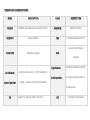
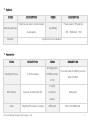
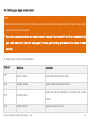
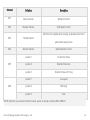
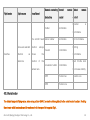
TERMS AND ABBREVIATIONS
NAME
DESCRIPTION
NAME
DESCRIPTION
GEMINI
GEMINI, dual-redundancy autopilot(M+S)
GEMINI M
Master controller
GEMINI S
Slave controller
IMU
Inertial measurement unit
Ground Control Station
COMPASS
Magnetic compass
GCS
software
Dual Remote
control Operation
Single Remote
Aircraft and gimbal controlled
control operation
by a single remote control at
Aircraft remote control (RC Transmitter) +
gimbal remote control (RC Transmitter)
the same time.
CH
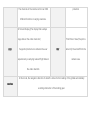
Channel; for example CH5 is channel 5.
F/S
Fail Safe; Control failure
The channels of the remote control can fulfill
protection
different functions in varying scenarios.
On Screen Display (The display that overlays
image data on the video down-link)
OSD
Supported products can enhance the user
First Person View,The pilot is
FPV
experience by overlaying relevant flight data on
able to fly the aircraft from the
camera view.
the video downlink.
In this mode, the navigation direction of aircraft is locked to the heading of the gimbal automatically
carefree
avoiding obstruction of the landing gear.
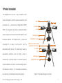
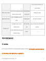
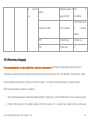
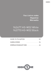
1 Product Introduction
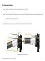
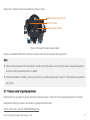
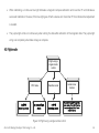
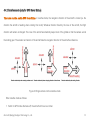
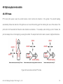
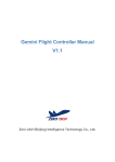
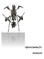
The HighOne-Pro is an all in one, fold-able 4-axis
aerial photography aircraft system researched and
developed by a professional photographer ZERO
GPS
TECH. It integrates the Gemini professional flight
propeller
arm
control autopilot and carries the Z1400 (GH3) 3-axis
landing gear
brush-less gimbal. The HighOne-Pro is small and
Gimbal(front view)
convenient, it is easy to carry and it can fly
immediately after delivery. It is particularly suited to
specialized conditions such as flying close to
obstructions, in narrow areas or in enclosed spaces
parachute case(including
parachute and spring)
front view
back view
propeller
arm
landing gear
Gimbal(back view)
such as stadiums or indoors. It can be widely used in
the television industry, for commercial promotions
and all kinds of professional aerial photography.
Zero UAV (Beijing) Intelligent Technology Co., Ltd.
Figure 1 Schematic Diagram of copter
1
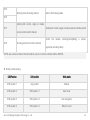
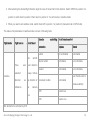
2 Product List (subject to the real parts)
Standard
ITEMS
DESCRIPTION
ITEMS
Frame (including
motors and electronic Arm(M1-M4),landing gear,copter body
Flight control
speed controls (ESCs))
Gimbal
Z1400
Wifi is for Gemini M and Gemini S is
Wi-fi module (WLAN)
individually(Wifi antenna is in the
accessory bag)
S-BUS converter
Normal receiver connect to the FC or
module
gimbal by this module
Propeller
18×5.5inch Carbon fiber
Zero UAV (Beijing) Intelligent Technology Co., Ltd.
GPS module
DESCRIPTION
GEMINI M (Master controller),
GEMINI S (Slave controller)
There is GPS module for Gemini M and
Gemini S individually
Power Supply
Main Power Supply Unit,
Module
Gimbal Power Supply Unit
OSD
ZerOSD mainframe and its wiring
landing gear
retracts
Left and right retractable landing gear
2
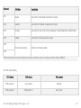
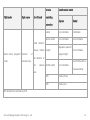
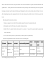
Optional
ITEMS
DESCRIPTION
ITEMS
DESCRIPTION
Parachute can open to protect camera
Security parachute
Power supply to FC,gibal,etc.
Lipo Battery
in emergency
Data link
(6S,16000mAh,15C)
Lengthen the control distance.
Accessories
ITEMS
DESCRIPTION
ITEMS
3P merging line
Flashlight hot shoe
To fix the camera
FUTABA dual pin
L=150
DESCRIPTION
10 pcs with label of S-BUS,2 pcs with
label of S-BUS
S - BUS
WiFi antenna
It need to connected with wifi
conversion
Spare parts
module
U disk
《HighOne-Pro manual》included
Zero UAV (Beijing) Intelligent Technology Co., Ltd.
HDMI lead
GH3 / GH4 HDMI lead,
3
Connect gimbal and camera video
output interface
USB to serial converter
Magic belt with buckle
Disclaimer card
Used to firmware upgrade,parameter Product certificate
adjustment and wifi setting
2 belts, 25×400MM,be used to fix
+ warranty card
Maintenance record
Propeller gasket
Be used to fix propeller
One English version and one
WiFi information
Be used to label WIFI model,SSID and
Chinese version,
card
password
Screws
——
battery
Be used to label danger,warning and
disclaimer clauses
3 Before flight (Important)
3.1 Installations
All of the cables of HighOne-Pro is connected well before sending out of factory, don’t change the connections of cables, just
do as the following and then HighOne-Pro can be adjusted to fly:
Zero UAV (Beijing) Intelligent Technology Co., Ltd.
4
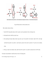
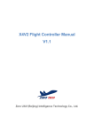
3.1.1 Landing gear installations
Step1, fix the vertical pipe(long pipe) and horizontal pipe(short pipe) by a M3*10 screw
Step2, loosen four M3*25 screws, install two pipe clamp to vertical pipe, insert the spring to vertical pipe. Tighten four M3*25
screws, horizontal pipe(short pipe) should face to the head of copter.
Step3, tighten two M4*30 screws, fix the landing gear.
M3×25 Screws
(4 pcs)
pipe clamp
(2 pcs)
M4×30 Screws
(2 pcs)
vertical pipe
(long pipe)
vertical pipe
(long pipe)
horizontal pipe
(short pipe)
Figure 2 Landing gear installations
Zero UAV (Beijing) Intelligent Technology Co., Ltd.
5
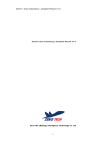
3.1.2 GPS installations
Step 1, Hold up 2 set of GPS brackets, ensure the arrow on the GPS face to the head of aircraft(between M1 and M2),. Note:
GPS bracket should be vertical to horizontal direction, GPS arrow should be parallel to copter head direction.
Step 2, Tighten the nuts on the base
GPS
GPS arrow direction
GPS bracket
pedestal nut
M1 arm
M2 arm
Figure 3 GPS installations
Zero UAV (Beijing) Intelligent Technology Co., Ltd.
6
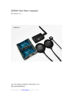
3.1.3 Quad arm installations
Step 1, Aircraft arm installation position is selected by the label of M1 to M4.
Step 2, Three pin plug should be plugged into the three hole plug of articulation base, then connect the aircraft arm and
aircraft body by screwing M4×42 bolts.
Step 3, Fasten the clamp, and one arm is finished. The same method to the other three.
clamp
finished effect piture
three hole plug
(wire)
arm
M4×42 screw (1pcs)
Figure 4 Quad arm installations
Zero UAV (Beijing) Intelligent Technology Co., Ltd.
7
3.1.4 Propeller installations
Propeller is in the down position, gasket is in the up
position, tighten 2 set of M3×14 bolts, it’s finished.
Anticlockwise propellers for M1 and M3, clockwise
propellers for M2 and M4. Propellers rotation direction
see Figure 5。
Figure 5 Propellers rotation directions
M3×14 screw (2pcs)
propeller
gasket
motor
Figure 6 Propeller installations
Zero UAV (Beijing) Intelligent Technology Co., Ltd.
8
3.1.5 Gimbal installations
Gimbal installation:Carbon plate and connector between copter and gimbal is fixed by 8 set of M8×8 round hexagonal
socket screws.
Connector between
copter and Gimbal
M3×8 screw (8 pcs)
damper ball
Gimbal dead plate
Figure 7 Gimbal installations
Zero UAV (Beijing) Intelligent Technology Co., Ltd.
9
3.1.6 Camera installations
Step1, install the hot shoe to the slot of camera.
slot
hot shoe
Figure 8 push the hot shoe into the slot
Step2, fix the camera to the upper pendant by screws in figure
camera upper pendant
2×8PT screw (2×10PT screw for old version)
3×8PT screw (3×6PT screw for old version)
Figure 9 fixing with upper pendant
Zero UAV (Beijing) Intelligent Technology Co., Ltd.
10
Step3, fix the camera to the lower pendant by screws in figure
British system screw 1/4×10
4×12PT screw
camera lower pendant
Figure 10 fixing with camera lower pendant
Step4, use standard HDMI video switch line to Gimbal video port and camera video output port
Note:
Take out the peripherals of the camera(such as filter and hood),camera center of gravity need to be adjusted again by
customer if other peripherals need to be added.
Check the installation of battery ,memory card and focus; shutter speed need to be set to 1/120s,otherwise may lead to
jelly or jitter.
3.1.7 Camera center of gravity adjustment
HighOne-Pro has got center of gravity with GH3 camera and Lumix G 14mm f/2.5 lens when leaving factory.It should be
readjusted if changing camera or lens.Center of gravity adjustment video:
http://v.youku.com/v_show/id_XODkwMjc5ODky.html
Zero UAV (Beijing) Intelligent Technology Co., Ltd.
11
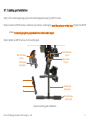
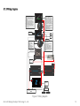
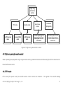
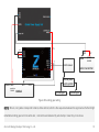
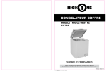
3.1.8 Wiring diagram
·
·
·
Main Controller Circuit Board
EXT1
The Controller Circuit Board is mounted in
the centre of the Aircraft Centre Plate by
pasting("front" arrow point to forward of
aircraft).
It should be ensured that all of flight
controller terminals are uncovered so as to
facilitating wiring and firmware upgrading.
After finalizing the position of flight
controller,it's advised that completing the
wiring and software setting before fixing
them in position.
·
EXT2
·
·
GPS Module
GPS and Magnetic Compass
module should be kept away from
other electronic equipments
because it's Magnetically Sensitive
Equipments.It also should be
installed by the original GPS frame.
For it's sensitive to shaking,GPS
should be installed firmly.Logo side
should be upward and small arrow
should face forward,without
extending GPS line.
Flight controllers could only work
after GPS installation.
white
red
brown, black
Electronic Speed
Controllers(M1-M4)
extension
port
extension
port
S-BUS receiver
LED Indicator Light
LED Indicator Light
Receiver
·
LED Indicator Light
should be installed in a
convenient
position,away from
GPS,ensuring it could be
seen during flighting.
Set up channels of
aileron,elevator,throttle and rudder on
the remote controller.
The receiver(support S-BUS) get the
power from flight controller directly
instead of External Power Source.
S-BUS converter should be chossen from
manufacturer if there isn't S-BUS
receiver.
·
·
Connect to the vedio input line
of GIMBAL(brown, white)
5.7V
Gimbal and
frame can be
divided here
Aviation plug switch line
com3
WiFi module
+
Power
-
6S battery
Parachute
signal
Parachute
steering engine
5.7V
white
red
Brown, black
S-BUS receiver
AV/vedio Power
supply to
Gimbal
DATA
Gimbal
CLOCK
Internal power
supply system
left landing gear
right landing gear
Figure 11 Wiring diagram
Zero UAV (Beijing) Intelligent Technology Co., Ltd.
12
NOTE: Signal wire of retractable landing gear could be connected with empty channel of gimbal receiver, or it also could be
connected with empty channel of copter receiver.
3.1.9 NOTICE
1. The Gemini flight controller and Gimbal controller both use the 5.7v power supply. If the main voltage supply from the 6s
battery is used the equipment will be fried immediately.
2. Please be sure to use a 6S LIPO battery to supply power to the gimbal. If a 4S or 5S battery is used, the gimbal will have
insufficient strength, will shake and behave abnormally.
3. The XT90 power supply connector may easily become dirty and have a poor contact making the wires become too hot
after a flight. This may be rectified by:
– Regularly clean with ethyl alcohol to eliminate carbon traces after sparking.
– Replace the anti-ignition connectors using the genuine AMASS variety.
4. There is COM port for each of the main controller and slave controller of HighOne-Pro, the extension cord of main
controller is M-COM, and the slave controller is S-COM. When upgrading the flight control firmware, insert the USB line
into its corresponding COM interface to start the upgrade operation (when upgrading the main controller, the OSD data
wire should be disconnected).
Zero UAV (Beijing) Intelligent Technology Co., Ltd.
13
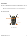
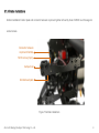
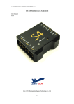
5. When installing the battery, please pay attention to the following:
a battery need to be installed in the tail of the copter, output line direction should be vertical to copter head.
b Battery should be tighten by the fixing strap, otherwise it have the risk of battery loosen.
6. After connecting all wires, connect the battery, supplying power to the flight controller and power to the system at the
same time so as to avoid restarting the flight control and generating an error.
arm M3
arm M4
battery
bandage (2 pcs)
gimbal (back view)
landing gear
Figure 12 Battery installation
Zero UAV (Beijing) Intelligent Technology Co., Ltd.
14
3.2 GCS installation (ground control station)
3.2.1 Installation of Mobile GCS
Android mobile GCS should be installed as follows:
1.
Download YS-GCS Android mobile software from the download section in the
support zone of the official website (www.zerouav.com).
2.
Automatically install the software by clicking on the APK file in the file
manager. The ground station App will appear on the mobile device desktop
after installation as shown in Figure13. The GCS must be installed in the
Figure13 GCS
(ground control station)
memory of the mobile.
3.2.2 Installation of PC GCS
Download the YS-GCS PC software from the download section in the support zone of the official website (www.zerouav.com).
After decompressing, double-click the ZERO-GCS Rotor Ground Station.exe file to install the program.
Zero UAV (Beijing) Intelligent Technology Co., Ltd.
15
3.3 WIFI Configuration
3.3.1 WIFI Communication Mode
The Gemini Wi-Fi system can support two communication modes: point-to-point (P2P) and router. The delivery default setting
is point-to-point mode with an SSID of ZERO-TECH and no password.
After the link is completed all flight data will be recorded to the ground station. The file with the extension of “.hjext2” can be
found in the directory “YShj” in the root directory of a mobile device or in the file folder “Hj” in the PC ground station software
package. This file can be replayed and analyzed in the PC GCS application.
3.3.2 WIFI Communication link
A Wi-Fi configuration tutorial can be found at: http://v.youku.com/v_show/id_XNTE2OTY4MjQ4.html.
Zero UAV (Beijing) Intelligent Technology Co., Ltd.
16
3.4 Setting up the Remote control transmitter (taking FUTABA remote controller for example)
Your RC transmitter (TX) must use “fixed-wing mode”, do not set up any mixes. If using a Futaba TX, none of the channels
should be reversed (except the channel of retractable landing gear). JR, Tiandifei and possibly other remote controls should
have all channels reversed. Video refer to: http://www.tudou.com/programs/view/e1ai526Mbt4/
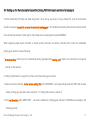
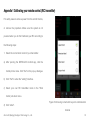
When operating single remote controller or double remote controller, the remote controller which control the retractable
landing gear need to be set as following:
1.wire connection, control line on the retractable landing gear(label with landing gear) need to be connected to correspond
channel on the receiver.
2. Side lay HighOne-Pro or support it by frame, hand the landing gear in the air.
3. Open the remote controller, do the reverse setting first: LNK→REVERSE→ set corresponding channel to REV, after reverse
setting, landing gear get down when at position 1; it’s flying status when in position 2.
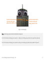
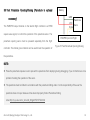
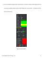
4. Then set the stroke: LNK→END POINT, set the two middle line of landing gear channel to 120(CH9 as an example in the
following picture)
Zero UAV (Beijing) Intelligent Technology Co., Ltd.
17
maximum stroke should be
120 when landing gear
getting down (default is 100)
maximum stoke should be
120 when landing gear
uplifting (default is 100)
Figure 14 stroke setting
Note: the following project should be checked after setting well:
Turn the channel of landing gear to position 1, setting is ok if landing gear get down and support the copter well.
Turn the channel of landing gear to position 2, setting is ok if landing gear uplift and be parallel to the ground.
Zero UAV (Beijing) Intelligent Technology Co., Ltd.
18
3.4.1 Setting up a single remote control
NOTE:
Manual mode is the most top priority. Whatever any mode, copter will switch to manual mode if CH5 switch to top position,
copter will be controlled by operator.
User need to use remote controller and receiver more than 9 channel if need to use CH1 to CH8 and retractable landing
gear. Insert control wire (label with landing gear)of landing gear to landing gear channel in the receiver of remote
controller.
Single remote controller channel definition.
Channel
Definition
Description
CH1
Aileron channel
Copter horizontal movement control
CH2
Elevator channel
Copter forward and backward control
Copter rise and fall control(rise in big throttle, fall in small
CH3
Throttle channel
throttle)
CH4
Rudder channel
Zero UAV (Beijing) Intelligent Technology Co., Ltd.
Copter circle around control
19
CH5
Working mode choosing channel
Refer to the following table
CH6
Gimbal pitch control, single or double
CH7
Gimbal pitch control, single or double remote controller switch
remote control switch channel
Control
CH8
the
camera
shooting/record(taking
a
picture,
Shooting and record control channel
begin/stop recording video)
NOTE: see remote controller channel method: power on remote controller→MOL→SERVO.
Working mode setting.
CH5 Position
CH6 position
Work mode
CH5 position 1
any position
Manual
CH5 position 3
CH6 position 1
Auto hover
CH5 position 3
CH6 position 2
Auto navigation
CH5 position 3
CH6 position 3
Return to land
Zero UAV (Beijing) Intelligent Technology Co., Ltd.
20
Single remote controller setting by following step:
1. Set both CH5 and CH6 to 3-position switches. CH5 and CH6 select the working mode of the flight control.
2. Fail Safe (F/S) should be set up with the controls in the following positions: Set both CH5 and CH6 of the remote control
to position 3. The throttle stick should be set to a position near the center (50%).
3. Set CH7 to use a lever to control the gimbal Pitch. On a Futaba this would be the RS or LS switch lever(in the side of
remote controller). Switching CH7 of copter remote controller from up to down and back to up and repeats 3 times, then
copter will be controlled by single remote controller. Gimbal will follow the real time copter direction, gimbal roll is
horizontal, gimbal pitch is controlled by CH7.To switch to double remote control back from single remote control:
repeating switching CH7 up and down 3 times.
4. Set CH8 to a 2-position switch to control the camera shutter. Taking a picture at each switch, or starting/stopping
recording.
5. Set a 2-position switch or knob switch on the remote controller to control the retractable landing gear.
3.4.2 Setting up a dual remote control
3.4.2.1 Copter remote controller settings
Double remote controller-copter remote controller channel definition
Zero UAV (Beijing) Intelligent Technology Co., Ltd.
21
Channel
Definition
description
CH1
Aileron
Get control of horizontal movement of copter
CH2
Elevator
Get control of forward or backward of copter
CH3
Throttle
Get control of rise or fall of the copter(rise in big throttle,fall in small throttle)
CH4
Rudder
Get control of circle around of copter
Work mode selection
Refer to the following table
CH5
CH6
NOTE: the method to view the channel of remote controller: power on remote controller→MOL→SERVO.
Work mode setting
CH5 status
CH6 status
Work mode
CH5 position 1
any position
Manual
CH5 position 3
CH6 position 1
Auto hover
Zero UAV (Beijing) Intelligent Technology Co., Ltd.
22
CH5 position 3
CH6 position 2
Auto navigation
CH5 position 3
CH6 position 3
Return to land
Copter remote controller setting steps
1. Set both CH5 and CH6 to 3-position switches. CH5 and CH6 select the working mode of the flight control.
2. Retractable landing gear control: If the signal input wire of retractable landing gear control module connect to empty
channel, then the corresponding channel on the copter controller is set to two-position switch or knob switch, using to
control the retracting of landing gear.
3. Fail Safe (F/S) should be set up with the controls in the following positions:
Set both CH5 and CH6 of the remote control to position 3. The throttle stick should be set to a position near the center
(50%).
NOTE: Manual mode have the highest priority. Flight status will get back to manual mode whatever mode it is, copter will be
controlled by the operator.
3.4.2.2 Gimbal remote controller setting
Double remote controller-Gimbal remote controller channel definition
Zero UAV (Beijing) Intelligent Technology Co., Ltd.
23
Channel
Definition
Description
CH1
Aileron channel
Gimbal roll control
CH2
Elevator channel
Gimbal pitch control
Add force to the gimbal when pushing up,decrease force to the
CH3
Throttle channel
gimbal when pulling down
CH4
CH5
CH6
direction channel
Gimbal direction control
position 1
No direction follow
position 2
Direction follow lock
position 3
Direction follow with 5° lag
position 1
Low speed
position 2
Mid range
position 3
Fast
NOTE: method to view remote controller channel: power on remote controller→MOL→SERVO.
Zero UAV (Beijing) Intelligent Technology Co., Ltd.
24
Gimbal remote controller setting step
1. Set a 3-position switch to CH5,controlling gimbal work mode; set a 3-position to CH6,adjusting gimbal revolving speed.
2. Retractable landing gear control: If the signal wire of retractable control module is plugged in an empty channel of
gimbal receiver, then correspond channel is set into 2-position switch or knob switch, for controlling the retractable
landing gear.
3. CH8 is set to a 2-position switch, controlling the shooting and recording.
3.5 Energizing
3.5.1 Inspecting the aircraft prior to energizing
Make sure of 6s battery, remote controller sufficient.
Check propeller nuts are tight – if they are too loose a propeller may be thrown off.
Check motor Installation is secure and none of the motors are loose.
Check the landing gear is securely attached and all screws tightened.
Check the centre of gravity after securing the battery.
Check all connectors and cables are secure.
Zero UAV (Beijing) Intelligent Technology Co., Ltd.
25
Check the arrows on the flight control and the GPS are pointing to the front of the aircraft and are both secure.
Check the centre of gravity of the gimbal. The camera should be stable and centered. When the gimbal is not powered the
camera should maintain its position in any condition of pan, tilt or roll.
Check that motor mixing control is correct.
Check the angle status, number of GPS satellites locked and other relevant data in the ground station.
3.5.2 Power-on operation steps
The aircraft may be energized following these steps.
1. The remote control must be switched on first, switch to manual mode and pull the throttle back to zero. Now connect
power to the motors and flight controller. The flight control system will now start up. The default value is operation by
dual remote control.
2. Check that the flight control is normal; check that the type of aircraft and its reported angle are correct in the Android
ground station app.
– Android GCS: This can be checked in the “data” section of the app. All values should be active. (Not frozen!). The
type of aircraft can be checked in the "parameter" section of the app.
– PC GCS: select “file” then “open Wi-fi”. Pop out the flight data column. In “Gemini data" check that the flight control
Zero UAV (Beijing) Intelligent Technology Co., Ltd.
26
is normal; in "other data" the angle status may be checked. Select "setting" then "parameter setting" to check that
the type of aircraft is correct.
3. Confirm in the ground station data section that CH5 and CH6 of the aircraft transmitter are switching to the correct flight
modes; and that the setting of fail-safe (F/S) is correct by switching off the transmitter and check that the flight status is
displayed as “Return to land”.
4. If you are using the HighOne-Pro for the first time you need to carry out the following operations:
Conduct stick-calibration on all channels of the aircraft remote control transmitter. Please refer to Appendix 1.
“Calibration of remote control” for detailed instructions.
Switch on the parachute so that it is able to open automatically.
On the Android ground station: click the "default" button in the "parameter" section.
On a PC ground station: select "settings" then under "parameter settings", in the pop out window, click the "restore
defaults" button.
Zero UAV (Beijing) Intelligent Technology Co., Ltd.
27
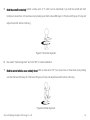
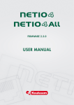
5. In order to increase gimbal stability, manual detection of
orientation should be carried out before starting. By
hand gently rotate each axis of gimbal for 360° and then
level the camera. The lens should stay pointing forward
and note the correct upward and downward direction.
NOTE: Each time the aircraft is energized the gimbal
Figure 15 Gimbal initialized
must be initialized as described above.
6. Depending upon whether you are adopting the single or dual remote control method you need to carry out the following
operations:
Zero UAV (Beijing) Intelligent Technology Co., Ltd.
28
Single Remote control operation
a) Switch CH7 on your aircraft remote control from Maximum to minimum. Now switch 3 times in rapid succession to
enter single remote control operation. The gimbal will now be controlled by the aircraft remote controller. Repeat
this operation by switching 3 times again to exit single remote control operation and enter double remote control
operation.
b) To check whether you have successfully entered single remote control operation or not: slightly raise the throttle
stick, if all is in order, the gimbal will start stabilizing. It will tilt and roll to stay level and the CH7 switch will control
gimbal tilt.
c) When the throttle is reduced to zero the gimbal will cease stabilisation.
Dual remote control operation
Push the throttle stick on the Gimbal remote control to its maximum. The gimbal will be at maximum stability. Use the
gimbal remote control to regulate the roll, tilt and pan of the gimbal.
NOTE:: If the gimbal fails to maintain roll and tilt stability after initialization it is necessary to increase the throttle control until
the camera maintains a level horizontal position and directional stability..
Zero UAV (Beijing) Intelligent Technology Co., Ltd.
29
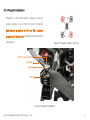
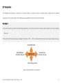
3.6 Test Parachute Opening/Closing (Parachute is optional
Battery
GND
accessory)
VCC
The PAR/PHO output channel on the Gemini flight controller is a PWM
Signa
controller. The mobile ground station can be used to test the operation of
Servo
l
square wave signal, to control the operation of the parachute servo. The
parachute opening servo must be powered separately from the flight
Parachute
PAR/PHO port on Flight
Control
Figure 16 Test Parachute Opening/Closing
the parachute.
NOTE:
Press the parachute capsule cover to prevent the parachute from deploying during debugging, if you do this there is not a
problem checking the operation of the servo.
The parachute must be folded in accordance with the parachute folding video. It is the responsibility of the user the
parachute does not open because it has been improperly folded. Parachute folding
video:http://v.youku.com/v_show/id_XNjgxNTQ1OTU2.html
Zero UAV (Beijing) Intelligent Technology Co., Ltd.
30
3.6.1 Android GCS test
The parachute operation can be
tested as follows:
1.
Click “Test Open Parachute” in
the “Settings” interface to pop up
the confirmation dialogue box, as
shown in Figure17.
2.
Click
“OK”,
to
open
the
parachute capsule.
3.
Click “Test Close Parachute” and
click “OK”, as shown in Figure18.
NOTE: The Gimbal controller does
not support the parachute.
Zero UAV (Beijing) Intelligent Technology Co., Ltd.
Figure17 Android GCS test-open
Figure18 Android GCS test-close
31
3.6.2 PC GCS test
The parachute operation can be tested as follows:
1.
Select settings→Test Parachute→Open Parachute, then parachute case open.
2.
Select settings→Test Parachute→Close Parachute, then servo close.
NOTE: The Gimbal controller does not support the parachute.
3.7 Calibrating the Magnetic Compass
3.7.1 Using the Android GCS
NOTE:
The magnetic compass must be calibrated before the first flight after installation of the Gemini flight controller.
Calibration should be carried out in a clear space outside; calibration should not be done indoors or in an environment
with strong magnetic fields, such as in the presence of cars or shipping containers.
You should also calibrate after re-arranging components in your aircraft or if you find it flies in circles.
Compass calibration does not need to be done every time you fly, or if you upgrade firmware without changing hardware
position. However it should be done when components are moved or if the aircraft flies in unexpected ways.
Zero UAV (Beijing) Intelligent Technology Co., Ltd.
32
Compass calibration is carried out in three steps: horizontal calibration, vertical calibration and storage of magnetic compass
data. Instructions for each stage can be found in the status bar at the top “Settings” interface, as follows:
1.
Switch the transmitter to manual
mode
and
pull
the
throttle
to
minimum.
2.
Click “Settings” to enter the settings
interface, as shown in Figure19.
3.
Click “Magnetic compass” to open
Figure20 Magnetic Compass Calibration
the calibration dialog box, as shown
Interface
in Figure20.
4.
Select “Horizontal Alignment” and to
click
“OK”
to
start
horizontal
Figure19 data interface
calibration.
Zero UAV (Beijing) Intelligent Technology Co., Ltd.
33
5.
Hold the aircraft horizontally (within a status error of 5° which can be maintained if you hold the aircraft with both
hands),turn around two or three times slowly making sure that the blue LED stays lit. If the blue LED goes off, stop and
adjust the aircraft, before continuing.
Figure21 Horizontal Alignment
6.
Now select “Vertical Alignment” and click “OK” for vertical calibration.
7.
Hold the aircraft with the nose vertically down(within a status error of 5°) turn around two or three times slowly making
sure that the blue LED stays lit. If the blue LED goes off, stop and adjust the aircraft, before continuing.
Figure22 Vertical Alignment
Zero UAV (Beijing) Intelligent Technology Co., Ltd.
34
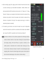
8.
Select “Save Alignment” in the dialogue box and click “OK”.
9. You will need to wait for the flight controller to process the recorded magnetic data. A purple LED will show during the
processing. When the purple light goes out, calibration is complete. The ground station will switch to the remote control
interface automatically and spend a few seconds calculating. Then it will display two circles, one blue and the other red,
as indicated in the following figures: The superposition of two circles, red and blue indicates successful calibration. If this
is not the case you need to start again with a new calibration operation.
Figure23 figure shows excellent, qualified and disqualification
3.7.2 Compass Calibration Using a PC Ground Station
NOTE:
The magnetic compass must be calibrated before the first flight after installation of the Gemini flight controller.
Calibration should be carried out in a clear space outside; calibration should not be done indoors or in an environment
with strong magnetic fields, such as in the presence of cars or shipping containers.
Zero UAV (Beijing) Intelligent Technology Co., Ltd.
35
You should also calibrate after re-arranging components in your aircraft or if you find it flies in circles.
Compass calibration does not need to be done every time you fly, or if you upgrade firmware without changing hardware
position. However it should be done when components are moved or if the aircraft flies in unexpected ways.
Compass calibration is carried out in three steps: horizontal calibration, vertical calibration and storage of magnetic compass
data. Instructions for each stage can be found in the status bar at the top “Settings” interface, as follows:
1.
Switch the transmitter to manual
mode and pull the throttle to
minimum.
2.
Select “Settings(S) ” →“ Magnetic
Compass (M)”for the “Magnetic
Compass Alignment”window as
shown in Figure24.
3.
Click “Horizontal Alignment” for
horizontal calibration, as shown
in Figure25.
Zero UAV (Beijing) Intelligent Technology Co., Ltd.
Figure24 Alignment window
Figure25 Horizontal Alignment
36
4.
Hold the aircraft horizontally (within a status error of 5° which can be maintained if you hold the aircraft with both
hands),turn around two or three times slowly making sure that the blue LED stays lit. If the blue LED goes off, stop and
adjust the aircraft, before continuing.
Figure26 Horizontal Alignment
5.
Now select “Vertical Alignment” and click “OK” for vertical calibration.
6.
Hold the aircraft with the nose vertically down(within a status error of 5°) turn around two or three times slowly making
sure that the blue LED stays lit. If the blue LED goes off, stop and adjust the aircraft, before continuing.
7.
Select “Save Alignment” in the dialogue box and click “OK”.
Zero UAV (Beijing) Intelligent Technology Co., Ltd.
37
copter
head
Figure27 Vertical Alignment
8. You will need to wait for the flight controller to process the recorded magnetic data. A purple LED will show during the
processing. When the purple light goes out, calibration is complete. The ground station will switch to the remote control
interface automatically and spend a few seconds calculating. Then it will display two circles, one blue and the other red,
as indicated in the following figures: The superposition of two circles, red and blue indicates successful calibration. If this
is not the case you need to start again with a new calibration operation.
Figure28 figure shows excellent, qualified and disqualification
Zero UAV (Beijing) Intelligent Technology Co., Ltd.
38
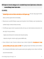
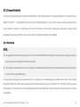
3.8 How to unlock motors before flight
NOTE:
In Beijing, if you are in the area inside the 5 ring or near various airports it is not possible to arm the motors using CSC.
If you arm the motors using CSC, and do not operate the throttle stick within five seconds then the motors will lock again.
You should execute CSC again to unlock the motors.
Motor arming is not available if CH5 of the aircraft TX is in the middle position.
Motor arming by CSC is not available if the GPS compass and the actual compass bearing differs by more than 15°.
The parachute must be folded strictly in accordance with the instructional video. It is the user’s responsibility should the
parachute fail to deploy. A video showing how to fold the parachute is available here (take HighOne for example):
http://v.youku.com/v_show/id_XNjgxNTQ1OTU2.html
Zero UAV (Beijing) Intelligent Technology Co., Ltd.
39
These steps should be followed before unlocking the motors for flight:
1. Before takeoff, make sure the parachute is folded and placed in its container correctly.
NOTE:Operation of the parachute can be tested using the android ground station.
When commissioning press the lid of the
container so that the parachute cannot pop out. It’s operation can now be checked. For more detailed instructions see
the Gemini Flight Control Manual.
2.
Check failsafe is working. Before each flight this must be checked otherwise it will not be possible to start the motors
using the CSC.
1) Check the throttle is in mid-position. Switch off the aircraft remote control.
2) The flight status on the ground station should be reported as “return to land.” If not failsafe (F/S) should be set up again.
On the Android ground station: check in the "data' section.
On a PC ground station: select “view" → "dashboard," check on the right side of the dashboard.
3) Power up the remote control.
Zero UAV (Beijing) Intelligent Technology Co., Ltd.
40
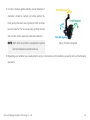
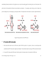
3. After unlocking using CSC, slightly push the throttle. Check that motor mixing
is normal. According to your transmitter mode (Mode 1, Mode 2, Mode 3, etc.)
when executing the CSC the sticks can be moved in a “\/” shape or a “/\” shape.
Take the “/\”shape as an example; the throttle stick should be reduced to the
minimum and pushed to the left, the elevator stick should be reduced to the
minimum and pushed to the right. This example would apply to a Mode 2
transmitter (American standard)
4. The Gemini ground station can monitor the state of two sets of independent
sensors at the same time, when the user observes that at least seven satellites
are in view of the GPS it is possible to arm the motors and take off.
NOTE: If remote controller can’t be unlocked, please do the following checking:
remote controller should be closed when checking the newest firmware
(F/S setting correctly, CH5 and CH6 are on position 3, throttle is in the
middle position). Combination stick command after checking and then
motor will start, otherwise it refused. It needn’t to be checked again except
Figure 29 GCS- satellites
energizing. But it should be checked again when power is disconnected. It
also should be checked again to the remote controller settings
Zero UAV (Beijing) Intelligent Technology Co., Ltd.
41
4 Flight operation (Important)
4.1 Careful attention during flight
a. Before taking off, check that the following parameters are all reported as normal by the ground station data section:
"motor balance" “actual accelerator rudder", "magnetic compass”, GPS and IMU.
– When there is no wind the aircraft should maintain position automatically and the "motor balance" being displayed
as "good" for most of the time would be regarded as normal.
– The value of "actual accelerator rudder" should display around 50.
– Magnetic compass, GPS and IMU should be in “no failure” status, the GPS satellite number should be 7 or more,
and the difference between the magnetic heading of this machine and the actual magnetic heading angle should
not exceed 15°.
b. The HighOne-Pro leaves the factory with the default values in the controller. If you wish to restore default values after
changing any parameters you can do so in the ground station.
Zero UAV (Beijing) Intelligent Technology Co., Ltd.
42
– On an Android ground station: click the "default" button in the “parameter" interface.
– On a PC ground station: select "settings" → "parameter setting", pop out the parameter setting window and click the
“restore default" button.
c. For safety reasons, when in settings status it is not possible to start the motors.
d. It is only possible to exit return-to-land mode after switching back to manual operation.
e. Do not reduce the throttle to minimum when in manual flying mode. Doing so will cause the motors to stop and the
aircraft to crash.
f. If the aircraft is not stable in manual mode do not switch to GPS mode as this will make it even more unstable.
NOTE:
According to your preference you can select to use a single remote control or two remote controls to operate.
The
method for switching between these modes is explained at step 6 in “Energizing”.
This manual is only aimed at introducing for professionals, the Zero UAV Z-series gimbals. For other basic flight
operations please refer to the Gemini flight control manual
Zero UAV (Beijing) Intelligent Technology Co., Ltd.
43
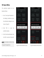
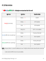
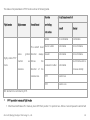
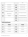
4.2 LED Status Indications
RED+BLUE (or GREEN) LED——indicating the current operational state of the aircraft
Light colour
Light status
Operational status
3 flashes
•••
No GPS
2 flashes
••
GPS 5 satellites
1 flash
•
GPS 6 satellites
Red light (for all modes)
Red light out
GPS 7 or more satellites
2 flashes
••
Hovering at fixed height
1 flash
•
User in operation
2 flashes
••
Hovering at fixed point
1 flash
•
User in operation
Blue light (GPS mode, non-positioning)
Green light (GPS mode, in positioning)
NOTE:Only take off after 7 or more GPS satellites are in view. The flight controller will use the take-off position as the home
location when the GPS first locks in to seven satellites.
Zero UAV (Beijing) Intelligent Technology Co., Ltd.
44
White LED——indicating a large status error or a loose connection to the GPS module
Action required when the white light comes on:
If the light comes on when the aircraft is suffering violent movement but goes out when it retains stability than you can
continue the flight normally.
Land the aircraft as soon as possible if the white light shows continuously and check the GPS connection. Zero the
gyro in the GCS if there is a status error.
RED LED——Low voltage alarm
The red light will flash quickly as a low battery voltage alarm. It shows as a solid light in an emergency situation of
extreme low voltage.
A continuous red light showing when the aircraft is on the ground, indicates the failure of the barometer to initialize.
You must restart the flight controller.
BLUE+PURPLE LED——Magnetic field verification
Zero UAV (Beijing) Intelligent Technology Co., Ltd.
45
When calibrating, a continuous blue light indicates a magnetic compass calibration error less than 5° and indicates a
successful calibration. However, if the blue light goes off with a status error more than 5° this indicates that adjustment
is needed.
The purple light will be on continuously when storing the data after calibration of the magnetic data. The purple light
will go out completely when data storage is complete.
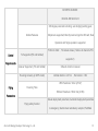
4.3 Flight mode
Flight using a
single remote
control
FPV mode
in GPS
hovering mode
in manual flight
mode
Carefree mode
Aerial rocker
function
in GPS
hovering mode
The default waypoint flying value,
when using a Zero UAV Z series
brushless gimbal, is the “Aerial
rocker” function
Figure 30 Flight using a single remote control
Zero UAV (Beijing) Intelligent Technology Co., Ltd.
46
Flight using
dual remote
controls
FPV mode
in GPS hovering
mode
Carefree mode
in manual flight
mode
in GPS hovering
mode
Aerial rocker
function
The default waypoint flying value,
when using a Zero UAV Z series
brushless gimbal, is the “Aerial
rocker” function
Panorama
photography
Enter carefree mode and increase
the gimbal stability to maximum
(i.e. push the throttle stick up to its
maximum level).
Figure 31 Flight using dual remote controls
4.4 Flight using a single remote control
When operating the equipment using a single remote control, gimbal tilt should be controlled using the CH7 channel lever on
the aircraft remote control.
4.4.1 FPV mode
FPV mode (first person view) the aircraft remote control controls the direction of the gimbal. The aircraft heading
Zero UAV (Beijing) Intelligent Technology Co., Ltd.
47
automatically follows the direction of the gimbal so as to avoid the landing gear from blocking the view of the camera. The
pitch and roll of the aircraft will follow the video direction as reference.
For example, when circling a point of interest, the
pilot can always focus on the target by just using the rudder. The autopilot will control aileron, elevator, height and distance.
Figure 32 Single remote control-FPV mode
FPV operation in GPS hovering mode
1. After the aircraft enters hover in GPS mode, switch CH5 from position 3 to position 2, after a 2 second pause the
aircraft will enter FPV mode with a high level of stability. The aircraft will remain hovering in GPS mode at that moment.
2. To leave FPV mode switch CH5 back to the first position for manual mode or 3rd position for GPS hover.
Zero UAV (Beijing) Intelligent Technology Co., Ltd.
48
The status of all parameters in FPV mode is shown in following table.
Remote
Flight mode
Flight course
Aircraft head
Aircraft remote control
controlling
Aircraft
Gimbal
Not controllable
Controllable
Controllable
Not controllable
Controllable
Not controllable
instruction
Rudder
The aircraft head Aileron rudder
Takes
gimbal direction
always Elevator
Highly stable FPV
direction
as follows
the
mode
Push throttle stick to
Accelerator rudder
reference
direction
of
camera lens.
Controllable
the
increase stability
CH5
Position two
CH6
Position one
NB. Gimbal tilt is controlled by CH7.
FPV operation in manual flight mode
1. After the aircraft takes off in manual, place CH5 from position 1 to position two. After a 2 second pause the aircraft will
Zero UAV (Beijing) Intelligent Technology Co., Ltd.
49
enter FPV mode with a high level of stability. Unlike when in GPS automatic hover status, the aircraft will remain in
manual mode..
2. To leave FPV mode, switch CH5 back to the first position for manual mode.
The status of all parameters in manual mode is shown in following table.
Flight mode
Highly stable
FPV mode
Flight course
Takes gimbal
direction
reference
as
Remote
Aircraft head
The
aircraft
direction
head
always
controlling Aircraft remote control
instruction
Airplane
Gimbal
Rudder
Not controlled
Controlled
Aileron rudder
Controlled
Not controlled
Elevator
Controlled
Not controlled
follows the direction of Accelerator rudder
the camera lens.
Controlled
CH5
Position two
CH6
X
Push
throttle
stick
to increase stability
NB. Gimbal tilt is controlled by CH7.
Zero UAV (Beijing) Intelligent Technology Co., Ltd.
50
4.4.2 Carefree mode (only for GPS Hover Status)
This mode must be used in GPS Hover Status. In carefree mode, the navigation direction of the aircraft is locked (i.e. the
direction the aircraft is heading when entering this mode). Whatever direction faced by the nose of the aircraft, the flight
direction will remain unchanged. The nose of the aircraft automatically keeps track of the gimbal so that the camera avoids
the landing gear. The elevator and aileron of the aircraft take the navigation direction of the aircraft as reference.
Figure 33 Single remote control-carefree mode
Enter carefree mode as follows:
1. Switch to GPS mode after take-off, the aircraft will hover as normal.
Zero UAV (Beijing) Intelligent Technology Co., Ltd.
51
2. After selecting the desired flight direction align the nose of the aircraft in this direction. Switch CH5 from position 3 to
position 2, switch back to position 3 then return to position 2. You will now be in carefree mode.
3. When you need to exit carefree mode, switch channel 5 to position 1 or position 3 (manual mode or GPS mode).
The status of all parameters in carefree mode is shown in following table.
Remote
Flight mode
Flight course
Aircraft head
The
Take
selected
controlling Aircraft remote control
aircraft
instruction
Airplane
Gimbal
Rudder
Not controllable
Controllable
Aileron rudder
Controllable
Not controllable
Elevator
Controllable
Not controllable
user head direction
always follows
carefree
Push throttle stick to
direction
as the direction of Accelerator rudder
Controllable
increase stability
reference
the
camera
lens.
CH5
Position two
CH6
Position one
NB. Gimbal tilt is controlled by CH7.
Zero UAV (Beijing) Intelligent Technology Co., Ltd.
52
4.4.3 Aerial rocker function
The default waypoint flying value, when using a Zero UAV Z series brushless gimbal, is the “Aerial rocker” function. Rocking
the elevator stick backwards and forwards controls the speed of waypoint flight.
When in the aerial rocker function, the aircraft remote control controls the direction of gimbal, the aircraft head tracks the
gimbal direction. Pushing the elevator stick will make the aircraft fly according to the scheduled way point route; the greater
the degree of elevator input the higher the flight speed. Releasing the stick to centre will make the aircraft return to hover.
After complete all way points, releasing the stick to centre will cause the aircraft to return to the 1st way point and hover.
Enter the aerial rocker function as follows:
1. Setup your waypoint route on the GCS map interface, upload the route to the autopilot and verify.
2. After takeoff, switch to GPS mode and hover.
3. Switch CH6 from position 1 to position 2. Pause for five seconds and the aerial rocker function will enable.
4. To exit, return CH5 to position one (manual mode) or CH6 to position one (GPS mode).
The status of all parameters in aerial rocker mode is shown in following table.
Zero UAV (Beijing) Intelligent Technology Co., Ltd.
53
Remote
Flight mode
Flight course
Aircraft head
Aircraft remote control
controlling
Airplane
Gimbal
Rudder
Not controllable
Controllable
Aileron rudder
Not controllable
Not controllable
instruction
Head direction
Regulates speed of
always
Aerial rocker (waypoint Direction
follows Elevator
Not controllable
waypoint flight
of
the direction of
route)
planned route
Push throttle stick to
the
camera Throttle rudder
Not controllable
increase stability
lens.
CH5
Position three
CH6
Position two
NB. Gimbal tilt is controlled by CH7.
Zero UAV (Beijing) Intelligent Technology Co., Ltd.
54
4.5 Flight using dual remote controls
4.5.1 FPV mode
FPV mode (first person view) the aircraft remote control controls the direction of the gimbal. The aircraft heading
automatically follows the direction of the gimbal so as to avoid the landing gear from blocking the view of the camera. The
pitch and roll of the aircraft will follow the video direction as reference.
For example, when circling a point of interest, the
pilot can always focus on the target by just using the rudder. The autopilot will control aileron, elevator, height and distance.
Figure 34 Dual remote controls-FPV mode
Zero UAV (Beijing) Intelligent Technology Co., Ltd.
55
FPV operation in GPS hovering mode
1. Switch CH5 of the gimbal remote control to position 1, the gimbal will not be in tracking mode.
2. After the aircraft enters hover in GPS mode, switch CH5 on the aircraft controller from position 3 to position 2, after a 2
second pause the aircraft will enter FPV mode with a high level of stability. The aircraft will remain hovering in GPS
mode.
3. To leave FPV mode switch CH5 on the aircraft controller back to the first position for manual mode or 3rd position for
GPS hover.
The status of all parameters in FPV mode is shown in following table.
Remote controlling Aircraft
Flight mode
Flight course
Aircraft head
Gimbal remote control
instruction
The aircraft head Rudder
Takes
Highly
remote
control
Controllable
Not controllable
Controllable
Roll is controllable
Controllable
Pitching is controllable
gimbal
stable
direction
direction
FPV mode
always Aileron rudder
as
follows
the Elevator
reference
direction of the Accelerator rudder Controllable
Zero UAV (Beijing) Intelligent Technology Co., Ltd.
Push throttle stick
to
56
camera lens.
increase stability
CH5
Position two
Position one
CH6
Position one
X
NB:
When CH6 is shown as X changing the sensitivity of the gimbal will be invalid.
FPV operation in manual flight mode
1. Switch CH5 of the gimbal remote control to position one; the gimbal will not be in tracking mode.
2. After the aircraft takes off in manual, place CH5 from position 1 to position two. After a 2 second pause the aircraft will
enter manual FPV mode with a high level of stability. Unlike when in GPS automatic hover status, the aircraft will
remain in manual mode.
3. To leave FPV mode switch CH5 back to the first position for manual mode.
The status of all parameters in manual mode is shown in following table.
Remote controlling Aircraft
Flight mode
Flight course
Aircraft head
Gimbal remote control
instruction
Highly
stable Take
gimbal The aircraft head Rudder
Zero UAV (Beijing) Intelligent Technology Co., Ltd.
remote
control
Controllable
Not Controllable
57
FPV mode
direction
reference
as direction
always Aileron rudder
follows
the Elevator
Controllable
Roll is Controllable
Controllable
Pitch is controllable
direction of the
camera lens..
Push throttle stick
to
Accelerator rudder Controllable
increase stability
CH5
Position two
Position one
CH6
X
X
4.5.2 Carefree mode
This mode must be used in GPS Hover Status.
In carefree mode, the navigation direction of the aircraft is locked (i.e. the direction the aircraft is heading when entering this
mode). Whatever direction faced by the nose of the aircraft, the flight direction will remain unchanged. The nose of the aircraft
automatically keeps track of the gimbal so that the camera avoids the landing gear. The elevator and aileron of the aircraft
take the navigation direction of the aircraft as reference.
Zero UAV (Beijing) Intelligent Technology Co., Ltd.
58
Figure 35 Dual remote controls-carefree mode
Enter carefree mode as follows:
1. Switch CH5 of the gimbal remote control to position one; the gimbal will not be in tracking mode.
2. After takeoff switch to GPS mode and hover.
3. After selecting the desired flight direction align the nose of the aircraft in this direction. Switch CH5 on the flight
controller from position 3 to position 2 , switch back to position 3 then return to position 2. You will now be in carefree
mode.
4. When you need to exit carefree mode, switch channel 5 to position 1 or position 3 (manual mode or GPS mode).
The status of all parameters in carefree mode is shown in following table.
Zero UAV (Beijing) Intelligent Technology Co., Ltd.
59
Remote controlling Aircraft
Flight mode
Flight course
remote Gimbal
remote
Aircraft head
instruction
control
control
Direction
Rudder
is
Controllable
Controllable
The aircraft head Aileron rudder
Take user selected direction
direction
reference
as follows
direction
of
Roll Controllable
Pitching
always
Elevator
Carefree
Controllable
Controllable
the
Controllable
the
Push throttle stick
Accelerator rudder
Controllable
camera lens..
to increase stability
CH5
Position two
Position one
CH6
Position one
X
4.5.3 Aerial rocker
The default waypoint flying value, when using a Zero UAV Z series brushless gimbal, is the aerial rocker function. Rocking
the elevator stick backwards and forwards controls the speed of waypoint flight.
Zero UAV (Beijing) Intelligent Technology Co., Ltd.
60
When in the aerial rocker function, the gimbal remote control controls the direction of gimbal, the aircraft head tracks the
gimbal direction. Pushing the elevator stick will make the aircraft fly according to the scheduled way point route; the greater
the degree of elevator input the higher the flight speed. Releasing the stick to centre will make the aircraft return to hover.
After completing all way points, releasing the stick to the centre will cause the aircraft to return to the first way point and
hover.
Enter the aerial Rocca function as follows:
1. Setup your waypoint route on the GCS map interface, upload the route to the autopilot and verify.
2. After takeoff, switch to GPS mode on the aircraft controller and hover.
3. Switch CH6 on the aircraft controller from position 1 to position 2.
Pause for five seconds and the aerial rocker
function will enable.
4. To exit, return CH5 to position one (manual mode) or CH6 to position one (GPS mode).
The status of all parameters in aerial rocker mode is shown in following table.
Flight mode
Aerial
rocker
(waypoint
route)
Flight course
Direction
planned route
Aircraft head
of
Head direction
always follows
Remote controlling instruction
Rudder
the direction of Aileron rudder
Zero UAV (Beijing) Intelligent Technology Co., Ltd.
Aircraft
remote Gimbal
control
control
Not controllable
Not controllable
Direction
remote
is
controllable
Roll is controllable
61
the
camera
lens.
Elevator
Regulates speed of Pitch
waypoint flight
is
controllable
Push throttle stick
Accelerator rudder
Not controllable
to
increase
stability
CH5
Position three
Position one
CH6
Position two
X
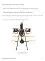
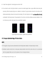
4.5.4 Panorama photography
Panorama photography is only possible when using two remote controls. Panorama photography makes it possible to
completely automate specific photography functions such stay level, pitch down 30°, pitch down 60°, pitch down 90°, taking
four photographs at each level ( 12 photos for the first 3 layers, 1 one photo for last layer making 37 copies in total ).
Panorama photography operation is as follows:
1. Enter carefree mode and increase the gimbal stability to maximum (i.e. push the throttle stick up to its maximum level).
2. Switch CH6 channel on the gimbal remote control from position 1 to position three rapidly 3 times continuously
Zero UAV (Beijing) Intelligent Technology Co., Ltd.
62
( 1→3→1→3→1→3→1) this will initiate automatic panorama photography.
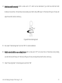
3. In panorama photography mode, the aircraft will pan automatically and the gimbal direction will keep consistent with
the direction of aircraft. The gimbal will automatically control the camera to place it in the various attitudes needed for
panorama photography.
4. After completion of the panorama sequence, the gimbal will automatically return to its level position. (The last photo
will be taken with the camera pointing vertically downwards at 90°) The aircraft will now hover. To exit the panorama
function, switch to manual mode.
4.6 Landing
During flight, staff monitoring the ground station should, at all times, keep an eye on the flight pack voltage, the balance
performance of the motors, the number of GPS satellites in view and the flight time so as to be able to remind the pilot to land
in good time. After landing, carry out the following operations:
1. Reduce the throttle stick on the gimbal remote-control to its lowest position, the gimbal will stop stabilizing.
2. Remove the power supply and by hand feel each motor to feel if any have heated more than the others. If the
temperature difference is too large, it is an indication that the motor is not installed horizontally.
Zero UAV (Beijing) Intelligent Technology Co., Ltd.
63
5 Introduction to Functions
Graphical
Functions
Introduction
presentation
Combined with Zero UAV professional flight control.
The HighOne-Pro system is integrated with a Gemini autopilot which consists of
duplicated control units, the Master Controller and a Slave Controller. Each has
its own IMU (Inertial Measurement Unit) which includes 2 separate sets of gyros,
Please refer to
accelerometers, and barometric sensors. There are also two GPS/COMPASS
Gemini (dual
units.
redundancy)
Having everything duplicated ensures maximum safety and reliability. If
any unit associated with flight control fails or loses control then the system
Autopilot Manual
automatically switches to a functioning unit. The ground station continually
monitors the status of two Controllers, and warns the user whenever a unit has
failed and the other has switched in. This built-in redundancy greatly increases
Zero UAV (Beijing) Intelligent Technology Co., Ltd.
64
safety, stability and reliability and minimizes the likelihood of accidents.
Matches the Zero UAV high-end gimbal
Combined with the newest ZERO brushless gimbal, the Z1400, the aircraft is
Please refer to Z1400
able to keep the camera completely level and stable, regardless of flying
High -End Gimbal
conditions. This high-precision camera attitude correction achieves impressive
User Manual
filming stability.
Security parachute supported
Please refer to
So as to fully ensure the safety of expensive camera equipment, Zero UAV has
designed a innovative, dedicated security parachute for the whole system which
automatically deploys in emergency. It is the 2nd tier of security, the first being
Gemini(dual
redundancy)
Autopilot Manual
the dual redundancy of the AP.
Single or dual controllers supported
Please refer to 4.4
The HighOne-Pro system supports both single transmitter control (one
and 4.5
transmitter controls the aircraft and gimbal pitch at the same time) and dual
Zero UAV (Beijing) Intelligent Technology Co., Ltd.
65
transmitter control (one transmitter controls the aircraft whilst the other
transmitter controls the roll, pitch and yaw of the gimbal). The dual control
method simplifies flying.
Highly stable FPV mode
The ZERO UAV professional autopilot works in conjunction with the gimbal
controller to produce a highly stable FPV mode. In this mode the aircraft course
Please refer to 4.4.1
heading automatically follows the gimbal heading. The elevator and aileron
and 4.5.1
controls of the RC transmitter are relative to the coordinates of the gimbal. This
simple operation ensures stable video and is very convenient for both the
cameraman and the pilot.
360° panoramic photography
When flying in “carefree” mode the pilot can utilize the fully automatic panoramic
Please refer to 4.5.4
photography function. Using this function, four layers of HD photo in a 360°
circumference can be taken in one minute (37 frames in total!) The panorama
Zero UAV (Beijing) Intelligent Technology Co., Ltd.
66
can be processed by simple splicing.
“Aerial Rocker Arm” function
An “Aerial Rocker Arm” function is available where the aircraft can, under
auto-pilot, fly a preset route whilst the camera automatically takes pictures
Please refer to 4.5.3
according to a programmed sequence. The pilot can vary the speed of flight with
just one stick on the remote control.
Landing gear retracts supported
The HighOne-Pro can utilize high strength, high load bearing retractable landing
Please refer to 6.2.5
gear which can be easily assembled and deployed using the double remote
control option.
Remote control of photo or video acquisition
Camera mode, should be set before take-off , during flight, CH8 of the remote
Please refer to 3.4
control can be used to switch between photo or video control.
Zero UAV (Beijing) Intelligent Technology Co., Ltd.
67
– When the camera is in photography mode (video), CH8 is used to control the
start and stop of recording.
– When the camera is in shooting mode (photo), CH8 can be used to control
shooting, one picture will be taken on each CH8 command.
Small and convenient
Because of its small size, folding frame and specially customized metal box, the
Please refer to 3.1
HighOne-Pro system occupies a very small volume bringing a high level of
convenience to the photographer.
S - BUS conversion module
Connect to S-BUS
The S-BUS conversion module can used to connect to most of the market PCM
interface of Master
or 2.4GHz receiver equipment. It is simple and allows a wide range of radio
Controller and then
equipment to be used with the HighOne-Pro.
could be used.
Zero UAV (Beijing) Intelligent Technology Co., Ltd.
68
6 System Introduction
6.1 Parameters
Diagonal Wheelbase
770mm
Weight
4kg
Max Takeoff Weight
General
9.5kg
Motor Type/KV
6210/380KV
Drive PWM Frequency
400Hz
Propeller Size/Material
18×5.5inch /Carbon Fibre
Gimbal Type
Z1400(GH3/GH4)
Camera Supported
Panasonic GH3/GH4
Gimbal
Lumix G 14mm f/2.5
Lens Supported
Lumix G 20mm/F1.7
Panasonnic LEICA 25/1.4
Zero UAV (Beijing) Intelligent Technology Co., Ltd.
69
OLYMPUS M.ZUIKO
DIGITAL ED12mm f/2.0
360 degree panoramic shooting; auto dodging landing gear;
Gimbal Features
Multiple lens supported; Directly insert and get the SD card; Dual
Operation and Single operation supported
PCM or 2.4GHz,7 channels at leas(Notice: all channel's F/S
Control
Tx Supported (FC and Gimbal)
supported)
Requirements
Receiver Supported(FC and Gimbal)
S-Bus & Common receiver
Hovering Accuracy (in GPS mode)
Vertical direction: ± 0.5m ,Horizontal: ± 1.5m
With Parachute: 12min (21.6V)
Flying
Hovering Time
Without Parachute: 15min 30s (21.6V)
Parameters
Manual deployment parachute; Automatic deployment parachute
Flying safety function
in emergency; Gemini dual redundancy autopilot; Fail/Safe
Zero UAV (Beijing) Intelligent Technology Co., Ltd.
70
6.2 Composition
The HighOne-Pro system is composed of a ground station, a remote control, a remote control system and an airframe
equipment. The ground station and airframe exchange datas via the remote control system.
Description:
A Wi-fi module is provided to transmit flight telemetry. The remote control and receiver (RC system) must be provided by
the user.
Ground station only comprises software for Android or PC. A PC or mobile Android device must be provided by the user.
Android/PC GCS
Aircraft Remote
Controller (optional)
HighOne-Pro
Gimbal Remote
Controller (optional)
Video Display (optional)
Figure 36 HighOne-Pro Composition
Zero UAV (Beijing) Intelligent Technology Co., Ltd.
71
6.2.1 Flight control
Dual redundancy design is applied to flight control of the HighOne, which includes 2 sets of GPS,each of which has a
COMPASS and an IMU.
The ground station software can simultaneously monitor the status of 2 sets of independent sensors. If there is any
deviation or error on either sensor, the software will automatically switch to another set of sensors so as to continue working
correctly improving system navigation and heading control stability.
You should read the Gemini Autopilot User Manual to familiarize yourself with the Gemini before first use.
Port Definitions: Gemini M flight controller
Port
Port function
Port
Port function
M1
ESC for Motor #1
PTZ1
Gimbal PTZ1 (Servo)
M2
ESC for Motor #2
PTZ2
Gimbal PTZ2 (Servo)
M3
ESC for Motor #3
PTZ3
Gimbal PTZ3 (Servo)
M4
ESC for Motor #4
PAR/PITCH
Parachute or Gimbal Tilt control
M5
ESC for Motor #5
PHO/ROLL
Camera shutter release or gimbal roll
Zero UAV (Beijing) Intelligent Technology Co., Ltd.
72
control
M6
ESC for Motor #6
EXT1
EXT1 to EXT1 on Gemini S
M7
ESC for Motor #7
S-BUS
Connect S-BUS receiver
M8
ESC for Motor #8
EXT2
EXT2 to EXT2 on Gemini S
AI1
Power management module (option)
POW
5.7V output from power module
GPS-R
GPS-R: Red terminal from GPS module
GPS-B
GPS-B: Black terminal from GPS module
COM
LED
Wi-Fi data unit or to PC via USB for
updating firmware etc.
LED indicator
Port Definitions: Gemini S flight controller
Port
Port function
Port
Port function
M1
No connection
PTZ1
No connection
M2
No connection
PTZ2
No connection
M3
No connection
PTZ3
No connection
Zero UAV (Beijing) Intelligent Technology Co., Ltd.
73
M4
No connection
PAR/PITCH
No connection
M5
No connection
PHO/ROLL
No connection
M6
No connection
EXT1
EXT1 to EXT1 on Gemini M
M7
No connection
S-BUS
No connection
M8
No connection
EXT2
EXT1 to EXT1 on Gemini M
COM
No connection
AI1
No connection
LED
No connection
POW
5.7V output from power module
GPS-R
GPS-R: Red terminal from GPS module
GPS-B
GPS-B: Black terminal from GPS module
6.2.2 Gimbal
The Z1400 gimbal is a three-axis brushless motor direct drive gimbal researched and developed by Zero UAV especially for
professional photographic applications. The three axes are each driven by a Brushless Motor with high accuracy and a high
speed driver module developed by us. When used with our Multi-Rotor Autopilot, the Zero UAV Gemini the gimbal has super
strong stability, super high accuracy and super sensitive response.
Zero UAV (Beijing) Intelligent Technology Co., Ltd.
74
GH3/4/α7 professional 3-axis motor
driving gimbal with high stability
Can be operated independently and is
compatible with other mobile gimbals
360°panorama shooting function
Supports various lens options.
Simple access to CF card(memory
card)
Perfectly matches Zero UAV
Multi-rotor flight control systems
3-axis rotation angle without limit
High precision IMU module
Rotation speed of all 3-axes is
controllable.
Expandable wireless remote focus
following module
Can be further upgraded and
expanded to carry RED and other
FIGURE 37 Z1400 gimbal
cameras.
Zero UAV (Beijing) Intelligent Technology Co., Ltd.
75
6.2.3 Communication link
Zero UAV have developed ground station APK software for the Android system. This may be installed on a mobile phone or a
tablet PC with Wi-fi.
The standard Wi-fi module on the HighOne defaults is “point-to-point” mode; allowing the mobile phone
ground station to directly communicate with the Wi-fi module on the aircraft, continuously monitoring its status. More
information about using the Wi-fi module can be found in the Gemini Autopilot User Manual
6.2.4 Parachute
NOTE:
The parachute mechanism must take power from the “X4P-PARACHUTE” interface of the main power supply module, do
not take power from the flight control or the receiver.
The weight of whole machine should not exceed the maximum take-off weight of the aircraft outlined in the specifications
in order for it to operate effectively.
The parachute is designed to open automatically in an emergency to avoid damaging the camera and to improve the safety of
the system. When the real throttle has values, and aircraft is tilted at an angle of greater than 70°, the flight control may sense
that the status of aircraft is abnormal, triggering deployment of the parachute. When the parachute opens the motors will stop
immediately.
Zero UAV (Beijing) Intelligent Technology Co., Ltd.
76
NOTE:
The parachute will only open automatically, manual deployment is not supported.
The parachute will not open in circumstances such as interference, rudder vibration, or insufficient power supply and so
on.
6.2.5 Landing Gear
Landing gear wiring
NOTE:The signal of retractable landing gear connect to the empty channel of gimabl receiver, it can also connect to the
empty channel in copter receiver.
Connecting and setting up retractable landing gear can be carried out as follows
1. The signal wire of left and right retractable landing gear(brown,red yellow wire) plugs in left and right side of copter
bracket convert port separately.
2. switch wire(black, red, white wire) is plugged into an empty channel of gimbal receiver as shown in figure(it can be
plugged into an empty channel of copter receiver, too).
3. Set corresponding channel to two-switch or knob switch in the gimbal remote controller.
Zero UAV (Beijing) Intelligent Technology Co., Ltd.
77
5.7V
white
VIDEO
red
Brown, black
vedio
12V
power
source
S-BUS receiver
vedio transmitter
AV/vedio Power
supply to
Gimbal
DATA
Internal power
supply system
CLOCK
Gimbal
left landing gear
right landing gear
Figure 38 Landing gear wiring
NOTE:: Brown, red, yellow correspond to black, white and red, which is the sequence between the signal wire of left and right
retractable landing gear and converter wire ; connectors are fastened by wire clamp in case they come loose.
Zero UAV (Beijing) Intelligent Technology Co., Ltd.
78
Appendix 1 Calibrating your remote control. (RC transmitter)
For safety reasons remove power from the aircraft motors,
or remove the propellers. Make sure the system is not
powered when you do this! Calibrate your RC according to
the following steps:
1. Select the correct stick mode for your transmitter.
a) After opening the ZERO-GCS Android app, click the
mobile phone menu. Click “Set” on the pop-up dialogue.
b) Click "Set" to enter the "setting" interface.
c) Select your own RC transmitter mode in the "Stick
mode" pull-down menu.
d) Click "enter".
Figure 39 choosing correct stick layout to calibrate stick
channel
Zero UAV (Beijing) Intelligent Technology Co., Ltd.
79
2. Calibrate RC stick channels (throttle, rudder, aileron and elevator)
a) Calibrate RC stick channels (throttle, rudder, aileron and elevator)
b) Click "OK", within 5 seconds, rotate the right and left stick around their
maximum limits. The autopilot will automatically collect the maximum,
minimum and the median value for each direction of stick movement.
Figure 40 calibrate stick channel
3. Check that the direction of movement of each stick is consistent with the value displayed in the GCS.
a) Check display of stick position.
– Depending upon your transmitter stick mode, the diagram on the data interface the left side shows the elevator
and rudder, whilst the right side represents the aileron and throttle. This would be the so-called China hand
mode.
– All stick positions appear green in the middle position, the throttle appears yellow when pulled to bottom the
rudder, elevator and aileron appear red outside the middle position.
Zero UAV (Beijing) Intelligent Technology Co., Ltd.
80
b) If you have completed fine adjustment and a manual position is not showing as dead centre after releasing stick, then
you must go to the settings interface and select "Collect middle position of remote control." The middle position will
now be recorded correctly.
Figure 41 view stick direction
Zero UAV (Beijing) Intelligent Technology Co., Ltd.
81
Appendix 2 Reset gimbal gyro to zero
Gyro may drift, which lead to gimbal turns itself without moving stick, when range of temperature is too big (extremely cold or
overheat). Gyro should be reset to zero in that situation. We make an example here with FUTABA, put gimbal in a stable
table, throttle is pull to the down, thus there isn’t force to the gimbal motor, turn the gimbal to see whether it can stay in one
position stably. Rudder to the most left, elevator to the down, aileron to the most right, throttle to the down (up down shape for
Chinese Hand and European Hand), stay for about half second, let it go, gyro begin to reset to zero (keep still during the
process). Gyro has been reset to zero after 3-5 seconds, righting the camera, push the throttle to top position then gimbal can
be used.
Figure 42 reset gyro to zero (example with Japanese Hand)
Resetting the gimbal in single remote control operation
1. Switch CH5 to position one and pull the throttle stick back to minimum (loosening the gimbal motor).
Zero UAV (Beijing) Intelligent Technology Co., Ltd.
82
2. Move the gimbal to any position and it should stay in that position without moving.
3. Rapidly switch CH6 between position 1 and position three 3 times, automatically starting to reset the pan axis. The
camera should keep absolutely still during this reset operation.
4. After 5 seconds, the reset operation will be completed, hold the camera roughly upright and slightly push the throttle stick
(about 5%). You should be at the required level of stability and you will be good to go.
Resetting the gimbal in dual remote control operation
1. Reduce the throttle stick of the gimbal remote control to minimum , loosening the gimbal motor.
2. Move the gimbal to any position and it should stay in that position without moving.
3. Stick should be reversed V shape hand or V shape hand, stay for half second and then let it go, the Gyro is reset to zero.
Keep still during the process.
4. Gyro is reset well after 3-5 seconds, righting the camera, throttle should be to the top position then it could be used.
Zero UAV (Beijing) Intelligent Technology Co., Ltd.
83
Appendix 3 Supported by Zero UAV technology
If you meet any problems when operating this equipment, please contact Zero UAV for technical support.
Relevant
technical files: manuals, software and firmware can be downloaded from the support area of the official Zero UAV website.
Website: www.zerouav.com
Telephone: 010-82825376
QQ groups: 168451730 (group 1), 228669705 (group 2), 242018689 (group 3), 53371874 (group 4)
FAQ:http://www.zerouav.com/support_questions.html
Appendix 4 Manual revisions
No.
Ver.
Changes
Changer
Date
1
V1.0
Ver. 1 prepared
Technical Support
2014.12
Zero UAV (Beijing) Intelligent Technology Co., Ltd.
Note
84
Appendix 5 CE
Bulgarian
Cнастоящето, Manufacturer декларира, че това безжично устройство е в съответствие със
Български
съществените изисквания и другите приложими разпоредби на Директива 1999/5/EC.
Czech
Manufacturer tímto prohlašuje, že tento Radio LAN device je ve shodě se základními požadavky a dalšími
Česky
příslušnými ustanoveními směrnice 1999/5/ES.
Danish
Undertegnede Manufacturer erklærer herved, at følgende udstyr Radio LAN device overholder de
Dansk
væsentlige krav og øvrige relevante krav i direktiv 1999/5/EF
Hierbij verklaart Manufacturer dat het toestel Radio LAN device in overeenstemming is met de essentiële
Dutch
eisen en de andere relevante bepalingen van richtlijn 1999/5/EG
Nederlands
Bij deze Manufacturer dat deze Radio LAN device voldoet aan de essentiële eisen en aan de overige
relevante bepalingen van Richtlijn 1999/5/EC.
English
Hereby, Manufacturer, declares that this Radio LAN device is in compliance with the essential requirements
and other relevant provisions of Directive 1999/5/EC.
Estonian
Käesolevaga kinnitab Manufacturer seadme Radio LAN device vastavust direktiivi 1999/5/EÜ põhinõuetele
Eesti
ja nimetatud direktiivist tulenevatele teistele asjakohastele sätetele.
Finnish
Valmistaja Manufacturer vakuuttaa täten että Radio LAN device tyyppinen laite on direktiivin 1999/5/EY
Suomi
oleellisten vaatimusten ja sitä koskevien direktiivin muiden ehtojen mukainen.
French
Par la présente Manufacturer déclare que l'appareil Radio LAN device est conforme aux exigences
Français
essentielles et aux autres dispositions pertinentes de la directive 1999/5/CE
German
Hiermit erklärt Manufacturer, dass sich dieser/diese/dieses Radio LAN device in Übereinstimmung mit den
Zero UAV (Beijing) Intelligent Technology Co., Ltd.
85
Deutsch
grundlegenden Anforderungen und den anderen relevanten Vorschriften der Richtlinie 1999/5/EG befindet".
(BMWi)
Hiermit erklärt Manufacturer die Übereinstimmung des Gerätes Radio LAN device mit den grundlegenden
Anforderungen und den anderen relevanten Festlegungen der Richtlinie 1999/5/EG. (Wien)
Greek
μ ε την παρουσα Manufacturer δηλωνει οτι radio LAN device συμμορφωνεται προσ τισ ουσιωδεισ
Ελληνική
απαιτησεισ και τισ λοιπεσ σχετικεσ διαταξεισ τησ οδηγιασ 1999/5/εκ.
Hungarian
Alulírott, Manufacturer nyilatkozom, hogy a Radio LAN device megfelel a vonatkozó alapvetõ
Magyar
követelményeknek és az 1999/5/EC irányelv egyéb elõírásainak.
Italian
Con la presente Manufacturer dichiara che questo Radio LAN device è conforme ai requisiti essenziali ed
Italiano
alle altre disposizioni pertinenti stabilite dalla direttiva 1999/5/CE.
Latvian
Ar šo Manufacturer deklarē, ka Radio LAN device atbilst Direktīvas 1999/5/EK būtiskajām prasībām un
Latviski
citiem ar to saistītajiem noteikumiem.
Lithuanian
Šiuo Manufacturer deklaruoja, kad šis Radio LAN device atitinka esminius reikalavimus ir kitas 1999/5/EB
Lietuvių
Direktyvos nuostatas.
Maltese
Hawnhekk, Manufacturer, jiddikjara li dan Radio LAN device jikkonforma mal-ħtiġijiet essenzjali u ma
Malti
provvedimenti oħrajn relevanti li hemm fid-Dirrettiva 1999/5/EC.
Polish
Niniejszym Manufacturer oświadcza, że Radio LAN device jest zgodny z zasadniczymi wymogami oraz
Polski
pozostałymi stosownymi postanowieniami Dyrektywy 1999/5/EC.
Portuguese
Manufacturer declara que este Radio LAN device está conforme com os requisitos essenciais e outras
Português
disposições da Directiva 1999/5/CE.
Romanian
Manufacturer declară că acest dispozitiv fără fir respectă cerinţele esenţiale precum şi alte dispoziţii
Zero UAV (Beijing) Intelligent Technology Co., Ltd.
86
Romană
relevante ale Directivei 1999/5/EC.
Slovak
Manufacturer týmto vyhlasuje, že Radio LAN device spĺňa základné požiadavky a všetky príslušné
Slovensky
ustanovenia Smernice 1999/5/ES.
Slovenian
Manufacturer izjavlja, da je ta radio LAN device v skladu z bistvenimi zahtevami in ostalimi relevantnimi
Slovensko
določili direktive 1999/5/ES.
Spanish
Por medio de la presente Manufacturer declara que el Radio LAN device cumple con los requisitos
Español
esenciales y cualesquiera otras disposiciones aplicables o exigibles de la Directiva 1999/5/CE
Swedish
Härmed intygar Manufacturer att denna Radio LAN device står I överensstämmelse med de väsentliga
Svenska
egenskapskrav och övriga relevanta bestämmelser som framgår av direktiv 1999/5/EG.
Turkish
Manufacturer bu kablosuz cihazın temel gereksinimleri ve 1999/5/EC yonergesindeki ilgili koşulları
Turk
karşıladığını beyan eder.
Zero UAV (Beijing) Intelligent Technology Co., Ltd.
87