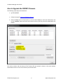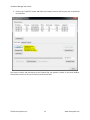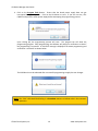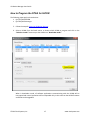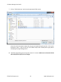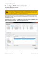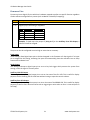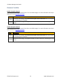
1
VSI Device Manager User Guide Document Revision 1.3 (Updated July 07, 2015) © 2015 Vital Systems Inc Phoenix, AZ USA VSI Device Manager User Guide Contents License Agreement........................................................................................................................................ 2 Introduction .................................................................................................................................................. 3 Scanning for VSI Motion Devices on the Network .................................................................................... 4 How to Upgrade the DSPMC Firmware .................................................................................................... 6 How to Program the FPGA for DSPMC...................................................................................................... 8 How to Configure DSPMC Firmware Parameters ................................................................................... 10 Firmware Pins ..................................................................................................................................... 11 Firmware Variables ............................................................................................................................. 12 How to Upgrade the HiCON Firmware.................................................................................................... 13 How to Program the FPGA for HiCON ..................................................................................................... 17 How Configure HiCON Firmware Parameters ......................................................................................... 20 Firmware Pins ..................................................................................................................................... 21 Firmware Variables ............................................................................................................................. 22 How to Activate a Feature ...................................................................................................................... 23 How to Change the Default IP Address ................................................................................................... 27 How to Enable Standalone Mode ........................................................................................................... 29 © 2015 Vital Systems, Inc. 1 www.vitalsystem.com VSI Device Manager User Guide License Agreement Before using any Vital System Motion Controller and accompanying software tools, please take a moment to go thru this License agreement. Any use of this hardware and software indicate your acceptance to this agreement. It is the nature of all machine tools that they are dangerous devices. In order to be permitted to use any Vital System Motion Controller on any machine you must agree to the following license: I agree that no-one other than the owner of this machine, will, under any circumstances be responsible, for the operation, safety, and use of this machine. I agree there is no situation under which I would consider Vital Systems, or any of its distributors to be responsible for any losses, damages, or other misfortunes suffered through the use of any Vital System Motion Controller and its software. I understand that Vital System Motion Controllers are very complex, and though the engineers make every effort to achieve a bug free environment, that I will hold no-one other than myself responsible for mistakes, errors, material loss, personal damages, secondary damages, faults or errors of any kind, caused by any circumstance, any bugs, or any undesired response by the board and its software while running my machine or device. I fully accept all responsibility for the operation of this machine while under the control of a Vital System Motion Controller, and for its operation by others who may use the machine. It is my responsibility to warn any others who may operate any device under the control of a Vital System Motion Controller of the limitations so imposed. I fully accept the above statements, and I will comply at all times with standard operating procedures and safety requirements pertinent to my area or country, and will endeavor to ensure the safety of all operators, as well as anyone near or in the area of my machine. WARNING: Machines in motion can be extremely dangerous! It is the responsibility of the user to design effective error handling and safety protection as part of the system. VITAL Systems shall not be liable or responsible for any incidental or consequential damages. By using the HICON motion controller, you agree to the license agreement. © 2015 Vital Systems, Inc. 2 www.vitalsystem.com VSI Device Manager User Guide Introduction The VSI Device Manager application for VSI Motion Controllers, is mainly used to re-program (Flash) the board software (Firmware), re-program the FPGA, optionally set the device IP, configure firmware parameters, and to enable standalone mode if necessary. Supported Devices: (pn7752) HiCON OEM (pn7766) HiCON Integra (pn7762) DSPMC The latest Firmware and FPGA files are available from their corresponding product webpages on the Vital System Inc. website. Files are downloaded in compressed zip format packages, so unzipping the required files is necessary before programming. The application can be downloaded from here. NOTE: Before programming the Firmware, close all programs (e.g. Mach3, Mach4, or any custom software application) that are communicating with your VSI Motion Controller. This includes programs running on other computers that are connected to the VSI Motion Controller over Ethernet (Local Area Network). Also make sure that the Drives are powered down. © 2015 Vital Systems, Inc. 3 www.vitalsystem.com VSI Device Manager User Guide Scanning for VSI Motion Devices on the Network The following steps describe the procedure to upgrade the firmware of the DSPMC Motion Controller (pn7762). 1. Open the “VSI Device Manager application. The following window appears: © 2015 Vital Systems, Inc. 4 www.vitalsystem.com VSI Device Manager User Guide 2. Click on the “Scan Network” button to setup the connection. All VSI Motion Controllers (HiCONs or DSPMCs) on the network will be detected and listed. NOTE: The desired VSI Motion Controller can be identified by the part number listed in the “Hardware” field. (7752) HiCON OEM (7766) HiCON Integra (7762) DSPMC If the device cannot be found, please refer to “Network Connection Setup” section in the device’s user manual to setup network communication with the device. NOTE: On some machines, it may be required to run the VSI Device Manager Application with administrator privileges (issues with scanning and the GUI not working correctly). In rare cases, the windows firewall may also need to be disabled as it can interrupt network communication with the device. © 2015 Vital Systems, Inc. 5 www.vitalsystem.com VSI Device Manager User Guide How to Upgrade the DSPMC Firmware The following steps apply to these devices (pn7762) DSPMC 1. Follow the steps for Scanning VSI Motion Devices. 2. Select a DSPMC from the listed entries to choose which DSPMC to work with. Afterwards, click on the “Load File” button and select the firmware version (.bin file) you wish to download to the DSPMC. The version number and time-stamp of the firmware file you opened is shown on the main window. Please make sure this is the correct version you intend to flash. © 2015 Vital Systems, Inc. 6 www.vitalsystem.com VSI Device Manager User Guide 3. Click on the Program Flash Button. Ensure that the board power supply does not get interrupted during this process. Click on the OK button to start. If you are not sure, click CANCEL and provide a stable power supply before attempting the programming process. NOTE: Should any programming error occur during the programming process, DO NOT reboot the unit or cycle the power. Reattempt the programming process instead and contact your vendor if repeated attempts still produce errors. Upon clicking OK, the programming process will start. The progress bar will show the programming progress. After programming, the software will perform a verification to check if the programming is successful. A ‘SUCCESS’ message is displayed if firmware programming and verification is successful as shown below. The DSPMC unit must be rebooted after a successful programming to apply the new changes. © 2015 Vital Systems, Inc. 7 www.vitalsystem.com VSI Device Manager User Guide How to Program the FPGA for DSPMC The following steps apply to these devices (pn7762) DSPMC CAUTION: Please follow these instructions carefully if upgrading the DSPMC FPGA because a missed or wrong action could, in some rare cases, brick your unit. Bricked units will have to be shipped back to Vital Systems Inc. for reprogramming and testing. 1. Follow the steps for Scanning VSI Motion Devices. 2. Select a DSPMC from the listed entries to choose which DSPMC to work with. Afterwards, click on the “FPGA Slow Prog” button and select the FPGA file (.fpga) you wish to download to the DSPMC. Ensure that the board power supply does not get interrupted during this process. Click on the OK button to start. If you are not sure, click CANCEL and provide a stable power supply before attempting the programming process. © 2015 Vital Systems, Inc. 8 www.vitalsystem.com VSI Device Manager User Guide 3. The FPGA programming process may take around 3- 5 minutes. The DSPMC CPU LED will blink rapidly for the programming process. Wait for the process to finish (the CPU LED should be in slow blink indicating that it is currently in normal operation mode). 4. Make sure to reboot the DSPMC when prompted to apply the new changes. NOTE: Should any programming error occur during the programming process, DO NOT reboot the unit or cycle the power. Reattempt the programming process instead and contact your vendor if repeated attempts still produce errors. © 2015 Vital Systems, Inc. 9 www.vitalsystem.com VSI Device Manager User Guide How to Configure DSPMC Firmware Parameters The following steps apply to these devices (pn7762) DSPMC NOTE: These settings are configured in-factory based on order specifications, and as such are not required to be configured. If configuring these parameters becomes absolutely necessary, please contact your vendor or Vital System Inc. for questions and assistance. Firmware parameters are settings that are configured directly on the DSPMC firmware. These settings affect the device’s behavior, particularly behavior on a hardware basis (e.g. pin layout changes, hardmapped input signals, etc.). These changes can be accessed on the DSPMC Tab as shown below. Clicking the Download button applies the changes to the firmware, otherwise the changes are not saved. © 2015 Vital Systems, Inc. 10 www.vitalsystem.com VSI Device Manager User Guide Firmware Pins Firmware pins are digital I/O which are hardware-mapped to perform a specific function regardless of what software configuration is present (such as Mach3 or Mach4 I/O mapping). Value -1 0 - 63 Description Disable the setting Digital I/O pin the setting is mapped to Port P11 P12 P13 P14 Input pins 0 – 15 16 – 31 32 – 47 48 – 63 Output pins 0–7 8 – 15 16 – 23 24 – 31 Example: To hard-map (P14, pin 7) as the Auxilliary Error LED Output, a value of 31 will be assigned. The pins can also be configured as active-high or active-low as necessary. Estop Inputs These settings allow Digital Input pins to be hard-mapped in the firmware as E-Stop signals. If an input pin is assigned to this setting, activating the input will automatically place the controller into an Estop state on the hardware level. Keylock Input This setting hard-maps a digital input pin to act as a key lock trigger which prevents the system from arming, unless the signal is currently active. Auxilliary CPU LED Output This setting hard-maps a digital output pin to mirror the state of the CPU LED. This is useful for display purposes such as showing the CPU LED state without having to open the controls cabinet. Auxilliary Error LED Output This setting hard-maps a digital output pin to mirror the state of the ERROR LED. This is useful for display purposes, as well as more functional ones such as triggering an action when an Error is incurred (such as an Estop). © 2015 Vital Systems, Inc. 11 www.vitalsystem.com VSI Device Manager User Guide Firmware Variables ADC Sample Count This setting controls how many sample readings (on a millisecond basis) are averaged with the Analog Input Channels. Higher values mean less fluctuations in the analog input readings while lower values make the readings more responsive Enable J11 StepGen and Encoder This setting controls the pin layout of port J11 on the DSPMC Integra. For more information see the pin layouts for J11 in the pn7762 User Guide. Value Description Enabled Used when connecting a “7737 Differential Step/Dir and Encoder board”. See J11 pin layout for connecting the 7737 board. Disabled Used when connecting a “7535 Digital I/O board”. See J11 pin layout for connecting the 7535 board. Enable J12 StepGen and Encoder This setting controls the pin layout of port J12 on the DSPMC Integra. For more information see the pin layouts for J12 in the pn7762 User Guide. Value Description Enabled Used when connecting a “7737 Differential Step/Dir and Encoder board”. See J12 pin layout for connecting the 7737 board. Disabled Used when connecting a “7535 Digital I/O board”. See J12 pin layout for connecting the 7535 board. Enable J3 Differential Step/Dir This setting changes the Step/Dir channels on J3 to either 3 Differential Step/Dir channels or 6 SingleEnded channels. For more information, see the pin layouts for J3 in the pn7762 User Guide. © 2015 Vital Systems, Inc. 12 www.vitalsystem.com VSI Device Manager User Guide How to Upgrade the HiCON Firmware The following steps apply to these devices (pn7752) HiCON OEM (pn7766) HiCON Integra 1. Follow the steps for Scanning VSI Motion Devices. 2. Select a HiCON from the listed entries to choose which HiCON to program and click on the “Switch to Loader” button to put the HiCON into “Bootloader mode”. When in bootloader mode, all software applications communicating with the HiCON will be interrupted and normal operations will be suspended. Only in this state can the HiCON firmware and FPGA can be upgraded. © 2015 Vital Systems, Inc. 13 www.vitalsystem.com VSI Device Manager User Guide NOTE: The HiCON “CPU” LED should be blinking rapidly to indicate that it is in Bootloader mode. © 2015 Vital Systems, Inc. 14 www.vitalsystem.com VSI Device Manager User Guide 3. Click on the “Load File” button and select the firmware version (.bin file) you wish to download to the HiCON. The version number and time-stamp of the firmware file you opened is shown on the main window. Please make sure this is the correct version you intend to flash. © 2015 Vital Systems, Inc. 15 www.vitalsystem.com VSI Device Manager User Guide 4. Click on the Program Flash Button. Ensure that the board power supply does not get interrupted during this process. Click on the OK button to start. If you are not sure, click CANCEL and provide a stable power supply before attempting the programming process. Upon clicking OK, the programming process will start. The progress bar will show the programming progress. After programming, the software will perform a verification to check if the programming is successful. A ‘SUCCESS’ message is displayed if firmware programming and verification is successful as shown below. The HiCON unit must be rebooted after a successful programming to apply the new changes. NOTE: The “CPU” LED should be blinking in a heartbeat manner to indicate that it has resumed normal operation. © 2015 Vital Systems, Inc. 16 www.vitalsystem.com VSI Device Manager User Guide How to Program the FPGA for HiCON The following steps apply to these devices: (pn7752) HiCON OEM (pn7766) HiCON Integra 5. Follow the steps for Scanning VSI Motion Devices. 6. Select a HiCON from the listed entries to choose which HiCON to program and click on the “Switch to Loader” button to put the HiCON into “Bootloader mode”. When in bootloader mode, all software applications communicating with the HiCON will be interrupted and normal operations will be suspended. Only in this state can the HiCON firmware and FPGA can be upgraded. © 2015 Vital Systems, Inc. 17 www.vitalsystem.com VSI Device Manager User Guide NOTE: The HiCON “CPU” LED should be blinking rapidly to indicate that it is in Bootloader mode. © 2015 Vital Systems, Inc. 18 www.vitalsystem.com VSI Device Manager User Guide 7. Click on “FPGA Slow Prog”, and select the appropriate FPGA version. Ensure that the board power supply does not get interrupted during this process. Click on the OK button to start. If you are not sure, click CANCEL and provide a stable power supply before attempting the programming process. 8. The FPGA programming process may take around 3- 5 minutes. Make sure to reboot the HiCON when prompted to apply the new changes. © 2015 Vital Systems, Inc. 19 www.vitalsystem.com VSI Device Manager User Guide How Configure HiCON Firmware Parameters The following steps apply to these devices: (pn7766) HiCON Integra NOTE: These settings are configured in-factory based on order specifications, and as such are not required to be configured. If configuring these parameters becomes absolutely necessary, please contact your vendor or Vital System Inc. for questions and assistance. Firmware parameters are settings that are configured directly on the HiCON firmware. These settings affect the device’s behavior, particularly behavior on a hardware basis (e.g. pin layout changes, hardmapped input signals, etc.). These changes can be accessed on the HiCON Tab as shown below. Clicking the Download button applies the changes to the firmware, otherwise the changes are not saved. © 2015 Vital Systems, Inc. 20 www.vitalsystem.com VSI Device Manager User Guide Firmware Pins Firmware pins are digital I/O pins which are hardware-mapped to perform a specific function regardless of what software configuration is present (such as Mach3 or Mach4 I/O mapping). Value -1 0 - 63 Description Disable the setting Digital I/O pin the setting is mapped to Port P11 P12 P13 P14 Input pins 0 – 15 16 – 31 32 – 47 48 – 63 Output pins 0–7 8 – 15 16 – 23 24 – 31 Example: To hard-map relay output 5 (P14, pin 7) as the Auxilliary Error LED Output, a value of 31 will be assigned. The pins can also be configured as active-high or active-low as necessary. Estop Inputs These settings allow Digital Input pins to be hard-mapped in the firmware as E-Stop signals. If an input pin is assigned to this setting, activating the input will automatically place the controller into an Estop state on the hardware level. Keylock Input This setting hard-maps a digital input pin to act as a key lock trigger which prevents the system from arming, unless the signal is currently active. Auxilliary CPU LED Output This setting hard-maps a digital output pin to mirror the state of the CPU LED. This is useful for display purposes such as showing the CPU LED state without having to open the controls cabinet. Auxilliary Error LED Output This setting hard-maps a digital output pin to mirror the state of the ERROR LED. This is useful for display purposes, as well as more functional ones such as triggering an action when an Error is incurred (such as an Estop). © 2015 Vital Systems, Inc. 21 www.vitalsystem.com VSI Device Manager User Guide Firmware Variables Enable J7 Step/Dir Channels This setting controls the pin layout of port J7 on the HiCON Integra. For more information see the pin layout for J7 in the pn7766 User Guide Value Description Used when connecting a 7737 Differential Step/Dir and Encoder board. See J7 pin layout Enabled for connecting the 7737 board. Used when connecting a 7535 Digital I/O board. See J7 pin layout for connecting the 7535 Disabled board. Enable J8 Step/Dir Channels This setting controls the pin layout of port J8 on the HiCON Integra. For more information see the pin layout for J8 in the pn7766 User Guide Value Description Enabled Used when connecting a 7737 Differential Step/Dir and Encoder board. See J8 pin layout for connecting the 7737 board. Disabled Used when connecting a 7535 Digital I/O board. See J8 pin layout for connecting the 7535 board. © 2015 Vital Systems, Inc. 22 www.vitalsystem.com VSI Device Manager User Guide How to Activate a Feature The following steps apply to these devices: (pn7752) HiCON OEM (pn7766) HiCON Integra (pn7762) DSPMC NOTE: Activating features requires the corresponding Activation Key. To obtain an Activation Key, please contact your vendor, or Vital System Inc. In this example, the Extended I/O feature is being activated for the HiCON Integra. 1. Follow the steps for Scanning VSI Motion Devices. 2. Select the desired motion controller, from the entry list (in this case, HiCON Integra). 3. Click on the “Activation” tab. The currently activated features for the selected device should be displayed on the right-hand view. © 2015 Vital Systems, Inc. 23 www.vitalsystem.com VSI Device Manager User Guide 4. Select the feature to activate. © 2015 Vital Systems, Inc. 24 www.vitalsystem.com VSI Device Manager User Guide 5. Input the activation key and click on the “Activate” button. A message should be displayed if the activation was successful, and the activated feature should now be included in the list of activated features. © 2015 Vital Systems, Inc. 25 www.vitalsystem.com VSI Device Manager User Guide © 2015 Vital Systems, Inc. 26 www.vitalsystem.com VSI Device Manager User Guide How to Change the Default IP Address The following steps apply to these devices: (pn7752) HiCON OEM (pn7766) HiCON Integra (pn7762) DSPMC NOTE: The following procedure may be unnecessary if the VSI Motion Device can already communicate with the VSI Device Manager application, and other software applications such as Mach3 or Mach4. 1. Follow the steps for Scanning VSI Motion Devices. 2. Select the motion controller, from the entry list, whose IP address will be changed. 3. Type in the desired IP Address in the lower right and click “Set New IP Addr”. NOTE: DO NOT use the network adapter IP Address, otherwise connection issues due to conflicting IP addresses on the network will occur. © 2015 Vital Systems, Inc. 27 www.vitalsystem.com VSI Device Manager User Guide 4. The new address will be saved on the VSI Motion Device and will take effect after the power is cycled on the unit. WARNING: If no VSI Motion Controller is selected from the list, then the new IP Address will be assigned (via UDP Broadcast) to all VSI Motion Controllers (HiCONs or DSPMCs) on the network. In this case, it is advised to have only one VSI Motion Controller on the network. This action is only recommended if the VSI Motion Controller has an unknown IP Address that is on a different network from the PC. © 2015 Vital Systems, Inc. 28 www.vitalsystem.com VSI Device Manager User Guide How to Enable Standalone Mode Standalone mode is an optional tool that allows the HiCON to operate without PC control. In this mode, the HiCON will utilize the configuration from Mach3 or Mach4 (saved in flash) and a HiCON Basic or C Macro (programmed on the device) to perform motion and I/O control. The following steps apply to these devices: (pn7752) HiCON OEM (pn7766) HiCON Integra NOTE: Before beginning Standalone mode, make sure that a HiCON Basic/C Macro is present on the HiCON. For more information on this, see the “HiCON Basic Manual”. 1. Open Mach3 or Mach4 and configure the HiCON via the plugin config (System Config and Axis Config) and the Mach3/Mach4 config window. 2. Arm Mach3 or Mach4 to force the configuration to download. Perform simple test moves such as jogging, or test motion from the plugin config window to verify that the configuration was successfully downloaded. 3. Open the VSI Device Manager application and follow the steps for Scanning VSI Motion Devices. 4. Select the HiCON from the entry list, and click “Enable Standalone” to save the configuration into the flash memory. 5. If the downloaded HiCON Basic Macro had been set to autorun, the HiCON should be able to execute the macro on power up. © 2015 Vital Systems, Inc. 29 www.vitalsystem.com