1
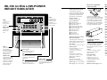
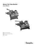
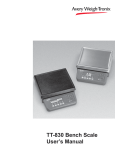
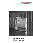
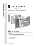
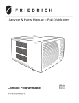
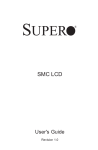
BC-150 Battery Charger
Designed to recharge the 8-volt BP-150
battery pack. The battery charger pays
for itself rapidly; its sensor system
continuously monitors the battery
voltage. Overcharging a battery greatly
reduces battery life. The BC-150 battery
charger recharges batteries quickly and
will not overcharge, even when batteries
are left “on charge” indefinitely.
Input power:
100 to 130 VAC 50/60 Hz at .25 ampere
200 to 260 VAC 50/60 Hz at .12 ampere
Circuit protection:
Fuse, 0.5 ampere at 115 VAC,
.25 ampere at 230 VAC
Charging circuit:
Two-step constant current with
remote voltage sensing
Current charge: 520 milliamperes
Weigh Bars®
for Hazardous environment installations
Weigh-Tronix has a wide
range of Weigh Bars that
have been approved by
Factory Mutual for
hazardous installations.
With approved capacities
from 30 to 200,000 pounds,
Weigh-Tronix offers more
than 80 models of Weigh
Bars for truck scales; bench
and deck scales; bin, tank
and hopper scales; and
batching applications.
•
Factory Mutual Approved
Control Document 29274
•
Legal-for-trade
Class III/IIIL 10,000 divisions
•
Stainless steel
NEMA 4X enclosure
•
1" high digits
Factory Mutual Control
Document #29274
provides a list of all approved weight sensors and
junction boxes compatible with the WI-150 Indicator.
Float current: 10.4 milliamperes
Automatic charge / float control:
When battery voltage exceeds 9.93
volts, the unit switches to
float. When
the battery voltage drops to less than
9.27 volts, the unit switches to charge.
All Weigh-Tronix products bearing the
Factory Mutual seal are designed and
manufactured according to the
guidelines set forth by Factory Mutual
Research. It is the responsibility of
Remote voltage
sensing input resistance:
300K ohms
owners to gain approval from their
insurance company for the suitability of
the Weigh-Tronix equipment and
installation for their particular
Recharge time:
14 hours typical for 90%
discharged battery.
environment.
Weigh-Tronix assumes no
responsibility or liability either
expressed or implied for the suitability
of the Weigh-Tronix equipment for the
Weigh-Tronix
1000 Armstrong Dr.
Fairmont, MN 56031 USA
Telephone: 507-238-4461
Facsimile: 507-238-4195
e-mail: [email protected]
www.wtxweb.com
Weigh-Tronix Canada, ULC
217 Brunswick Blvd.
Pointe Claire, QC H9R 4R7 Canada
Telephone: 514-695-0380
Facsimile: 514-695-6820
owners’ specific application or
environment.
Weigh Bar® is a registered trademark of Weigh-Tronix Inc
701 150_L.P65 PN 09561-0002B
Printed in USA
Weighing Products & Systems
WI-150 Ultra Low-power
Weight Indicator
Fiber-Link, single fiber
optics converter
WI-150 ULTRA LOW-POWER
WEIGHT INDICATOR
BP-150 Rechargeable
Battery Pack
PARALLEL BCD OUTPUT
CARD SPECIFICATIONS
The BP-150 Battery Pack for the WI-150
The parallel BCD output card
current-limited to an acceptable level for
provides 5-1/4 decades of data that
use in hazardous area application.
may be used to interface printers or
Weigh-Tronix recommends the PS-
programmable controllers when a
150XP or PS-150 power source when
serial interface is not desirable.
UNITS
Interface signals:
Changes the unit
HC MOS 5-volt logic levels
MENU
of measure during
Accesses menus
operations mode
and moves
and inserts a
■ Enable control line
among choices
decimal point when
■ Data change inhibit input
in a menu.
keying in values.
■ Weight data output
Input / output lines:
provides a nominal 8-volt output that is
Located in the safe area, the
Fiber-Link is a single function fiber
optic converter. Fiber-Link devices
include RS-232, RS-422, current
loop, cutoff and analog. Use up to
three Fiber-Links in an installation:
One RS-232 or RS-422 or current
loop plus analog and/or cutoff.
the WI-150 Indicator is linked with FiberLinks or the SC-150.
Battery life is a function of the battery, the
number of weight sensors, and the total
time the scale is active versus asleep.
For example:
■ Plus and minus sign output
Four 350 ohm weight sensors,
95% of time in sleep mode:
PRINT SELECT
■ Pounds and kilograms output
1870-hour battery life
Sends a print
■ Gross and net output
command and
■ Printer inhibit output
Four 350 ohm weight sensors,
50% of time in sleep mode:
selects menu
■ Valid data output
530-hour battery life.
items.
■ Motion output
Four 350 ohm weight sensors,
no sleep mode:
■ BCD print input
■ Remote print output
295-hour battery life
ANALOG OUTPUT CARD
SPECIFICATIONS
136-hour battery life
digital-to-analog converter to provide
PS-150 Power Supply
with Barrier
switch-selectable isolated outputs.
Located in the safe area of a hazardous
5.2 ampere-hours
Input power:
environment installation, the PS-150
Nominal open circuit voltage:
10 to 13 VAC, 48 to 62 Hz at 250 mA
115 / 230 VAC Power Supply with
8.0 volts
The analog output card employs a
TARE +/-
Output signals:
Enters a pushbutton
tare in gross/net
Four 350 ohm weight sensors,
no sleep mode, linked to SC-150:
DIP switch selectable , 1 to 5 mA,
Barrier provides DC output to the WI150 Indicator.
0 to 9 keypad
4 to 20 mA, 10 to 50 mA,
Output:
enters numbers and specifies
0 to +5 volts or 0 to +10 volts
13.5 volt DC, voltage and current
tare and cutoff registers.
Isolation:
OFF
Analog output is isolated via
Puts the battery-pack model
opto isolator and the low voltage
Entity parameters:
GROSS / NET
indicator into an ultra-low power
isolation power transformer
For Division 1, Class I,
Accesses the gross/net
consumption mode called the
weighing mode from any
sleep mode.
other function, and
toggles the unit between
operation. During data
entry this key toggles
between positive and
negative values.
Resolution:
limited by a Factory Mutual
approved barrier.
Groups A, B, C, D, E, F, G:
Ca equal or less than 0.4 uF
ZERO CLEAR
More than 21,845 divisions
ON
Zeros the scale in gross/net weigh
represent zero to full scale range.
Wakes the battery-pack model
gross and net weights,
mode. Also clears keyed-in digits
from sleep mode. (PS-150
Under range: -25% of full capacity
on the display before they are
ISC equals 435.4 mA
assuming there is an
powered units are always on.)
accepted.
Over range: +25% of full capacity
Maximum cable length: 900 feet
active tare weight.
La equal or less than 0.18 mH
Voc equals +18.2 V
Ampere-hour capacity:
Current limiting resistance:
16.5 ohms
Remote voltage sensing:
Provided through 1000 ohm resistor.
Enclosure:
NEMA 4, water tight stainless steel
81/2" x 3" x 3" (21.6 cm x 7.6 cm x 7.6 cm)
Features and benefits
SC-150 Serial &
Control Unit
SERIAL I/O CARD
SPECIFICATIONS
Serial I/O card provides a single serial
port, four cutoff output transistors and
two logic level inputs.
Data output:
Switch-selectable serial RS-232,
For installations in hazardous
RS-422/485 or 20 mA current loop.
environments, the WI-150 Indicator
sends data to peripheral equipment
via fiber optic cable. The SC-150 Serial
and Control Unit, located in a safe area,
converts the indicator’s digital impulses
to output that will communicate with
computers, printers, programmable
controllers and remote displays. Select
Handshaking:
Hardware ready / busy for RS-232
only. XON / XOFF for RS-232,
RS-422/485 and current loop
Baud rates:
110, 300, 600, 1200, 2400,
4800, 9600 and 19,200
the combination of cards you need to
complete your system:
Word length:
8 data bits including parity
■ One or two serial
input / output cards
Parity bit:
Even, odd, logic 1 or logic 0
■ A dual RS-232 /
RS-422 / RS-485 card
■ A cutoff and parallel
input / output card
■ A parallel BCD output card
■ An analog output card
DUAL SERIAL I/O CARD
SPECIFICATIONS
The dual serial I/O card provides two
serial ports, programmable for a
variety of signal transmission voltage
levels, baud rates, parity choices, and
CUTOFF & PARALLEL I/0
CARD SPECIFICATIONS
The cutoff & parallel I/O card
provides ten cutoff outputs, six
status outputs, and ten command
inputs. The cutoff outputs are
configurable to be entered as
individual ingredient weights or as
setpoints (total displayed weight).
Relay power:
No relay power is provided
by the SC-150
Cutoff outputs:
10 open drain MOS field effect
transistors switching to ground
Voltage: +60 volts DC max
Current: 200 mA max
On resistance: 7.5 ohms max
Inductive kick protection:
Fly back diodes on all outputs
Status outputs:
Six open drain MOS field effect
transistors switching to ground.
Status signals:
Stable, Net, Gross, Center of
zero, and Alright
custom formatting.
SC-150 SERIAL & CONTROL
UNIT SPECIFICATIONS
Data output:
Switch-selectable serial
Command inputs:
Zero, Net, Gross, Push-button tare,
Print, plus five additional inputs
Input power:
100 to 130 VAC, 48 to 62 Hz
at 100 mA 200 to 260 VAC
48 to 62 Hz at 60 mA
RS-232 or RS-422/485
Circuit protection:
Internal fuse, 1/4 amp at
115 VAC, 1/8 amp at 230 VAC
422/485 and current loop
Logic “0” voltage level:
0.0 to +1.5 volts
Baud rates:
Low level input current: -0.5 mA
Fiber optics cable length:
250 feet maximum
4800, 9600 and 19,200
Handshaking:
Logic “1” voltage level:
+3.5 to +5.0 volts
Hardware ready / busy for RS-232
only. XON / XOFF for RS-232, RS-
110, 300, 600, 1200, 2400,
Word length:
8 data bits including parity
Parity bit:
Even, odd, logic 1 or logic 0
Factory Mutual approved —
Menu driven —
The WI-150 Weight Indicator
Simplifies the operation of the WI-150.
has been tested and accepted for
Just press the MENU key and cycle
hazardous environments including
through the available function choices.
the following location classifications:
Adapt the menu to your operation
Class I (gases), Divisions I and II;
during configuration. Select only the
Groups A, B, C, and D; Class II (dusts),
options you want to appear under
Divisions I and II, Groups
MENU key.
E, F and G; and Class III (fibers),
Divisions I and II.
Security code —
Protects configuration, calibration,
Versatile —
and user data from unauthorized
The WI-150 can operate from a
tampering.
BP-150 Battery Pack, PS-150XP
continuous power source, or from a
Selectable units of measure —
PS-150 AC to DC Power Supply with
Configure the WI-150 to measure in
barrier located in a safe area. Use the
pounds, kg, or even gallons with
indicator for simple scale operations or
programmable density.
link it with computers, printers and other
data-gathering devices.
Front panel configuration—
Selectable tare operation —
Select pushbutton tare and/or up to 10
keyboard tare registers.
All calibration and programming is done
Battery saver —
Low-power A to D converter for the
battery pack version. Conserves
battery life with one-eighth duty
cycle load cell drive.
Sleep mode —
Extends battery life on battery pack
versions. Programmable for virtually
any interval of scale idleness.
Battery backed up RAM —
Protects tare and pushbutton
zero information. EEPROM stores
configuration and calibration data.
Options
Fiber optics data interface card —
Installs in the WI-150 Indicator to
facilitate transmission of signals
through a fiber optics cable to
receiving circuitry in a safe area.
Includes time and date.
through the front panel.
WI-150 Specifications
Enclosure:
NEMA 4X, water-tight, stainless
steel 73/4" high x 91/8" wide x 6"
deep (19.6 cm x 23.2 cm x 15.2
cm)
Display rate:
Zero:
±0.66 uV/°C (-10 to 40°C)
Display:
7-segment LCD, 8 digits, 1.0-inch
high with 10 annunciators
Span:
±10 ppm/°C
Zero:
±0.13 uV/°C (-30 to 60°C)
Capacities:
Programmable to any number
between .00001 and 999,999
±0.005% of capacity, maximum
Hazardous location classifications: Class I, Divisions I and II,
Groups A, B, C, and D;
Class II, Divisions I and II,
Groups E, F, and G
Class III, Divisions I and II
Entity parameters:
Vmax = 19 V, Imax = 450 mA,
Ci - 0.24 uF, Li - 0 mH
Selectable to 1, 2, or 5 /second
Accuracy:
Span:
±5.0 ppm/°C
Linearity:
Controls:
MENU
TARE
UNITS
ON
PRINT / SELECT
GROSS / NET
ZERO / CLEAR
OFF
Annunciators:
Gross
Tare
Low Bat
Motion
gal
lb
Zero
Net
Print
kg
Repeatability:
Excitation:
Drives up to eight 350-ohm
Hysteresis: 0.005% of capacity, Maximum Weigh Bars or twenty-two
1000-ohm Weigh Bars
±0.005% of capacity, maximum
Voltage requirements:
+5.6 to 13.5 volts DC
Resolution:
Environment:
-10 to 40°C (14 to 104°F)
10 to 90% relative humidity
Sealable to 10,000 divisions.
Higher resolutions available
Increments:
Programmable to any size
between .00001 and 20,000 lb / kg
Shipping weight: 14 lb (6.4 kg)
Fiber Optic Cable
HAZARDOUS AREA
Fiber optics cables carry scale
information from the WI-150 Indicator
to either the SC-150 Control Unit or
the Fiber-Link signal converters located
in the safe area. The cable has a dual layer
of protection. The outside polyethylene jacket
protects cable from moisture, cracking and
surface nicks. An inner Kevlar strength
member surrounds the fibers, giving the
cable the rigidity to keep fibers
from being damaged by
overbending.
The AC-powered WI-150 Indicator and an
approved weighing device are located within the
hazardous area.
Factory Mutual Control Document 29274
provides a list of all weight sensors and junction
boxes that Factory Mutual has approved for
operation as a system with the WI-150 in
hazardous environments.
The SC-150 Serial and
Computer
Control Unit, located in a safe
area, receives data from the
WI-150 via fiber optic cable and
Printer
converts the signal to be used by
peripheral equipment. Can have up to
six cards. Select for present needs and
still have room for expanding the system.
Other
■ One or two single-port, switch-selectable
serial RS-232, RS-422-485, 20 mA current loop
input / output cards
■ Dual RS-232 / RS-422 / RS-485 card
■ Cutoff and parallel input / output card
■ Parallel BCD output card
For operation with peripheral equipment, the WI-150
must include the optional fiber optics interface card.
Scale
Power Cable
■ Analog output card.
Fiber-Link,
located in the
safe area, is a
single-function fiber
optic converter.
Fiber-Link devices
include RS-232, RS-422,
current loop, cutoff and
analog. Power to this circuitry
may be supplied from some
peripheral instruments or from a
wall-mount transformer.
PS-150 Power Supply, located in
the safe area, provides 13.5 volt DC
HAZARDOUS AREA
continuous output to the WI-150
Indicator. Voltage and current are
limited by the PS-150's Factory
Mutual approved barrier.
The battery-powered WI-150 Indicator,
its BP-150 Battery Pack, and approved
weighing device are located in the
hazardous area. The battery-powered
WI-150 has a special low-power A to D
converter with a one-eighth duty cycle load
cell drive to conserve battery life.
The battery pack provides a nominal 8-volt
output, current limited to an acceptable
output for operation in hazardous areas.
Scale
BC-150 Battery Charger operates in the
safe area. Its sensor system continuously
monitors battery voltage during recharging
to prevent over-charging and shortened
battery life.
Features and benefits
SC-150 Serial &
Control Unit
SERIAL I/O CARD
SPECIFICATIONS
Serial I/O card provides a single serial
port, four cutoff output transistors and
two logic level inputs.
Data output:
Switch-selectable serial RS-232,
For installations in hazardous
RS-422/485 or 20 mA current loop.
environments, the WI-150 Indicator
sends data to peripheral equipment
via fiber optic cable. The SC-150 Serial
and Control Unit, located in a safe area,
converts the indicator’s digital impulses
to output that will communicate with
computers, printers, programmable
controllers and remote displays. Select
Handshaking:
Hardware ready / busy for RS-232
only. XON / XOFF for RS-232,
RS-422/485 and current loop
Baud rates:
110, 300, 600, 1200, 2400,
4800, 9600 and 19,200
the combination of cards you need to
complete your system:
Word length:
8 data bits including parity
■ One or two serial
input / output cards
Parity bit:
Even, odd, logic 1 or logic 0
■ A dual RS-232 /
RS-422 / RS-485 card
■ A cutoff and parallel
input / output card
■ A parallel BCD output card
■ An analog output card
DUAL SERIAL I/O CARD
SPECIFICATIONS
The dual serial I/O card provides two
serial ports, programmable for a
variety of signal transmission voltage
levels, baud rates, parity choices, and
CUTOFF & PARALLEL I/0
CARD SPECIFICATIONS
The cutoff & parallel I/O card
provides ten cutoff outputs, six
status outputs, and ten command
inputs. The cutoff outputs are
configurable to be entered as
individual ingredient weights or as
setpoints (total displayed weight).
Relay power:
No relay power is provided
by the SC-150
Cutoff outputs:
10 open drain MOS field effect
transistors switching to ground
Voltage: +60 volts DC max
Current: 200 mA max
On resistance: 7.5 ohms max
Inductive kick protection:
Fly back diodes on all outputs
Status outputs:
Six open drain MOS field effect
transistors switching to ground.
Status signals:
Stable, Net, Gross, Center of
zero, and Alright
custom formatting.
SC-150 SERIAL & CONTROL
UNIT SPECIFICATIONS
Data output:
Switch-selectable serial
Command inputs:
Zero, Net, Gross, Push-button tare,
Print, plus five additional inputs
Input power:
100 to 130 VAC, 48 to 62 Hz
at 100 mA 200 to 260 VAC
48 to 62 Hz at 60 mA
RS-232 or RS-422/485
Circuit protection:
Internal fuse, 1/4 amp at
115 VAC, 1/8 amp at 230 VAC
422/485 and current loop
Logic “0” voltage level:
0.0 to +1.5 volts
Baud rates:
Low level input current: -0.5 mA
Fiber optics cable length:
250 feet maximum
4800, 9600 and 19,200
Handshaking:
Logic “1” voltage level:
+3.5 to +5.0 volts
Hardware ready / busy for RS-232
only. XON / XOFF for RS-232, RS-
110, 300, 600, 1200, 2400,
Word length:
8 data bits including parity
Parity bit:
Even, odd, logic 1 or logic 0
Factory Mutual approved —
Menu driven —
The WI-150 Weight Indicator
Simplifies the operation of the WI-150.
has been tested and accepted for
Just press the MENU key and cycle
hazardous environments including
through the available function choices.
the following location classifications:
Adapt the menu to your operation
Class I (gases), Divisions I and II;
during configuration. Select only the
Groups A, B, C, and D; Class II (dusts),
options you want to appear under
Divisions I and II, Groups
MENU key.
E, F and G; and Class III (fibers),
Divisions I and II.
Security code —
Protects configuration, calibration,
Versatile —
and user data from unauthorized
The WI-150 can operate from a
tampering.
BP-150 Battery Pack, PS-150XP
continuous power source, or from a
Selectable units of measure —
PS-150 AC to DC Power Supply with
Configure the WI-150 to measure in
barrier located in a safe area. Use the
pounds, kg, or even gallons with
indicator for simple scale operations or
programmable density.
link it with computers, printers and other
data-gathering devices.
Front panel configuration—
Selectable tare operation —
Select pushbutton tare and/or up to 10
keyboard tare registers.
All calibration and programming is done
Battery saver —
Low-power A to D converter for the
battery pack version. Conserves
battery life with one-eighth duty
cycle load cell drive.
Sleep mode —
Extends battery life on battery pack
versions. Programmable for virtually
any interval of scale idleness.
Battery backed up RAM —
Protects tare and pushbutton
zero information. EEPROM stores
configuration and calibration data.
Options
Fiber optics data interface card —
Installs in the WI-150 Indicator to
facilitate transmission of signals
through a fiber optics cable to
receiving circuitry in a safe area.
Includes time and date.
through the front panel.
WI-150 Specifications
Enclosure:
NEMA 4X, water-tight, stainless
steel 73/4" high x 91/8" wide x 6"
deep (19.6 cm x 23.2 cm x 15.2
cm)
Display rate:
Zero:
±0.66 uV/°C (-10 to 40°C)
Display:
7-segment LCD, 8 digits, 1.0-inch
high with 10 annunciators
Span:
±10 ppm/°C
Zero:
±0.13 uV/°C (-30 to 60°C)
Capacities:
Programmable to any number
between .00001 and 999,999
±0.005% of capacity, maximum
Hazardous location classifications: Class I, Divisions I and II,
Groups A, B, C, and D;
Class II, Divisions I and II,
Groups E, F, and G
Class III, Divisions I and II
Entity parameters:
Vmax = 19 V, Imax = 450 mA,
Ci - 0.24 uF, Li - 0 mH
Selectable to 1, 2, or 5 /second
Accuracy:
Span:
±5.0 ppm/°C
Linearity:
Controls:
MENU
TARE
UNITS
ON
PRINT / SELECT
GROSS / NET
ZERO / CLEAR
OFF
Annunciators:
Gross
Tare
Low Bat
Motion
gal
lb
Zero
Net
Print
kg
Repeatability:
Excitation:
Drives up to eight 350-ohm
Hysteresis: 0.005% of capacity, Maximum Weigh Bars or twenty-two
1000-ohm Weigh Bars
±0.005% of capacity, maximum
Voltage requirements:
+5.6 to 13.5 volts DC
Resolution:
Environment:
-10 to 40°C (14 to 104°F)
10 to 90% relative humidity
Sealable to 10,000 divisions.
Higher resolutions available
Increments:
Programmable to any size
between .00001 and 20,000 lb / kg
Shipping weight: 14 lb (6.4 kg)
Fiber-Link, single fiber
optics converter
WI-150 ULTRA LOW-POWER
WEIGHT INDICATOR
BP-150 Rechargeable
Battery Pack
PARALLEL BCD OUTPUT
CARD SPECIFICATIONS
The BP-150 Battery Pack for the WI-150
The parallel BCD output card
current-limited to an acceptable level for
provides 5-1/4 decades of data that
use in hazardous area application.
may be used to interface printers or
Weigh-Tronix recommends the PS-
programmable controllers when a
150XP or PS-150 power source when
serial interface is not desirable.
UNITS
Interface signals:
Changes the unit
HC MOS 5-volt logic levels
MENU
of measure during
Accesses menus
operations mode
and moves
and inserts a
■ Enable control line
among choices
decimal point when
■ Data change inhibit input
in a menu.
keying in values.
■ Weight data output
Input / output lines:
provides a nominal 8-volt output that is
Located in the safe area, the
Fiber-Link is a single function fiber
optic converter. Fiber-Link devices
include RS-232, RS-422, current
loop, cutoff and analog. Use up to
three Fiber-Links in an installation:
One RS-232 or RS-422 or current
loop plus analog and/or cutoff.
the WI-150 Indicator is linked with FiberLinks or the SC-150.
Battery life is a function of the battery, the
number of weight sensors, and the total
time the scale is active versus asleep.
For example:
■ Plus and minus sign output
Four 350 ohm weight sensors,
95% of time in sleep mode:
PRINT SELECT
■ Pounds and kilograms output
1870-hour battery life
Sends a print
■ Gross and net output
command and
■ Printer inhibit output
Four 350 ohm weight sensors,
50% of time in sleep mode:
selects menu
■ Valid data output
530-hour battery life.
items.
■ Motion output
Four 350 ohm weight sensors,
no sleep mode:
■ BCD print input
■ Remote print output
295-hour battery life
ANALOG OUTPUT CARD
SPECIFICATIONS
136-hour battery life
digital-to-analog converter to provide
PS-150 Power Supply
with Barrier
switch-selectable isolated outputs.
Located in the safe area of a hazardous
5.2 ampere-hours
Input power:
environment installation, the PS-150
Nominal open circuit voltage:
10 to 13 VAC, 48 to 62 Hz at 250 mA
115 / 230 VAC Power Supply with
8.0 volts
The analog output card employs a
TARE +/-
Output signals:
Enters a pushbutton
tare in gross/net
Four 350 ohm weight sensors,
no sleep mode, linked to SC-150:
DIP switch selectable , 1 to 5 mA,
Barrier provides DC output to the WI150 Indicator.
0 to 9 keypad
4 to 20 mA, 10 to 50 mA,
Output:
enters numbers and specifies
0 to +5 volts or 0 to +10 volts
13.5 volt DC, voltage and current
tare and cutoff registers.
Isolation:
OFF
Analog output is isolated via
Puts the battery-pack model
opto isolator and the low voltage
Entity parameters:
GROSS / NET
indicator into an ultra-low power
isolation power transformer
For Division 1, Class I,
Accesses the gross/net
consumption mode called the
weighing mode from any
sleep mode.
other function, and
toggles the unit between
operation. During data
entry this key toggles
between positive and
negative values.
Resolution:
limited by a Factory Mutual
approved barrier.
Groups A, B, C, D, E, F, G:
Ca equal or less than 0.4 uF
ZERO CLEAR
More than 21,845 divisions
ON
Zeros the scale in gross/net weigh
represent zero to full scale range.
Wakes the battery-pack model
gross and net weights,
mode. Also clears keyed-in digits
from sleep mode. (PS-150
Under range: -25% of full capacity
on the display before they are
ISC equals 435.4 mA
assuming there is an
powered units are always on.)
accepted.
Over range: +25% of full capacity
Maximum cable length: 900 feet
active tare weight.
La equal or less than 0.18 mH
Voc equals +18.2 V
Ampere-hour capacity:
Current limiting resistance:
16.5 ohms
Remote voltage sensing:
Provided through 1000 ohm resistor.
Enclosure:
NEMA 4, water tight stainless steel
81/2" x 3" x 3" (21.6 cm x 7.6 cm x 7.6 cm)
BC-150 Battery Charger
Designed to recharge the 8-volt BP-150
battery pack. The battery charger pays
for itself rapidly; its sensor system
continuously monitors the battery
voltage. Overcharging a battery greatly
reduces battery life. The BC-150 battery
charger recharges batteries quickly and
will not overcharge, even when batteries
are left “on charge” indefinitely.
Input power:
100 to 130 VAC 50/60 Hz at .25 ampere
200 to 260 VAC 50/60 Hz at .12 ampere
Circuit protection:
Fuse, 0.5 ampere at 115 VAC,
.25 ampere at 230 VAC
Charging circuit:
Two-step constant current with
remote voltage sensing
Current charge: 520 milliamperes
Weigh Bars®
for Hazardous environment installations
Weigh-Tronix has a wide
range of Weigh Bars that
have been approved by
Factory Mutual for
hazardous installations.
With approved capacities
from 30 to 200,000 pounds,
Weigh-Tronix offers more
than 80 models of Weigh
Bars for truck scales; bench
and deck scales; bin, tank
and hopper scales; and
batching applications.
•
Factory Mutual Approved
Control Document 29274
•
Legal-for-trade
Class III/IIIL 10,000 divisions
•
Stainless steel
NEMA 4X enclosure
•
1" high digits
Factory Mutual Control
Document #29274
provides a list of all approved weight sensors and
junction boxes compatible with the WI-150 Indicator.
Float current: 10.4 milliamperes
Automatic charge / float control:
When battery voltage exceeds 9.93
volts, the unit switches to
float. When
the battery voltage drops to less than
9.27 volts, the unit switches to charge.
All Weigh-Tronix products bearing the
Factory Mutual seal are designed and
manufactured according to the
guidelines set forth by Factory Mutual
Research. It is the responsibility of
Remote voltage
sensing input resistance:
300K ohms
owners to gain approval from their
insurance company for the suitability of
the Weigh-Tronix equipment and
installation for their particular
Recharge time:
14 hours typical for 90%
discharged battery.
environment.
Weigh-Tronix assumes no
responsibility or liability either
expressed or implied for the suitability
of the Weigh-Tronix equipment for the
Weigh-Tronix
1000 Armstrong Dr.
Fairmont, MN 56031 USA
Telephone: 507-238-4461
Facsimile: 507-238-4195
e-mail: [email protected]
www.wtxweb.com
Weigh-Tronix Canada, ULC
217 Brunswick Blvd.
Pointe Claire, QC H9R 4R7 Canada
Telephone: 514-695-0380
Facsimile: 514-695-6820
owners’ specific application or
environment.
Weigh Bar® is a registered trademark of Weigh-Tronix Inc
701 150_L.P65 PN 09561-0002B
Printed in USA
Weighing Products & Systems
WI-150 Ultra Low-power
Weight Indicator
The PS-150 XP can
be installed in the
hazardous areas and
will supply the WI-150
indicator with safe,
continuous DC power.
The unit is Factory
Mutual approved for
Class I, II, III, Division 1,
Groups B, C, D, E, F, G.
PS-150 XP
Explosion Proof Power Supply for the WI-150
The PS-150 XP receives 115 or 230 VAC via a rigid metal conduit. This PS-150 XP power supply is
Factory Mutual approved for Class I, Division I, Groups B, C, D; Class II, Division I, Groups E, F, G and
Class III, Division I locations. The PS-150 XP can be installed in these hazardous areas and will
supply the WI-150 indicator with continuous DC power. Continuous power eliminates battery hassles
and is beneficial for communications with on-line peripheral options.
All Weigh-Tronix products bearing the Factory Mutual seal are designed and manufactured accoring to the guidelines set forth by
factory Mutual Research.
It is the responsibility of owners to gain approval from their insurance company for the suitabilty of the Weigh-tronix equipment and
instalation for their particular environments.
Weigh-Tronix assumes no responsibiity or liability, either expressed or implied, for the suitability of the Weigh-tronix equipment
for the owners specific applicatin or environment.
Weigh-Tronix
1000 Armstrong Dr.
Fairmont, MN 56031 USA
Telephone: 507-238-4461
Facsimile: 507-238-4195
e-mail: [email protected]
www.weigh-tronix.com
Weigh-Tronix Canada, ULC
217 Brunswick Blvd.
Pointe Claire, QC H9R 4R7 Canada
Telephone: 514-695-0380
Facsimile: 514-695-6820
Weighing Products & Systems
4/99 PS150XP.P65 PN 09710-0002 Printed in USA