1
Clipsal Schedule Plus Building
Management Software for C-Bus
Schedule Plus
Programmer's
Guide
Version 3.1
© Copyright 2000-2005 Clipsal Integrated Systems Pty Ltd
Schedule Plus
Copyright Notice
© Copyright 2000-2005 Clipsal Integrated Systems Pty Ltd. All rights reserved
Trademarks
Clipsal is a registered trademark of Clipsal Australia Pty Ltd.
C-Bus is a registered trademark of Clipsal Integrated Systems Pty Ltd
Schedule Plus is a registered trademark of Clipsal Integrated Systems Pty Ltd
Intelligent Building Series is a registered trademark of Clipsal Integrated Systems Pty Ltd
Windows is a trademark of Microsoft Corporation
All other logos and trademarks are the property of their respective owners
Disclaimer
Clipsal Integrated Systems reserves the right to change specifications or designs
described in this manual without notice and without obligation.
Schedule Plus Programmer's Guide
Intelligent Building Series
Table of Contents
Section
Page
1
Product Range
......................................................................................... 3
2
Description
......................................................................................... 4
3
Menu Notation
......................................................................................... 5
4
Definitions
......................................................................................... 6
5
C-Bus Concepts
......................................................................................... 7
5.1
5.2
5.3
5.4
5.5
5.6
5.7
5.8
5.9
About C-Bus
................................................................................................................ 7
Networks ................................................................................................................ 7
Applications
................................................................................................................ 10
Group Addresses
................................................................................................................ 10
Levels
................................................................................................................ 10
Percentage................................................................................................................ 11
Ramp Rates
................................................................................................................ 11
C-Bus Tags
................................................................................................................ 12
Hexadecimal
................................................................................................................
Numbers
12
.........................................................................................
14
Configuring the Schedule
Plus Software
6
6.1
6.2
6.3
6.4
6.5
6.6
6.7
Starting the
................................................................................................................
Software
14
Software Screen
................................................................................................................ 14
Program Options
................................................................................................................ 15
Operation ................................................................................................................
Mode
17
Internet Access
................................................................................................................ 17
Command................................................................................................................
Line Parameters
18
Creating a................................................................................................................
Desktop Shortcut
19
.........................................................................................
20
Using the Schedule Plus
Software
7
7.1
7.2
7.3
7.4
7.5
7.6
7.7
7.8
7.9
7.10
7.11
7.12
7.13
7.14
7.15
7.16
Tool Bars ................................................................................................................ 20
Keyboard Shortcuts
................................................................................................................ 22
Step by Step
................................................................................................................
Guide
23
Creating and
................................................................................................................
Saving Projects
23
Pages
................................................................................................................ 39
Components
................................................................................................................ 41
Themes ................................................................................................................ 73
Scenes ................................................................................................................ 75
Schedules................................................................................................................ 79
Access Control
................................................................................................................ 93
Special Days
................................................................................................................ 98
Irrigation................................................................................................................ 101
Alarms ................................................................................................................ 107
Testing, Debugging
................................................................................................................
and Operation
107
Schedule................................................................................................................
Plus Designs
115
C-Gate ................................................................................................................ 118
© Copyright 2000-2005 Clipsal Integrated Systems Pty Ltd
Page 1
Schedule Plus Programmer's Guide
Intelligent Building Series
......................................................................................... 120
8
Menu Items
9
Other Help Sources......................................................................................... 123
9.1
9.2
9.3
9.4
9.5
10
10.1
10.2
10.3
10.4
10.5
11
11.1
11.2
11.3
11.4
11.5
11.6
11.7
12
Help File ................................................................................................................ 123
FAQ
................................................................................................................ 123
Tip of the................................................................................................................
Day
123
Whats New
................................................................................................................ 123
CIS Web Site
................................................................................................................ 123
......................................................................................... 124
Documenting the Installation
Story Board
................................................................................................................
Pro-Forma
125
Scene Pro-Forma
................................................................................................................ 126
Schedule................................................................................................................
Pro-Forma
126
Saving the
................................................................................................................
Screen Images
127
User Manual
................................................................................................................ 128
Tutorial
......................................................................................... 129
Before Starting
................................................................................................................ 129
Creating a
................................................................................................................
Personal Template
129
Tutorial Project
................................................................................................................ 130
Story Board
................................................................................................................ 131
Pages ................................................................................................................ 133
Adding Scenes
................................................................................................................ 134
Adding Schedules
................................................................................................................ 136
Error Messages
......................................................................................... 137
12.1
12.2
12.3
12.4
Purpose ................................................................................................................ 137
Suppressing
................................................................................................................
Error Messages
137
Reporting................................................................................................................
Errors
137
Message ................................................................................................................
List
138
Index
178
© Copyright 2000-2005 Clipsal Integrated Systems Pty Ltd
Page 2
Intelligent Building Series
1
Schedule Plus Programmer's Guide
Product Range
The products included in this range are:
5000SP
Schedule Plus, Single Network Licence
5000SP5
Schedule Plus, 5 Network Licence
5000SPUNL
Schedule Plus, unlimited network licence
© Copyright 2000-2005 Clipsal Integrated Systems Pty Ltd
Page 3
Intelligent Building Series
2
Schedule Plus Programmer's Guide
Description
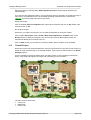
Schedule Plus is a software package which can be connected to the C-Bus home automation
system. It can provide a central point of control and scheduling of services throughout the home.
The Schedule Plus Software can display a series of "pages" which contain clickable controls
associated with various loads throughout the C-Bus Network. These pages may be re-configured
by means of the Schedule Plus Software.
The appearance of every Schedule Plus setup will be unique, so your Schedule Plus
display may not look like the examples in this guide.
Through the Schedule Plus Software the user may set up "scenes" with multiple loads ramping to
their respective target levels together to set a particular mood at the press of a soft button. The
Schedule Plus Software can also control loads according to a schedule.
A run-time version of Schedule Plus is supplied which disables the editing features. If desired, you
can use the normal version of Schedule Plus to edit the project and then remove the editing
version of Schedule Plus from the computer and use the run-time version for the day to day use.
© Copyright 2000-2005 Clipsal Integrated Systems Pty Ltd
Page 4
Intelligent Building Series
3
Schedule Plus Programmer's Guide
Menu Notation
The menu selections in this document will follow a simple menu description notation. If the user is
using the Schedule Plus Software and chooses, for example, the menu selection Edit, then from
the resulting menu chooses Select and then from that menu chooses Select All then this process
will be described as Edit | Select | Select All as a shorthand description of this operation. Certain
menu items offer several options, any one of which may be selected. In this case we can specify a
range with square brackets and ellipses. For example, the width of a tick mark can vary from 1 to
5, this can be denoted by [1..5].
© Copyright 2000-2005 Clipsal Integrated Systems Pty Ltd
Page 5
Intelligent Building Series
4
Schedule Plus Programmer's Guide
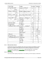
Definitions
The following definitions are useful in discussing the Schedule Plus Software:
Term
Definition
Component
A graphical object displayed on a Schedule Plus page. Components
include soft keys, images, text, clocks, temperature sensors and other
items.
Page
A page is an assortment of related components that represents something
understandable to the user.
Page Link
A method of causing the display to jump to another page.
Schedule
A schedule is a sequence of events that are to occur at particular times or
dates in the future.
Load
A load is an electrical device controlled via a C-Bus output unit. Most
loads are lights, but may be any device such as sprinklers, AC Power
points, heaters, projection screen motors, AV equipment (via IR) etc.
Lighting Zone
Refers to an illuminated area. In Schedule Plus a zone is a C-Bus Group
Address representing one or many loads connected to a C-Bus output
unit. All the lights in your dining room might be in one zone.
Scene
A scene is defined as the combination of loads distributed in various
control zones with different levels. The scene can be set up with the
Schedule Plus Software and assigned to soft keys on the Schedule Plus
Software.
Ramp Rate
The ramp rate indicates the length of time it takes for a load to ramp to a
desired level.
Input Unit
An input unit is a C-Bus unit which the user interacts with to make things
happen on a C-Bus Network (Schedule Plus itself, a key input unit or
passive infrared sensor are examples).
Output Unit
An output unit is a C-Bus unit which delivers power to loads (a relay and
dimmer are examples).
C-Bus related definitions which are useful when discussing Schedule Plus programming are given
in the following sections.
© Copyright 2000-2005 Clipsal Integrated Systems Pty Ltd
Page 6
Intelligent Building Series
5
C-Bus Concepts
5.1
About C-Bus
Schedule Plus Programmer's Guide
C-Bus is a microprocessor controlled wiring system that uses Unshielded Twisted Pair cable (UTP
cable) as its communication medium. C-Bus is intended to be used mainly as a lighting
management system although it has the capability of interfacing with other services, such as
security systems and air-conditioning.
C-Bus may be integrated as part of overall energy management system. C-Bus is highly flexible in
the way it operates because each device on the Bus has its own in-built microprocessor. These
devices can be programmed in the field to provide optimum energy management conditions in any
installation.
Information comes from Input Units such as Key Units, Light Level Sensors and Infrascans.
Messages are sent via the Bus to Output Units such as Relays and Dimmers. Connections
between Input Units and Output Units are defined by Group Addresses (GA); thus GA can be
considered as virtual wires. C-Bus Installation Software allows the user to modify GA as well as
other parameters. All parameters including GA are stored in unit's non-volatile memory.
C-Bus is a truly distributed system. It does not have a central processing unit; C-Bus intelligence is
distributed across entire network.
For further details about C-Bus, see the Clipsal web site at http://www.clipsal.com/cis.
5.2
Networks
Where a project exceeds the physical limitations of a single C-Bus network, the project may need
to be segregated into several networks. Each network will need to be connected to one or more
other networks via a bridge.
Some definitions are required for the understanding of C-Bus Networks :
· The computer uses a PC Interface (or PCI) to send and receive messages from C-Bus.
· C-Bus Networks which the computer is connected to are referred to as "Local" or "Connected
Networks".
· The C-Bus Network which is used when creating new Components etc is referred to as the
"Default" Network
· All other Networks are referred to as Remote Networks.
· A C-Bus Bridge is used to connect two C-Bus Networks together and to transmit messages from
one Network to the other.
· A Fully Connected Network has every Network connected to every other Network via a C-Bus
Bridge, and behaves as one large C-Bus Network.
· Application Connect Mode is a setting in a C-Bus Bridge that can be used to automatically send
all messages from one of its Networks to the other. This makes the two Networks behave as if
they were connected (there are some limitations though).
© Copyright 2000-2005 Clipsal Integrated Systems Pty Ltd
Page 7
Intelligent Building Series
Schedule Plus Programmer's Guide
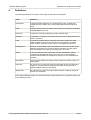
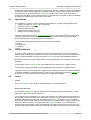
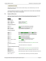
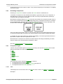
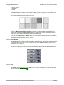
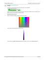
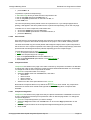
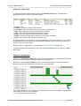
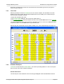
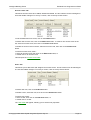
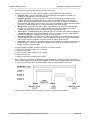
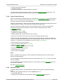
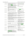
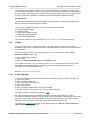
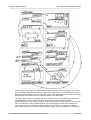
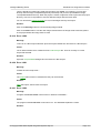
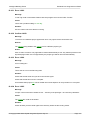
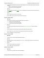
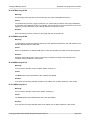
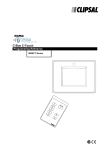
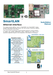
How the system works depends on how the networks are constructed. The networks below are
each connected to other networks via a bridge. Each bridge is used in Application Connect mode
(see the C-Bus documentation for more details). Each network has a Touchscreen on it which is
capable of transmitting messages addressed to any network. The computer is running the
Schedule Plus software, and is connected to Network 1 via a PC Interface.
The Schedule Plus software on Network 1 can send commands to its local network (Network 1)
which will be automatically bridged across to the other networks. Each of the other Touchscreens
will see the command and act accordingly (updating indicators etc). Note that it is necessary to
have the PC Interface set to LOCAL SAL mode for this to work. Please contact CIS Technical
Support for information on how to perform this setting.
The Schedule Plus software on Network 1 can also send bridged commands addressed to any one
of the other networks. In this case, the command will arrive as an inter-network command and so
the bridges will not automatically resend this across to the other networks.
If the Touchscreen on Network 2 sends a command to its local network, then the command will be
automatically sent across the bridge to Network 1. However, since it will arrive at Network 1 as an
inter-network command, it will not then be sent across the other bridges to the other networks. In
this case, the Touchscreen and Schedule Plus software on Network 1 will see the command, but
the others (on Networks 3 and 4) will not.
© Copyright 2000-2005 Clipsal Integrated Systems Pty Ltd
Page 8
Intelligent Building Series
Schedule Plus Programmer's Guide
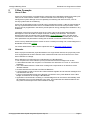
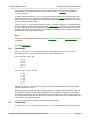
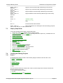
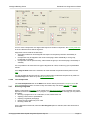
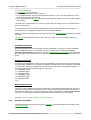
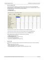
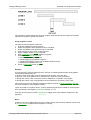
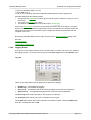
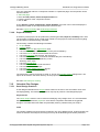
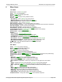
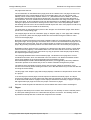
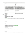
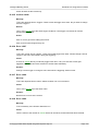
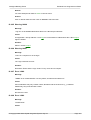
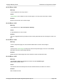
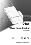
Fully Connected Networks
To make all C-Bus devices see all commands (and hence stay synchronised with each other), you
will need fully-connected networks where every network is connected to every other network via a
bridge, as shown below :
In the case of fully connected networks, in the Project Details dialogue, Options Tab you should
set the Model Networks Independently to off.
If you have the same Group Address on the same Application used on different networks, they will
be treated as being the same. Hence if you send a command to switch on Group Address 20 on a
remote network, you will see that GA 20 on the local network is also on.
Note that it will not have sent a command to the Local Network. If you want a command
to go to the local network as well as other networks at the same time, you will need to
use scenes.
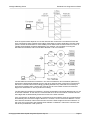
Notes regarding use of networks which are not fully-connected
If you have networks that are not fully-connected and you want to send a command to control a
Group Address on another network, you can select the destination network for the command.
When the command is sent, the path through the various bridges to the remote network will be
included.
If the local network is connected to adjacent networks by bridges in Application Connect mode,
messages will be sent between the networks by the bridges.
Message Tunneling
If the bridges are set up to send messages from remote networks back to the local network, you
can monitor the state of the remote networks. Networks that are adjacent to the Local Network can
send messages back to the Local Network using Application Connect Mode. Networks that are
further away, can use Message Tunneling to send messages back to the Local Network.
© Copyright 2000-2005 Clipsal Integrated Systems Pty Ltd
Page 9
Intelligent Building Series
Schedule Plus Programmer's Guide
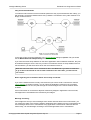
If Application Connect Mode / Message Tunneling is not enabled, it is best to avoid using indicators
showing the state of Group Addresses on Remote Networks. If the software sends a command to
a remote network, any Schedule Plus Components will show the correct state. If the state is
changed by something on the remote network, the command may not appear on the local network,
and hence the software will not show the correct state.
5.3
Applications
An "Application" is used to combine related system behaviour. Typically used applications are :
· Lighting (numbers 30 - 5Fhex, 38 is the default)
· Irrigation (number 71 hex)
· Heating (number 88 hex)
· Trigger Control (number CA hex)
· Enable Control (number CB hex)
The above Applications consist of Group Addresses and can be controlled by the Schedule Plus
software. Note that you should never use any Application number other than the ones shown
above, otherwise there may be unforeseen consequences.
There are other Applications used which are not directly controllable :
· Security
· Measurement
· Telephony
· Time
5.4
Group Addresses
A Group or Group Address is an "address" of one or more output loads. The Group Address is
used to match an input device (keypad, touchscreen etc) with an output device (relay, dimmer etc)
channel. Group Addresses can be given names ("tags") using the C-Bus Installation Software.
Note that the output unit logic is not modelled. The group addresses are controlled, not the output
terminals.
In the Trigger Control Application, the Group Addresses are referred to as "Trigger Groups".
In the Enable Control Application, the Group Addresses are referred to as "Enable Groups".
The generic term for Group Addresses, Trigger Groups and Enable Groups is "Network Variables".
A Network Variable is something that stores a value, and is synchronised across the Network (ie.
all devices on the Network store the same value for the Network Variable).
5.5
Levels
Levels
Every Group Address has a level (or value) between 0 (0%) and 255 (100%).
How Levels are Used
In the Lighting Applications, the level corresponds to the lighting intensity or brightness. In other
Applications, the level is used in other ways :
In the Trigger Control Application, the "Levels" are referred to as "Action Selectors" because they
are selecting some sort of action to be performed. In Trigger Control, setting a Trigger Group to a
particular Action Selector (Level) can be used to trigger a Scene or start an Irrigation program.
Note that the EXACT Action Selector (Level) must be set, and ramping the Trigger Group through
this Level will have no effect. You must also set the ramp rate to zero (i.e. an instantaneous
change) rather than ramping to the Level. Ramping to the Action Selector (Level) may still cause
the event to be triggered, but it will happen when the message is sent, NOT at the end of the ramp.
© Copyright 2000-2005 Clipsal Integrated Systems Pty Ltd
Page 10
Intelligent Building Series
Schedule Plus Programmer's Guide
In the Enable Control Application, the Levels are called "values". In Enable Control, setting an
Enable Group to a particular value (level) can be used to enable a Schedule or to enable the
Irrigation controller.
In Trigger and Enable Control, C-Bus Tags should be used to reference the Action Selectors and
Values (ie Levels). Do not set the Action Selectors and Values in Percent because the value you
are trying to set may be in between two percentage levels (in fact in these Applications, the concept
of percent does not make sense).
To use a Network Variable value (Level) as a trigger or to enable something, it is essential that the
C-Bus message that set the value must reach the Local Network. If a switch on a remote network
is used to set a value, then there will need to be a C-Bus bridge to get the message onto the Local
Network. Note that it is also necessary to ensure that the Tag for the value is created on both the
Local Network and on the remote network.
Notes
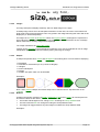
The level of the Group Address associated with a Component controls the Visible Properties of the
component.
See also Load Monitor
5.6
Percentage
C-Bus Group Address Levels are expressed as a number (decimal or hexadecimal) or as a
percentage (0-100%). The conversion between the level and percent is :
Level = (Percent * 255) / 100
0% = 0
1% = 2
2% = 5
3% = 7
4% = 10
etc.
Percent = 100 * (Level + 2) / 255
0 = 0%
1 = 0%
2 = 1%
3 = 1%
4 = 1%
5 = 2%
etc.
Example : If level is 41, then Percent = 100*(41+2)/255 = 16.784 and we keep the whole number
(16) and hence level 41=16%.
Because there are 256 discrete levels (0 to 255) but only 101 different percentages (0 to 100), not
all levels have a unique corresponding percentage. If you are setting a group level as a percent,
there will be some levels which you are unable to set. For example, if you want to set to a level of
5, you can set the level as 2% (see above). If you want to set to a level of 6, you will be unable. The
next closest in this case will be 7 (3%).
A full list of conversions is provided in the Schedule Plus help file.
5.7
Ramp Rates
A C-Bus Group Address can be set to ramp to a Level over a certain amount of time. This time is
© Copyright 2000-2005 Clipsal Integrated Systems Pty Ltd
Page 11
Intelligent Building Series
Schedule Plus Programmer's Guide
called the Ramp Rate. Ramp Rates supported by C-Bus are :
· 0 seconds (instantaneously)
· 4 seconds
· 8 seconds
· 12 seconds
· 20 seconds
· 30 seconds
· 40 seconds
· 1 minute
· 1.5 minutes
· 2 minutes
· 3 minutes
· 5 minutes
· 7 minutes
· 10 minutes
· 15 minutes
· 17 minutes
Note that the ramp rate is the time to change the level from 0% to 100% or vice versa. If the level is
at 50% and you execute a ramp to 100% with a 4 second ramp rate, it will only take 2 seconds.
5.8
C-Bus Tags
All C-Bus Applications, Group Addresses and Levels are assigned a number from 0 – 255 (0 – FF
hexadecimal). Remembering these numbers is inconvenient, so a name can be assigned to them.
The name is referred to as a "tag".
Examples of tags are :
· Network Tags
· "Local Network"
· "Third Floor"
· Application Tags
· "Lighting"
· "Control"
· Group Address Tags
· "Kitchen Light"
· "Pool Motor"
· Level Tags
· "Welcome Home Scene"
· "Irrigation On"
There are two ways of creating tags for use with a project :
· From the Software – in a dialogue box that has a drop-down list to select a group address or
level, sometimes there will be two buttons alongside which allow you to add a new tag or to edit
the selected one
· Using the C-Bus Tool Kit – see C-Bus documentation for details (sometimes this is the only
method available)
To load the C-Bus tags into a project, open the Project Details dialogue box and select the C-Bus
project with the required tags.
It is easiest to load the tags for a project before you start. You can, however, create a project and
assign group addresses, then load the tags later.
See also Printing
5.9
Hexadecimal Numbers
A Hexadecimal number is a number represented in "base 16". Everyday numbers are represented
© Copyright 2000-2005 Clipsal Integrated Systems Pty Ltd
Page 12
Intelligent Building Series
Schedule Plus Programmer's Guide
in decimal, which is base 10. In the decimal system numbers are expressed with 10 symbols; the
familiar digits 0-9. The hexadecimal system uses 16 symbols, the ten digits (0 to 9) plus six letters
(A to F) to stand for "digits".
In the decimal system, once the number 9 (the last digit) is reached, a symbol has to be placed in
the next column (the "tens" column) to create a number with two digits. In the hexadecimal system,
in exactly the same way, once the number "F" (the last digit) is reached a symbol must be placed in
the next column (the "sixteens" column).
A comparison between the two is shown below (decimal = hexadecimal) :
0 = 00
1 = 01
2 = 02
3 = 03
4 = 04
5 = 05
6 = 06
7 = 07
8 = 08
9 = 09
10 = 0A
11 = 0B
12 = 0C
13 = 0D
14 = 0E
15 = 0F
16 = 10
17 = 11
18 = 12
19 = 13
20 = 14
21 = 15
22 = 16
23 = 17
24 = 18
25 = 19
26 = 1A
27 = 1B
28 = 1C
29 = 1D
30 = 1E
31 = 1F
32 = 20
33 = 21
A complete list is provided in the Schedule Plus help file.
© Copyright 2000-2005 Clipsal Integrated Systems Pty Ltd
Page 13
Intelligent Building Series
6
Configuring the Schedule Plus Software
6.1
Starting the Software
Schedule Plus Programmer's Guide
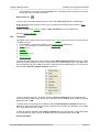
The simplest way to start the Schedule Plus software is to use the start menu item. If you have
installed the software using the defaults, then click on the Start button, click on Programs, then
Clipsal, then Schedule Plus then Schedule Plus.
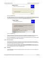
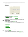
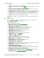
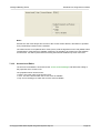
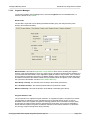
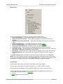
When the program starts, you will see the Project Details wizard which will allow you to create a
New Project, Open a Project, or re-open an existing project.
If this is the first time you have used the software, select the Open an Existing Project button,
select one of the example projects, click on the OK button, then click on the Finish button.
Note that the Schedule Plus should not be run at the same time as the C-Bus Tool Kit. They
use C-Gate in different modes and also there can be problems caused by the two programs
simultaneously accessing the C-Bus tag database.
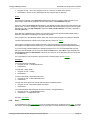
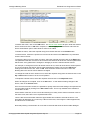
6.2
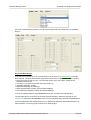
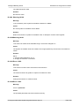
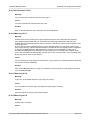
Software Screen
The Schedule Plus Software is a Windows™ application that uses a graphical representation of
various controls and objects associated with the programming of the Schedule Plus Software.
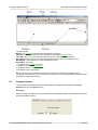
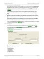
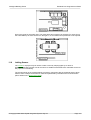
When the Schedule Plus Software is opened, you will see a screen something like that below.
© Copyright 2000-2005 Clipsal Integrated Systems Pty Ltd
Page 14
Intelligent Building Series
Schedule Plus Programmer's Guide
The features are :
Menus : the menus provide access to the software functions
Title Bar : this shows the name of the software and the loaded Project (if any)
Tool Bars : the Tool Bars provide quick access to the common software functions
Scroll Bars : these allow you to select which part of the work space you wish to look at
Work Space : this is where you create and edit the project
Status Bar : this shows :
· the status of the C-Bus connection
· details of the selected Component
· the status of the Schedules
· the status of the Logic Engine
Before a project can be created the design environment provided by the Software can be
configured to operate in a way most convenient to the user. The following sections describes these
preliminary configuration settings.
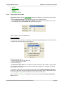
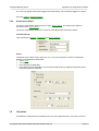
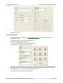
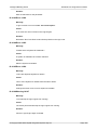
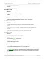
6.3
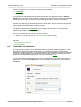
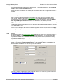
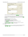
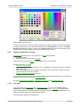
Program Options
The Schedule Plus Software can have various options configured by selecting the Program
Options item from the Options menu.
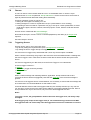
Auto Save
When Auto Save is enabled, the project will be saved at regular intervals. The interval can be set to
between 5 and 60 minutes.
© Copyright 2000-2005 Clipsal Integrated Systems Pty Ltd
Page 15
Intelligent Building Series
Schedule Plus Programmer's Guide
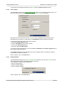
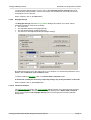
Connections
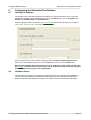
This tab allows you to choose how to connect to the Internet.
The Internet port number is used for Internet Access (via ServerX for example).
Reports
This allows you to select whether you want your Project Summary and Check Project reports
presented as an HTML report (to read or print using a web browser) or as a text file for inclusion in
some other document.
Operation Mode
It is also possible to select the type of cursor for when Operation Mode is running. If you are using
a Touch Panel PC, it may be desirable to have no cursor displayed.
Other
By default, when the right mouse button is clicked on a component, the action for that component
is executed. Alternatively you can have a pop-up menu appear when the right mouse button is
clicked.
© Copyright 2000-2005 Clipsal Integrated Systems Pty Ltd
Page 16
Intelligent Building Series
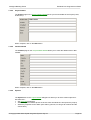
Schedule Plus Programmer's Guide
If you wish to have the Component Properties editor open when a component is first placed on a
Page, select the Open Editor When Placing Components check box.
6.4
Operation Mode
To disable editing functions, the Schedule Plus software can be placed in Operation Mode by
either:
· selecting the Operation Mode item from the Options menu; or
· by pressing CTRL + S
· clicking on any component with the Operation Mode Special Function property set.
To get out of Operation Mode, you can
· press CTRL + S ; or
· click on any component with the Exit Operation Mode Special Function property set.
Operation Mode does the following things :
· Components are activated by a left or right mouse click (this is useful for running on Touch
Panel PCs)
· The menus and tool bars are hidden
· The Window is set to the same size as the Project Screen Size
If the Project Screen Size is the same as the Computer Screen Size, there will be no program
border or caption bar. To make the project fill the screen, but still have the program border and
caption bar, set the Project screen size to have a height and width a few pixels less than the
computer screen size.
Note that the Operation Mode cursor image can be set in the Program Options dialogue box.
See also
Program Options
Logging
Command-Line Parameters
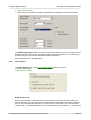
6.5
Internet Access
The Schedule Plus program can be accessed via the Internet (World Wide Web). Please refer to
the Internet Access User Guide for full details.
To allow the project to be controlled via the Internet, select the Connect to WWW item from the
Options menu. This will open the port selected in the Program Options to allow control via a CGI
script or ServerX.
When an application connects to the ServerX port, it will be indicated that user access is locked in
red writing across the screen. During this time, it will not be possible to control the software from
the PC. This prevents more than one user from controlling the software at the same time which
would cause confusion. To "unlock" the ServerX access, press Ctrl + U.
© Copyright 2000-2005 Clipsal Integrated Systems Pty Ltd
Page 17
Intelligent Building Series
Schedule Plus Programmer's Guide
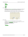
There are three factors which affect the Internet download speed :
· Image quality
· Screen Size
· Complexity
The quality of the JPEG image returned to the web browser can be selected from the Options |
JPEG Quality menu item. A low quality file is smaller than a high quality file and will download more
quickly via the Internet. If you have a slow connection to the Internet, it may be preferable to
sacrifice some image quality for improved speed.
Another factor affecting the download speed is the Screen Size. A larger screen size will generally
take longer to download because the image is larger.
The last factor affecting download speed is the complexity of the screen. If you have a plain
background, with just a few components, it will be quite fast. If you have lots of components, and in
particular, big images, it will be much slower.
There are two things that can not be done via the Internet :
· Clicking on a component with most Special Functions will do nothing
· You can not perform any function which would show a dialogue box (eg. Editing Scenes etc).
See also
- Command-Line Parameters
- Program Options
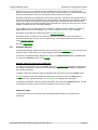
6.6
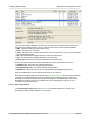
Command Line Parameters
The Schedule Plus program can be started with various properties enabled upon start-up. These
properties are called Command-Line Parameters. For example the program can start with a
particular file loaded, and with the C-Bus communications channel already open. This is particularly
useful when the program is set to automatically start when the computer is started (by having the
program in the Windows StartUp folder) or if you have a Desktop shortcut.
To set the command-line parameters, right click on the Schedule Plus shortcut (on the desktop or
Start menu), and select the Properties item. The command-line parameters are entered into the
Target box.
© Copyright 2000-2005 Clipsal Integrated Systems Pty Ltd
Page 18
Intelligent Building Series
Schedule Plus Programmer's Guide
The syntax is as follows :
ExeFilename [filename] [/cgate] [ /www ] [ /jpeg=level ] [/operate] [/nosplash]
[/syncschedules] [/log=enable | /log=save | /log=append] [ /autosave | /autosave=time ]
Where :
· ExeFilename is the path and file name of the executable file. Note that if there are spaces in the
executable file path or file name, the ExeFileName must be enclosed within double quotes.
· Filename is the name of a file to be loaded. Note that if there are spaces in the file name, the file
name must be enclosed within double quotes.
· /cgate selects whether C-Bus communications are to be opened with C-Gate.
· /www determines whether to connect via the World Wide Web
· /jpeg determies the compression of jpeg images for www access. Options are low, medium,
high or best (default is high).
· /operate puts the program in Operation Mode
· /nosplash shows the splash screen for only the minimum amount of time
· /syncschedules performs a Synchronise to Schedules after connection to C-Gate
· /log=enable enables the logging
· /log=save enables the logging and saves it to a log file
· /log=append enables the logging and appends it to the log file
· /autosave sets the autosave feature on, with the default duration (15 minutes)
· /autosave=time sets the autosave on with the specified time (in seconds)
The ExeFileName must be present, and must be first. The FileName is optional, but if used, must
be second. All other parameters are optional and may occur in any order. There must be a space
between each parameter.
Examples :
"C:\Clipsal\Schedule Plus.exe" "C:\Clipsal\Schedule Plus\Projects\MyHouse.ctd"
will load the file MyHouse.ctd at start-up
"C:\Clipsal\Schedule Plus.exe" "C:\Clipsal\Schedule Plus\Projects\MyHouse.ctd" /cgate
/log=save
will load the file MyHouse.ctd at start-up and connect via C-Gate, with logging enabled.
"C:\Clipsal\Schedule Plus.exe" "C:\Clipsal\Schedule Plus\Projects\MyHouse.ctd" /cgate /www
/jpeg=high
will load the file MyHouse.ctd at start-up and connect via C-Gate, with web access with high quality
jpeg images
See also Desktop Shortcut.
6.7
Creating a Desktop Shortcut
To create a desktop shortcut which will start the software and load the currently loaded file, select
the Create Desktop Shortcut item from the File Menu.
The desktop shortcut will be created with the following parameters :
· The currently loaded file
· The current connection to C-Bus
Once the shortcut has been created, you may add other Command-Line Parameters by selecting
the shortcut, right clicking on it and setting the properties.
© Copyright 2000-2005 Clipsal Integrated Systems Pty Ltd
Page 19
Intelligent Building Series
7
Using the Schedule Plus Software
7.1
Tool Bars
Schedule Plus Programmer's Guide
All program functions are available via menu items. Many of the commonly used functions are also
available on the tool bars, which are the panels with a series of buttons on them.
The tool bars are at the top of the screen by default, but the tool bars can be configured to suit
personal preference by :
· moving them onto any position on the screen (click on the vertical bar on the left of the toolbar
and drag it)
· docking them to another place on the screen (drag a toolbar to the top, bottom, left or right of
the screen)
· closing them (by dragging them onto the screen, then clicking on the close button)
In addition to manipulating individual tool bars, they can be modified together :
· Hide/close all tool bars by selecting Hide Toolbars from the Options menu
· Show all hidden tool bars by selecting Show Toolbars from the Options menu
· Restore the original position of all tool bars by selecting Restore Toolbars from the Options
menu
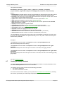
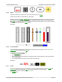
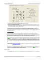
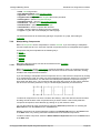
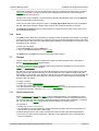
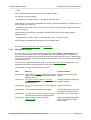
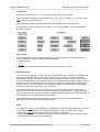
The Main Form toolbars are shown below :
Project Toolbar
The Buttons' functions are (respectively) :
· Project Details
· Add Page
· Open a Project
· Save the Project
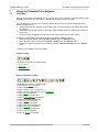
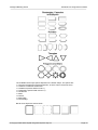
Place Components Toolbar
The Buttons' functions are (respectively) :
· Select which Shape to place
· Place a Shape Component
· Place a C-Bus Button Component
· Place a button Component (e.g. for a Page Link)
· Place a Text Component
· Place an Image Component
· Place a Level Indicator Component
· Place an Indicator Component
· Place a Clock Component
· Place a Slider Component
· Place a Bar Slider Component
· Place a Monitor Component
· Place a Selector Component
· Place a Tool Component
· Place an HTML Component
© Copyright 2000-2005 Clipsal Integrated Systems Pty Ltd
Page 20
Intelligent Building Series
Schedule Plus Programmer's Guide
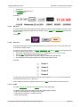
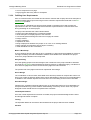
Page Select Toolbar
This allows you to select which page you wish to view.
Access Control Toolbar
The button allows you to Log-in / Log-out. The text shows you to current Access Level.
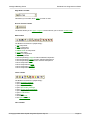
Edit Toolbar
The Buttons' functions are (respectively) :
· Cut Component
· Copy Component
· Paste Component
· Paint Format of Component
· Undo last action
· Select All Components
· Align Components
· Set Component(s) Height to match selected Component
· Set Component(s) Width to match selected Component
· Set Component(s) Size to match selected Component
· Move Component Back
· Move Component to Back
· Move Component Forward
· Move Component to Front
Tools Toolbar
The Buttons' functions are (respectively) :
· Open Schedule Manager
· Open Scene Manager
· Open Irrigation Manager
· Open Special Day Manager
· Open Access Control Manager
· Open Logic Editor
· Open Load Monitor
· Open Log
· Set default Font
· Set Operation Mode
Time Toolbar
© Copyright 2000-2005 Clipsal Integrated Systems Pty Ltd
Page 21
Intelligent Building Series
Schedule Plus Programmer's Guide
This shows you the current date and time. Double clicking on the toolbar allows you to set the
computer date and time.
To see the function of any item on a toolbar, hold the mouse over the item in the Schedule
Plus software, and you will see a hint pop-up.
7.2
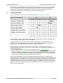
Keyboard Shortcuts
There are various actions which can be performed using the keyboard which can be much faster
than using a mouse to select a menu item. These Keyboard Shortcuts are listed below :
Shortcut
Action
Page Selection
CTRL + Page Up
CTRL + Page Down
CTRL + Home
Select the previous Page
Select the next Page
Selects the Start-up Page
Component Selection
CTRL + A
CTRL + E
CTRL + Left Click
Shift + Left Click
Select all of the Component(s) on the Page
De-select all of the selected Component(s)
Toggle selection of a Component
Drag to select all Components in an area
Component Editing
CTRL + á
CTRL + â
CTRL + ß
CTRL + à
Move selected Components up by one Grid spacing
Move selected Components down by one Grid spacing
Move selected Components left by one Grid spacing
Move selected Components right by one Grid spacing
CTRL + C
CTRL + X
CTRL + V
CTRL + F
CTRL + Delete or Delete
Copy the selected Component(s)
Cut the selected Component(s)
Paste the selected Component(s)
Paint the format to the selected Component(s)
Delete the selected Component(s)
CTRL + Z
Undo the last action
CTRL + G
Secondary Selection(s).
Copy the group address from the Primary Selection to the
Esc
Cancel the Placement of a Component
Component Alignment and Size
CTRL + H
Primary Selection
CTRL + W
Primary Selection
CTRL + B
the Primary Selection
Make the height of Secondary Selection(s) the same as the
CTRL + Shift + A
Align the Secondary Selection(s) to the Primary Selection
Make the width of Secondary Selection(s) the same as the
Make both (height & width) of Secondary Selection(s) the same as
© Copyright 2000-2005 Clipsal Integrated Systems Pty Ltd
Page 22
Intelligent Building Series
CTRL + Shift + L
Selection
CTRL + Shift + T
Selection
CTRL + Shift + R
Selection
CTRL + Shift + B
Selection
Schedule Plus Programmer's Guide
Align the Left of the Secondary Selection(s) to the Primary
Align the Top of the Secondary Selection(s) to the Primary
Align the Right of the Secondary Selection(s) to the Primary
Align the Bottom of the Secondary Selection(s) to the Primary
Other
CTRL + S
Operation Mode
F1
Help
Alt + F4
Exit the Schedule Plus software
CTRL + Shift + E
Raise a deliberate error message for test and training purposes.
This is not a real error. Do NOT report to CIS.
7.3
Step by Step Guide
To use the Schedule Plus Program, follow these steps :
· Create any C-Bus Tags needed using the C-Bus Tool Kit
· Create a directory to put your project in (all image files will be put there) - Schedule Plus can
do this for you when you Save the Project
· Create a new project
· Set the Project Details
· Add pages
· Add components to each page
· Add links to the pages
· Create Scenes
· Create Schedules
· Set up the Irrigation Control if required
· Set up the Access Control if required
· Check the Project for errors, and correct them
· Check the project Summary if desired
· Test the project (Operation Mode)
· Save the project
· Archive the files for later use
7.4
Creating and Saving Projects
7.4.1
Project
A Schedule Plus Project consists of the following things created for the end user to use :
· Pages of Components
· Scenes
· Schedules
· Irrigation Control
· Access Control
· Special Days
· Logic
All of this data is saved in the Project File. There are other things which are also stored in the
directory with the Project file :
· any images used by the project
· Log files
· Project Details Reports and Error Reports
© Copyright 2000-2005 Clipsal Integrated Systems Pty Ltd
Page 23
Intelligent Building Series
Schedule Plus Programmer's Guide
· Load Duration data
7.4.2
Opening a Project
To open a project, either click on the Open button of the tool bar, or select the Open item from the
File menu. Select the directory where your project is stored, and select the file name. The default
file extension of a project file is CTD. Click on OK.
Project files with the extension ".cte" are secure project files which have been encrypted to protect
against tampering.
To open a project which has been recently opened, select Reopen from the File menu.
To add pages from a project to the one which is currently open, select Import Page from the File
menu or select Reimport Page from the File menu.
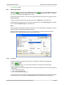
Notes :
If an image file is missing when a project is opened, an error message will be displayed. A large X
will be placed where the missing images should be.
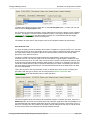
While the Open File dialogue box is open, you can right click on the area where the files are
displayed (not on a file) and select how you want them sorted :
7.4.2.1
File Types
The file extensions of the file types used by the Schedule Plus software are listed below :
· CTD : Project data file
· CTP : Template file
· CTE : Secure Project file - this encrypts the file when it is saved to prevent tampering
· CTA : Project Archive file
· XML : this was the Project file used by older versions of this software, and can still be opened by
this version
· ~CTD : project back-up file
· ~CTP : back-up template file
· ~CTE : back-up secure Project file
To convert all of the Project files in a directory (and its sub-directories) from the old format (*.XML)
to the new format (*.CTD), select the Convert Files item from the File menu and select the
© Copyright 2000-2005 Clipsal Integrated Systems Pty Ltd
Page 24
Intelligent Building Series
Schedule Plus Programmer's Guide
required directory. You will be presented with a list of all of the files which have been converted.
7.4.2.2
Loading C-Touch Projects
It is common to have C-Touch Touchscreens installed in an installation and to have the Schedule
Plus software running on a PC at the same time. It is possible to load a C-Touch project file into
this software to save having to enter the same data again. To do this :
· Open the C-Touch Project File
· Resize the Project if required
· Make any changes as necessary
· Save the file under a different name
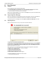
7.4.3
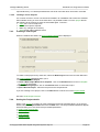
Creating a new Project
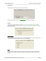
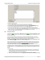
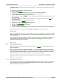
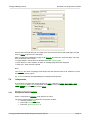
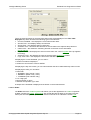
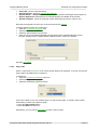
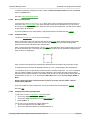
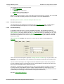
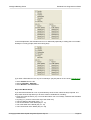
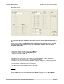
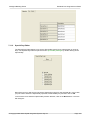
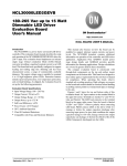
When the software first starts, the Project Details Wizard will be displayed :
To create a new project at any other time, select the New Project menu item from the File menu.
The Project Details Wizard will allow you to
· Create a New Blank Project
· Create a New Project Based on a Template : click on the Browse button to load a Template
or Theme for the Project
· Open an Existing Project : click on the Browse button to select the Project
· Open a Recent Project : select the Project from the drop-down list
If you are creating a new project, click on the Next button to set the rest of the Project Details.
See also Good Design Practices
7.4.4
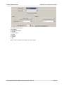
Setting the Project details
When a new Project is created, all of the parameters will be set to default values. To set Project
details, select the Project Details item from the Edit menu. The Project Details Wizard will appear
which will allow you to set various Project-related parameters :
· Project Type / Screen Size
· C-Bus Project
· Detault Network
· Project Details
· Installer Details
© Copyright 2000-2005 Clipsal Integrated Systems Pty Ltd
Page 25
Intelligent Building Series
·
·
·
·
·
7.4.4.1
Schedule Plus Programmer's Guide
Options
C-Bus Options
Location
Daylight Savings
Auto Page Creation
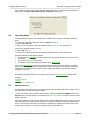
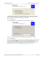
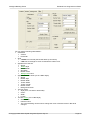
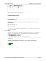
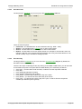
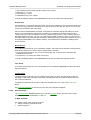
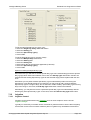
Project Type / Screen Size
The Screen Type tab on the Project Details dialogue box allows you to select the Project screen
size :
· Selecting Screen Size will set it to the current size of the computer screen.
· Select QVGA, VGA, SVGA, XGA, SXGA or UXGA to set the screen to standard screen sizes.
· To set another size, select Custom and enter the desired size.
When complete, click on the Next button.
Project Re-Sizing
The Project Screen Size can be changed by selecting the Resize Project item from the File menu.
A dialogue box will appear giving various options :
Select the desired size by :
· Selecting a size from the drop-down list
· Enter the desired size in pixels
· Enter a Scaling (%)
If the Maintain Aspect Ratio box is selected, the Aspect Ratio (the ratio of width to height) will be
kept constant. This means that if you make a change to the width boxes, the height will change
accordingly and vice versa.
To have the components moved to their new positions, select the Adjust Component Position
check box. If this is not selected, the project screen size will change, but the components will not
be affected (unless they would be off the screen with the new screen size).
You can have the Components resized to the same scale by selecting the Adjust Component
Size check box.
© Copyright 2000-2005 Clipsal Integrated Systems Pty Ltd
Page 26
Intelligent Building Series
Schedule Plus Programmer's Guide
To have all of the Components placed on the Grid, select the Snap To Grid check box.
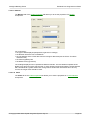
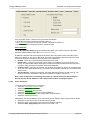
7.4.4.2
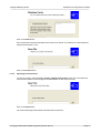
C-Bus Project
The Unit Address page of the Project Details Wizard allows you to select the a C-Bus project. A CBus project must be selected from the list in order for C-Bus Tags to be available.
Most of the time you will want to use the C-Gate on your Local Machine (the computer which
Schedule Plus is running on). In this case, the Local Machine option needs to be selected.
If you want to connect to C-Gate on a remote machine :
· select the Remote Machine option
· enter the IP Address of the remote machine
· click on the Load Projects button
· select the required C-Bus Project
If you have C-Gate configured to use a non-standard Command Port or Status Change Port, the
port numbers should be entered.
The C-Gate Test option can be selected if you want to regularly send a command to C-Gate to
verify that the connection is still OK.
When complete, click on the Next button.
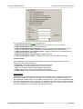
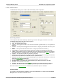
7.4.4.3
Default Network
The Default Network page of the Project Details Wizard allows you to select the network that you
will be using the most often. The default network is used for :
· the network for newly created components
· tags for scene triggers
· tags for irrigation triggers
· tags for schedul enabling
When complete, click on the Next button.
© Copyright 2000-2005 Clipsal Integrated Systems Pty Ltd
Page 27
Intelligent Building Series
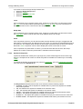
7.4.4.4
Schedule Plus Programmer's Guide
Project Details
The Project page on the Project Details Wizard allows you to enter details of the Project (name,
location etc).
When complete, click on the Next button.
7.4.4.5
Installer Details
The Installer page on the Project Details Wizard allows you to enter the details of the C-Bus
Installer :
When complete, click on the Next button.
7.4.4.6
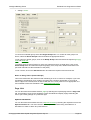
Options
The Options tab on the Project Details dialogue box allows you to select various options for
Schedule Plus :
· Set Time-Out parameters
· Set Start-up screen details (these are shown when Schedule Plus first opens the project)
· Select the properties for the Alarm (how often it goes off, how long it will continue and the
snooze time)
© Copyright 2000-2005 Clipsal Integrated Systems Pty Ltd
Page 28
Intelligent Building Series
·
·
Schedule Plus Programmer's Guide
The network modelling
Metric Units can be selected to display Temperature in Centigrade, rather than Fahrenheit.
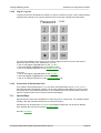
The Enable Popup Editor option is for when you have the software running on a computer with no
keyboard, but with a touch screen. Anywhere that data needs to be entered, you can use the popup editor so that you can edit new data without needing a keyboard.
When complete, click on the Next button.
7.4.4.7
C-Bus Options
The C-Bus Options page on the Project Details Wizard allows you to select :
· various C-Bus options.
· The network modelling
Ramp Groups to Off
When a group address is ramped to level 0, the command is received by all C-Bus Units on the
network. On some old C-Bus input units, the status indicator will go off as soon as this message is
seen, even though the level is still above 0 for some time. For this reason, many devices send a
"ramp to level 1" command followed by an "off" command when the level gets to 1. In this case, the
© Copyright 2000-2005 Clipsal Integrated Systems Pty Ltd
Page 29
Intelligent Building Series
Schedule Plus Programmer's Guide
input unit status indicators will show the state correctly. To select this behaviour, select the Ramp
Groups to Level 1 then send Off check box.
If this check box is not selected, then ramping to level 0 will be done with a single "ramp to level 0"
command.
Nudge / Ramp Scene
When a Scene is nudged up and down or ramped up and down (using the Nudge Up, Nudge
Down, On/Up, Off/Down and Dimmer Key Functions), it is usually desirable to just control the
group addresses in the Scene which are already on. To select this behaviour, select the Nudge /
Ramp only On Groups in Scenes check box. This will result in the following occurring :
· Nudge Up, On/Up and Dimmer will only increase the level of Group Addresses which are already
on
· Nudge Down, Off/Down and Dimmer will only decrease Group Addresses which are on, and only
to a minimum level of 1
To have all of the Groups in the Scenes controlled, regardless of their level, de-select the Nudge /
Ramp only On Groups in Scenes check box.
When complete, click on the Next button.
7.4.4.8
Location
The Location page on the Project Details Wizard dialogue box allows you to select the location of
the project installation, which is used for sunrise / sunset calculations. The essential data is the
Longitude and Latitude of the installation. The easiest way to select this is to select the Country
from the first drop-down list, then the city from the second drop-down list. This will enter the
Longitude and Latitude for you.
If the Country and/or City is not in the list(s), then type them in and type in the Longitude and
Latitude. If you click on the Add to Database button, this city will be added to your database of
cities and will be available for the next time you use the software.
To find the Longitude and Latitude of cities, look in an Atlas or one of the many Internet sites such
as http://www.heavens-above.com/countries.asp.
© Copyright 2000-2005 Clipsal Integrated Systems Pty Ltd
Page 30
Intelligent Building Series
Schedule Plus Programmer's Guide
To verify that the data entered is correct, click on the Calculate Sunrise / Sunset button and
confirm that the data provided is correct. The sunrise and sunset times can usually be found in
newspapers or on the Internet.
When complete, click on the Next button.
7.4.4.9
Daylight Savings
The Daylight Savings tab on the Project Details dialogue box allows you to enter various
parameters related to Time zones including :
· The Time zone
· The start date and time of Daylight Savings
· The stop date and time of Daylight Savings
· The amount of time adjustment during Daylight Savings.
By default these will be set to the values set for your computer. To reset these parameters, to the
default, click the Reset to Local Timezone button.
To select a different time zone, click on the Select Other Timezone button.
It should not normally be necessary to manually change any of the parameters on this tab.
When complete, click on the Finish button.
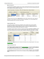
7.4.4.10 Timezone Selection
The Daylight Savings page in the Project Details dialogue allows you to enter the time zone and
Daylight Savings details. This process is simplified by clicking on the Select Other Timezone
button on the Project Details Daylight Savings Tab. This will open the Timezone Selection
dialogue box.
© Copyright 2000-2005 Clipsal Integrated Systems Pty Ltd
Page 31
Intelligent Building Series
Schedule Plus Programmer's Guide
The Timezone Selection dialogue box allows you to select from an extensive list of time zones
supplied by the operating system. There is a list of all Time zones, with the following details :
· GMT : offset from GMT (Greenwich Mean Time)
· Name : the name of the Timezone
· Home : the word "home" is written along side of your home time zone. This can only be changed
from the operating system.
· DLS : this shows whether Daylight Savings is used in this time zone.
· Now : this shows whether Daylight Savings is currently active.
· Date & Time : this shows the current data and time in the time zone
When a time zone is selected, the following details are shown at the bottom of the form :
· Timezone : this is the name of the selected time zone
· Standard Time : this is when Daylight Savings finishes
· Daylight Savings Time : this is when Daylight Savings starts
· Adjustment : this is how much the clocks are adjusted during Daylight Savings time.
Click on the OK button to use the selected time zone for your Project.
Note that the computer timezone can be set using Special Functions. This is the timezone that the
computer is in, and will determine when it changes its time for daylight savings. The project
timezone must match the computer timezone when the project is installed and running. During
development of a project, they may be different (if you are developing a project to run on a
computer in a different timezone).
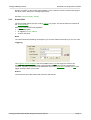
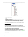
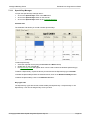
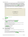
7.4.4.11 Auto Page Creation
The Create Project Pages page in the Project Details dialogue allows you to quickly and
automatically create a series of pages for your project.
© Copyright 2000-2005 Clipsal Integrated Systems Pty Ltd
Page 32
Intelligent Building Series
Schedule Plus Programmer's Guide
The steps in the process are :
· Select the Auto Create button if you want to automatically create pages
· For each page you want to have created, enter the name in the Page Names list
· If you want a menu page created with page links to each page, select the Create Menu item
· If you want each page labelled with its name, select the Label Pages item
· If you want a theme page used for each of your papes, select it from the Theme Page list
· If you want to add a tools page, select the Add Tools Page button, and select the required tools
page from the list, or click the Browse button to select a page which is not listed
· Click on the Finish button when complete
7.4.5
Saving the Project
To save the project, either click on the Save button of the tool bar, or select the Save item from the
File menu. To save the project with a different file name, select Save As from the File menu and
enter the desired name.
If you are saving the project for the first time, or saving with a different file name, you will be
prompted to enter a file name. Select the directory where your project will be stored, and enter a
file name. The default file extension is CTD, which does not need to be entered.
To encrypt the project file to make it secure against tampering, select Secure Project File (*.cte)
from the Save As Type drop down list in the Save As dialogue box.
When you save the project, all associated files (images etc) are copied into the project directory.
This is to ensure that all of the necessary files are collected together to prevent any of them from
being inadvertently deleted, and to simplify archiving the Project . Once the project has been
saved, it will start using the saved files, not the original ones that were selected.
To keep the files for a project together and to prevent them from being confused with files
for other projects, it is recommended that you create a separate directory (folder) for each
project.
To do this, either
· If you are saving the Project file in the recommended \Projects directory, the Schedule Plus
software will ask if you want a separate directory created. This will be created with the same
name as the Project if you click on the Yes button; or
· Create a new folder before you start, using Windows Explorer or similar product; or
· When you save for the first time, or select Save As from the File menu, the Save File dialogue
© Copyright 2000-2005 Clipsal Integrated Systems Pty Ltd
Page 33
Intelligent Building Series
Schedule Plus Programmer's Guide
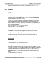
box will appear. If you click on the new folder icon, a new folder will be created. You can then
change the name and select the folder.
New Folder Icon :
To save just the currently displayed page to a file, select Save Page As from the File menu.
Note that when a file is saved, a backup copy is created with the same name, but with a backup file extension.
To save a project as a template, select the Save Template item from the File menu.
See also Saving a Backup
7.4.6
Templates
Templates can be used to store various aspects of a Project which are used on a regular basis. A
Template can store :
· Project Details – all of the information in the Project Details dialogue box.
· Pages, each of which may contain various components
· Theme Pages
· Scenes
· Schedules
· Irrigation Programs
· Special Days
· Access Control
To add a Template page to a project, select the File | Add Template Contents menu item, select
which parts of the Template you want to import using the Template Options form, click OK, select
the Template file and click on OK. If you have used a particular Template before, you can select it
from the File | Re-Add Template Contents menu item.
To save a whole Project as a Template, select the Save As Template item from the File menu,
select which parts of the Project you want to have saved in the Template, click on OK, enter a File
Name and click on OK.
To save just the current page as a Template, select the Save Page As Template item from the
File menu, select which parts of the Project you want to have saved in the Template, click on OK,
enter a File Name and click on OK.
To open an existing Template, select Open Template item from the File menu, select which parts
of the Template you want to import, click OK, select the Template file and click on OK.
Project Templates
© Copyright 2000-2005 Clipsal Integrated Systems Pty Ltd
Page 34
Intelligent Building Series
Schedule Plus Programmer's Guide
Templates can be used to save the user from having to re-enter the same data each time a new
project is started.
To create a project template, follow these steps :
· Create a new Project.
· In the Project Details dialogue box, enter your name and company details.
· In the Project Details dialogue box, enter your location and time zone.
· Create a standard start-up page if you want one.
· Create any other pages that you want to use regularly (you can always delete them later if you
don't use them).
· Place any specific components that you regularly use on a page, so that you can copy and
paste them later.
· Set up any common Scenes that you may need.
· Set up any common Schedules that you may need.
· Set up any Access Levels that you may need.
· Set up the grid to your preferred setting.
· Set any other preferences.
· Select the Save As Template item from the File menu and follow the steps described above.
To use a template in the future, select the Open Template item from the File menu.
Screen Size
When a template with Pages is saved, the Project screen size is also saved. If you load a template
which contains Pages, you have the option to use the template screen size or to keep the screen
size of the Project.
If the Template screen size is different from the Project screen size, a warning will be raised. If the
template page is larger than the Project screen size, then the template Components will be
rearranged so that they fit on the page.
See Tutorial.
7.4.7
Archiving the Project
Archiving consists of collecting together all files related to a Project and compressing them into a
single compact file.
When a Project is complete, installed and tested, you should consider archiving the project files.
The purpose of archiving the files is so that if (when) you need to make changes at a later date, the
files are guaranteed to be available. If you keep the files on your hard disk, and there is a failure,
you may lose many hours of work if you have to re-create the project again.
Ideally, a copy of the archive file should be given to the customer for safe keeping.
See also Saving the Project
7.4.7.1
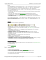
Exporting to an Archive
A new archive is created by the File | Archive | Export to Archive menu selection. This starts the
Archive Wizard which guides the user through the creation of an archive. The first page of the
wizard specifies the project files to archive.
© Copyright 2000-2005 Clipsal Integrated Systems Pty Ltd
Page 35
Intelligent Building Series
Schedule Plus Programmer's Guide
The files specific to the project may be archived. This is a convenient way to extract just the files
used by a project from a directory which contains several projects. Alternatively all files in the
directory or even those included in subdirectories can be specified.
Click on the Next button.
The next dialogue asks for the C-Bus Project used by the Schedule Plus Project.
Select the C-Bus Project file (in the C-Gate\Tag directory) if the dislayed one is incorrect.
Click on the Next button.
If you use a non-standard font (i.e. One which does not come with Windows), it would be advisable
to save a copy of the font with the project. Copy the fonts to the directory requested by the archive
wizard. The font files, which have either a "ttf" or "fon" extension usually reside on the
Windows\Fonts directory or the Winnt40\Fonts on some versions of Windows. Normally, these
fonts would be those which have been downloaded specially for use in the project.
© Copyright 2000-2005 Clipsal Integrated Systems Pty Ltd
Page 36
Intelligent Building Series
Schedule Plus Programmer's Guide
Click on the Next button.
Once all the files have been specified, the archive file is named. The extension for Schedule Plus
software archive files is "cta".
Click on the Finish button.
7.4.7.2
Importing from an Archive
To open an archive, select the File | Archive | Import From Archive menu item. This starts the
Import Archive wizard. The first page in the Wizard asks for the archive to load.
Click on the Next button.
The restore files page selects where the files will be restored to.
© Copyright 2000-2005 Clipsal Integrated Systems Pty Ltd
Page 37
Intelligent Building Series
Schedule Plus Programmer's Guide
Click on the Next button.
The C-Bus Project is imported next. The xml file has to be copied into the C-Gate\tag directory. If
the C-Bus Project file or the C-Gate tag directory is incorrect, enter the correct values. If you want
to manually copy the tag file later, de-select the Copy C-Bus Project check box.
Click on the Next button.
Finally, any fonts which might have been saved are restored to the Project Directory. They then
need to be manually copied into the Windows Fonts directory for Windows to use them.
Click on the Finish button. The project is restored to the selected directory and the user is offered
the option of opening up the newly restored project.
7.4.7.3
Saving a Backup
It can be a good idea to save a backup copy of your Project at various phases of development.
This will allow you to go back to a particular version of the Project in case you should change your
mind about changes you have made to the Project.
To save a backup of the Project, select the File | Archive | Save Backup menu item. This will
save a copy of the project with the date and time included in the file name, which guarantees that
each backup file will have a unique, identifiable name.
7.4.8
Printing
This software does not support printing directly, but it is quite simple to print out most things that
may be of interest.
© Copyright 2000-2005 Clipsal Integrated Systems Pty Ltd
Page 38
Intelligent Building Series
Schedule Plus Programmer's Guide
To print out any of the following details :
· Project Details (installer, location etc)
· Schedules
· Scenes
· Network, Application and Group Address usage
· Images used
· Access Control details
· Irrigation Control details
create a Project Summary file (it can be set to HTML or plain text in the Project Details) which can
then be printed directly.
To print screen shots, save the Screen Image(s). Open the file(s) with an image manipulation
program and print from there.
To print the log, open the log file with a suitable program (text editor, spreadsheet or database) and
print from there.
To print the details of the Load Monitor, open the Load Monitor data file with a database or
spreadsheet program and print from there.
7.4.9
Time-Out
You may wish the software to display a particular page after the Schedule Plus software has not
been used for some time. The time-out page and the duration of the time-out period can be set in
the Project Details dialogue box. When the time-out period expires, any logged-in user will be
logged out and the time-out page will be displayed.
Each Page can also have its time-out duration set independently if required. Pages which allow
access to more critical functions should have a shorter time-out set.
7.5
Pages
A page is a set of components that are displayed together. A Project may contain many pages
linked together so that user can navigate between them.
See also Good Design Practices
7.5.1
Selecting Pages
To select a particular page, either :
· Select the required page from the drop down list on the tool bar
· If the required page has a link from the current page, activate the component that links to it.
· Use the CTRL + Page Up/Down keys to move forward or back a page
7.5.2
Adding Pages
A project can have multiple pages, each of which contains various components.
To add a new page :
· click on the New Page speed button on the Tool Bar OR select the Page sub-menu from the
Edit menu, then select the New Page item
· enter the name of the new page
· click on OK
To make a copy of a page :
· Select the desired page
· select the Page sub-menu from the Edit menu, then select the Duplicate Page item
· enter the name of the new page
· click on OK
© Copyright 2000-2005 Clipsal Integrated Systems Pty Ltd
Page 39
Intelligent Building Series
Schedule Plus Programmer's Guide
To add a Template page (or pages) with its components to the current project, either
· select the Add Template Page(s) item from the Edit menu;
· select which parts of the Template you want to load
· select the desired file
· click on OK
· if the name of the Template page has already been used, a new one will be assigned
7.5.3
Deleting Pages
To delete a page :
· Select the desired page
· select the Page sub-menu from the Edit menu, then select the Delete Page item
· click on OK
All components on the page will be deleted. Any Component page links will be automatically
adjusted.
7.5.4
Page Properties
To change the properties of the currently displayed page, either :
· Select the Page Properties item from the Edit menu; or
· Double click on the page where there are no components
A dialogue box will appear which will enable the user to change :
· The name of the page
· The Access Level for the page
· The Theme for the page
· The background style :
· Single Colour
· Colour gradient from left to right (blend between two colours)
· Colour gradient from top to bottom
· Centred image (image is drawn in the centre of the window)
· Tiled image (image is drawn many times to fill the window)
· Stretched image (image is stretched to fill the window)
· The background colour(s) (if applicable)
· The background image (if applicable)
· The Time-out duration for the page
© Copyright 2000-2005 Clipsal Integrated Systems Pty Ltd
Page 40
Intelligent Building Series
Schedule Plus Programmer's Guide
If an Access Level has been set for a page, then when the user tries to select that page, they will
have to Log-in to get access to that page.
After a certain time of displaying a page, it will time-out and select the Time-Out page. The Page
time-out duration can be set to :
· Project Default - use the time-out duration set in the Project Details
· Never time-out - this is useful if an alarm or message page has been displayed
· Other time - enter the time required
Note :
The Start-up and Time-out page(s) must always have the lowest Access Level, otherwise you will
not be able to open a project.
If a Theme is selected, the Page Background settings will be ignored.
7.6
Components
A Component is an item that can be placed on a page. It may be a button, text, image, clock,
slider, monitor or other type of component. Components can be used to display information,
control C-Bus or to navigate the Project pages.
See also Good Design Practices
7.6.1
Component Actions
When a component is activated, it can perform an action.
The types of Actions which a component can perform include :
· Selecting another page;
· Executing a C-Bus command
· Execute a Special Function; or
© Copyright 2000-2005 Clipsal Integrated Systems Pty Ltd
Page 41
Intelligent Building Series
Schedule Plus Programmer's Guide
Components do not have to have an Action. They can be used purely for visual effect, or to display
some sort of data.
7.6.2
Activating Components
Activating a Components causes it to perform the action which it is intended to do.
To activate a component on the Schedule Plus Software, right mouse click on the component. If
Schedule Plus is running on a Touch Panel PC and it is running in Operation Mode, pressing a
component with your finger will activate it.
Note that the component which is on top will be the one activated. Any components which have no
action when pressed will be ignored when determining which component to activate. For example,
in the example below, there is a button controlling C-Bus with an image on top of the button, and
another button controlling C-Bus with a C-Bus Timer Display on top.
If the user clicks on the image of the car, then the image will be ignored (assuming that there are
no actions associated with it), and the "click" will go through to the component below (the button).
In a similar way, if the user clicks on the C-Bus Timer Display, it too will be ignored because its CBus action is "status" and hence it performs no action.
Note that when a Component is activated, its status indicator will change immediately, but there
may be a delay in the command being executed on C-Bus.
See also Program Options and Remote Control
7.6.3
Component Types
There are only a few basic types of Components, but they can have their properties set to make
them look like there are in fact hundreds of types :
· Text
· Images
· Shapes
· Buttons
· Sliders
· Level Indicators
· Clocks
· Monitors
All components have the following properties in common :
· all components may have an Action
· all components may have their Remote Control properties set
· all components have a Position and Size
7.6.3.1
Text
This displays one or more lines of text. The font can be set. There is no border or background.
Examples :
© Copyright 2000-2005 Clipsal Integrated Systems Pty Ltd
Page 42
Intelligent Building Series
7.6.3.2
Schedule Plus Programmer's Guide
Images
An Image Component displays a bitmap, JPEG or WMF image on the page.
A bitmap image can be set to be transparent if desired. In this case, the colour of the bottom left
pixel will be used as the transparent colour. Any pixels in the image matching this colour will not be
displayed (i.e. will be transparent).
An image has no border or background. When the Project is Saved, all images are copied to the
project directory. If an image that is used by the project is deleted or renamed, an error message
will be raised and a "dummy" image will be displayed.
The image is limited to the size of the screen.
Images can be stretched in the Schedule Plus software, but it may be preferable to use an image
manipulation program to perform this before placing the image on a Page.
7.6.3.3
Shapes
A Shape Component has a border and background and nothing else. It can be used for displaying
:
· Rectangles
· Horizontal or vertical lines (ie. very narrow rectangles)
· Triangles
· Circles and Ellipses
· Pointers
· Invisible "hot spots: which can be activated
Examples :
7.6.3.4
Note : when placing a Shape, the border shape can be selected from a drop-down list on the
Tool Bar.
Buttons
A Button Component consists of a border, background, text and an image. All of these parts can
be used to indicate C-Bus status :
· The border and background can change colour according the Group Address level.
· The text words and font can change according the Group Address state.
· The image can toggle between any two images to indicate the Group Address state.
Examples :
© Copyright 2000-2005 Clipsal Integrated Systems Pty Ltd
Page 43
Intelligent Building Series
7.6.3.5
Schedule Plus Programmer's Guide
Sliders
A Slider Component is used to set or show the precise level of a Group.
A slider can be either a normal slider or a bar graph.
A Slider consists of a border, background, slot, thumb (the bit that slides up and down or left and
right) and tick marks (the lines along the side). The Slider thumb is used to set or indicate the CBus Level. For example, if the thumb is 80% of the way from the bottom (or left, if it is a horizontal
slider), then the Group Address Level is 80%.
Examples :
7.6.3.6
Level Indicators
A Level Indicator Component is used to show the precise level of a group. It has a border and
background and can have its text font set.
The options for the level display are :
· as a percentage of full load
· as a Level (0 to 255)
· as an RCS (Room Control System) Temperature (if the Group Address is used to broadcast
RCS Temperature)
· as a Tag Description (if there are Level Tags for the Group)
Examples :
7.6.3.7
Clocks
A Clock Component is used to show the time, day of the week and/or date. It has a border and
background and can have its text font set. A Clock Component can also display :
· the amount of time remaining on a C-Bus timer
· sunrise time
© Copyright 2000-2005 Clipsal Integrated Systems Pty Ltd
Page 44
Intelligent Building Series
·
·
·
Schedule Plus Programmer's Guide
sunset time
the Irrigation Controller timer
a Schedule Time
Examples :
7.6.3.8
Monitors
A monitor component is like a gauge that can display the value of some variable. A monitor can be
used to display temperature, light levels or voltage. It has a border and background and can have
its text font set.
Examples :
7.6.3.9
Selectors
A Selector component is used to allow the selection of an item from a list, in much the same way
as a Windows "Radio Group".
A Selector Component consists of a border, background, text and an image. All of these parts can
be used to indicate C-Bus status :
· The border and background can change colour according the Group Address level.
· The text font can change according the selected item.
· The image can toggle between any two images to indicate the selected item.
· The selected item in the list indicates the current Group Address level.
Example :
The first item in the list will be selected when the Group Address Level is 0. The second item will
be selected when the level is 1 and so on.
When setting the Selector properties, add one line of Text for each option you want in the list.
7.6.3.10 HTML
An HTML Component consists of a border and an HTML (web) page.
The HTML Component can be used to show any HTML page, including :
· pages on the hard disk (for example, instructions)
· web pages (for example, a weather forecast)
· video camera images
© Copyright 2000-2005 Clipsal Integrated Systems Pty Ltd
Page 45
Intelligent Building Series
Schedule Plus Programmer's Guide
· web based control panels
The properties which can be selected for an HTML Component are :
· Border
· URL (web address)
· Refresh Rate
The refresh rate can be set if the page needs to be refreshed on a regular basis.
The HTML Component is unique in several respects :
· The user can only click on the Border to Select or Manipulate it
· The Background is not drawn by the Schedule Plus software, but by the operating system and is
always on top of the Drawing Order
· The background image will not appear if using Internet Access
Note that if an Internet page is to be displayed, the computer running Schedule Plus needs to have
an Internet connection. It is recommended that a firewall and virus scanner are used for security.
7.6.4
Component Properties
To change the properties of a particular Component, either :
· Double click on the component; or
· Select the component (by clicking on it) and select the Component Properties item in the
Edit menu.
A dialogue box will appear that will enable the user to change the Component's :
· Physical appearance
· Page Links
· Special Functions
· Remote Control
· C-Bus Properties
· System IO Properties
· Status Indication Options
It is possible to have the Component Properties editor appear automatically when a Component is
placed by selecting the option in the Program Options.
7.6.4.1
See also Good Design Practices
Visible Properties
To change the visible properties (physical appearance) of a particular Component, open the
Component Properties form then select the Visible Properties tab. The options on the Visible
Properties tab depend upon the type of component, and may include :
© Copyright 2000-2005 Clipsal Integrated Systems Pty Ltd
Page 46
Intelligent Building Series
Schedule Plus Programmer's Guide
· Position
· Border
· Background
· Text
· Image
· Clocks
· Slider
· Monitor
· Value
7.6.4.1.1 Position
The Position tab of the Visible Properties tab allows the size and position of the component to be
entered manually. The position is specified by the coordinate of the left and top corner of the
rectangle bounding the component and the width and height of the component.
When a triangular, round or oval shaped component is placed on a page, the component is
bounded by an imaginary rectangle. The coordinates on this tab refer to this bounding rectangle.
7.6.4.1.2 Border
The border of a component is the shape and style of the outline of the component.
The Border tab of the Visible Properties tab allows you to enter the appearance of the border of
the component. You can select the following border properties :
· shape (rectangle, ellipse, triangle etc.)
· line style (solid, dotted, raised, lowered etc.)
· border width
· colour
· Alpha Blending
© Copyright 2000-2005 Clipsal Integrated Systems Pty Ltd
Page 47
Intelligent Building Series
Schedule Plus Programmer's Guide
The border shape may be :
· Rectangle
· Rounded Rectangle
· Triangle
· Circle / ellipse
· Pointer
· Capsule
· Polygon
· Star
Some of the possible border shapes are shown below.
© Copyright 2000-2005 Clipsal Integrated Systems Pty Ltd
Page 48
Intelligent Building Series
Schedule Plus Programmer's Guide
The available border style options depend on the border shape. The options are :
· none (this will make the border transparent, in which case it will not be seen)
· a solid line of different thicknesses
· a dotted line (border width must be 1)
· a dashed line (border width must be 1)
· a double line
· raised
· lowered
· raised edge
· lowered edge
Border Lines Styes are shown below :
© Copyright 2000-2005 Clipsal Integrated Systems Pty Ltd
Page 49
Intelligent Building Series
Schedule Plus Programmer's Guide
The border Colour can also be selected.
If the border colour or style is to change to show the status of the Component, the Border Status
Indication check box is ticked and the active and inactive styles and colours are both selected.
The colours can be chosen from a palette or specified by hue, saturation and luminance. The
colour status indication is selected from a palette in the same way for both the border and the
background.
Colour blending is the process of mixing two colours together to yield an intermediate colour.
Ticking the Colour Blending tick box will allow an indicator or component to display different
colours between minimum and maximum. The two endpoint colours must be selected for this to
work.
Note that if a colour and the complement of that colour are mixed together the result is a neutral
grey. So the combination of blue and yellow, red and cyan or green and magenta will be neutral
grey in a 50/50 mix (ie. when the level is at 50%).
Conversely, two colours which are not complements such as red and green (two of the additive
primary colours) will yield some kind of colour at all ratios. Hence, for an indicator to show as
coloured at all settings the two end points should not be complements of each other.
If you click the Copy Colour To Background button, the active and inactive Border colours will be
copied to the active and inactive Background colours.
7.6.4.1.3 Background
The background of a Component is the style used to "paint" the component inside the border.
The Background tab of the Visible Properties tab allows you to enter the appearance of the
background of the component. The following properties can be set :
· Background Colour
· Background Style (none, solid, stripes etc)
· Alpha Blending
The background style may be set to :
· None (this will make it transparent)
· Solid (i.e. a plain colour)
· Light Shaded
· Medium Shaded
· Dark Shaded
· Back Diagonal
· Forward Diagonal
· Cross
© Copyright 2000-2005 Clipsal Integrated Systems Pty Ltd
Page 50
Intelligent Building Series
Schedule Plus Programmer's Guide
· Diagonal Cross
· Horizontal
· Vertical
Note that if the shading is set to Light, Medium or Dark Shaded, the colour can only be black. For
the other shading options, it can be any colour on a transparent background.
The possible background styles are shown below :
If you wish to have the background style or colour change to show the status of the Component,
click on the Background Status Indication check box and select both the active and inactive
background colours. If the Colour Blending option is selected, the colour will change from one
colour to the other gradually as the Group Address level changes.
If you click the Copy Colour To Border button, the active and inactive Background colours will be
copied to the active and inactive Border colours.
7.6.4.1.4 Alpha Blending
Alpha Blending is the process of making something look translucent (ie. you can partly see through
it). A component Border and Background can have an amount of alpha blending selected (they
both use the same amount).
The amount of blending can be from 0% (all component, no background) to 100% (all background,
component is invisible) :
7.6.4.1.5 Text
The Text tab of the Visible Properties tab allows you to set the component text, the text alignment
(top, left, centre etc) and the text font.
© Copyright 2000-2005 Clipsal Integrated Systems Pty Ltd
Page 51
Intelligent Building Series
Schedule Plus Programmer's Guide
To select the font, click on the Set Font button and the Font Selection dialogue will appear.
To set the text alignment (top, left, centre etc), click on one of the Text Alignment buttons.
If you wish to have the text and/or font style change to show the status of the associated C-Bus
group address, click on the Font Status Indication check box and select the active and inactive
text and fonts.
You can insert symbols into the text boxes as follows :
1. Select the required font
2. Select the position where you want the symbol inserted
3. Right click on the text box and select the Insert Symbol item
4. The Insert Symbol dialogue will appear.
4. Click on the desired symbols (they will appear at the top of the dialogue box)
5. Click on OK
For Clocks, Level Indicators and Monitors, a sample of the text is displayed. The actual text
displayed will depend on the actual value of the data displayed.
7.6.4.1.6 Image
The Images tab of the Visible Properties tab allows you to select which image(s) are displayed on
a button, Selector or Image component and the image alignment (top, left, centre etc).
© Copyright 2000-2005 Clipsal Integrated Systems Pty Ltd
Page 52
Intelligent Building Series
Schedule Plus Programmer's Guide
To display an image, select the Show Image check box. Either :
· select one of the standard images; or
· click on the Custom button and select your own active and inactive images by clicking on the
Select Active Image and Select Inactive Image buttons. A dialogue box will appear, allowing
you to select a bitmap, JPEG or WMF image.
A bitmap image can be made transparent by selecting the Transparent Image check box. The
colour of the bottom left pixel will be used as the transparent colour. Any pixels in the image
matching this colour will not be displayed (ie. will be transparent)., A JPEG or WMF image can not
be made transparent.
Animated Images
Animated images in the form of bitmap strips can be displayed. A bitmap strip has a seies of
"frames" in the bitmap. These get displayed one after the other to give an animation effect. A text
file with the same name as the bitmap is used to provide the details of the animation. Refer to the
provided sample animated images to get a better understanding of how these work.
Button components can also select a frame of a bitmap depending on the C-Bus level. This allows
almost any customised effect to be created to display the level of a C-Bus Group Address. To do
this, select an animated image as the Active Image. Select the Select Frame Using Level check
box. The number of frames in the bitmap will be divided across the range 0 to 255. Hence if there
are 10 frames, the first will be shown for levels 0 to 25 (255 / 10), the second from 26 to 51 and so
on.
There are various shareware programs available for converting animated GIF images into bitmap
strips including Alchemy GIF Animator.
Note that once you load an image into a Project, it will remain the same until it is re-loaded. If you
edit the file on disk, you will not see the new image on the screen unless you open the Project
again, or use the Options | Refresh Images menu item.
7.6.4.1.7 Clock
The Clock tab of the Visible Properties tab allows you to set the properties of a clock component.
© Copyright 2000-2005 Clipsal Integrated Systems Pty Ltd
Page 53
Intelligent Building Series
Schedule Plus Programmer's Guide
There are several options for the time information which will be displayed. The Time / Date
Displayed drop down list allows the following types to be selected :
· Current Time/Date – this displays the current time and/or date.
· Sunrise Time – this displays today's sunrise time
· Sunset Time – this displays today's sunset time
· Schedule Time – this shows the due time for the schedule in the adjacent drop-down list.
· C-Bus Timer – this shows the remaining time left on the timer for the associated
Group Address
· Irrigation Timer – this displays the amount of time left in the current Irrigation Zone (if irrigation
is running).
· System IO Time - this displays the value of the associated System IO variable
· Logic Timer Time - this displays the time of the selected Logic Timer
If displaying the current time/date, you can select :
· whether seconds are displayed
· whether 24 hour format is used or AM/PM
If displaying the day of the week, you can select whether the full or abbreviated day name is used
If displaying the date, you can select :
· Date order
· DD/MM/YY (Day / Month / Year)
· MM/DD/YY (Month / Day / Year)
· YY/MM/DD (Year / Month / Day)
· 2 or 4 digit year
· Month number or name
· Whether the separator (/) is used
A sample of the time/date is displayed at the bottom in the format selected.
7.6.4.1.8 Slider
The Slider tab of the Visible Properties tab allows you set the appearance of a slider component.
A Slider consists of a border, background, slot, thumb (the bit that slides up and down) and tick
marks (the lines along the side). The Slider thumb is used to set or indicate the C-Bus Level.
© Copyright 2000-2005 Clipsal Integrated Systems Pty Ltd
Page 54
Intelligent Building Series
Schedule Plus Programmer's Guide
You can set the following slider details :
· Orientation
· Vertical
· Horizontal
· Style
· A Slider has a thumb (the bit that slides up and down)
· A Bar has a rectangle of colour to indicate the C-Bus Level.
· Appearance of the slot
· Shape
· Border Style
· Border Width
· Slot width
· Border Colour
· Background Colour
· Appearance of the thumb (if it is a Slider Style)
· Shape
· Border Style
· Border Width
· Thumb Width
· Thumb Length
· Border Colour
· Background Colour
· The tick marks
· Style (none, one side or both sides)
· Colour
· Width
· Length
· The Bar Colour (if it is a Bar Style)
· Active Colour
· Inactive Colour
· The colour blending can be used to change the colour of the bar as the C-Bus level
changes.
© Copyright 2000-2005 Clipsal Integrated Systems Pty Ltd
Page 55
Intelligent Building Series
Schedule Plus Programmer's Guide
7.6.4.1.9 Monitor
The Monitor tab of the Visible Properties tab allows you to set the properties of a Monitor
Component.
You must select :
· the type of data displayed (temperature, light level or voltage)
· the Network which the unit is installed on
· the unit address of the C-Bus device that is having its data read (use the C-Bus Tool Kit to
determine this)
· the refresh (update) rate
· the data accuracy (precision)
The readings displayed can be updated at different intervals. The time between updates of the
display may range from 20 to 255 seconds. A short refresh interval would load the C-Bus Network
with commands to a greater extent than a long interval. Unless the information has to be very
current, the longer times should be used.
7.6.4.1.10 Value
The Value tab of the Visible Properties tab allows you to set the properties of a Level Indicator
Component.
© Copyright 2000-2005 Clipsal Integrated Systems Pty Ltd
Page 56
Intelligent Building Series
Schedule Plus Programmer's Guide
For a Component controlling C-Bus, the options are :
· C-Bus Group Address Percent : display Group level as a percentage of full load
· C-Bus Group Address Level : display Group level
· C-Bus Group Address RCS Temperature : display Group level as an RCS (Room Control
System) Temperature (if the Group Address is used to broadcast RCS Temperature)
· C-Bus Group Address Level Tag Description : display Group level as a Tag Description (if
there are Level Tags for the Group)
· C-Bus Group Address Tag Description : display Group tag
· C-Bus Group Address Custom : : display Group level as a custom value (see below)
Custom Format
When displaying a value using the custom option, there are several properties which can be
selected to control the text displayed :
· Prefix Text : this is text displayed before the numerical value
· Postfix Text : this is text displayed after the numerical value
· Gain : this is used to scale the value displayed (see below)
· Offset : this is used to scale the value displayed (see below)
· Decimal Places : this controls the accuracy of the number displayed
Value Scaling
Sometimes it is necessary to change the value which is displayed. For example, you may have a
temperature sensor connected to an analogue input unit which is broadcasting the value on a
Group Address. In these cases, it is necessary to scale the value. There are two parameters which
are used to implement the scaling. The "gain" is multiplied by the value and the "offset" is added to
the value to get the result which is displayed. For example, with a gain of 2 and an offset of 10, the
relationship between the level and the result displayed would be :
© Copyright 2000-2005 Clipsal Integrated Systems Pty Ltd
Page 57
Intelligent Building Series
Schedule Plus Programmer's Guide
Level
Result = 2 * Level + 10
0
10
1
12
2
14
100
210
255
520
If you do not want to use scaling, have the gain = 1 and the offset = 0.
Calculating Scaling Coefficients
To calculate the necessary gain and offset values, click on the Calculate button. Enter the result
you want displayed when the C-Bus level is at its minimum and click OK. Enter the result you want
displayed when the level is at its maximum and click OK. The gain and offset will be calculated and
placed in the boxes for you.
Alternatively, the scaling coefficients can be calculated by knowing what the result is for two
different levels. If the levels are X1 and X2 and the corresponding results are Y1 and Y2
respectively, then
Gain = (Y2 - Y1) / (X2 - X1)
Offset = Y1 - Gain * X1
Note : The Room Control System is an obsolete system for which support has been retained for
backwards compatibility.
7.6.4.1.11 Status
The status of a Component refers to whether the function being controlled by the Component is
Active (on) or not. The functions which can be indicated by the Component's status include :
· C-Bus Group Address Level (on or off)
· C-Bus Scene state (set or not set)
· C-Bus Timer (running or not running)
· Click (whether the Component is being clicked by the user or not)
· Page Link (whether the page linked to is currently being displayed - useful for Theme Pages with
menu bars)
The status of a Component can be displayed by a variety of means, depending on the
Component Type :
· Border
· Background
· Images
· Text
To select which function controls the Component's status, select the Status tab on the
Component Properties dialogue :
© Copyright 2000-2005 Clipsal Integrated Systems Pty Ltd
Page 58
Intelligent Building Series
Schedule Plus Programmer's Guide
If the Automatic option is selected, then the status will indicate :
· the C-Bus level if the Component controls C-Bus; or
· the System IO level if the Component controls a System IO variable; or
· the click state if the Component controls something else
C-Bus Indicator
The C-Bus Indicator Range group of the status tab allows you to select how the C-Bus state
indication will be related to the C-Bus Group Address Level.
By default, it will show the Inactive state of the button when the C-Bus level is 0 and the Active
state of the button for any other C-Bus level. There are circumstances where this behaviour may
need to be changed. The options which are able to be selected are :
· Default – when this is selected the default behaviour is used.
· Preset Level – when this is selected and the button is a PRESET or STATUS button (see
above), the Active state will be shown if the C-Bus level equals the selected level (on the Key
Functions Tab), otherwise the Inactive state will be displayed.
· Custom Levels – when this is selected, the minimum and maximum levels can be selected for
which the Active state will be shown. For all other levels outside of this range, the Inactive state
will be shown.
· Scene Indicator - when this is selected, the status will show when the Scene is set (ie. the
levels of the Group Addresses in the Scene all match the levels of the Scene)
Note : If the Component is controlling the groups in a Scene (other than just setting the
Scene), the first Group Address in the scene will be used for showing the status.
7.6.4.2
C-Bus Properties
To set the C-Bus properties of a component :
· Open the Component Properties form
· Select the C-Bus tab
· Select the C-Bus type (key function)
· Select the Controlled Item (Scene or Group Address)
· Select the Other Properties (Level, Ramp Rate, Pulse Duration)
· Select the Indicator Functions
Alternatively, the Group Address of one component can be copied to other components as follows :
· Select the component to have its Group Address copied
· Select the other components to have the Group Address copied to
· Select the Edit | Copy Group menu item (or use CTRL + G)
© Copyright 2000-2005 Clipsal Integrated Systems Pty Ltd
Page 59
Intelligent Building Series
Schedule Plus Programmer's Guide
7.6.4.2.1 Key Functions
The C-Bus tab allows you to set the C-Bus functionality of the Component.
C-Bus Key Function
The component will behave differently depending on which C-Bus type is selected. The C-Bus
component can be set to any of the following types :
· ON : this switches the load on.
· OFF : this switches the load off.
· ON/OFF : this toggles the load on and off. If the load level is greater than 0%, it is regarded as
being on.
· DIMMER : a short press will toggle the load on and off. A longer press will dim the load up and
down.
· ON/UP : a short press will switch the load on. A longer press will dim the load up.
· OFF/DOWN : a short press will switch the load off. A longer press will dim the load down.
· TIMER : this will switch a load to a particular level for a particular time. When the time expires,
the load will return to a specified level. The timer time can be shown with a Clock component.
· PRESET : this will set the load to a preset level (0-100%).
· PRESS : this will set the load to a particular level while the component is being pressed. When
the component is released, the load will return to a specified level.
· SCENE : This will set a scene. Note that pressing a scene button for more that 10 seconds will
show the Scene Editor dialogue box.
· NUDGE UP : This adjusts the load level up by the amount set in the Level box.
· NUDGE DOWN : This adjusts the load level down by the amount set in the Level box.
· SLIDER : This is used for sliders only.
· STATUS : this will show the C-Bus status, but pressing the component will have no effect.
· UNUSED : this will not show C-Bus status or perform any C-Bus action when pressed.
Note that if C-Bus Remote Control is selected, only the Status option is available.
Controlled Item
If you wish for the Component to adjust all of the Group Addresses in a Scene, select the Scene
Groups button and select the desired Scene.
© Copyright 2000-2005 Clipsal Integrated Systems Pty Ltd
Page 60
Intelligent Building Series
Schedule Plus Programmer's Guide
If you wish to control a Single Group Address then :
· Select the Single Group button
· Select the network
· Select the Application Number
· Select the Group Address
Level
If the component is to be a preset, press, timer, nudge up or nudge down you will need to select
the Level. You can either select a particular level in percent or a tag. If you are connected to CBus, you can also use the current level of the Group Address.
Ramp Rate
If the component is to be a preset, press, timer, nudge up or nudge down you will need to select
the Ramp Rate. Select a rate at which the Group Address level is to change.
Pulse
If the component is a timer, you will need to select the timer duration and type. A toggle timer will
start when it is pressed, then stop after the time-out period, or if the timer is pressed again before it
has timed out. A re-settable timer will start the timer again if pressed before the timer has expired.
Note that a clock component can be used to display the amount of time left on a timer.
If the component is a press button or a timer, you need to select the level to which the Group
Address is to return to when the press button is released or the timer expires.
7.6.4.3
System IO Properties
System IO variables are used by the Logic Engine to provide monitoring and control of the Logic
Engine. A Component can control or monitor a System IO Variable in a similar way to controlling
C-Bus.
To change the System IO properties of a particular Component, open the Component Properties
form then select the System IO tab :
The Key Function list allows the function to be selected, with the following options :
· UNUSED : this will not show System IO Variable status or perform any System IO Variable
action when pressed.
· ON : this switches the System IO Variable to its maximum value.
· OFF : this switches the System IO Variable to its minimum value.
· ON/OFF : this toggles the System IO Variable between its minimum and maximum value.
· PRESET : this will set the System IO Variable to a preset level.
· NUDGE UP : this adjusts the System IO Variable level up by the amount set in the Value box.
· NUDGE DOWN : This adjusts the System IO Variable level down by the amount set in the
© Copyright 2000-2005 Clipsal Integrated Systems Pty Ltd
Page 61
Intelligent Building Series
·
·
·
·
·
·
·
·
Schedule Plus Programmer's Guide
Value box.
SLIDER : this is used for System IO Variable sliders only.
STATUS : this will show the System IO Variable status, but pressing the component will have
no effect.
SELECTOR : this is used for System IO Variable Selectors only.
BELL PRESS : this sets the System IO Variable to its maximum while the component is held,
then sets it to the minimum value when released.
INCREMENT MONTH : this increments (increases by one) the month (date System I/O only)
DECREMENT MONTH : this decrements (decreases by one) the month (date System I/O only)
INCREMENT YEAR : this increments (increases by one) the year (date System I/O only)
DECREMENT YEAR : this decrements (decreases by one) the year (date System I/O only)
The Variable list allows the System IO Variable to be selected.
The Add / Edit button allows System IO Variables to be edited or new System IO Variables to be
created.
7.6.4.4
Special Functions
When a component is activated, it can cause some "Special Functions" to be executed. Some
Special Functions can also be executed by Schedules.
Special Functions include :
· None : no Special Function is used
· Access Control Edit - Open the Access Control Manager
· Alarm On – this starts an alarm
· Alarm Off – this stops the alarm
· Alarm Snooze – this delays the alarm for a set amount of time
· Cleaning Mode - this disables the touch screen so that it can be cleaned
· Date / Time Set - Set the computer Date, Time and Timezone
· Display Properties - Set the computer Display (screen saver etc)
· Help Show - this opens the help file
· Internet Setup - Set the computer Internet properties
· Irrigation Edit - Open the Irrigation Manager
· Irrigation, Run Zone - Run an Irrigation Zone (manual control)
· Load Monitor Show - Show Load Monitor
· Log Show - Show Log
· Logic Edit - show the Logic Editor
· Log-in - this shows the log-in page
· Log-out - this logs the user out and returns to the start-up page
· Module Disable - disable a Logic Module to stop it from running
· Module Enable - enable a Logic Module
· Networking Setup - Set the computer networking properties
· Operation Mode Enter - start Operation Mode
· Operation Mode Exit - stop Operation Mode
· Password Edit - edit the user password
· Program Exit - Exit Program – this closes the Schedule Plus program (can also use Alt + F4)
· Program Minimise - minimise the Schedule Plus program
· Program Run - run a Program
· Project Save File - save the Project file
· Region/language - Set the computer Region (date/time formats etc)
· Scene Edit - If All Scenes is selected then the Scene Manager will be opened. If Specific
Scene is selected, then the selected scene will be opened.
· Scene Store - store the current settings for the selected Scene
· Schedule Edit - If All Schedules is selected then the Schedule Manager will be opened. If
Specific Schedule is selected, then the selected schedule will be opened.
· Schedule Synchronise - Synchronise to Schedules
© Copyright 2000-2005 Clipsal Integrated Systems Pty Ltd
Page 62
Intelligent Building Series
·
·
·
·
Schedule Plus Programmer's Guide
Sound Set - Set the computer Sound
Special Day Edit - Open the Special Days Manager
System IO Edit - if All System IO is selected, then the System IO Manager will be opened. If
Specific System IO is selected then the selected System IO Variable will be opened.
System Properties - Show the computer system information (processor, memory etc)
Note that most Special Functions can not be accessed via the Internet.
To add a Special Function to a component :
· Open the Component Properties form
· Select the Special Function tab
· Select the special function from the list
· Enter any other information applicable to that special function (Schedule Number, Scene
Number, Irrigation Zone, Program Details, Module Number, System IO Variable)
See also Tool Select
7.6.4.5
Page Links
When a component is activated, it can cause another page to be displayed. To do this, a link to the
page needs to be added to the component.
To add a link :
· Open the Component Properties form then
· Select the Page Link tab page
· Select the destination page from the list
Links can be either to any user created page, or to the previous page. To create a "back" button
which takes you back to the previous page :
· select the Special Page button
· select the Back item in the list
Alternatively, you can use the Tool Select to place a "back" button.
© Copyright 2000-2005 Clipsal Integrated Systems Pty Ltd
Page 63
Intelligent Building Series
7.6.4.6
Schedule Plus Programmer's Guide
Remote Control
A Component can be Activated by means of a C-Bus event.
To do this, open the Component Properties dialogue, and select the Remote Control tab :
The C-Bus Group Address to be used to activate the Component is selected on the C-Bus tab of
the Component Properties dialogue box.
To activate the component for this Group Address being set to any level, select the Remote
Control for any C-Bus Level button. To activate the Component only if the Group Address is set
to a particular level (as set on the C-Bus Tab), select the Remote Control if C-Bus Level
Matches button.
Note : if a Component is activated by a C-Bus Group, it can not also be used to control a CBus Group.
A component can only be remote controlled if the page it is on is showing. To enable a Component
to be remote controlled regardless of which page is showing, place the Component on a
Theme Page and use that Theme Page for all of your other pages in the project. This will ensure
that the Component is always available without having to copy it to every page.
7.6.4.7
Inserting Symbols in Text
Each Font has many characters (symbols) apart from the letters of the alphabet, and the numbers,
such as © µ ¥ etc. Many of these symbols do not have a corresponding key on a standard
keyboard.
When editing the text of a component, select the position in the text that you want a symbol
inserted. Right click on the text and select the Insert Symbol menu item. A dialogue box appears
which shows all possible symbols in the currently selected font. Click on the symbols that you want
inserted. Click on the OK button to insert the selected symbols.
© Copyright 2000-2005 Clipsal Integrated Systems Pty Ltd
Page 64
Intelligent Building Series
7.6.4.8
Schedule Plus Programmer's Guide
Font Selection
Fonts can be selected by means of the Font Selection dialogue box. A list of fonts shows all of the
fonts currently used in the project, with the currently selected font highlighted. A sample of the font
is also displayed.
To change to another font which is in the list, just click on the desired font. If you wish to use a
different font, click on the Select Other Fonts button and select the required font.
The default font can be set so that all components which are placed will use this font. To set the
default font, select the Default Font item from the Options Menu or use the button on the tool bar.
NOTES :
The font selection dialogue box is used to minimise the number of different fonts which are used in
a project because projects look much better with a minimal number of different fonts used –
consistency makes it easier to understand.
© Copyright 2000-2005 Clipsal Integrated Systems Pty Ltd
Page 65
Intelligent Building Series
7.6.4.9
Schedule Plus Programmer's Guide
See also Good Design Practices.
Colours
The colour of various things can be set to almost any colour desired :
· Page background colour
· Component background and border
· Slider thumb, slot and tick marks
Colours are selected using the Colour form. You can either select a Basic Colour by clicking on the
desired colour or you can select a Custom Colour.
Selecting Custom Colours
Select the shade required by clicking on the colour square :
Then click on the desired intensity for the colour :
Then click on the Add to Custom Colors button to add the colour to the Custom colors list.
© Copyright 2000-2005 Clipsal Integrated Systems Pty Ltd
Page 66
Intelligent Building Series
Schedule Plus Programmer's Guide
Click on OK to use the colour..
To copy a custom colour from one object (component or page) to another, select the first object
and open the colour form. The colour will already be in the Color|Solid box. Click on the Add to
Custom Colors button to add the colour to the Custom colors list. Open the second thing, and
edit the colour. The new custom colour will be there for you to choose.
7.6.5
Adding Components to a Page
Components are items which can be placed on a page and may either :
· be purely visual; or
· respond with some action when activated
There are many component types, each having their own set of features.
To add components to a page :
· Select the required page
· Click on the required component on the tool bar OR select the required component from the
Edit | Place menu.
· Click on the page where the component is required. If the component is a button or shape,
click and drag to set the size required.
· Edit the component properties if required.
It is possible to have the Component Properties editor appear automatically when a Component is
placed by selecting the option in the Program Options.
See also component manipulation, Good Design Practices and Keyboard Shortcuts
7.6.5.1
Tool Select
If you wish to place a component with a Special Function, you can select the Edit | Place
Component | Tools menu item or select the Tools button on the Tool Bar. You will be able to
select a button with the desired properties from the drop down list. Click on the OK button, then
click on the screen where you want the button placed.
The Components which can be placed are :
© Copyright 2000-2005 Clipsal Integrated Systems Pty Ltd
Page 67
Intelligent Building Series
·
·
·
·
·
·
·
·
·
·
·
Schedule Plus Programmer's Guide
Back - Back Page button
Exit Operation Mode - Exit Operation Mode
Hyperlink - add a Hyperlink
Irrigation Rain Delay - open the Irrigation Rain Delay Schedule
Edit Irrigation - open the Irrigation Manager
Edit Special Days - open the Special Day Manager
Edit Scenes - open the Scene Manager
Edit Schedules - open the Schedule Manager
Set Date/Time - set the computer date and time
Log-in - show the page for entering the user password
Log-out - log the user out and display the start-up page
The same end result can be selected by placing a component on a page, then setting its
properties.
7.6.6
Manipulating Components
Before a Component can be manipulated, it must be selected. If you are wanting to manipulate
several components at once, select the required components first, then manipulate them together.
Components may be manipulated in the following ways :
· Moved
· Stretched
· Copied
· Deleted
· Painted
7.6.6.1
Most of the above functions can also be accessed from the Tool Bars.
Component Selection
Before a Component can be manipulated, it must be selected by clicking on it with the left mouse
button. You will see the component highlighted with black dots at the corners and sides. Clicking
outside of the component will de-select it.
If you are wanting to manipulate several components at once, select the first component by clicking
on it. Hold down the CTRL key while you select subsequent components. Clicking on a component
a second time will deselect it. You will notice that subsequently selected components have grey
dots rather than black ones. The component with the black dots is known as the primary selection,
the others are secondary selections. They are treated slightly differently for some actions.
To select all components in an area, hold down the Shift key, then click with the left mouse button
and drag around the area of the components that you wish to select. If the Primary Selection
component is important, select that first (by clicking on it), then select the area.
You can also select all of the components by using the Select All speed button or selecting the
Select All item from the Select menu in the Edit menu.
Multiple components can be de-selected by selecting the Deselect All item from the Select menu
in the Edit menu or by clicking somewhere outside of all of the selected components.
To select a hidden component, select the Select Hidden Components item from the Select menu
in the Edit menu.
© Copyright 2000-2005 Clipsal Integrated Systems Pty Ltd
Page 68
Intelligent Building Series
Schedule Plus Programmer's Guide
To select a particular component number, select the Select Component No item from the Select
menu in the Edit menu.
See also Component Manipulation.
7.6.6.2
Moving Components
To move one or more Components, select them, then move by dragging them with the mouse or
using the CTRL + Arrow Keys. If you have selected more than one Component, you can click on
any of them to drag the entire group. While you are moving the components, you will see an outline
of where they will be placed.
If you are unable to move Components, it may be because the Components are Locked.
7.6.6.3
Component Size
The size of Components can be set in several ways.
Some components can have their size set as they are placed. When placing these components,
click on the screen where you want one corner to be, drag to where you want the diagonally
opposite corner to be and release the mouse button.
After a component has been placed, you can select it and adjust the size by placing the cursor over
one of the selection dots. The cursor will change to show which way the size will be adjusted (leftright, up-down or diagonally) :
Click on the dot and drag to the required size. Release the mouse button when the size is right.
A component's size can also be adjusted precisely by editing it and typing in the required size.
To change the size of components to match the size of another component, select the component
that you want the others to match (the primary selection). Then select the other component(s) these are the secondary selections. The height, width or both can be set by either clicking the size
speed buttons on the tool bar or selecting the Edit | Size menu, then selecting Height, Width or
Both.
Some components have a minimum size. If you try to set the size too small, it will be
automatically adjusted.
If you are unable to resize Components, it may be because the Components are Locked.
See also grid.
7.6.6.4
Copying and Deleting Components
To copy one or more Components, select them then :
· click on the copy item from the edit menu;
· click on the copy speed button on the Edit Tool Bar; or
· press CTRL + C
To cut one or more components, select them then :
· click on the cut item from the edit menu;
· click on the cut speed button on the Edit Tool Bar; or
© Copyright 2000-2005 Clipsal Integrated Systems Pty Ltd
Page 69
Intelligent Building Series
·
Schedule Plus Programmer's Guide
press CTRL + X
To paste the copied/cut Component(s) :
· Select the Page where you want the new Components to be
· click on the paste item from the edit menu; or
· click on the paste speed button on the Edit Tool Bar; or
· press CTRL + V
The new Component(s) will be placed next to the copied/cut one. If you changed pages before
pasting, it will appear in the same position as the copied/cut Component(s), but on the new page.
To delete one or more components, select them then :
· click on the delete item from the edit menu;
· click on the delete speed button on the Edit Tool Bar; or
· press the delete key
7.6.6.5
Paint Format
Once the format of a Component has been set to achieve some kind of visual effect, the format
itself may be copied to other similar Components in the project. This is called "Painting Format".
The Paint Format will copy the format (border and background styles) of the copied component to
the second one. If the copied component is the same type as the painted component(s), more than
just the border and background will be painted, depending upon the component type.
To paint the format of one or more Components :
· Copy a component with the desired format
· Select the component(s) to be changed
· Click on the paint format item from the edit menu; or
· Click on the paint format speed button on the Edit Tool Bar; or
· Press CTRL + F
7.6.6.6
Component Order
Components are drawn on the page in the order in which they are placed. Sometime it is desirable
to change the order so that a particular component will be drawn behind another one, for example.
To change the order in which components are drawn :
· Select the component which is to change
· Select the Order menu from the Edit menu, and select
· Move Back
· Move to Back
· Move Forward
· Move to Front; or
· Select one of the order speed buttons on the tool bar.
Note that the component that is on top will be the one activated when clicked. Any components
which have no action when clicked will be ignored when determining which component was
activated.
7.6.6.7
Component Alignment
Components are drawn on the page where they are placed. Sometime it is desirable to move one
or more components so that they line up with each other or with the page outline. To change the
component alignment :
· Select the component(s) which you want to change
· Select the Align menu item from the Edit menu or click on the Align speed button on the
tool bar
· Select the required actions in the Component Alignment dialogue box (see below)
· Click on OK
© Copyright 2000-2005 Clipsal Integrated Systems Pty Ltd
Page 70
Intelligent Building Series
Schedule Plus Programmer's Guide
If one or more Components are aligned with respect to another Component, the Primary Selection
is the one that the others will be aligned to.
Alignments can be made in several ways :
· Secondary selections can be aligned with respect to the primary selection horizontally or
vertically
· Components may be aligned to the centre of the page, either individually or as a group,
horizontally or vertically
· Components can be spaced evenly, either within the group or across the page, horizontally or
vertically
It is not possible to do more than one type of alignment at a time, as this may give unpredictable
results.
If the Align to Grid check box is selected, all of the selected components will be placed on the
grid.
It is also possible to align the left, top, right or bottom sides of selected components by means of
the Edit | Align menu items or by the Keyboard Shortcuts.
7.6.6.8
Lock Components
The Lock Components item in the Edit menu can be used to prevent the Components on the
Pages from being moved or re-sized. If they are locked, they can still be selected and edited.
7.6.7
Running Programs
When a component is activated, it can cause some Special Functions to be executed. One of the
Special Functions available is to run a program, or open a file. The types of things you may want to
do include :
· Running a program such as a calculator, e-mail, web browser etc
· Opening a document or spreadsheet
· Opening a hyperlink (web page)
· Playing a sound (WAV File) or a video
· Running a batch file
On the Special Functions tab, when the Run Program option is selected, there are two boxes to
enter data :
© Copyright 2000-2005 Clipsal Integrated Systems Pty Ltd
Page 71
Intelligent Building Series
·
·
Schedule Plus Programmer's Guide
Program or File : This is the program to be run or the file or folder to be opened
Parameters : These are any parameters for the program (this is optional)
Notes :
If a program is entered in the Program or File edit box then the program will be opened. If you
wish to open a file with the program, enter the file name in the Parameters edit box.
If there is a file in the Program or File edit box, the default program used for the particular file type
will be used. To view or change the program associated with a particular file type for your PC (with
Windows 95 / 98), open My Computer, select the View | Folder Options menu item, and select
the File Types tab.
WAV files are handled directly if there is no program (such as the Windows Multi-media player)
selected. This makes the playing of sounds much quicker.
If the program is in the Windows search path, then it will not be necessary to include the full path.
The files selected will be copied to the project directory when it is saved.
If the path to a program or file contains spaces, it may be necessary to enclose the path and
executable name within double quotes (eg. "C:\Program Files\Internet Explorer\IEXPLORE.EXE").
If you are having problems getting the selected program to run, it is recommended that you test
that you have the details correct. From the Windows Start menu, select Run. Copy the data from
the Program or File and Parameters edit boxes into edit box on the Windows Run form and click
on the OK button.
It is not possible to run programs in projects when accessing them via the internet.
Examples :
To run the Windows calculator :
· Program or File : c:\windows\calc.exe
· Parameters :
To open the c:\temp folder :
· Program or File : c:\temp
· Parameters :
To Play a sound file c:\SoundFiles\test.wav :
· Program or File : c:\SoundFiles\test.wav
· Parameters :
To open the www.clipsal.com.au/cis web site with the default browser :
· Program or File : http://www.clipsal.com.au/cis
· Parameters :
To run the Windows Paint Program and open the file c:\Images\test.bmp :
· Program or File : c:\windows\pbrush.exe
· Parameters : c:\Images\test.bmp
See also Tool Select
7.6.8
Grid
It can be difficult to get Components to line up exactly when they are placed onto a Page. To make
this easier, the components are placed on a "grid" which is set by default to be every 8 pixels. This
© Copyright 2000-2005 Clipsal Integrated Systems Pty Ltd
Page 72
Intelligent Building Series
Schedule Plus Programmer's Guide
means that a component can only be placed every 8 pixels, making them easier to line up. When
dragging a component, you will see it jump from one grid point to the next, so that the top left
corner is always on a grid point.
The grid can be set to between 1 and 32 pixels by selecting the Grid sub-menu from the Options
menu and selecting the required value.
There are two other options under this menu. The Snap Size to Grid makes the size a multiple of
the grid, rather than having the bottom right corner of the component actually on the grid.
The Snap All To Grid item puts all components on the page back on the grid. This is used if you
have changed the grid size.
7.6.9
Undo
The undo function takes the project back to a previous state. If operations are carried out (creating
a component, moving a component re sizing etc) then by successive application of the undo action,
the project can be returned to the state before those operations were performed. A maximum of six
operations can be "undone".
To undo your last action :
· select the Undo item from the Edit menu
· click on the Undo speed button on the Tool Bar
The Undo item in the Edit menu shows what action will be undone.
7.7
Themes
Themes can be used to make the pages and components have the same style. This helps to
produce attractive and usable Projects simply.
A Theme consists of a series of Theme Pages which contain the "templates" to be used for the
Pages and Components in the Project.
For example, you may wish to have a particular background colour and some images for all of the
Pages in your Project. By placing these on a Theme Page, they can easily be used by all of the
other Pages in your project. If you decide to change the look of the Project, you can just change the
Theme Page, and all of the other Pages in the Project using this Theme Page will automatically
change to the new Theme.
To create a Theme :
· Create one or more Theme Pages
· On the first Theme Page, add any Theme Components required
· On the second and subsequent pages, add any Components to give the desired appearance
· On the Project Pages, select the Page Theme
7.7.1
Theme Components
When a Component is placed on a Page, it has a default appearance. This appearance can be
edited to make it look however you want. It is more convenient to have the Components have the
correct style when they are first placed, rather than having to change them afterwards. To achieve
this, you can set some Theme Components with the styles that you wish to have.
The process is :
· Create one or more Theme Pages
· On the first of the Theme Pages (the Theme Components Page), place the Components you
wish to use in your theme (one of each type)
· Edit the Components on the Theme Components Page to achieve the desired appearance
· Every time you place a new Component, it will take on the appearance of the corresponding
Theme Component
© Copyright 2000-2005 Clipsal Integrated Systems Pty Ltd
Page 73
Intelligent Building Series
Schedule Plus Programmer's Guide
When a component is placed by clicking and icon on the Tool Bar, if there is a corresponding
Theme Component, then it will be placed. If not, then the default one will be placed. The
component chosen from the theme components page, depends on which type of component is
being placed :
· Text : the first text Component on the Components Theme Page
· Shape :
· if placing a shape with a flat border, then it will be the first flat Shape Component on the
Components Theme Page
· if placing a shape with a 3D border, then it will be the first 3D Shape Component on the
Components Theme Page
· C-Bus Button : the first Button Component on the Components Theme Page which has a CBus type set
· Text Button : the first Button Component on the Components Theme Page which does not have
a C-Bus type set
· Level : the first Level Component on the Components Theme Page
· Indicator : the first Shape Component on the Components Theme Page which has a C-Bus type
set
· Clock : the first Clock Component on the Components Theme Page
· Slider : the first Slider Component on the Components Theme Page which is a Slider type
· Bar Graph : the first Slider Component on the Components Theme Page which is a Bar Graph
type
· Monitor : the first Monitor Component on the Components Theme Page
· Selector : the first Selector Component on the Components Theme Page
If you have more that one of a particular type of theme component (for example, C-Bus Buttons),
only the first one will be selected when placing a component. To change which one is to be used as
the default, select the required one and click on the Move to Back tool bar button or menu item.
This will then make it the "first" one and hence it will be selected in the future.
7.7.2
Theme Pages
To add a Theme Page, select the Edit | Page | New Theme Page menu item. Enter the name of
the page (or use the default) and click on the OK button. It is recommended that the name of the
page starts with the word "Theme" in order to distinguish that this is a Theme Page, rather than a
regular Page.
The first of the Theme Pages is used for the Theme Components. The rest of the Theme Pages
can be used as a "background" for the other pages in a Project.
A Theme Page can have its background Colour set and have any other Components placed on it.
When this Theme Page is used by another Page, the Theme Page will be drawn as a background
for the Page, and then the Page's components will be drawn on top.
7.7.3
Using Themes
Once a Theme Page has been selected for a Project Page, you will see the Theme Page in the
background. You can not Select or edit the Theme Page components without Selecting the Theme
Page first. You can Activate the Theme Page components, however.
Theme Pages can be based on other Theme Pages. In this way a hierarchy of Theme Pages can
be created, where changing the properties of the parent Theme Page will affect the appearance of
the child Theme Pages, and any Project Pages based on either the parent or child.
Themes can be loaded as Templates.
To get a better understanding of Themes, create a New Project using one of the supplied Theme
Templates and :
· add some new Pages and set the Theme Page
· add some components to the new Pages
· change the Theme Pages and observe what happens to the new Pages
© Copyright 2000-2005 Clipsal Integrated Systems Pty Ltd
Page 74
Intelligent Building Series
7.8
Schedule Plus Programmer's Guide
Scenes
A scene is used to control several loads at once in a coordinated action. A Scene is a predetermined set of Levels for particular Group Addresses. A scene can be used to set a series of
lights to particular levels rather than setting them individually.
Common examples of uses of scenes are :
· Setting all of the lights in a building on or off
· Setting the lights in a room for a particular use (for a presentation or for a meeting)
· Controlling a series of loads for a particular use (eg. to set up for a video presentation, a Scene
could dim the lights, close the curtains, lower the projector screen, start the VCR and start the
projector)
Scenes can be created with the Scene Manager.
Note that the Groups in a Scene can be controlled (adjusted up and down) by a component if
required.
See also Delays in Scenes
7.8.1
Triggering Scenes
Scenes can be "set" in one of two basic ways :
· By directly setting the required Scene (from a Component or Schedule)
· By setting the Scene Trigger Group to its trigger Level
If a Scene has no Trigger Group associated with it, then only the first option is available.
When a Scene is set directly, the groups in the Scene are set to their default levels. Following that,
the Scene Trigger is set in case there are other C-Bus devices which contain other parts of the
Scene.
If a Scene is triggered by a C-Bus event, then the Scene Trigger is not re-broadcast.
A Scene Trigger consists of :
· Network
· Application (Trigger Control by default)
· Group Address
· Level
When a C-Bus message with matching Network, Application, Group Address and Level is
received, the Scene will be set (triggered). Note that the ramp rate of the received message is
ignored.
If a Scene is to be triggered from a remote Network, it is necessary to ensure that the message will
be routed back to a Connected Network so that it will be seen.
If several different Scenes need to be triggered and they are mutually exclusive (ie. only one will
run at a time), have them all on the same Group Address, but triggered at different levels. Since a
Group Address can only be at one level, only one scene will be triggered at a time.
Notes
To trigger a scene, the group address needs to be set to the trigger level, not merely ramp
through it.
If the trigger group ramps to the trigger level (ie. not instantaneously), the Scene will NOT
be triggered at the end of the ramp. It will be triggered as soon as the command is received.
© Copyright 2000-2005 Clipsal Integrated Systems Pty Ltd
Page 75
Intelligent Building Series
7.8.2
Schedule Plus Programmer's Guide
Scene Manager
The Scene Manager allows the user to see all scenes in a project. It also allows you to add, copy,
edit and delete scenes.
To show the Scene Manager dialogue box, click on the Edit Scenes item in the Edit menu or click
on the Scenes button on the tool bar.
The Scene Manager shows the Scene number, name and Trigger Group for each scene in the
project. The columns can be sorted by clicking on top of the column or they can be rearranged and
have their widths changed by dragging them.
To create a new scene, click on the Add button. The Scene Editor dialogue box will appear.
To delete a scene, select the required scene from the list and click on the Delete button.
To edit a scene, select the required scene from the list and click on the Edit button or double click
on the required scene.
To copy a Scene, select the required Scene, and click on the Duplicate button.
To change the order of the Scenes, use the Move Up and Move down buttons.
To automatically create a Scene :
1. Before opening the Scene Manager, set the levels of the Group Addresses to their desired levels
2. Select Components which control the desired groups
3. Open the Scene Manager
4. Click on the Auto Create button
5. Enter a name and the trigger details in the Scene Editor
When you click on OK to close the Scene Manager, checks are made to ensure that if scenes
trigger each other, there are no circular references, For example, if scene 1, triggers scene 2 which
then triggers scene 1, these scenes will trigger each other indefinitely. If there are circular
references, you will be alerted.
Scene Naming
To simplify the management of large numbers of Scenes, it helps to apply a structured naming
scheme for the Scenes. For example, all Scenes for the first floor of a building may start with L1
and so forth. When the scenes are sorted by name, then they will be grouped together. An
example of well-named Scenes might be as follows :
· L1 All Off
· L1 All On
· L1 Cleaning
· L1 Night
· L2 All Off
· L2 All on
· L2 Cleaning
· L2 Night
· etc
Large Scenes
In large buildings, there will be typically be a series of scenes to switch on and off parts of the
© Copyright 2000-2005 Clipsal Integrated Systems Pty Ltd
Page 76
Intelligent Building Series
Schedule Plus Programmer's Guide
building. To switch on and off the whole building, it can be easier to create a scene which triggers
the other scenes, rather than creating huge scenes.
See also Project Summary, Printing
7.8.3
Scene Editor
The Scene Editor allows the user to edit a scenes in a project. The Scene Editor is accessed via
the Scene Manager.
Each Scene has several main properties :
· A name/description
· An triggering Group Address
· A series of actions
Name
The name should be something meaningful to you so that it makes sense when you see it in a list.
Triggering
The triggering Group Address is the Group Address and level that trigger the Scene to be
executed. If the Scene does not need to be triggered from another input unit, leave this as
"unused". Typically, a particular Group Address on the Control Application (number CA hex) will
trigger the Scene when it is at 100%.
Actions
The actions are the C-Bus events that the Scene will execute.
© Copyright 2000-2005 Clipsal Integrated Systems Pty Ltd
Page 77
Intelligent Building Series
Schedule Plus Programmer's Guide
To add a new action, click on the Add button. The Scene Action Editor will open. Enter the desired
Scene Action and click on OK when complete, or click on Apply to add the action and leave the
Scene Action Editor open to allow another action to be added.
To delete an action, select the required one(s) from the list and click on the Delete button.
To edit an action, select the required one from the list and click on the Edit button or just double
click the item in the list.
To edit more than one scene action at a time, select the required ones and click on the Edit button.
The parameters that are common to each of the Scene Actions will be shown. All other parameters
will be blank. If any parameter is changed, it will apply to all of the selected Scene Actions.
For example, to change the level of all Scene Actions to 0%, select all of the Scene Actions (select
one, then hold down the Shift or Ctrl key while selecting the others). Click on the Edit button.
Change the C-Bus level to 0%. Click on OK. All of the Scene Actions will now be set to 0%.
Nothing else in the Scene Actions will have changed.
To change the order in which actions occur, select the required one(s) from the list and click on the
Up or Down buttons until it is in the correct position.
To duplicate a Scene Action, select the required one and click on the Duplicate button.
When all changes are complete, click on the OK button. To exit without making changes to the
Scene, click on the Cancel button.
Once a scene has been created, it is possible to quickly make the scene settings correspond to the
current C-Bus levels by clicking on the Set Levels button. This is only available if the software is
connected to C-Bus.
At the bottom of the form, there is some text showing how many scene actions have been used. In
the above case, there are 6 out of a possible 250 used.
There is also some information about the approximate time needed to execute the Scene. The
time taken will depend a lot on how busy C-Bus is at the time, so this figure is rather approximate,
and tends to be conservative.
Note that pressing a scene button for more that 10 seconds will show the Scene Editor dialogue
© Copyright 2000-2005 Clipsal Integrated Systems Pty Ltd
Page 78
Intelligent Building Series
Schedule Plus Programmer's Guide
box. This only applies if the button triggers the scene directly, not if it sets the trigger for a scene.
See also Printing, Special Functions
7.8.4
Scene Action Editor
The Scene Action Editor allows the user to edit a Scene Action. The Scene Action Editor is
accessed via the Scene Editor.
The Scene Action Editor allows you to enter the following details of the Scene Action :
Controlled Group
This is the desired Network, Application and Group Address.
Action
This allows you to either ramp a group to a level or to pulse a group to a level for a particular
duration. The parameters entered are :
· C-Bus Level
· Ramp Rate
· Pulse duration (if applicable)
· Pulse return level (if applicable) – this is the level that the Group Address will be set to when
the pulse duration is complete.
7.9
Schedules
A Schedule is used whenever something has to occur at a particular time. This can be an event
© Copyright 2000-2005 Clipsal Integrated Systems Pty Ltd
Page 79
Intelligent Building Series
Schedule Plus Programmer's Guide
that occurs only once or something that is repeated time and time again. The Schedule Plus
Software has a list of things to do, and every second it checks whether one of those things should
be done at this particular time. Every Schedule creates a new entry in that list.
Generally, Schedules are independent of each other. However, sometimes, one Schedule but not
another must be executed depending upon some condition. For example the Schedule of watering
used in the summer (every two days, at night) might be quite different than the winter Schedule
(every week, while at work during the day) both Schedules can't apply; it's one or the other. This is
called a "mutually exclusive" scheduling situation.
It is possible to set up mutually exclusive schedules to handle this kind of situation by means of
setting different levels on an enabling Group Address. See the Schedule Editor for details.
Schedules are created and managed using the Schedule Manager.
Schedules use the computer clock to determine the time. The accuracy of the schedules is
therefore limited to the accuracy of the computer clock. The computer date and time can be set
using Special Functions.
See also Special Days.
7.9.1
Schedule Manager
The Schedule Manager allows the user to see a summary of all Schedules in a project, and to see
which are active. It also allows you to add, duplicate, edit and delete Schedules.
To show the Schedule Manager dialogue box, click on the Edit Schedules item in the Edit menu
or click on the Schedule button on the tool bar.
ADDING, DELETING & EDITING SCHEDULES
To create a new Schedule, click on the Add button. The Schedule Editor dialogue box will appear.
If a Schedule Collection is selected, the new Schedule will have the same enabling conditions as
the Schedule Collection.
To delete a Schedule, select the required Schedule from the list and click on the Delete button.
To edit a Schedule, select the required Schedule from the list and click on the Edit button or
double click on the required schedule. The Schedule Editor dialogue box will appear.
To duplicate a Schedule, select the required Schedule, and click on the Duplicate button. You will
be prompted to enter the name of the new Schedule, which must be unique.
SCHEDULE TREE
The Schedule Tree view on the left of the Schedule Manager allows you to select sets of
schedules.
© Copyright 2000-2005 Clipsal Integrated Systems Pty Ltd
Page 80
Intelligent Building Series
Schedule Plus Programmer's Guide
The alternative Schedule selection options are :
·
·
·
·
·
All Schedules : Select the All Schedules node, and all Schedules will be displayed.
Schedule Collections (see below)
By Network : select the desired Network and all Schedules related to that Network will be
shown.
By Application : select the desired Network and Application and all Schedules related to that
Network/Application will be shown.
By Group Address : select the desired Network, Application and Group Address and all
Schedules related to that Network/Application/Group Address will be shown. The Group
Address icon in the tree shows the state of the Group Address (On / Off).
The Show Groups item on the tool bar allows you to select whether to display all of the Groups on
the tree. It is faster to not have them displayed, particularly when there are a lot of Schedules.
SCHEDULE COLLECTIONS
The Schedules are automatically arranged into Schedule Collections, which are groups of related
Schedules. All of the Schedules in a Schedule Collection will be executed under the same
conditions (ie. they are executed on the same day(s) and have the same enabling group). The
enabling conditions under which the Schedule is executed are shown at the bottom of the Schedule
Manager dialogue box.
Selecting a Schedule Collection from the Schedule Tree will display only the Schedules in that
Schedule Collection. Selecting All Schedules will display all Schedules.
If you double click on a Schedule Collection in the list, it will open the Schedule Collection
Conditions dialogue box. This will allow you to change the Enabling Group Address and the Day on
which all of the Schedules in the selected Schedule Collection occur. Refer to the Schedule Editor
for more details.
The Schedule Collection icon in the tree shows the enabled state of the Schedule Collection
(Enabled / Disabled).
© Copyright 2000-2005 Clipsal Integrated Systems Pty Ltd
Page 81
Intelligent Building Series
Schedule Plus Programmer's Guide
SCHEDULE TABLE VIEW
To view the Schedule data as a table, click on the Schedule Table button. The data will be
displayed in several columns as described below :
The columns are :
· Number : This is the number of the Schedule.
· Description : This is the name that has been given to the Schedule.
· Date : This is the day(s) that the Schedule will be executed.
· Time : This is the time that the Schedule will be executed.
· Action : This is the action that the Schedule will perform.
· Enable : This shows under which conditions the Schedule is enabled.
· State : This is whether the Schedule is enabled or not.
Note that the width of the columns can be dragged and the order of the columns can be changed
by dragging the column to where it is required. The Schedules can be sorted by any column by
clicking on the top of that column.
Double clicking on a Schedule in the list will show the Schedule Editor dialogue box.
To display all of the days in the year in which the selected schedule will occur, click on the Year
View button.
SCHEDULE GRAPH VIEW
Clicking on the Schedule Graph button shows the Schedules in the selected Schedule Collection
in a time line from midnight to midnight, sorted by controlled group.
Note that if you select All Schedules, you will not be able to display them as a graph because
displaying independent scheduled events this way is not meaningful.
Each Schedule appears on the graph as a vertical line (the Schedule Time Marker). The Schedule
Time Marker shows the type of schedule :
· A normal Schedule is a dark red line
© Copyright 2000-2005 Clipsal Integrated Systems Pty Ltd
Page 82
Intelligent Building Series
Schedule Plus Programmer's Guide
A Scene is a blue line
An Irrigation cycle is a blue line
The end of a pulsed schedule is a grey line
Any repeat Schedules are only shown at the first time they occur. They are indicated by a red
circle on the Schedule Time Marker.
· Any Schedules related to sunrise or sunset are indicated by a picture of the sun on the Schedule
Time Marker.
·
·
·
·
The level of the controlled Group is shown as a green bar. The height of the bar is proportional to
the level of the Group.
The schedule times can be edited by dragging the vertical lines which mark the schedules. If a
scheduled Scene is dragged, all Groups in the Scene will be affected.
Double clicking on a Schedule line in the graph will show the Schedule Editor dialogue box for that
Schedule.
The sunrise and sunset time is shown at the top of the graph by icons looking like a rising (or
setting) sun.
RUNNING SCHEDULES
Note that Schedules will not be executed unless the Scheduler is running. To run the scheduler,
select the Run check box. The scheduler can also be set running by clicking on the Edit |
Schedule | Run Scheduler menu item or using the Command-Line Parameters. The state of the
Run Scheduler item is remembered. The next time that Schedule Plus is run, the state will be the
same.
NAMING SCHEDULES
To simplify the management of large numbers of Schedules, it helps to apply a structured naming
scheme for the Schedules. For example, all Schedules for the first floor of a building may start with
L1 and so forth. When the Schedules are sorted by name, then they will be grouped together. An
example of well-named Schedules might be as follows :
· L1 Workdays Finish
· L1 Workdays Night
· L1 Workdays Start
· L2 Workdays Finish
· L2 Workdays Night
· L2 Workdays Start
· etc
REFRESHING GROUPS
The state of Group Addresses shown on the Schedule Tree can be refreshed to show the current
state on C-Bus by clicking on the Refresh button. This will also update the enable state shown in
the Schedule Table View. To make the refreshing happen automatically, select the Auto Refresh
check box. The refreshing may take several seconds when there are a lot of Schedules.
See also Project Summary, Printing, Schedule Catch-Up
7.9.2
Schedule Properties
The Schedule Editor allows the user to edit a schedule. The Schedule Editor is accessed via the
Schedule Manager.
© Copyright 2000-2005 Clipsal Integrated Systems Pty Ltd
Page 83
Intelligent Building Series
Schedule Plus Programmer's Guide
Each Schedule has several main properties :
· A name/description
· An enabling Group
· The time at which it will occur
· A day or days on which it will occur
· An event which will be executed
Make the necessary changes on each of the tabs. When all changes are complete, click on the OK
button. To exit without making changes to the Schedule, click on the Cancel button.
See also Special Functions, Schedule Examples and Year View
7.9.2.1
Schedule Description
The description for the Schedule is set at the top of the Schedule Editor form. The description
should be something meaningful to you so that it makes sense when you see it in a list.
7.9.2.2
Schedule Enabling
A Schedule can be turned on or off. If the schedule is turned on, the Schedule proceeds as
programmed. If it is off, the Schedule is ignored. This effect is achieved by means of an enabling
Group Address. This Group Address and the Level determine whether a Schedule is to run. If the
Schedule does not need to be turned on or off, the Group Address is left as "unused". Typically, a
particular Group Address on the Control Application (number CA hex) will enable the Schedule
when it is at 100%.
The Schedule Editor Enable Tab allows you to select how you want to enable/disable the
Schedule.
There are two basic techniques to generate mutually exclusive schedules (ie. only one will run at a
time.) These are both illustrated in the Schedules.CTD example provided with the Schedule Plus
software.
The first of these techniques is to assign all Schedule Enable Groups the same Group Address
and use a different level for each Schedule. Since a Group Address can only have one level at a
time, only one Schedule can be in effect at one time.
Alternatively, separate Group Addresses can be used to enable different Schedules. Scenes can
be used to set the Group Address levels to enable a different Schedule. The designer is fully
responsible for ensuring that the activity is mutually exclusive and so there is a potential for errors
(The Mutually Exclusive page of the Schedules.CTD project illustrates this.)
See also Power Failure Recovery.
© Copyright 2000-2005 Clipsal Integrated Systems Pty Ltd
Page 84
Intelligent Building Series
7.9.2.3
Schedule Plus Programmer's Guide
Schedule Time
The time that the Schedule is to occur is set on the Schedule Editor Time tab.
There are several options :
· Fixed Time : The Schedule time is set in 2400 hour time (eg. 5PM = 1700).
· Sunrise : The Schedule time is sunrise plus or minus a fixed offset.
· Sunset : The Schedule time is sunset plus or minus a fixed offset.
· Repeat : The Schedule occurs at a regular interval. For example, if the interval is set to 30
minutes, it will first occur at 30 minutes past midnight, then every 30 minutes after that. This
should normally only be needed for testing purposes.
7.9.2.4
Schedule Day
The day(s) that the Schedule is to occur is set on the Schedule Editor Day tab. By default, the
Schedule is set to occur every day.
There are two ways of selecting the day. By clicking on the more or less button, you will see more
or less detail as required. The option with less detail allows you to select days as follows :
· Once Only – you will need to enter the date, or select it from the drop-down calendar
· Every Day
· Every Week Day (Monday to Friday)
· Every Weekend (Saturday and Sunday)
· Every Week – you will need to select which day of the week
· Every Month – you will need to select which day of the month
· Every Year – you will need to enter the day of the year, or select it from the drop-down
calendar (the selected year is ignored)
© Copyright 2000-2005 Clipsal Integrated Systems Pty Ltd
Page 85
Intelligent Building Series
Schedule Plus Programmer's Guide
For more complicated day selection, you will need the page with more detail (click on the more
button) :
Day of the Week Group
If you want the Schedule to occur on particular days of the week or on Special Days, select the
days required. The drop-down list at the top allows you to select various combinations, including :
· None (this clear the lists for you). You must then select one or more days, otherwise the
Schedule will never run.
· Any Day (i.e. you don't care which day of the week it is)
· Weekdays (Monday - Friday)
· Weekends (Saturday and Sunday)
· Work Days (Monday to Friday, but not Public Holidays)
· Non-work Days (Saturday, Sunday and Public Holidays).
To enter something different, select Custom from the list, and select the required days.
The Schedule will run on the days of the week selected (Sunday - Saturday) and also on any
Special Days selected in the Also On list, but not on any Special Days selected in the Not On list.
In the example below, the Schedule will occur on Weekends (Saturday and Sunday) and also on
Public Holidays. For many people, these are non-working days.
© Copyright 2000-2005 Clipsal Integrated Systems Pty Ltd
Page 86
Intelligent Building Series
Schedule Plus Programmer's Guide
In the example below, the Schedule will occur on Week Days (Monday to Friday) but not on Public
Holidays. For many people, these are working days.
If you want a Schedule to occur on just "normal days" (any day that is not one of the Special Days)
:
· select Custom from the list
· switch off Sunday - Saturday
· select Normal in the Also On list
Day of the Month Group
If you want the Schedule to occur on particular days of the month, select the days required. The
drop-down list at the top allows you to select various combinations, including :
· None (this clear the list for you). You must then select one or more days, otherwise the Schedule
will never run.
· Any Day (i.e. you don't care which day of the month it is)
· The First Week of the Month (day 1 - 7)
· The Second Week of the Month (day 8 - 14)
· The Third Week of the Month (day 15 - 21)
· The Fourth Week of the Month (day 22 - 28)
© Copyright 2000-2005 Clipsal Integrated Systems Pty Ltd
Page 87
Intelligent Building Series
·
·
·
·
Schedule Plus Programmer's Guide
The Last Week of the Month (the last 7 days of the month)
Odd Days (1, 3, 5, etc)
Even Days (2, 4, 6 etc)
Repeat Days (eg. every 3 days)
To enter something different, select Custom from the list, and select the required days.
Repeat Days
For repeat days, you need to select how often you wish the schedule to occur and the next day that
it is to occur. If you select the Schedule to occur every 5 days, then the next day for it to occur will
need to be sometime in the next 5 days.
Each time the Schedule Editor is opened, it will show the next time that the Schedule is to occur,
which is not necessarily the date which you entered. For example, if the date is the second of
January and you set up a Schedule to be every 5 days starting from the 11th of January, then the
Schedule will be due on the 1st, 6th, 11th, 16th, 21st and 26th of January. When you re-open the
Schedule Editor, it will show that the Schedule is starting (next due) on the 6th of January. If you reopen the Schedule Editor on the 20th of January, it wil show that the Schedule is starting on the
21st of January.
Month Group
If you want the Schedule to occur in particular months, select the months required. The drop-down
list at the top allows you to select various combinations, including :
· None (this clear the list for you). You must then select one or more months, otherwise the
Schedule will never run.
· Any Month (i.e. you don't care which month it is)
To enter something different, select Custom from the list, and select the required months.
Year Group
If you want the Schedule to occur in a particular year, de-select the Any Year check box and enter
the year required.
Combinations
The Days, Months and Years can be combined in any way you wish. The Schedule will only be
executed on days where the Day of the Week, Special Days, Day of the Month, Month and Year
ALL match the selection.
To display all of the days in the year in which the Schedule will occur, click on the Year View
button.
See Schedule Examples to see how to set up the more complex Schedules.
7.9.2.5
Schedule Event
The Schedule Editor Event tab allows you to set the Schedule Event. The Event is the action
which will occur at the scheduled time and day.
C-Bus Control
For C-Bus Control, there are three choices :
· setting a Group to a particular level;
· pulsing a group; or
© Copyright 2000-2005 Clipsal Integrated Systems Pty Ltd
Page 88
Intelligent Building Series
·
Schedule Plus Programmer's Guide
setting a scene.
To control an individual group, select the Single Group button. To control all of the groups in a
Scene, select the Scene Groups button and select the appropriate Scene.
To set a group or Scene groups, click on the Ramp Group button and select the required group(s),
level and ramp rate.
To pulse a group or Scene Groups (ie. set it to a particular level for a certain time), click on the
Pulse Group button and select the required group(s), level, ramp rate, duration and return level
(the level returned to at the termination of the pulse)
To set a scene, click on the Set Scene button and select the required scene from the list.
Notes on Using Timers (Pulsed Groups)
Timers are used where the exact time that something is on for is critical. For example, if you want
something to be pulsed on for a couple of seconds, then a Pulse is appropriate. If you want to
switch a light on at 7:00 PM, then off at 6:00 AM, then an 11 hour pulse is not so appropriate. It is
more suitable to have two Schedules. See Power Failure Recovery.
Page Link
You can also have the Schedule select a page by selecting the required page from the Page Link
tab. An example of a use for this would be to have Schedule Plus display a page reminding the
user to put out the garbage on a particular night.
Special Functions
You can also have the Schedule execute a Special Function by selecting the required one from the
Special Function tab. The most common use for Special Functions being executed from a
Schedule is to raise an alarm at a particular time.
© Copyright 2000-2005 Clipsal Integrated Systems Pty Ltd
Page 89
Intelligent Building Series
Schedule Plus Programmer's Guide
Note that not all Special Functions can be executed from a Schedule (you will only be given a
choice of some of them).
7.9.3
Year View
Selecting the days for which a Schedule is to occur can be complex. The Schedule Year View
displays every day on which the selected Schedule will occur to enable you to confirm that you
have set up the Schedule correctly.
To open the Schedule Year View :
In the Schedule Editor Day tab, click on the Year View button; or
In the Schedule Manager, select a Schedule and then click the Year View button on the Tool Bar
The days highlighted are the ones on which the Schedule will occur. Click on the Previous button
to go back a year, or on the Next button to go forward a year.
Special days are marked with a PH for public Holiday or S1...S6 for Special Days 1 through to 6.
7.9.4
Schedule Examples
Schedules are set with the Schedule Editor. This section provides guidance on how to set up the
days of some of the more complex Schedules.
Standard Schedules
The due days for most Schedules can be set using the Day tab of the Schedule Editor with the
© Copyright 2000-2005 Clipsal Integrated Systems Pty Ltd
Page 90
Intelligent Building Series
Schedule Plus Programmer's Guide
More option selected :
Sets of days can be selected with the Day of Week, Day of Month, Month and Year group boxes.
For a particular day to be included in a Schedule it must be present in each of these sets of
days.
Another way to look at is : any day which does not belong in any one of the sets (ie. it is the
wrong day of the week, Special Day type, day of the month, month or year) will NOT be
included in the Schedule.
Example 1
For example, suppose you have selected :
· Week Days (Monday to Friday) in the Day of Week set
· Any Day (ie. all days, 1..31) in the Day of Month set
· January to June in the Month set
· 2003 in the Year set
Any day which is present in each of the above sets will be included in the Schedule. Hence :
· Monday 23 June 2003 will be in the Schedule (the day is in Monday - Friday, the day of the
month is in 1-31, the month is in Jan - June and the year is 2003)
· Monday 21 June 2004 will not be in the Schedule (the day is in Monday - Friday, the day of the
month is in 1-31, the month is in Jan - June but the year is not 2003)
· Any Saturday or Sunday will not be in the Schedule.
· Any day in July - December will not be in the Schedule
· Any day not in the year 2003 will not be in the Schedule
Example 2
If you want the Schedule to occur on the first Tuesday of every month, select Custom in the list in
the Day of Week group and select Tuesday. Select Week 1 from the list in the Day of Month
Group. Leave the Month group set to Any Month. Leave the Year group set to Any Year.
© Copyright 2000-2005 Clipsal Integrated Systems Pty Ltd
Page 91
Intelligent Building Series
Schedule Plus Programmer's Guide
Example 3
To have a schedule repeat every three days, select Any Day in Day of Week and Any Month in
the Month group. Select Repeat in Day of Month. Select 3 in the Repeat Schedule group. Select
the next day that you wish to have it occur.
Public Holidays and other Special Days
Special Days can be used to define sets of days which are related to each other. These can be
included in Schedules or excluded from Schedules by selecting them in the Day of Week group
box.
Example 4
To have a Schedule occur on Monday to Friday but not on Public Holidays, select Custom in the
list in the Day of Week group and select Monday through to Friday. Select Public Holidays in the
Not On group. Use the Special Day Manager to set the Public Holidays.
Example 5
To have a Schedule occur on a Birthday :
· Use the Special Day Manager to create the "Birthday" Special Day category and to set all of the
Birthdays
· In the Schedule Editor select Custom in the list in the Day of Week group and de-select Sunday
through to Saturday. Select Birthdays in the Also On group.
Note : When you have set up a Schedule, use the Year View to confirm that you have it correct.
7.9.5
Schedule Catch-Up
When the PC clock is adjusted, there is a possibility that a Schedule may have been due to occur
in the time that was missed. The rules of determining what happens are :
· If the clock is adjusted back, nothing happens. It is possible that a scheduled event may occur
twice.
· If the clock is adjusted forward by less than one hour, all Schedules that were due in that time
are quickly executed. Pulsed events will still be executed for the defined duration.
· If the clock is adjusted forward by more than one hour, but less than 24 hours, the Schedules
are quickly executed but :
· Commands are sent at the end of the process to set the final level of any Group Address
level that needs to be changed.
· Pulsed Schedules are ignored.
· Ramping groups will be set the end level of the ramp.
· If the clock is adjusted forward by more than 24 hours, only the Schedules due in the last 24
hours of that time are executed.
During the Schedule catch-up process, a progress dialogue will be shown. Clicking on the Cancel
button will terminate the Schedule Catch-up.
See also Command Line Parameters
7.9.6
Synchronising to Schedules
When Schedule Plus starts up, or following a Power Failure, the Group Addresses will not
necessarily be at the levels that they should be for the time of the day. The Group Addresses can
all be set to their correct levels for the time of the day by :
· Selecting the Options | Sync to Schedules menu item
· Clicking a Component with a Sync to Schedules Special Function
© Copyright 2000-2005 Clipsal Integrated Systems Pty Ltd
Page 92
Intelligent Building Series
Schedule Plus Programmer's Guide
· Using a Command Line Parameter
The Synchronising process is the same as doing a Schedule Catch-Up for the last 24 hours. All
Schedules for the last 24 hours are executed in quick succession.
7.10
Access Control
Access to the Schedule Plus project pages and to the Schedule Plus software functions can be
limited based on a user's Access Level.
Each project Page has an Access Level. If the currently logged in user has an Access Level equal
or greater than a page's Access Level, then they can view that page. If not, then they will need to
log-in first.
Similarly, every function of the Schedule Plus software also has an Access Level. If the user does
not have access to a function, then it will either appear as being disabled or will be invisible,
depending on the configuration of the Access Manager.
Access Levels can be made available at particular times or on particular days is required.
The default Access Levels are :
· Level 0 : Everyone
· Level 1 : User 1
· Level 2 : User 2
· Level 3 : User 3
· Level 4 : Supervisor
· Level 5 : Administrator
A user can access anything which has an Access Level equal or lower than the user's Access
Level. The lowest level is available without having to log-in.
Using Access Levels
To use Access Control with a project, follow these steps :
1. Create the desired Access Levels
2. Add the users
3. Assign which Access Levels have access to which features
4. Assign Access Levels to pages which are to be restricted
5. Add buttons with Log-in and Log-out Special Functions where necessary
If you require additional security, Schedule Plus comes with a run-time version of the software
which has no editing features, and always runs in Operation Mode. You can use the normal version
of Schedule Plus to edit the project and then remove the editing version of Schedule Plus from the
computer and use the operation-only version for the day to day use.
Note :
User passwords are encrypted in the Project file, however it is recommended that if security is
critical, then the project should be saved as an encrypted file.
7.10.1
Access Levels
Access Levels provide a means of limiting access to the Schedule Plus software. Access Levels
can be defined using the Access Control Manager. To open the Access Control Manager, either :
· Click on the Edit Access Control item in the Edit menu; or
· Click on the Access Control button on the Tool Bar
© Copyright 2000-2005 Clipsal Integrated Systems Pty Ltd
Page 93
Intelligent Building Series
Schedule Plus Programmer's Guide
Access Levels Tab
This allows Access Levels to be added, deleted and edited. The list columns can be rearranged or
have their widths changed. To sort by a column, click on the top of that column.
To set the default Access Levels, click on the Default button.
To add a new Access Level, click on the Add Level button. To Insert a new Access Level in the
list, select an Access Level, then click on the Insert Level button.
To delete an Access Level in the list, select an Access Level, then click on the Delete Level
button.
To edit an Access Level, either :
· select an Access Level, then click on the Edit Level button; or
· double click on an Access Level
This will open the Access Level Editor.
Users Tab
This allows you to add Users and assign them Access Levels. The list columns can be rearranged
or have their widths changed. To sort by a column, click on the top of that column.
To add a new user, click on the Add User button.
To delete a user, select the user, then click on the Delete User button.
To edit a User, either :
· select a User, then click on the Edit User button; or
· double click on a User
The User Editor will appear, allowing you to set the user properties.
© Copyright 2000-2005 Clipsal Integrated Systems Pty Ltd
Page 94
Intelligent Building Series
Schedule Plus Programmer's Guide
Access Features Tab
The Access Features allows you to set which Access Levels can access which Schedule Plus
software features. To change whether an Access Level has access to a particular feature, click on
the appropriate cell in the array and it will change between :
· None (no access)
· Full (full Access)
· Partial (partial access)
To give all Access Levels access to all features, click on the All Yes button.
To give all Access Levels access to none of the features, click on the All No button.
To give all Access Levels typical access to features, click on the Default button.
When Partial access is selected, the following forms are affected :
· Irrigation (edit zone times only)
· Scenes (edit levels only)
· Schedules (edit time, day and GA level only)
· Access Control (edit users only)
· Special Days (add/delete Special Days only)
Options Tab
The options for displaying disabled components and features (menu items and tool bar buttons)
are :
· Show : display them as normal
· Hide : hide disabled Components and features
· Show as Disabled : show disabled Components with greyed out text
© Copyright 2000-2005 Clipsal Integrated Systems Pty Ltd
Page 95
Intelligent Building Series
Schedule Plus Programmer's Guide
Notes
At least one user must always have access to the Access Control feature, otherwise it is possible
to be permanently locked out of the software.
The lowest Access Level (default name "Anonymous") and the highest Access Level (default name
"Administrator") must always be enabled, otherwise it is possible to be locked out of the software
for some time. You will be prevented from having these levels enabled only some of the time.
7.10.2
Access Level Editor
The Access Levels Editor is accessed via the Access Control Manager and allows the editing of
the properties of an Access Level.
The properties which can be set are :
· Name : this is the name of the Access Level
· Time : this is the time at which the Access Level is available
· Day : this is the day(s) on which the Access Level is available
© Copyright 2000-2005 Clipsal Integrated Systems Pty Ltd
Page 96
Intelligent Building Series
Schedule Plus Programmer's Guide
See also Special Days
7.10.3
Users Editor
The Users Editor is accessed via the Access Control Manager and allows the editing of the
properties of a user.
The properties which can be set for each user are :
· Name : this is the name of the User
· Access Level : this is the Access Level for the User
· Password : this is the password for the User.
Note that the password must be a number, and can be entered by clicking on the Password boxes
and typing numbers or by clicking on the numeric buttons on the right. The buttons have letters on
the bottom which may be useful in remembering the password.
The password must be between 4 and 12 digits.
© Copyright 2000-2005 Clipsal Integrated Systems Pty Ltd
Page 97
Intelligent Building Series
7.10.4
Schedule Plus Programmer's Guide
Log-in / Log-out
To gain access to the Schedule Plus software, it may be necessary to log-in. This involves entering
a password by clicking on the numeric buttons on the screen then clicking on the OK button :
The user will be asked to log-in if they try to access a page that has an Access Level which is
higher than their Access Level. Alternatively, you can :
· click on the Log-in / Log-out button on the Tool Bar
· select the Log-in / Log-out button in the Options menu
· click on a component with the Log In Special Function set
To log-out :
· click on the Log-in / Log-out button on the Tool Bar
· select the Log-in / Log-out button in the Options menu
· click on a component with the Log Out Special Function set
7.10.5
Conversion of Old Version Files
If you load an older Schedule Plus Project file which used passwords only for Access Control,
Schedule Plus will automatically create a user for each password and assign an Access Level to
each page which was password protected. As it is impossible to know exactly what the user will
require, a single Access Level is used for all Users and Pages.
7.11
Special Days
Special Days are days which are different in some way from a "normal" day. An example is public
holidays, days with extended trading hours or special functions.
Special Days can be selected in Schedules so that different behaviour can be set for different
days. Special days can also be used for Access Control.
See also Templates
© Copyright 2000-2005 Clipsal Integrated Systems Pty Ltd
Page 98
Intelligent Building Series
7.11.1
Schedule Plus Programmer's Guide
Special Day Manager
To open the Special Days manager either :
· click on the Special Days menu in the Edit menu
· click on the Special Days button on the tool bar
· click on the Special Days button in the Schedule Manager
Calendar Tab
The Calendar Tab allows you to add or delete Special Days.
To add a Special Day :
· select the required month (using the Previous and Next buttons)
· double click on the required day
· the Special Day Editor will appear which can be used to select the desired Special Day(s)
To delete a Special Day, repeat the above process and set the Special Day type to Normal.
To delete all Special Days before the selected month, click on the Remove Old Days button.
To delete all Special Days, click on the Remove All button.
Day Types Tab
The Special Day Types are Normal, Public Holiday and Special Day 1 to Special Day 6. The
Special Day 1 to 6 can be assigned any name you wish.
© Copyright 2000-2005 Clipsal Integrated Systems Pty Ltd
Page 99
Intelligent Building Series
7.11.2
Schedule Plus Programmer's Guide
Special Day Editor
The Special Day Editor allows you to set the Special Day type(s) for a particular day or range of
days. The Special Day Editor is opened from the Special Day Manager by double clicking on the
required day.
Most of the time you will want to just set the Special Day type(s) for the selected day. In this case,
you just need to select the Special Days (Normal, Public Holiday etc) and then click on OK.
To access the more advanced Special Day creation features, click on the More button. The form
will change to :
© Copyright 2000-2005 Clipsal Integrated Systems Pty Ltd
Page 100
Intelligent Building Series
Schedule Plus Programmer's Guide
To set the same Special Day type every year :
· Select the Single Day, Every Year radio button
· Select the Ending year
· Select the Special Day Type(s)
· Click on OK
To set the Special Day type for a group of days :
· Select the Multiple Days radio button
· Select the Starting date
· Select the Ending date
· Select which days of the week are applicable (if relevant)
· Select the Special Day Type(s)
· Click on OK
Options for setting the Special Day Type
Most of the time you will want to set the Special Day Type of the selected day(s) to be the Special
Day Type(s) which have been selected. In this case, the Set Day Type radio button needs to be
selected and the existing Special Day Types for the selected day(s) will be replaced with the new
ones.
Sometimes you may want to add a Special Day Type to selected days without removing the
Special Day Types already assigned. For example, you may want to add a "School Holidays"
Special Day Type to a range of days, but not erase the "Public Holiday" Special Day Type from any
days in the range. In this case, the Add Day Type radio button needs to be selected.
Alternatively, you may want to remove a particular Special Day Type from selected days without
affecting any other Special Day Types. In this case, select the Remove Day Type radio button.
7.12
Irrigation
7.12.1
Irrigation Control
Irrigation can be implemented using Schedules, but it is much simpler to use the in-built
Irrigation Manager.
Typically it is necessary to activate various solenoids for particular times to ensure that everything
receives the correct amount of water. Different parts of a garden may need different amounts of
© Copyright 2000-2005 Clipsal Integrated Systems Pty Ltd
Page 101
Intelligent Building Series
Schedule Plus Programmer's Guide
water, which may change depending on the time of the year.
There are a few terms used with regard to Irrigation Control which need to be defined :
· Irrigation Zone : This is a load which can be controlled by the Irrigation Controller. It is
generally a solenoid which controls water flow.
· Irrigation Program : This is a sequence of events, corresponding to switching on each
Irrigation Zone for a selected amount of time. It may be desirable to have one Irrigation
Program for watering gardens which is activated once per week, and another for watering
lawns which is activated every three days. It may also be desirable to define different Irrigation
Programs for different seasons (e.g. shorter watering cycles during winter).
· Master Load : This is like an Irrigation Zone, except that it is on during the entire Irrigation
Program. For example, a pump or master solenoid may need to be switched on as the
Irrigation Program commences and stay on until the program completes.
· Valve Types : A Level Control valve (solenoid) stays on only while the voltage is applied to it.
A Pulse On / Off valve needs a pulse applied to one connection to open the valve and then
another pulse applied to a different connection to close the value.
· Zone Delay / Overlap : The zone delay is the delay between zones which may be needed to
give the valves time to close properly. The Zone Overlap is when the next zone starts before
the previous one has completed. This can be used to reduce water hammer.
· Rain Delay : A rain delay is a Schedule which is used to enable the Irrigation Control at some
time in the future. This is normally used to disable the Irrigation for a few days after it has
rained, and then re-enable it later.
A typical Irrigation program consists of a sequence of events such as :
· Switch on Front Lawn Irrigation for 10 minutes
· Delay for 2 seconds
· Switch on Back Lawn Irrigation for 12 minutes
· Delay for 2 seconds
· Switch on Side Lawn Irrigation for 8 minutes
Some of the above terms are illustrated in the diagrams below. In these examples, each which
show a single Irrigation Program, there is a Master Load and three Irrigation Zones being switched
on and off, one after the other. The first example, there is a delay between the zones.
In the second example, the zones "overlap", and are on at the same time briefly.
© Copyright 2000-2005 Clipsal Integrated Systems Pty Ltd
Page 102
Intelligent Building Series
Schedule Plus Programmer's Guide
The Irrigation Controller allows the set-up of Irrigation Programs and Zones to perform the tasks
required for irrigation of gardens and lawns.
Using Irrigation Control
The steps for using Irrigation Control are :
1. Enter the Irrigation Programs required
2. Select the Irrigation Zones which have to be controlled
3. Select any Master Loads which have to be controlled
4. Enter the time for each Zone in each Program
5. Select a Master Enable group if required
6. Enter Schedules to trigger the Irrigation Programs
7. Add any Components to pages for
· manual control of Irrigation Zones
· manual triggering of Irrigation Programs
· enabling the Irrigation Control (via the Master Enable Group)
· displaying the Irrigation zone time
8. Set up a Rain Delay button on a page
Example
A house has three zones for watering lawns, and four for watering different parts of the garden.
The watering requirements are :
In Summer, each of the lawn zones is watered for 20 minutes, every two days
In Summer, each of the garden zones is watered for 15 minutes, every three days
In Spring and Autumn, each of the lawn zones is watered for 10 minutes, every 5 days
In Spring and Autumn, each of the garden zones is watered for 10 minutes, every week
This means there are four separate Irrigation Programs required. A Group Addresses level tag
should be created for each Irrigation Program.
There are a total of 7 Irrigation Zones. A Group Address tag should be created for each Irrigation
Zone, preferably in the Irrigation Application (number 71 hex).
It will also be necessary to create 4 Schedules to trigger each of the Irrigation Programs on the
right days.
Notes
A Master load can be added which does not control anything, but the Group Address can be used
by a Component to indicate that the Irrigation is running.
© Copyright 2000-2005 Clipsal Integrated Systems Pty Ltd
Page 103
Intelligent Building Series
7.12.2
Schedule Plus Programmer's Guide
Irrigation Manager
To show the Irrigation Control dialogue box, select the Irrigation item from the Edit menu, or
select the button on the Toolbar.
General Tab
The first tab is a general screen dealing the Master Enable group, the delays and the pulse
duration and master load delay.
Master Enable : this sets the Application, Group Address and Level for enabling the Irrigation
Control. If this Group Address is set to any other level, the Irrigation Controller will be disabled. It is
recommended that the Enable Control Application ($CB) be used for this purpose. If the "Unused"
Group Address is selected, there will be no Master Enable, and the Irrigation Controller will always
be enabled. Note that if the Master Enable Group is disabled while an irrigation cycle is underway,
the cycle will be terminated. See also Power Failure Recovery.
Zone Delay / Overlap : this sets the Zone Overlap or Zone Delay (see above).
On / Off Pulse Duration : this sets the pulse duration for pulsed zone loads.
Master Load Delay : this sets the duration of the Master Load Delay (see above).
Program Selection Tab
The second tab is for Irrigation Program selection. An Irrigation Program is a sequence of events
corresponding to switching on each Irrigation Zone for a selected interval of time. It may be
desirable to have one Irrigation Program for watering gardens which is activated once per week,
and another for watering lawns which is activated every three days. It may also be desirable to
define different Irrigation Programs for different seasons to take natural variations in rainfall into
account (eg. longer watering times during summer).
© Copyright 2000-2005 Clipsal Integrated Systems Pty Ltd
Page 104
Intelligent Building Series
Schedule Plus Programmer's Guide
To add a new Irrigation Program, either click on the Add Program button, or select one from the
list and click the Copy Program button.
It is necessary to select the Application, Group Address and Level for the trigger of each Irrigation
Program. This trigger is used to start the Irrigation Program. This trigger can either be set with a
component or a Schedule to start the Irrigation program. It is recommended that the Trigger
Control Application ($CA) be used for this purpose.
The duration for each zone in the program is set on the Irrigation Duration tab (see below).
Zone Selection Tab
It is often necessary to limit the duration and location of irrigation in a typical system. You may want
to water one part for an hour and another for two hours. Another requirement might arise because
you might want to water one patch of ground at a time because you don't have enough water
pressure to cover them all at once.
The idea of Irrigation Zones is used describe these requirements in a way that the Irrigation
Controller can use. The only thing which can be controlled in a typical irrigation system is a valve
which can be turned on or off. This "open and close" action serves a particular area; when a valve
is opened some sprinkler heads will deliver water (either by spraying it or dripping it onto the soil).
The area involved when this valve is opened is referred to as a "Zone". So the thing we control is
the valve and by knowing what piping is connected and which areas will be watered we can label
our Zone appropriately.
That is the purpose of the Zone Selection screen; to define which valve we are controlling and
associate it with the type of valve (Level or Pulse) and the Network, Application and
Group Address which will ultimately serve to water that Zone.
The same Irrigation Zones are used for each Irrigation Program. To add a new Zone, click on the
Add Zone button and enter the required Valve Type, Network, Application and Group Address. It is
recommended that the Irrigation Application ($71) be used for this purpose. If the Valve Type is a
Pulse On / Off type, then it is necessary to enter the Group Address for both the on and off control.
A Level Control Valve only needs the one Group Address selected.
© Copyright 2000-2005 Clipsal Integrated Systems Pty Ltd
Page 105
Intelligent Building Series
Schedule Plus Programmer's Guide
Master Loads Tab
The fourth tab is the Master Loads tab. This is used to describe things which must be on during the
whole Irrigation Program. Examples of this sort of thing are pumps or master solenoids which have
to be energised to allow Irrigation to take place.
To add a new Load, click on the Add Load button and enter the required Valve Type, Network,
Application, Group Address and Off Group Address (if applicable). It is recommended that the
Irrigation Application ($71) be used for this purpose.
Irrigation Duration Tab
The Irrigation Duration tab shows the combination of the Irrigation Zones and the Irrigation
Programs. The duration of each Irrigation Zone can be set for each Irrigation Program. It is
possible within one given Irrigation Program to switch on a Zone for a different time period or
exclude it entirely using a mix-and-match approach in this table.
The durations can be entered in seconds or minutes by selecting the Seconds or Minutes buttons.
To change a duration, click on the cell for the desired Zone and Program. Click again to edit the
value. The Up and Down arrows can be used to change the number, otherwise type in a number.
The values in the Manual column are used when manually running a single irrigation zone using a
Special Function.
Irrigation Schedules Tab
The Irrigation Schedules are set up using the Schedule Manager. To open the Schedule Manager,
click the Edit Irrigation Schedules button. To set up an Irrigation Schedule, create a schedule for
the required time and days, and have it set the required Irrigation Program trigger.
To automatically create a default schedule for each of the Irrigation Programs, click on the Create
Irrigation Schedules button. These can then be edited by clicking the Edit Irrigation Schedules
button.
© Copyright 2000-2005 Clipsal Integrated Systems Pty Ltd
Page 106
Intelligent Building Series
Schedule Plus Programmer's Guide
When it rains, you may want to disable the Irrigation Controller for a number of days to avoid
wasting water. To create a Schedule to implement a rain delay feature, click on the Create Rain
Delay Schedule button. This creates a Schedule which enables the Irrigation Controller by setting
the Master Enable level. To use the Rain Delay feature, use the Tools button to add a Rain Delay
component to your project. When this button is clicked, the Irrigation Controller will be disabled (by
setting the Master Enable group to off) and the Schedule Editor will be opened to allow you to set
when the Rain Delay Schedule will re-enable the Irrigation Controller. If you already have a
Schedule controlling the Irrigation Enable group, the Create Rain Delay Schedule button will be
disabled.
See also
Clock showing the Irrigation Timer
Rain Delay tool
7.13
Alarms
An Alarm can be used to alert the user. An Alarm can be started by :
· pressing on a Component with the Alarm On Special Function set
· a Schedule with the Alarm On Special Function
· a Group Address triggering a Component by Remote Control
Like a regular Alarm Clock, the Alarm can also be switched off, and there is a Snooze option,
which will switch the alarm off for a certain period.
The Schedule Plus software plays the system default beep when the Alarm is on. To set the
desired sound, use the Windows Control Panel.
The Project Options can be used to set :
· how often the Alarm beep is played
· how long it will continue
· how long the Snooze period is
7.14
Testing, Debugging and Operation
7.14.1
Connecting to C-Bus
C-Gate has to be running and correctly configured to communicate with C-Bus before it can be
used by Schedule Plus.
To connect to C-Bus, select the Connect to C-Bus sub menu from the Options menu. This will
connect you to C-Bus using the details set-up in the C-Bus Project. The Program Options allows
you to select which IP Address and Port is used to connect to C-Gate.
© Copyright 2000-2005 Clipsal Integrated Systems Pty Ltd
Page 107
Intelligent Building Series
Schedule Plus Programmer's Guide
The software will take several seconds to read the current state of the C-Bus network. Once
connected, all C-Bus buttons on the software will show and control the state of C-Bus Group
Addresses.
7.14.2
Load Monitor
The Load Monitor shows every Network, Application and Group Address used by Schedule Plus
and its state. It allows you to toggle the state of the Group Address by double clicking on the Group
in the list.
To display the Load Monitor :
· Select the Load Monitor item from the Edit menu; or
· Click on the Load Monitor button on the Tool Bar
To refresh the display, click on the Refresh button on the Tool Bar or select the Auto Refresh
check box to automatically refresh every 10 seconds.
The Load Monitor also allows for the long term monitoring of loads to determine how long they
have been on for the purposes of preventative maintenance and for determining energy usage.
Note that this data is only accumulated while Schedule Plus is running. If the Schedule Plus
software is switched off for some time, the calculations will assume that the loads were off during
that time.
The columns of data displayed are :
· Load : this is the name (C-Bus Tag) of the Group Address
· Level : this is the Level of the Group Address
· Recover ? : this shows whether the load is to have its level Recovered after a power failure
· Monitor ? : this shows whether the Load is being monitored or not (see below)
· Last Reset : this is the time that the load On Duration was last reset
· Power Rating : this is the Power Rating (in Watts) of the load (use of this is optional)
· Power : this is the power being used now (eg. a 150W load running at 50% will be 75W)
· Energy : this is the total Energy used by the load since the last reset
· On Duration : this is how long the load has been on (> 0%) since it was last reset
· Threshold : this is the duration at which an alarm will be raised (see below)
· On : this is the percentage of the time that the load has been on since it was last reset
Note that Power and Energy values are calculated, they are not measured values.
Selecting a Load
To select a Load, click on the load in the table. To select more than one load, select one load, then
:
· click on another load while holding down the SHIFT key to select all of the loads in between; or
· click on individual loads while holding down the CTRL key
Monitoring
The Schedule Plus software monitors the state of any loads which are selected (these have "yes"
in the Monitor column) every 10 seconds and accumulates the data in a database. The database is
a Comma Separated Value (CSV) file with the same name as the project file, but with a ".csv"
extension. This file can be opened with a database or spreadsheet if required.
The On Duration column shows how long the load has been on. This will be updated every 10
seconds if :
· the load is selected as being monitored
· the load is on (> 0%)
· C-Bus is Connected
© Copyright 2000-2005 Clipsal Integrated Systems Pty Ltd
Page 108
Intelligent Building Series
Schedule Plus Programmer's Guide
Alarm
If the On Duration reaches the Threshold value, an alarm will be raised. For example, if you set
the Threshold to 1000 hours, then when the load has been on for 1000 hours, the alarm will be
raised. If the Threshold value is set to 0, it will be ignored, and no alarm will be raised.
Click on the Edit Action button on the Tool Bar to select what action(s) you want to have happen
for the alarm. The options are :
· Error Message : this shows a standard error message box to let you know that a threshold has
been exceeded
· Select Page : this selects a particular page when a threshold has been exceeded
· Special Function : this executes a Special Function a the threshold has been exceeded
· Send E-Mail : this sends an E-Mail message when a threshold has been exceeded. Enter the email address in the box.
Once an alarm has been raised, no more alarms will occur until the alarm has been reset. To do
this, click on the Reset Load Alarm button on the Tool Bar or the Reset Load Alarm item in the
Options menu of the main form.
Tool Bar
The buttons on the Tool Bar are explained below.
· Monitor Load : this activates or de-activates the monitoring of the selected load(s)
· Power Fail Recovery : this activates or de-activates the power fail recovery of the selected
load(s)
· Set Duration : this allows you to set the duration that the load has been on for (it will also
automatically set the Energy value)
· Power : this allows you to set the load power (optional)
· Threshold : this allows you to set the load duration threshold for the alarm (optional)
· Edit Action : this allows you to set the action which will be performed when a load duration
threshold is exceeded
· Reset Load Alarm : this re-enables the load alarm (see above)
· Refresh : this refreshes the display
· Load Summary : this generates a report of the monitored loads
· Auto Refresh : this automatically refreshes the display every 10 seconds.
· Group selection drop down list : this allows you to select whether you want to display all Groups,
just Monitored Groups or just Groups which have exceeded their Threshold
Power Failure Recovery
The Power Fail Recovery button on the tool bar activates or de-activates the power fail recovery
of the selected load(s).
See also Logging Events
7.14.3
Load Summary
To create a Load Summary report :
· Select the Load Summary button from the Monitored Loads dialogue box; or
· Select the File | Reports | Load Summary menu item
The Load Summary report lists all of the Monitored Loads and their properties :
· Run Duration (since last reset)
© Copyright 2000-2005 Clipsal Integrated Systems Pty Ltd
Page 109
Intelligent Building Series
Schedule Plus Programmer's Guide
· Energy Used (since last reset)
· Time when last reset
· Whether the load has exceeded its duration threshold.
The format of the report can be set to HTML or Text in the Program Options dialogue box. The
report file is saved to the Project directory for later reference.
7.14.4
Power Failure Recovery
When the Schedule Plus software starts up, it assumes all Group Address Levels are off (level 0).
When C-Gate is connected, the levels from the Networks are read, and then Schedule Plus will
show the correct levels for the Group Addresses.
Following a power failure, C-Bus recovers the Group Address Levels from the Output Units. When
C-Gate connects to C-Bus, it also reads the Levels from the Output Units.
There are several circumstances where a Group Address may not exist in any Output Units.
Generally, this is where Group Address is used to control something other than a load :
· Triggering a Scene
· Enabling a Schedule
· Enabling the Irrigation control
· Triggering an Irrigation Program
· Status indication (eg. showing whether a door is open)
In this case, when power is lost, the Level of the Group Address will also be lost.
In order to recover the levels following a power failure, the Schedule Plus software can write the
Levels of selected Group Addresses to a file on a regular basis, and then re-load the values when
it starts up. To select the Group Addresses to recover, use the Load Monitor.
The Power Fail Recovery file is written :
· every 10 minutes, while C-Bus is Connected
· when the Project is Saved
· when the Load Monitor dialogue box is closed
The Power Fail Recovery file is read :
· when the Project is Opened
· when C-Bus is connected
Notes
When a Schedule or the Irrigation control is edited, the Enabling Group has its Power Failure
Recovery set automatically.
If a Group Address is being pulsed at the time of Power Failure, the Return Level will be set when
power is reapplied.
If a Group Address is being ramped at the time of Power Failure, the ramp end Level will be set
when power is reapplied.
See also Schedule Catch-Up
7.14.5
Operation Mode
To disable editing functions, the Schedule Plus software can be placed in Operation Mode by
either:
· selecting the Operation Mode item from the Options menu; or
· by pressing CTRL + S
· clicking on any component with the Operation Mode Special Function property set.
© Copyright 2000-2005 Clipsal Integrated Systems Pty Ltd
Page 110
Intelligent Building Series
Schedule Plus Programmer's Guide
To get out of Operation Mode, you can
· press CTRL + S ; or
· click on any component with the Exit Operation Mode Special Function property set.
Operation Mode does the following things :
· Components are activated by a left or right mouse click (this is useful for running on Touch
Panel PCs)
· The menus and tool bars are hidden
· The Window is set to the same size as the Project Screen Size
If the Project Screen Size is the same as the Computer Screen Size, there will be no program
border or caption bar. To make the project fill the screen, but still have the program border and
caption bar, set the Project screen size to have a height and width a few pixels less than the
computer screen size.
Note that the Operation Mode cursor image can be set in the Program Options dialogue box.
See also
Program Options
Logging
Command-Line Parameters
7.14.6
Logging Events
An event log can be used to monitor the events which have occurred. This can be very useful for
debugging a project. To show the event log, select the Show Log item from the Options menu.
Log Tab
There are four radio buttons which determine the state of the logging :
·
·
·
·
Disable Log – This disables the logging
Enable Log – This enables the logging
Save to File – This starts a new log and saves all logged events into the selected file
Append to File – This appends all logged events to the end of the selected file
The Clear Log button clears all entries in the log (but not in the file).
The Comment button allows you to put a comment into the log file.
The C-Gate button allows you to send a specific command to C-Gate. Click the C-Gate button,
enter the command and click on OK.
© Copyright 2000-2005 Clipsal Integrated Systems Pty Ltd
Page 111
Intelligent Building Series
Schedule Plus Programmer's Guide
Options Tab
There are check boxes on the Options Tab which enable various options :
· Show Info Messages – This enables the logging of information messages.
· Show Sent C-Bus Commands – This enables the logging of commands sent from the
software.
· Show Received C-Bus Commands – This enables the logging of commands received from
C-Bus.
· Show C-Gate Messages – this displays messages to and from C-Gate.
· Show ServerX Messages – this displays messages to and from ServerX.
· Show Logic Debug Messages - this displays Logic Log Messages
· Show Event Time – When selected, this appends the date and time of each event.
· Show Data as CSV – This logs all data as Comma Separated Values to allow the log file to be
imported into a spreadsheet, database or other program
· Word Wrap – this allows the text to wrap around in the display if it is too long to fit on one line.
· Colour Highlighting - this controls whether the logged commands are shown in different
colours
The Select Log File allows the desired file name to be selected. Alternatively, if the Auto File
Name check box is selected, the file name will be automatically generated from the date and time,
and hence will be different each time. If the Limit File Size option is selected, the file will be closed
when it gets to 100,000 lines (usually around 2MB) and another log file will be started.
Log File Data
All messages written to the log contain a prefix with the type of log message.
All sent C-Bus commands in the log will be prefixed by "Tx" which is short for transmit.
All received C-Bus commands in the log will be prefixed by "Rx" which is short for receive.
The Schedule Plus log shows the source of all transmitted commands, which will be one of :
· User click (a user has clicked on a component)
· Schedule
· Scene (triggered by external source)
© Copyright 2000-2005 Clipsal Integrated Systems Pty Ltd
Page 112
Intelligent Building Series
Schedule Plus Programmer's Guide
· Logic
If the command was sent as part of a Scene, this will be shown.
For example, a log line showing :
09/05/2005 12:16:31 PM C-Bus Tx : Set Kitchen On (User Click)
means that at 12:16:31 PM on 09/05/2005, the "Kitchen" group was switched on, and the source of
the command was a user click.
09/05/2005 12:19:01 PM C-Bus Tx : Ramp Porch to 60% over 4s (Schedule "Night Time"/Scene
"Welcome Home")
means that this command was originated by Schedule "Night Time" which triggered Scene
"Welcome Home".
09/05/2005 12:21:12 PM C-Bus Tx : Set Basement Light 1 On (Logic Line 40)
means that the command was initiated by line 40 of the logic code.
See also Command-Line Parameters and Load Monitor
7.14.7
Checking the Project
A check of the project can be performed by selecting the File | Reports | Check Project menu
item. This verifies that there are not any problems which may cause the project to behave in a
manner that is not intended. Any problems found are classed as Warnings or Errors. Warnings are
generally not critical, but time should be taken to read them. Errors are more severe and should be
corrected before use.
The format of the report can be set to HTML or Text in the Program Options dialogue box. The
report file is saved to the Project directory for later reference.
The messages, and their meanings are given below :
Item
Meaning
Corrective Action
Warning 100 The project has scenes which have the same Edit the scenes to change the
trigger. This means that several scenes will be triggers.
triggered at once.
Warning 101 An Irrigation Program has no Schedules
Create a Schedule to trigger the
triggering it. The Irrigation Program can only be Irrigation Program.
started manually.
Warning 102 A Component has a page link to the page that Change the page link.
it is on.
Warning 104 There are large stretched images used.
Use an image editor to pre-scale
the images to the desired size.
Warning 105 A component is covering, or partly covering a
component which may change appearance.
Move one or more components.
Warning 106 There are large Components using
alpha blending.
Switch off alpha blending and/or
use an image editor to get the
desired effect.
© Copyright 2000-2005 Clipsal Integrated Systems Pty Ltd
Page 113
Intelligent Building Series
Schedule Plus Programmer's Guide
Warning 107 The component has multiple actions. This may
cause unexpected behaviour when this
component is activated.
Error 200
The project has scenes which trigger each
other. Once one scene has been triggered, the
scenes will trigger each other indefinitely.
Check that the actions are all
required, and change if needed.
Error 201
The average update rate of the Monitor
components it more than once per second.
This will cause excessive C-Bus network
traffic.
Reduce the update rates.
Error 206
A page can not be reached from the start-up
page or from the time-out page.
Add a page link to the page.
Error 208
One component is completely hidden by
another.
Move or delete the one or more
components.
Error 209
Part of the component is off the screen.
Change the position or size to
bring it back onto the screen.
Error 210
A component is covering another component
which has different C-Bus control. This will
cause different actions, depending on where
the component is pressed.
Move one component or make the
C-Bus settings the same in both
components.
Error 211
A component is covering another component Move one component or make the
which has a different Page Link. This will cause Page Links the same in both
different actions, depending on where the
components.
component is pressed.
Error 212
A component is covering another component Move one component or make the
which has a different Special Function. This will Special Functions the same in
cause different actions, depending on where
both components.
the component is pressed.
Error 213
A component has an Application of 255 (FF
hexadecimal), which is invalid.
Error 214
A component has a Group Address of 255 (FF Change the Group Address, or
hexadecimal), which is invalid.
change the component to have a
C-Bus type of Unused.
Error 215
It is not possible to navigate to all pages from a Add some buttons to the page
particular page.
with page links to appropriate
pages or add a back button.
Error 216
Two or more users have the same password.
Error 217
An Access Level does not have features of the Change one or more user Access
Access Levels below it. This may cause
Level features.
undesirable system behaviour.
Error 218
Two or more Access Levels have the same
name.
Error 219
Two or more Schedules have the same name. Change one or more user
Schedule names.
Error 220
A Group Address does not have
Power Fail Recovery set. The value of this
Group Address will be lost after a power
failure. If this is enabling a Schedule, the
Schedule will be disabled following a power
failure.
© Copyright 2000-2005 Clipsal Integrated Systems Pty Ltd
Edit the scenes to change the
triggers.
Change the Application number,
or change the component to have
a C-Bus type of Unused.
Change one or more user
passwords.
Change one or more user Access
Level names.
Enable the Power Failure
Recovery for this Group Address.
Page 114
Intelligent Building Series
Schedule Plus Programmer's Guide
If an error message refers to a Component number on a particular page, the Component can be
found as follows :
· select the page
· select the Edit | Select | Select Component No item
· enter the number of the component wanted
· click on OK
Or the Options | Action Components | Show Numbers menu item can be used to display the
Component number of all Components which have an action.
See also Project Summary and Good Design Practices
7.14.8
Project Summary
A summary of the project can be produced by selecting the File | Reports | Summary menu item.
The summary is used to get an overall view of what is in the project to make sure that everything
that should be controlled is being controlled.
The summary contains the following information :
· Project details.
· Installer details.
· List of all Networks and Applications used.
· List of all Groups and which Components they are controlled by.
· List of all Scenes and the actions within each scene.
· List of all Schedules with the time, day and event.
· List of all Group Addresses and which Schedules they are controlled by.
· List of all Components and what they control
· Summary of the Logic
· List of all Special Days
· List of all Access Control levels and users
· List of all Load Monitor Groups
· List of all Power Failure Recovery Groups
· List of all images used by the Project.
The format of the report can be set to HTML or Text in the Program Options dialogue box. The
report will be saved in the same directory as the project for later inspection.
See also Check Project, Printing
7.15
Schedule Plus Designs
7.15.1
Good Design Practices
A well designed Schedule Plus Project will be easier for the user to use and will be much more
visually appealing. The following suggestions may help to produce a well designed project.
Project Errors
The Check Project function can be useful for identifying many design errors. It is recommended
that you ALWAYS check the project for errors before completion and follow the suggested
changes. This will avoid some subtle, but potentially serious, problems with your Project.
Fonts
The number of different fonts should be minimised. The use of different fonts, styles and sizes can
create an effective visual impact, but using too many will be distracting and counter-productive.
© Copyright 2000-2005 Clipsal Integrated Systems Pty Ltd
Page 115
Intelligent Building Series
Schedule Plus Programmer's Guide
Components
Generally speaking, larger Components and icons are easier to see and use.
Where Components perform similar functions (eg. Page Links or controlling C-Bus), they should
look similar and have similar sizes.
Where there are groups of related Components, they should be aligned to each other.
Avoid placing too many Components on a single page unless necessary, as it can be difficult to
find what is needed.
Page Layout
The most important thing with regard to page layout is being consistent. The following sorts of
things should be the same on each page, where possible :
· Heading position
· Fonts
· Colours
· Position of the navigation buttons (particularly the "back" buttons, if used)
Project Structure
The most common graphical interface similar to Schedule Plus for the average user would be that
presented by internet browsers. These tend to feature a “Back” button to return to previously
visited pages. Although this scheme can be used to navigate through any project, other schemes
such as the example project illustrated throughout this Guide may be used (where a page can have
buttons to return to intermediate levels in the project.) Virtually any logical system can be used to
navigate, and once a user is familiar with a particular scheme the exact details are unimportant.
The key is to make the scheme logical and consistent.
Another idea worth enforcing is that of a limit on the number of levels of menus supported. A
project should have no more than three levels of depth for comprehensibility. If a greater depth is
chosen, the user can become disoriented and frustrated at being unable to find a particular page. If
the "three deep" rule is adhered to this is most unlikely.
The Schedule Plus Software offers the options of password protected screens and this is a
particularly useful feature for protecting critical items.
Other
If a page has a clock on it, the page will be re-drawn every second. On pages with clocks, it is best
to avoid things which require a lot of computer processing, unless you have a fast computer :
· large JPEG images which require a lot of processing to de-compress
· images which have been re-sized (it is best to re-size the image with a graphic editing program
and used the re-sized image in Schedule Plus
© Copyright 2000-2005 Clipsal Integrated Systems Pty Ltd
Page 116
Intelligent Building Series
Schedule Plus Programmer's Guide
· a lot of components on a page
· large polygons with many sides or 3D ellipses
7.15.2
Fulfilling User Requirements
Prior to commencement, the installer should visit the customer with a laptop and show examples of
sample Schedule Plus projects and rough out the customer's requirements freehand on the ProForma forms provided.
The success of a Schedule Plus project is best judged on the basis of how well it meets the
requirements of the user. These requirements must be captured with the customer before and
during the design of an actual project.
The project should follow the order indicated below:
· Design the C-Bus Network(s) if not already installed
· Show examples of sample projects to the customer
· Use the storyboard to design the flow from one page to another
· Design scenes
· Design schedules
· Implement at office
· Bring a laptop and "simulate" the project or run "live" on an existing Network
· Make changes and repeat the above steps if necessary
· Install Schedule Plus and commission
Basic C-Bus Setup
A set of drawings showing the devices to be controlled by C-Bus should be available for reference.
The tags created by the C-Bus Installation Software are available to the Schedule Plus project
under File | Project Details on the Project tab.
Story boarding
Once the lighting groups have been assigned, the overall look of the project should be sketched
out using the storyboard sheet (printed and copied to produce an adequate supply). The idea is to
show how one page flows to the next and how the pages are interconnected.
The precise look of the pages need not be reproduced at this stage.
Scene Design
The combination of various loads, associated levels and ramp rates that comprise the scenes in a
project can create an effective lighting effect, which differentiates C-Bus from conventional lighting.
In addition to the aesthetic aspects of scenes their use in scheduling should not be overlooked.
Schedule Design
Following this, schedules should be planned out on the Schedule proforma. Some illustrations of
example schedules may provide a better understanding of how they can be used. The purposedesigned scenes should also be incorporated into schedules.
Initial Implementation
Once the overall requirements have been recorded, the project should be designed at the office
and brought back when complete.
Testing
The Operation Mode can be used to demonstrate how the project will look when installed.
Iteration
© Copyright 2000-2005 Clipsal Integrated Systems Pty Ltd
Page 117
Intelligent Building Series
Schedule Plus Programmer's Guide
The Schedule Plus Software provides a quick convenient interface for designing control layouts.
The prototypes of the project can be run on a laptop at the most convenient place for the customer
to see the project. The customer should then be encouraged to explore two or three options during
this step to engender "ownership" of the design and help guarantee a satisfied customer.
Commissioning
The Schedule Plus software should be installed, and the operation of each C-Bus control (C-Bus
Buttons, Scenes, Schedules) should be verified.
The customer should be instructed on the use of Schedule Plus including :
· Navigating between pages
· Controlling C-Bus
· Controlling and editing Scenes
· Enabling and editing Schedules
· Access Control (passwords)
The customer should also be provided with an archive of the Project file for safe keeping.
7.16
C-Gate
C-Gate must be used for connecting to C-Bus. It provides a point of control for one or more
applications which wish to control and monitor C-Bus simultaneously. Refer to the C-Gate manuals
for more details.
To find the minimum version of C-Gate required for use with this software, click the Help |
Software Properties menu item.
To use C-Gate with this software :
1. Start C-Gate.
2. Select the Connect to C-Bus item from the Options menu.
The C-Gate connection progress is shown on the status bar at the bottom of the screen (unless
the software is in Operation Mode). If C-Gate has not yet synchronised all networks, this
connection process may take some time.
See also Command-Line Parameters
7.16.1
C-Gate Algorithm
The way that Schedule Plus uses C-Gate to communicate with C-Bus is as follows. On start-up :
1. Connect to C-Gate
2. Set the C-Bus project to use
3. Set any operation modes required
4. Get a list of networks
5. Open each network
6. Poll each network to find when they are synchronised
7. As each network is synchronised, do a "tree" to retrieve the levels
The above process can be observed using the Log.
No C-Bus commands will be transmitted to a network until it is synchronised. Any C-Bus
commands sent before a network is synchronised will be queued and the levels will be set once the
network is synchronised. Once all networks are synchronised, the state of each network will be
verified once every 5 minutes, and another "tree" will be performed every hour.
The status of a Component's network can be displayed using the Options | Show Component
Label | Network Status menu item.
© Copyright 2000-2005 Clipsal Integrated Systems Pty Ltd
Page 118
Intelligent Building Series
Schedule Plus Programmer's Guide
The status of all of the Networks can be viewed by selecting the Options | Show Network States
menu item. The possible network states are :
· New - the network has not been opened yet (usually caused by a failure to open the network)
· Open - the network has been opened, but the synchronisation process has not started
· Sync - the network is being synchronised
· OK - the network has been synchronised and is ready for use
· Error - the network has an error
· Closed - network has not opened (usually caused by a failure to open the network)
For more information on the usage of C-Gate, refer to the C-Gate documentation.
© Copyright 2000-2005 Clipsal Integrated Systems Pty Ltd
Page 119
Intelligent Building Series
8
Schedule Plus Programmer's Guide
Menu Items
FILE MENU
New Project – create a new project
Open – open an existing project
Reopen – open a previously opened file.
Save – Save the project
Save As – Save the project using a different name
Archive
- Save Backup - Save a Backup copy of the Project
- Export to Archive – Export the Project to an Archive
- Import From Archive – Import a Project from an Archive
Open Template – Open a project template
Add Template Contents – Add a Template page to the Project
Re-Add Template Contents – Add a Template page to the Project which has been used before
Save As Template – Save the Project as a Template
Save Page As Template – Save the page as a Template
Convert Files - Convert Project files from old format to new format
Create Desktop Shortcut – create a shortcut to the software on the desktop.
Project Details – set the Project Details
Resize Project – adjust the size of the screen
Reports
- Check Project – check the project for errors
- Project Summary – generate a summary of the project
- Load Summary - generate a report of the Monitored Loads
- User Manual - generate a User Manual automatically
- Save Screen – save a JPEG or Bitmap of the Schedule Plus screen image
- Save Screen with Border – as above, but with a border around the image
- Save All Screen Images - as above, but for all Pages (JPEG only)
Project Files - open the Windows Explorer to show the project files
Exit – exit the program
EDIT MENU
Undo – cancels the previous action(s)
Delete – delete the selected component(s)
Cut – cut the selected component(s)
Copy – copy the selected component(s)
Paste – paste a copy of the copied component(s)
Paint Format – paint the format of the copied component
Copy Groups - copy the Group Address of the Primary Selection to the Secondary Selection(s)
Component Properties – set the properties of the selected component
Select
- Select All – select all of the components on the page
- Deselect All – de-select all of the components on the page
- Select Component No – select a component by its number
- Select Hidden Components – select any components on the page which are invisible
Size
- Height – Adjusts the height of the secondary selections to the primary selection
- Width – Adjusts the width of the secondary selections to the primary selection
- Size – Adjusts the width and height of the secondary selections to the primary selection
Align
- Align – align the position of the selected component(s)
- Align Left - align the left sides of the selected components
- Align Top - align the top sides of the selected components
- Align Right - align the right sides of the selected components
- Alight Bottom - align the bottom sides of the selected components
Component Order – change the drawing order of the selected component
© Copyright 2000-2005 Clipsal Integrated Systems Pty Ltd
Page 120
Intelligent Building Series
Schedule Plus Programmer's Guide
- Move Back - move selected Component back one position
- Move to Back - move selected Component to the back
- Move Forward - move selected Component forward one position
- Move to Front - move selected Component to the front
Place Component – place a new component (all are listed)
Move onto Page – move all components onto the page (if they are off the page)
Lock Components – this prevents any components from being moved or resized
Label Components - this automatically places a label under each selected component
Page
- Delete Page – delete the current page
- New Page – add a new page
- Add Template Contents – add (load) an existing page
- Duplicate Page – make an exact copy of the existing page
- Edit Page Properties – set the page properties
- New Theme Page - create a new Theme Page
Project Details – set the Project Details
Edit Schedule – edit or add a schedule
Edit Scene – edit a scene
Edit Irrigation – open the Irrigation Controller
Edit Special Days – open the Special Days Manager
Edit Access Control - open the Access Control editor
Load Monitor - open the Load Monitor
OPTIONS MENU
Connect to C-Bus – connect to C-Bus to allow control of the network
Show Network States - shows the connection state of the networks
Connect to WWW – connect to the World Wide Web
Run Scheduler - start or stop the Scheduler
Sync to Schedules - Synchronise Scheduled Groups to Schedules
Log In - Log-in / Log-out
Default Font – set the Default font to be used when placing components
Operation Mode – set the program in Operation Mode
Program Options – set the options
Show Log – display the Log.
Reset Load Alarm - resets the Load Monitor Alarm
Refresh Images - re-load all images used by the project
Toolbars
- Hide Toolbars – hide the tool bars
- Show Toolbars – show all Tool Bars
- Restore Toolbars – Restore all Tool Bars to their default position
Enable Error Messages - enable all Error Messages
Show Component Label
- Show Numbers - show the number of all Components
- Show Numbers of Action Comp - show the number of all Components which have an Action
- Show Actions - show the Action of all Components which have an Action
- Network Status - show whether the Network for each C-Bus Component is on-line
Grid – set the placement grid
JPEG Quality - sets the quality of the image for Internet Access and for saving the screen image
- Low (Small File) – lowest setting (worst image)
- Medium – medium setting
- High – good quality image with moderate file size
- Best (Large File) – highest setting (best image)
HELP MENU
Contents – show the contents of the help file
Search for Help on – search the help file for a particular topic
© Copyright 2000-2005 Clipsal Integrated Systems Pty Ltd
Page 121
Intelligent Building Series
Schedule Plus Programmer's Guide
How to Use Help – instructions about using the help system
FAQ - Frequently Asked Questions
Clipsal Web Site – this opens the Clipsal Integrated Systems web site
On-line Registration - connect to the Clipsal Integrated Systems on-line registration web site
Tip of the Day – this shows the Tip of the Day dialogue box.
What's New – this shows the What's New dialogue box.
Software Properties - this shows how many Pages, Components, Scenes, Schedules etc
Schedule Plus supports
About – shows details of the program
Note that many of these items are also available on the Tool Bars.
© Copyright 2000-2005 Clipsal Integrated Systems Pty Ltd
Page 122
Intelligent Building Series
9
Other Help Sources
9.1
Help File
Schedule Plus Programmer's Guide
The Schedule Plus help file provides some additional information about the Schedule Plus
software. The help file can be accessed from the Help menu or from any dialogue box with a Help
button (in this case, you will be taken directly to the relevant help topic).
9.2
FAQ
There is a Frequently Asked Questions (FAQ) help file distributed with the Schedule Plus software.
This should be read for more information on how to perform common tasks.
9.3
Tip of the Day
The Software has many features that you may not know of. The Tip of the Day is designed to
introduce a few of these ideas to you.
The Tip of the Day dialogue box will be displayed when you start the software. You can also display
it by selecting the Tip of the Day item in the Help Menu.
The Show on Startup check-box allows you to set whether you want it displayed each time the
software starts.
The left and right arrows allow you to scroll through the tips.
If a tip has an associated Help file entry, a button with a question mark will appear. Clicking on this
will provide more information about the selected tip.
See also What's New
9.4
Whats New
The Software has many new features introduced with each new release. The What's New dialogue
is designed to introduce a few of these ideas to you.
The What's New dialogue box will be displayed when you start the software. You can also display it
by selecting the What's New item in the Help Menu.
The Show on Startup check-box allows you to set whether you want it displayed each time the
software starts.
See also Tip of the Day
9.5
CIS Web Site
From time to time, the CIS Web Site may have Schedule Plus software updates and/or new
Frequently Asked Questions topics posted.
Click on http://www.clipsal.com/cis to go to the CIS web site.
The C-Bus Forums also contain a lot of useful information : http://www.cbusforums.com/forums/
© Copyright 2000-2005 Clipsal Integrated Systems Pty Ltd
Page 123
Intelligent Building Series
10
Schedule Plus Programmer's Guide
Documenting the Installation
Planning the Project
The designer of the Schedule Plus project must capture the requirements of the user before
commencing the actual creation of a Schedule Plus project. Some useful pro-forma forms are
shown in this section.
The Story Board Pro-Forma can be used for sketching out the pages required for the Project.
The Scene Pro-Forma has two parts, the triggering and the actions part. Any scene can be
triggered by a Group Address being set to a Level. The actions section specifies what is to be
turned on, to what level and how fast.
To use the Scheduling Pro-Forma fill in the area to be controlled and draw a line from the start to
finish time required. This list is used in the Scheduling editor accessed via the Edit | Schedule |
Edit Schedule menu item.
See the Tutorial Project for examples of how the Pro-Formas are used.
Documenting the Results
The Screen Images can be saved so that they can be put into your project documentation.
The overall project can be summarised with the Project Summary.
A User Manual can be generated automatically to provide to the user of the Schedule Plus Project.
© Copyright 2000-2005 Clipsal Integrated Systems Pty Ltd
Page 124
Intelligent Building Series
10.1
Schedule Plus Programmer's Guide
Story Board Pro-Forma
© Copyright 2000-2005 Clipsal Integrated Systems Pty Ltd
Page 125
Intelligent Building Series
10.2
Scene Pro-Forma
10.3
Schedule Pro-Forma
© Copyright 2000-2005 Clipsal Integrated Systems Pty Ltd
Schedule Plus Programmer's Guide
Page 126
Intelligent Building Series
10.4
Schedule Plus Programmer's Guide
Saving the Screen Images
The screen (page) images from the project can be saved individually to a file. To save a single
screen image :
· Select the required page
· Select the File | Reports | Save Screen … or File | Reports | Save Screen with Border …
menu options.
· Select either JPEG or bitmap format
© Copyright 2000-2005 Clipsal Integrated Systems Pty Ltd
Page 127
Intelligent Building Series
Schedule Plus Programmer's Guide
· Select the required directory
· Enter the file name
· Click on the Save button
The image will then be saved to the selected file, in the selected format, with or without a border
(as required). Repeat the above process for each page you wish to save an image of.
To save all screen images with borders as JPEG files, select the File | Reports | Save All Screen
Images menu item. The screen images will be saved in the Project directory as Page1.jpg,
Page2.jpg etc.
Note that if you are saving the image as a JPEG file, the JPEG image quality can be selected with
the Options | JPEG Quality menu items.
10.5
User Manual
To automatically create a basic User Manual for the Schedule Plus Project, select the File |
Reports | User Manual menu item. This will automatically generate an HTML manual with the
following details :
· Page Images (with each Component numbered)
· List of Components and their functions for each page
· List of Scenes (if used)
· List of Schedules (if used)
· List of Access Control Levels and Users (if used)
· List of Irrigation Control details (if used)
Notes :
· only Components which have an action associated with them will be listed. Other Components
are generally of no interest to the user.
· Theme Pages are listed separately from the Project Pages.
· Theme Page Components are not listed on the Project Pages.
· the manual JPEG image quality can be selected with the Options | JPEG Quality menu items.
The manual will be saved to the file User Manual.htm in the Project directory. To provide the
manual to a user, you will need the User Manual.htm file and the page images (Page1.jpg etc).
The manual can be edited to suit your requirements using any HTML editor. Alternatively, the
manual can be opened with a word processor, edited and saved as another format if required (for
example, Microsoft Word allows you to open as HTML then save as a doc file).
© Copyright 2000-2005 Clipsal Integrated Systems Pty Ltd
Page 128
Intelligent Building Series
11
Tutorial
11.1
Before Starting
Schedule Plus Programmer's Guide
Before using the Schedule Plus software to create a real Project, it is recommended that you
explore the features of the software and create practice Projects. The concepts to explore include :
· Creating Pages and setting their Properties
· Adding Components to Pages and setting their Properties
· Manipulating Components
· Using Themes
· Scenes
· Schedules
· Access Control
· Special Days
· Irrigation Control
11.2
Creating a Personal Template
Before starting on the creation of your first real project, you should create a Template which you
will use for your future Projects. The benefit of doing this is that you can avoid having to do the
same work every time you start a new project.
Creating a New Project
The first step is to create a new Project. If the Schedule Plus software is already running, select the
File | New Project menu item. Otherwise, starting the Schedule Plus software will bring up the
New Project wizard.
Select the Create a New Blank Project button.
Click on Next.
Select the required screen size and click on Next.
Select any C-Bus project. This will be changed when you create a real Project, so the choice is
irrelevant. Click on Next.
Click on Next again.
Setting Up Personal Details
As the project will be different each time, leave this blank for now. When you are creating a real
project, you should fill in this information. Click on Next.
Fill in your details and click on Next.
Select any preferred options, then click on Next.
Click on Next.
Select your location from the list. If your location is not in the list, enter the details manually and
click on the Add to Database button. Click on Next.
Select your time zone and Daylight Savings details. Click on Finish.
Setting up the Project Appearance
If you have found a Theme which you like, then add it to your project by selecting File | Add
Template Contents and selecting the desired Theme template file. Alternatively, you can create
your own Theme Pages and Components.
© Copyright 2000-2005 Clipsal Integrated Systems Pty Ltd
Page 129
Intelligent Building Series
Schedule Plus Programmer's Guide
Add a tools page by selecting File | Add Template Contents and selecting the desired tools
template page.
If you want to have particular Pages in your Project each time (for example, an introduction page or
main menu), then add these now. It is worthwhile spending a little time now to make these
attractive, as it will be used many times in the future.
Saving the Project
Click on the File | Save as Template button. Select all check boxes and click on OK. Select a file
name and click on OK.
Re-using the Project
Whenever you create a new project, you can load the template you have just created.
Click on File | New Project. Select Create a New Project Based on a Template. Click on the
Browse button to select your template. The next time you open the New Project wizard, the
template will already be in the drop down list.
Click on Next so that you can alter any necessary details. When complete, click on Finish.
11.3
Tutorial Project
Now that we have seen what Schedule Plus could do in general terms, let's have a look at how you
would do some of these things in an example situation. (The project for this tutorial is in the Guide
Example project).
C-Bus is installed in the house shown below. We want to have control of lighting in some main
areas, scene setting throughout the house and scheduling for other functions.
The main areas of interest are:
· Living room
· Meals area
· Family room
© Copyright 2000-2005 Clipsal Integrated Systems Pty Ltd
Page 130
Intelligent Building Series
·
·
·
·
·
·
·
·
·
·
·
·
·
Schedule Plus Programmer's Guide
Kitchen
Entry
Porch
Double Garage
Bedroom 1
Deck
Garden lights
Garden sprinklers
Study
Bedroom
Laundry
Bath
Toilet
Having identified the various areas under control we use the C-Bus Tool Kit to create a project and
tags to implement the basic layout of the house. The units in the Network are programmed
according to normal C-Bus practice and ultimately will be transferred and tested in final
commissioning.
11.4
Story Board
A "Story Board" can be used to sketch out how many Pages are needed, which Components will
be required and which Page Links will be needed to link them together.
Here is an example of the hand drawn storyboard for the first few pages of the project (this is
drawn on the Story Board Pro-Forma) :
© Copyright 2000-2005 Clipsal Integrated Systems Pty Ltd
Page 131
Intelligent Building Series
Schedule Plus Programmer's Guide
The first page in the project is a "Master Menu" page that points to three other pages; the "Family"
page, the "Meals" page and the "Ancillary" page. Each button has an arrow drawn to the relevant
page showing the transfer of control. This page, which is the default page for the project shows the
date and time at the bottom in an area akin to a footer on a printed page.
The Family page shows an expanded view of the relevant section of the building plan with sofas,
occasional tables and the ceiling light, which is controlled by Group Address "Family 1"
(abbreviated as FA1 in this sketch.) There is another light, which is a down light over a picture and
this is controlled by "Family 2"(abbreviated as FA2.) Another light is found over the table in the
corner and this one is controlled by a Scene called "Living 1&2 ON". This page has a "Back to
Main" button which returns control to the Master Menu page. The arrow drawn from this button to
© Copyright 2000-2005 Clipsal Integrated Systems Pty Ltd
Page 132
Intelligent Building Series
Schedule Plus Programmer's Guide
the page shows this link.
The second button on the Master Menu page points to the "Meals" area. The page consists of an
expanded view of the corresponding section on the building plan. The only active area is the
tabletop, which controls Group Address "Kitchen 3" " (abbreviated as M1 for Meals 1, but further
consideration showed that it really was a Kitchen light.) For ease of use the entire table area is
touch sensitive. The touch sensitive areas need not be restricted to the image of the light or other
load. Here again, an arrow indicates a link from the Back button to the Master Menu. (Note that in
refining the project all such buttons will be given the same name, which will probably be "MAIN" –
this drawing does not have to be accurate but should capture the "feel" of the project as well as any
details which occur to the installer as he sketches).
The third button on the Master Menu points to the "Images" and "Schedules" pages. Each button
points to the corresponding page.
The Images page can show an "Indicators" page, a "Shapes" page, a "Text" page and a "Bitmap"
page, (not shown.) Each of these pages would have a third button along the bottom to return
control to the Images page.
Note that in all these layouts there are three possible locations for navigation buttons, the last one
being lower right. This is typically to be used to return control to an intermediate level page such as
the Images and Controls page. As a rule a project should not contain more than three "levels" of
pages. By providing only three positions for return buttons this rule is enforced by the page layout.
Regardless of which page the user is looking at, the buttons have the same meaning: Lower Right
returns to the next page up, Lower Middle refers to the one above that and Lower Left returns to
the topmost page. This rule is not enforced in any way (as perusal of the sample projects attest)
but represents good design practice.
The next page illustrated here is the Schedules page. The buttons on this page act to control
schedules and scenes, which are described in the next section. The "Disarm Schedules" button
sets a Group Address in the Control Application and all schedules (except
KitchenWeekdayDinnerON & KitchenWeekdayDinnerOFF) are triggered by this Group Address.
This button provides a convenient way to arm or disarm schedules throughout the project.
The buttons which are linked to scenes use the "Key Function" option for the buttons. (This
function is accessed by double clicking the button, the C-Bus tab and the Key Function sub-tab and
choosing the scene button).
The last page is the "Shapes" page which simply displays a selection of shapes which can be used
in a project.
In an actual project several pages could be required to describe the whole project. The layout
chosen here supports up to four buttons per page and if the restriction on three levels of hierarchy
is observed the total number of pages in such a project would be theoretically 21 pages. If a layout
with eight buttons per page were used, the project could have 73 pages.
Once the overall storyboard is sketched out, the schedules and scenes need to be designed.
11.5
Pages
The page for the family room is shown here. Note that you can actually cut out the relevant portion
of a floor plan drawing and use it in a Schedule Plus layout if convenient. The drawing cutout is
imported as a bitmap and then controls and components are overlaid.
© Copyright 2000-2005 Clipsal Integrated Systems Pty Ltd
Page 133
Intelligent Building Series
Schedule Plus Programmer's Guide
Here is the page for the meals area. The meals area has one light over the table. For ease of use
the entire table top is active area to turn the light on, so accurate mouse placement is not required.
11.6
Adding Scenes
The scenes in a project may be used to create a mood by ramping lights up or down at
predetermined rates. Another use for scenes is to enable several loads to be controlled at once for
the purposes of scheduling.
The scenes shown in the example below are used in conjunction with the schedule section which
follows. Some example scenes which could be implemented by Schedule Plus as shown below
(this is drawn on the Scene Pro-Forma) :
© Copyright 2000-2005 Clipsal Integrated Systems Pty Ltd
Page 134
Intelligent Building Series
11.6.1
Schedule Plus Programmer's Guide
Welcome Home Scene
The Welcome Home scene is initiated by entry to the house. All main access lighting to common
living areas is activated. Outside lights are switched off after a suitable period of time. Minimal
lighting is also established in the bedroom area. It can be directly triggered by Schedule Plus.
In this scenario we imagine that a Group Address called "Automatic Door" on the Control
Application is set when the garage door is closed. This is what triggers the scene.
11.6.2
Movie Scene
This scene provides a lighting configuration for movie watching. Some dim lighting is maintained in
© Copyright 2000-2005 Clipsal Integrated Systems Pty Ltd
Page 135
Intelligent Building Series
Schedule Plus Programmer's Guide
access areas to allow people to move around the house during breaks in the movie but maintain
the mood. Some people prefer low level lighting in the actual room the movie is being shown in,
this depends upon the size of the television or projection screen and viewer preferences in
combination. The display shows the scene in the process of being edited.
11.7
Adding Schedules
Here is an example of some Schedules (this is drawn on the Schedule Pro-Forma) :
Each schedule is given a "Name" which describes the purpose of the schedule. The details of the
"Load" (from the C-Bus project) can also be written in.
The kitchen lights, for example are to be turned on automatically for breakfast and so has a
schedule entry. The lighting requirements in this case are different according to whether it is a
weekday or the weekend (and hence requires two separate schedules).
Some schedules may be different depending on the season. In our example, the Irrigation
schedules which activate the Irrigation Control need to come on a different times during the year.
This can be achieved by :
· selecting different months for each of the two Schedules in the Schedule Editor; or
· using an enabling Group Address which is enabled only during the Winter months for the Winter
Schedule. So although the Irrigation schedule in this case would contain no limits except for the
hours of operation, it is enabled by the Winter Group Address which is only on during that time.
The Summer Schedule would be implemented in the same way.
One other point regarding the actual Event being scheduled: the event can be either Group
Address related or Scene related. In the former a Group Address is pulsed for a given period or set
to a particular level. In the latter a scene is fired at the scheduled time. Most of the schedules in our
worked example are of this type. Since more than one Group Address is involved, each of these
schedules will require a scene to turn a number of lights on and another scene to turn a number of
lights off. Thus at the commencement of the scheduled period the "on" scene is fired and at the
expiry the "off" scene is fired.
© Copyright 2000-2005 Clipsal Integrated Systems Pty Ltd
Page 136
Intelligent Building Series
12
Error Messages
12.1
Purpose
Schedule Plus Programmer's Guide
Error messages are used to indicate several things :
· You have attempted to do something wrong, or have forgotten to do something essential
· To warn that something you have done or not done may cause problems
· To get confirmation of something you have requested
When an error message appears, you can click on the Help button to get more information about
the cause and solution to the problem.
12.2
Suppressing Error Messages
Some error messages can be suppressed so that they don't appear. These error messages will
have a check box that can be selected so that the error message is not shown again.
To enable all of the error messages, select the Options | Enable Error Messages menu item.
12.3
Reporting Errors
When an unexpected error occurs, you may see a form which looks like :
To report the error to Clipsal Integrated Systems :
1. Enter some comments which describe what you were doing when the error occurred. Without
this information, it is probably going to be impossible for CIS to diagnose your problem.
2. Either click on the Send button to send the details to CIS or click on the Copy button and then
paste the information into an e-mail.
When reporting errors, the following information will help with the diagnosis of the problem :
1. Details of your computer (processor, memory, hard disk)
2. Details of your operating system
3. Version of the software being used
4. Details of the error (error number etc)
5. What you did to make the error occur
6. Was it possible to make the error occur again ?
To support the diagnosis, you may also need to provide :
1. Your Schedule Plus project file
© Copyright 2000-2005 Clipsal Integrated Systems Pty Ltd
Page 137
Intelligent Building Series
Schedule Plus Programmer's Guide
2. Your C-Bus Project File
12.4
Message List
12.4.1
Confirm 14002
Message
"Are you sure you want to delete the selected item ? You will not be able to undo this action."
Reason
You have attempted to delete a Page, Schedule, Access Level or User. It is not possible to undo
this action.
Actions
Click on Yes to delete the item. Click on Cancel to leave the item.
12.4.2
Warning 14003
Message
"Password Incorrect."
Cause
You have entered an incorrect password.
Solution
Either :
· Enter the correct password;
· Obtain help from someone that knows the right password; or
· Do not attempt to perform an action for which you are unauthorized.
12.4.3
Error 14004
Message
"This file type can not be loaded."
Cause
The file type you have attempted to load is incorrect. The file type is defined by the extension of the
file name.
For example, the file "c:\temp\test.ctd" is a Schedule Plus project file.
Solution
Select a file of the correct type. The file type is shown in the Open File dialogue box.
12.4.4
Confirm 14005
Message
"File Exists. Do you want to replace it ?"
Reason
© Copyright 2000-2005 Clipsal Integrated Systems Pty Ltd
Page 138
Intelligent Building Series
Schedule Plus Programmer's Guide
The file name that you have selected already exists. If you save the file with this name, it will overwrite the existing one and the existing one will be lost.
Action
If you want to replace the existing file, click on Yes.
If you want to save the file as a different name, click on No.
12.4.5
Confirm 14006
Message
"File Name data has changed. Do you want to save the data ?"
Reason
You have performed an operation that will close the project, but the data in your project has
changed since you last saved it. If you do not save it, the data will be lost.
Action
Click on Yes to save the changes to the data.
Click on No to lose the changes to the data and continue with the operation.
Click on Cancel to cancel the operation.
12.4.6
Error 14007
Message
"Error creating Dialogue Box."
Cause
The selected dialogue box could not be created. This is generally due to a shortage of Windows
resources.
Solution
Close down any other applications that are running to make more Windows resources available.
12.4.7
Warning 14008
Message
"Screen type has been changed. Some components may be affected."
Cause
The size of the project screen has been changed. If the screen has been made smaller,
components that were near the edges may have been moved to fit them onto the new screen.
Solution
Check pages to ensure that the placement of components is still suitable.
© Copyright 2000-2005 Clipsal Integrated Systems Pty Ltd
Page 139
Intelligent Building Series
12.4.8
Schedule Plus Programmer's Guide
Error 14009
Message
"Could not open Clipsal web site."
Cause
The Clipsal Web Site could not be opened. This may be due to a fault with your web browser or
with your internet connection.
Solution
Check your web browser and Internet connection to make sure they operate correctly.
12.4.9
Warning 14010
Message
"This image is too large to fit on the screen. It will be reduced in size automatically."
Cause
The selected image is larger that the project screen size.
Solution
There are several solutions :
· Do nothing – the image will automatically be reduced in size.
· Use an image editing program to change the size of the image.
· Use a smaller image.
12.4.10 Confirm 14011
Message
"Do you want to change the scene levels ?"
Reason
You are about to open the Scene Editor. This will allow you to add and change scenes.
Action
Click on Yes to open the Scene Editor.
Click on No to not open the Scene Editor.
12.4.11 Error 14012
Message
"Error Connecting to C-Gate."
Cause
The connection to C-Gate has been lost, or could not be established.
Solution
© Copyright 2000-2005 Clipsal Integrated Systems Pty Ltd
Page 140
Intelligent Building Series
Schedule Plus Programmer's Guide
Check that C-Gate is running at the selected IP Address (see C-Bus Project).
Try connecting to C-Gate using Telnet.
Refer to the C-Gate documentation for more details.
See also Frequently Asked Questions
12.4.12 Error 14013
Message
"Could not connect to C-Gate at IP Address."
Cause
The connection to C-Gate could not be established at IP Address.
Solution
Check that C-Gate is running at the selected IP Address (see C-Bus Project).
Try connecting to C-Gate using Telnet.
Refer to the C-Gate documentation for more details.
See also Frequently Asked Questions
12.4.13 Information 14014
Message
"Connected to C-Gate version."
Reason
The connection to C-Gate was successful. The version of C-Gate is also given.
Action
Click on OK.
See also Frequently Asked Questions
12.4.14 Error 14015
Message
"There are too many Applications used. Maximum is x."
Cause
You have attempted to use too many Application numbers. The software can only support a limited
number of different Application numbers.
Solution
Use less Application numbers.
If necessary, split the control across several projects.
© Copyright 2000-2005 Clipsal Integrated Systems Pty Ltd
Page 141
Intelligent Building Series
Schedule Plus Programmer's Guide
Refer to the Project Summary to determine where the Applications have been used.
12.4.15 Information 14016
Message
"No errors found in project."
Reason
The project was checked and found to be free of design errors.
Action
Click on OK.
12.4.16 Error 14017
Message
"File File Name does not exist."
Cause
The file File Name could not be found.
Solution
Check that the file name is correct.
Check that you have the necessary privileges to access the file.
Check whether the file does exist.
12.4.17 Information 14018
Message
"A Short-Cut has been created on your desktop."
Reason
A short-cut to the Schedule Plus software and the currently loaded project file has been placed on
your computer desktop.
Action
Click on OK.
See also Frequently Asked Questions
12.4.18 Confirmation 14019
Message
"An image with the name "FILE NAME" is already being used. Only one image with a given name
can be used in a project. Do you want to use the existing image or the new one ?"
Cause
© Copyright 2000-2005 Clipsal Integrated Systems Pty Ltd
Page 142
Intelligent Building Series
Schedule Plus Programmer's Guide
There is already an image being used with the name FILE NAME. For example, you may have
already used an image c:\Clipsal\ImageLibrary\clock.bmp and you have just added the image
c:\temp\downloads\clock.bmp. When the project is saved, image files will be copied into the project
directory, hence it is not possible to use two different images with the same name.
You can look at the Project Summary for a list of all images used by the Project.
Solution
Click on the Existing button to use the existing image instead.
Click on the New button to use the new image. Note that this new image will be used everywhere
in the project where this image name is used.
12.4.19 Error 14020
Message
"There is no C-Bus Project selected. Open the Project Details form and select a C-Bus Project."
Cause
The C-Gate networks file is created from the C-Bus Project file. There is currently no C-Bus
Project file selected.
Solution
Open the Project Details dialogue box and select a C-Bus Project.
12.4.20 Error 14021
Message
"Please save the Project first."
Cause
The Project files need to be saved before they can be archived.
Solution
Save the Project, then archive the Project.
12.4.21 Error 14022
Message
"Program PROGRAM NAME could not be run because "REASON"."
Cause
The program PROGRAM NAME could not be run. The REASON explains the cause.
Solution
© Copyright 2000-2005 Clipsal Integrated Systems Pty Ltd
Page 143
Intelligent Building Series
Reason
Schedule Plus Programmer's Guide
Solution
"The specified file was not found."
Check the file name. Check that the file name
exists.
"The specified path was not found."
Check the file path. Check that the file path
exists.
"The .EXE file is invalid (non-Win32 .EXE or error Check that the file will run manually.
in .EXE image)."
"The filename association is incomplete or
Check the Windows file associations with the
invalid."
filename extension.
"The specified dynamic-link library was not
Check the file name. Check that the file name
found."
exists.
"There is no application associated with the
Check the Windows file associations with the
filename extension."
filename extension.
"There was not enough memory to complete the Close down some other programs to free up
operation."
some memory.
"A sharing violation occurred."
Close any program which is also using the file.
"The operating system denied access to the
specified file."
Check that you have access to this file. There
may be access restrictions on this file.
12.4.22 Error 14023
Message
"Could not connect to C-Bus. REASON"
Cause #1
The connection could not be made to C-Bus because the serial port was being used by another
program.
Solution #1
Close down any other programs that are using the serial port.
Cause #2
The connection could not be made to C-Bus because an operating PC Interface could not be
found.
Solution #2
Check that the right serial port is selected in the Program Options.
Check that a PC Interface is connected.
Check all Cables.
Check that C-Bus power is applied.
Check that the PC Interface has power (the LED(s) should be lit).
12.4.23 Error 14024
Message
"One or more used networks do not exist in project PROJECT NAME. Please select another
project or close this program and edit the selected project.
© Copyright 2000-2005 Clipsal Integrated Systems Pty Ltd
Page 144
Intelligent Building Series
Schedule Plus Programmer's Guide
Click Show to see a list of networks.
Click Continue to select another project.
Click Close to close the program."
Cause
The Schedule Plus Project uses networks which do not exist in the C-Bus project. The Schedule
Plus software can not use or control networks which do not exist in the project database.
Solution
Click on Show to see a list of the networks in the Schedule Plus Project and the C-Bus Project.
Click on Continue to return to selecting a C-Bus project.
Click on Close to close the Schedule Plus software and edit the C-Bus Project.
To resolve the problem :
· Select a different C-Bus Project; or
· Remove any use of the networks which are not supported; or
· Edit the C-Bus project to include the necessary networks.
12.4.24 Error 14025
Message
"Error using C-Bus database."
Cause
There was a fault when using the C-Bus data base.
Solution
Click on OK.
12.4.25 Error 14026
Message
"Please select a scene."
Cause
The C-Bus action has been set to set a Scene, but no scene was selected.
Solution
Select the Scene to be executed from the drop-down list.
12.4.26 Error 14027
Message
"Please select a valid C-Bus Application."
Cause
No C-Bus Application was selected.
Solution
© Copyright 2000-2005 Clipsal Integrated Systems Pty Ltd
Page 145
Intelligent Building Series
Schedule Plus Programmer's Guide
Select a valid C-Bus Application from the drop-down list.
12.4.27 Error 14028
Message
"Please select a valid C-Bus Group Address."
Cause
No C-Bus Group Address was selected.
Solution
Select a valid C-Bus Group Address from the drop-down list.
12.4.28 Error 14029
Message
"Group Address Tag could not be added. Please close this program and use the C-Bus Tool Kit."
Cause
There was a problem creating a new Group Address tag.
Solution
Use the C-Bus Tool Kit to add the Group Address tag.
12.4.29 Error 14030
Message
"Group Address Tag could not be edited. Please close this program and use the C-Bus Tool Kit."
Cause
There was a problem editing a Group Address tag.
Solution
Use the C-Bus Tool Kit to edit the Group Address tag.
12.4.30 Error 14031
Message
"Level Tag could not be added. Please close this program and use the C-Bus Tool Kit."
Cause
There was a problem creating a new Level tag.
Solution
Use the C-Bus Tool Kit to add the Level tag.
© Copyright 2000-2005 Clipsal Integrated Systems Pty Ltd
Page 146
Intelligent Building Series
Schedule Plus Programmer's Guide
12.4.31 Error 14032
Message
"Level Tag could not be edited. Please close this program and use the C-Bus Tool Kit."
Cause
There was a problem editing a Level tag.
Solution
Use the C-Bus Tool Kit to edit the Level tag.
12.4.32 Confirm 14033
Message
"This file is for a different project type/screen size. The project will be converted to suit."
Reason
The page(s) being added to the project are for a different project type.
Action
Click on OK to continue. The pages will be resized automatically to suit. Any features present in the
imported pages which are not supported by the project type will be removed automatically.
12.4.33 Error 14034
Message
"Error reading file."
Cause
There was an error in the file being read.
Solution
Check that the file exists and you have read access rights.
Check that the file has not been corrupted.
An Schedule Plus project file can be loaded into Internet Explorer to verify whether it is corrupted.
12.4.34 Error 14035
Message
"Project could not be saved. Please check : - directory write privileges - file "read only" attributes"
Cause
The project file could not be written.
Solution
Check whether you have write rights to the directory where the file is being saved.
© Copyright 2000-2005 Clipsal Integrated Systems Pty Ltd
Page 147
Intelligent Building Series
Schedule Plus Programmer's Guide
Check whether the file is read only.
12.4.35 Confirm 14036
Message
"There are duplicate Scene Triggers. These scenes will trigger each other. Do you want to change
a Scene Trigger ?"
Reason
Two or more scenes have the same trigger conditions. If this trigger is received, all of these
scenes will be executed.
Action
Click on Yes to go back to editing the scenes.
Click on No to leave things as they are.
12.4.36 Error 14037
Message
"There are circular Scene Triggers. These scenes will trigger each other. Please change a Scene
Trigger or the scene item which is doing the triggering."
Cause
A series of scenes directly or indirectly trigger each other. If any one of these scenes gets
triggered, it will cause enormous amounts of C-Bus traffic indefinitely.
Solution
Change a scene trigger or change a scene item which is triggering another scene.
12.4.37 Error 14038
Message
"There are duplicate Scene names. Please rename one or more Scenes."
Cause
Two or more scenes have the same name.
Solution
Rename one or more of the scenes.
12.4.38 Error 14039
Message
"Can not add any more Scenes. Maximum is x."
Cause
There is a limit to the number of scenes which can be stored, and that limit has been reached.
© Copyright 2000-2005 Clipsal Integrated Systems Pty Ltd
Page 148
Intelligent Building Series
Schedule Plus Programmer's Guide
Solution
Reduce the number of scenes, or store some of the scenes in other C-Bus devices.
12.4.39 Error 14040
Message
"Passwords do not match."
Cause
The two passwords entered are different.
Solution
Enter the two passwords again carefully.
12.4.40 Confirm 14041
Message
"The project has Error Type. Do you want to see details ?"
Reason
The project has been found to have some problems which may cause it to behave in an
undesirable or unexpected manner.
Action
Click on Yes to see a list of the problems.
Click on No to ignore the problems. This is not recommended.
12.4.41 Error 14042
Message
"Changes can not be made to C-Bus Connection while connected. Please disconnect from C-Bus
before making changes."
Cause
Changes have been made in the connection to C-Bus. These can not be implemented while C-Bus
is still connected.
Solution
1. Disconnect from C-Bus.
2. Make the changes to the C-Bus connection.
3. Connect to C-Bus.
12.4.42 Warning 14043
Message
"Triggering a scene on the Lighting Application may cause it to be activated by other scenes and
cause circular scene triggering."
© Copyright 2000-2005 Clipsal Integrated Systems Pty Ltd
Page 149
Intelligent Building Series
Schedule Plus Programmer's Guide
Cause
A Scene is triggered on the Lighting Application.
A series of scenes within this software and externally may directly or indirectly trigger each other. If
any one of these scenes gets triggered, it will cause enormous amounts of C-Bus traffic
indefinitely.
Solution
Change the Scene trigger to the Trigger Control Application, unless it must be on the Lighting
Application.
12.4.43 Warning 14044
Message
"Setting levels on the Control Application may trigger other scenes and cause circular scene
triggering."
Cause
A Scene is controlling the Trigger Control Application.
A series of scenes within this software and externally may directly or indirectly trigger each other. If
any one of these scenes gets triggered, it will cause enormous amounts of C-Bus traffic
indefinitely.
Solution
Change the Scene item from the Trigger Control Application unless you are certain that it can not
trigger any scenes.
12.4.44 Error 14045
Message
"Could not create file FILE NAME."
Cause
The file could not be created.
Solution
Check that the file name is valid.
Check that the file path is valid.
Check that you have write rights to the file directory.
Check that the file is not read only.
12.4.45 Error 14046
Message
"Archiving Failed."
Cause
© Copyright 2000-2005 Clipsal Integrated Systems Pty Ltd
Page 150
Intelligent Building Series
Schedule Plus Programmer's Guide
The archive file could not be created.
Solution
Check that the file name is valid.
Check that the file path is valid.
Check that you have write rights to the file directory.
Check that the file is not read only.
Check that all of the files to be archived exist.
12.4.46 Information 14047
Message
"The Archive will be copied to the Project directory."
Reason
An archive file is about to be placed in the Project directory.
Action
Click on OK.
12.4.47 Error 14048
Message
"Please select a project directory."
Cause
A directory to store the archive file has not been selected.
Solution
Select a Project Directory.
12.4.48 Error 14049
Message
"Please select an archive file."
Cause
There is no valid archive file name.
Solution
Enter the file name of the archive to open.
12.4.49 Warning 14050
Message
© Copyright 2000-2005 Clipsal Integrated Systems Pty Ltd
Page 151
Intelligent Building Series
Schedule Plus Programmer's Guide
"Image "IMAGE NAME" is missing."
Cause
An image file could not be found.
Solution #1
Obtain the missing image file and put a copy in the project directory.
Solution #2
Delete the image from the project.
12.4.50 Error 14051
Message
"File FILE NAME could not be opened."
Cause
There was an error while trying to open the file.
Solution
Check that the file exists.
Check whether you have read rights to the directory.
12.4.51 Error 14052
Message
"Can not add any more pages. Maximum is x."
Cause
There is a limit to the number of pages which can be stored, and that limit has been reached.
Solution
Reduce the number of pages used, or combine several together.
12.4.52 Error 14053
Message
"Can not add any more Components. Maximum is x."
Cause
There is a limit to the number of components which can be stored on each page, and that limit has
been reached.
Solution
Remove some components or move some components to another page.
© Copyright 2000-2005 Clipsal Integrated Systems Pty Ltd
Page 152
Intelligent Building Series
Schedule Plus Programmer's Guide
12.4.53 Error 14054
Message
"Can not add any more Schedules. Maximum is x."
Cause
There is a limit to the number of Schedules which can be stored, and that limit has been reached.
Solution #1
Delete some Schedules.
Solution #2
Use Schedules to set scenes rather than controlling Groups to minimise the number of different
Schedules needed.
12.4.54 Error 14055
Message
"Error in Daylight Savings Data"
Cause
There is an error in the data which has been entered for the Daylight Savings data.
Solution
Check each of the parameters on the Daylight Savings tab of the Project Details dialogue box.
12.4.55 Confirm 14056
Message
"Are you sure you want to delete the Schedule Collection and all of its Schedules ?"
Reason
Deleting a Schedule Collection will remove all of its Schedules. This action will not be able to be
undone.
Action
Click on Yes to delete the Schedule Collection and its Schedules
Click on No to cancel the delete operation.
12.4.56 Error 14057
Message
"There are too many C-Bus Networks used. The limit is x."
Cause
There is a limit to the number of Networks which can be stored, and that limit has been reached.
© Copyright 2000-2005 Clipsal Integrated Systems Pty Ltd
Page 153
Intelligent Building Series
Schedule Plus Programmer's Guide
Solution
Reduce the number of Networks being used. Refer to the Project Summary to determine where
the Networks have been used.
12.4.57 Error 14058
Message
"Network(s) NETWORK NAME are not supported by C-Gate. Please update the C-Bus Project
file."
Cause
One or more networks used in the project are not supported by C-Gate.
Solution #1
Remove some networks from the project. Refer to the Project Summary to determine where the
Networks have been used.
Solution #2
Update the C-Bus project.
12.4.58 Warning 14059
Message
"There appears to be a discrepancy between the selected Longitude and the selected Time Zone."
Cause
The Longitude that has been entered on the Location Tab is more than 4 hours from the Time
Zone selected on the Daylight Savings tab.
Solution
Change the Longitude and/or the Time Zone if one or both is in error. If both are correct, then
ignore this message.
12.4.59 Error 14060
Message
"Invalid [Longitude / Latitude]. Must be 1 to 3 numbers separated by spaces or a number followed a
decimal point and the fractional part of the number."
Cause
The Longitude or Latitude data has been entered incorrectly.
Solution
Enter the data as one of the following formats :
· Degrees
· Degrees Minutes
· Degrees Minutes Seconds
· Degrees.Fraction
© Copyright 2000-2005 Clipsal Integrated Systems Pty Ltd
Page 154
Intelligent Building Series
Schedule Plus Programmer's Guide
Valid examples are :
· 123
· 123 30
· 123 30 12
· 123.456
12.4.60 Error 14061
Message
"Latitude must be between 0 and 90 degrees."
Cause
The Latitude is outside of the range 0 to 90 degrees..
Solution
Change the Latitude to the correct value.
12.4.61 Error 14062
Message
"Longitude must be between 0 and 180 degrees."
Cause
The Longitude is outside of the range 0 to 180 degrees.
Solution
Enter the correct Longitude.
12.4.62 Error 14063
Message
"Can not have repeat interval less than 10 seconds."
Cause
The Schedule repeat interval has been set to less than 10 seconds. If the repeat interval is too
short, there will be excessive C-Bus traffic generated.
Solution
Change the repeat interval to 10 seconds or more.
12.4.63 Error 14064
Message
"Can not add any more Irrigation Programs. Maximum is x."
Cause
No more Irrigation Programs can be added.
Solution
© Copyright 2000-2005 Clipsal Integrated Systems Pty Ltd
Page 155
Intelligent Building Series
Schedule Plus Programmer's Guide
Reduce the number of Irrigation Programs used, or attempt to combine some together.
12.4.64 Error 14065
Message
"Can not add any more Irrigation Zones. Maximum is x."
Cause
No more Irrigation Zones can be added.
Solution
Reduce the number of Irrigation Zones used, or attempt to combine some together.
12.4.65 Error 14066
Message
"Can not add any more Irrigation Master Loads. Maximum is x."
Cause
No more Irrigation Master Loads can be added.
Solution
Reduce the number of Irrigation Master Loads used, or attempt to combine some together.
12.4.66 Error 14067
Message
"Scene must have one or more actions."
Cause
The Scene doesn't have any actions (ie. it doesn't do anything).
Solution
Add some Actions to the Scene.
12.4.67 Error 14068
Message
"Pulse / Timer Duration must be greater than 0."
Cause
The Pulse / Timer Duration is currently set to 0, which will not do anything.
Solution
Change it to be more than 0.
© Copyright 2000-2005 Clipsal Integrated Systems Pty Ltd
Page 156
Intelligent Building Series
Schedule Plus Programmer's Guide
12.4.68 Error 14069
Message
"Two or more Irrigation Programs have the same trigger."
Cause
Two or more Irrigation Programs have the same trigger Group Address and Level. This would
cause two Irrigation Programs to be triggered at the same time.
Solution
Change the trigger for one or more Irrigation Programs.
12.4.69 Error 14070
Message
"Two or more Irrigation Zones are the same."
Cause
Two or more Irrigation Zones have the same Application and Group Address.
Solution
Change the Application and/or Group Address for one or more zones.
12.4.70 Error 14071
Message
"Zone duration(s) are too short. Must be at least 15 seconds."
Cause
One or more Zone durations are less than 15 seconds.
Solution
Increase any short Zone durations to be more than 15 seconds.
12.4.71 Error 14072
Message
"Please select a Schedule."
Cause
No Schedule is selected.
Solution
Select a Schedule from the list.
12.4.72 Error 14073
Message
© Copyright 2000-2005 Clipsal Integrated Systems Pty Ltd
Page 157
Intelligent Building Series
Schedule Plus Programmer's Guide
"Schedule has no Event set. Schedule must execute C-Bus Action, select Page or execute Special
Function."
Cause
The Schedule has no event set (ie. it doesn't do anything).
Solution
Change the Schedule so that it executes a C-Bus Action, selects a Page or executes a
Special Function.
12.4.73 Warning 14074
Message
"Rain Delay Schedule already exists."
Cause
The Rain Delay Schedule already exists, and can not be created.
Solution
Edit the Rain Delay Schedule if desired.
12.4.74 Warning 14075
Message
"This Schedule will never be executed because there are no Days of the Week/Days of the
Month/Months selected."
Cause
The Schedule has no Days of the Week, Days of the Month and/or Months selected. Hence there
are no days on which it will be executed.
Solution
Edit the Schedule days to make sure that at least some days are selected in each of the group
boxes (Day of Week, Day of Month, Month and Year).
See the Schedule Examples for guidance on setting up complex Schedules.
When you have set up a Schedule, use the Year View to confirm that you have it correct.
12.4.75 Warning 14076
Message
"Non-instantaneous Ramp Rates are not supported on the selected C-Bus Application.
Unexpected behaviour may occur in a C-Bus System."
Cause
The selected C-Bus Application does not support setting a Group Address to a Level with anything
other than an instantaneous Ramp Rate.
Solution
© Copyright 2000-2005 Clipsal Integrated Systems Pty Ltd
Page 158
Intelligent Building Series
Schedule Plus Programmer's Guide
Change the Ramp Rate to 0 (instantaneous).
12.4.76 Error 14077
Message
"Special Days must have a unique, non-blank name."
Cause
A Special Day name has been entered which is either blank or is the same as another Special Day.
Solution
Change the name of one or more Special Days.
12.4.77 Error 14078
Message
"Could not create Directory."
Cause
A directory could not be created.
Solution
Check that the directory name is valid.
Check that the directory path is valid.
Check that you have write rights to the directory.
Check that the directory or path is not read only.
12.4.78 Confirm 14079
Message
"Do you want a directory created for this project ?"
Reason
There is no directory for this Project. It is recommended that each project be placed in its own
directory.
Action
Click on Yes to have a directory created automatically for you.
Click on No to save the project in the selected directory.
12.4.79 Error 14080
Message
"Can not add any more Special Days. Maximum is x."
Cause
© Copyright 2000-2005 Clipsal Integrated Systems Pty Ltd
Page 159
Intelligent Building Series
Schedule Plus Programmer's Guide
No more Special Days can be added.
Solution
Reduce the number of Special Days used by deleting any that have already occurred.
12.4.80 Error 14081
Message
"Can not have an Special day in both the "Also On" and "Not On" groups."
Cause
A Special Day is in the Also On group and in the Not On group. This is not logical.
Solution
Remove the Special Day from one of the groups.
12.4.81 Warning 14082
Message
"The Nudge level should typically be between 1% and 50%."
Cause
The amount of the Nudge Up / Nudge Down should typically be between 1% and 50%. If it is less
than 1%, then it will not do anything. If it is more that 50%, then maybe another C-Bus function
would be more suitable.
Solution
Change the Nudge level to be between 1% and 50%.
12.4.82 Error 14083
Message
"Dimming Ramp Rate can not be zero."
Cause
The Ramp Rate has been set to zero (instantaneous), which is not appropriate for the selected CBus type.
Solution
Change the ramp rate to be greater than zero.
12.4.83 Error 14084
Message
"Password length must be between x and y."
Cause
The Password length is either too short or too long.
© Copyright 2000-2005 Clipsal Integrated Systems Pty Ltd
Page 160
Intelligent Building Series
Schedule Plus Programmer's Guide
Solution
Enter a password with the correct number of digits.
12.4.84 Error 14085
Message
"Can not add any more Users. Maximum is x."
No more Users can be added.
Solution
Reduce the number of Users by deleting any that are no longer required.
12.4.85 Error 14086
Message
"User "x" and "y" have the same password."
Cause
Two Users have the same password, which will make it impossible to determine who is logging in.
Solution
Change the password for one or more users.
12.4.86 Error 14087
Message
"Two or more Access Levels have the same name."
Cause
Two or more Access Levels have the same name, which will make it difficult to determine which
level is selected.
Solution
Change the name of one or more Access Levels.
12.4.87 Error 14088
Message
"Can not add any more Access Levels. Maximum is x."
Cause
No more Access Levels can be added.
Solution
Reduce the number of Access Levels by combining several together.
© Copyright 2000-2005 Clipsal Integrated Systems Pty Ltd
Page 161
Intelligent Building Series
Schedule Plus Programmer's Guide
12.4.88 Error 14089
Message
"This Access Level will never be enabled because reason."
Cause
The Access Level will not ever be enabled due to an error in the set-up :
· There are no Days of the Week selected
· The End Time is not later than the Start Time
Solution
Either :
· Select some days of the week; or
· Change the start and/or end time
12.4.89 Error 14090
Message
"Lowest and highest Access Levels must be always enabled. Do you want them changed for you ?"
Cause
Lowest and highest Access Levels must be always enabled so that the user can not be temporarily
locked out.
Solution
Click on the Yes button to automatically change the lowest and highest Access Levels so that they
are enabled on Any Day and Any Time.
Click on the No button to manually Change the Access Levels.
12.4.90 Confirm 14091
Message
"Do you want to convert Project files to the new format ?"
Reason
The Project files in a selected directory can be converted from the old file format to the new format.
Action
Click on No to exit.
To change the Project files, click on Yes, then :
· select a directory to have all of its files, and those in its sub-directories, converted
· click on the Open button
· a list of all files converted will then be displayed.
12.4.91 Confirm 14092
Message
© Copyright 2000-2005 Clipsal Integrated Systems Pty Ltd
Page 162
Intelligent Building Series
Schedule Plus Programmer's Guide
"This file was created with an old version of this software. Do you want to save this file as the latest
format ?
· Click on Yes to save as the new format.
· Click on No to save as the old format."
Reason
The Project file is the old file format. It can be automatically converted to the new format (including
the backup file).
Action
Click on Yes to save it with the new format.
Click on No to save it with the same format as it currently is.
12.4.92 Confirm 14093
Message
"Do you want to recover the selected load(s) after a power failure ?
· Press Yes to recover these loads.
· Press No to not recover these loads.
· Press Cancel to cancel this operation."
Reason
You have requested that selected load(s) have their Power Failure Recovery status changed.
Action
Click on Yes to recover the state of the selected load(s) after a power failure.
Click on No to not recover the state of the selected load(s) after a power failure.
Click on Cancel to not change anything.
12.4.93 Confirm 14094
Message
"Are you sure you want to delete old/all Special Days ?."
Reason
You have pressed a button to delete all Special Days, or just the old ones (the ones that occurred
before today).
Action
Click on Yes to delete the Special Days.
Click on No to leave the Special Days.
12.4.94 Confirm 14095
Message
"Are you sure you want to delete the selected item ?"
© Copyright 2000-2005 Clipsal Integrated Systems Pty Ltd
Page 163
Intelligent Building Series
Schedule Plus Programmer's Guide
Reason
You have attempted to delete a Scene or Scene Action.
Actions
Click on Yes to delete the item. Click on Cancel to leave the item.
12.4.95 Warning 14096
Message
"Tag can not be added/edited unless there is a C-Bus Project selected."
Cause
An Application / Group Address / Level tag can not be edited or added unless the C-Bus Project
tags are loaded.
Solution
Select a C-Bus Project.
12.4.96 Warning 14097
Message
"There is a compile error in the logic."
Cause
The Logic Code has an error.
Solution
Review the Errors and the Logic Code. Fix any errors and re-compile.
12.4.97 Error 14098
Message
""name" is an invalid Identifier. Use only letters, numbers and underscore."
Cause
Pascal Identifiers may only contain Letters, Numbers and the underscore ("_") character.
Additionally, they must start with a letter.
Solution
Re-enter the name.
12.4.98 Error 14099
Message
"Invalid Value."
Cause
© Copyright 2000-2005 Clipsal Integrated Systems Pty Ltd
Page 164
Intelligent Building Series
Schedule Plus Programmer's Guide
The valid entered is invalid.
Solution
Re-enter the value.
12.4.99 Warning 14100
Message
"Can not add any more System IO Variables. Maximum is value."
Cause
No more System IO Variables can be added.
Solution
Reduce the number of System IO Variables used, or attempt to combine some together.
12.4.100Warning 14101
Message
"The value was outside of the allowable range. It has been changed to x"
Cause
The System IO Variable value was outside of the range specified by the minimum and maximum
values.
Solution
Either :
1. Use the value selected for you; or
2. Change the minimum or maximum
12.4.101Error 14102
Message
"The minimum must be set to be less than the maximum."
Cause
The minimum value was greater or equal to the maximum value.
Solution
Change the minimum or maximum value.
12.4.102Error 14103
Message
"Error in parameter"
Cause
The specified parameter has been entered incorrectly.
© Copyright 2000-2005 Clipsal Integrated Systems Pty Ltd
Page 165
Intelligent Building Series
Schedule Plus Programmer's Guide
Solution
Enter a valid value for the parameter.
12.4.103Error 14104
Message
"Logic run-time error. Error Rxxx - Error Description"
Cause
A run-time error has occurred in the Logic Engine.
Solution
Review the Run Time Error list and fix the problem in the logic code.
12.4.104Error 14105
Message
"Please select a System IO Parameter."
Cause
A System IO Variable has not been selected.
Solution
Select a System IO Variable.
12.4.105Error 14106
Message
"There are duplicate System IO names."
Cause
Two or more System IO variable have the same names.
Solution
Change the name of one or more System IO variable.
12.4.106Warning 14107
Message
"This will stop the logic engine from running."
Cause
The action performed will stop the logic engine from running.
Solution
Run the Logic Engine again if needed.
© Copyright 2000-2005 Clipsal Integrated Systems Pty Ltd
Page 166
Intelligent Building Series
Schedule Plus Programmer's Guide
12.4.107Warning 14108
Message
"Performing this Key Function on Scene Groups may cause undesirable behaviour."
Cause
The selected key function (Toggle or Dimmer) can cause strange behavior if the group addresses
in the Scene are at different levels. For example, if some Groups are on and some are off, then the
toggle key function will switch on the Groups which are off and vice versa.
Solution
Don't use this key function, unless you are happy with the consequences.
12.4.108Warning 14109
Message
"A combination of AND and OR logic has been used. AND has precedence over OR. Please check
that the desired behaviour will result"
Cause
Where a combination of AND and OR logic is used, the Operator Precedence rules are important.
Solution
Carefully check that the logic code is as required. If needed, manually enter brackets in the
condition code to obtain the correct result.
12.4.109Warning 14110
Message
"Do you want to add the current condition before continuing ?"
Cause
The Next button was pressed before the condition was added.
Solution
If you want the currently selected condition to be added, click on Yes. Otherwise, click on No.
12.4.110Warning 14111
Message
"Do you want to add the current action before continuing ?"
Cause
The Finish button was pressed before the action was added.
Solution
If you want the currently selected action to be added, click on Yes. Otherwise, click on No.
© Copyright 2000-2005 Clipsal Integrated Systems Pty Ltd
Page 167
Intelligent Building Series
Schedule Plus Programmer's Guide
12.4.111Error 14112
Message
"Theme Pages have too many levels."
Cause
Theme Pages can be based on other Theme Pages. Too many levels have been created.
Solution
Remove some levels of the Theme Pages.
12.4.112Error 14113
Message
"Tag Database Error. Error Description. Remedy."
Cause
A Tag Database error has occured.
Solution
Apply the suggested remedy (normally involves closing Schedule Plus and running the C-Bus Tool
Kit).
12.4.113Error 14114
Message
"Theme components page can not be deleted while there are other Theme Pages."
Cause
The first of the Theme Pages is always the Theme Components page. This can not be deleted
while there are other Theme Pages present.
Solution
Delete the other Theme Pages first, then delete the Theme Components Page.
12.4.114Error 14115
Message
"The Identifier "name" has already been used for another identifier type.
Please select another name."
Cause
The selected name has already been used for another Module, Procedure or Function.
Solution
Enter a different name.
© Copyright 2000-2005 Clipsal Integrated Systems Pty Ltd
Page 168
Intelligent Building Series
Schedule Plus Programmer's Guide
12.4.115Confirmation 14116
Message
"Are you sure that you want to clear all of the Logic ?"
Cause
You have requested to clear all of the logic code.
Solution
Click on Yes to delete the code, otherwise click on the No button.
12.4.116Warning 14117
Message
"Please Note You are entering the Logic Programming Engine of the Schedule Plus software.
Logic programming extends the use of Schedule Plus using logic statements defined by the
installer. Clipsal Integrated Systems cannot control the contents of program modules written in this
Logic Engine and
as such will not be held responsible for any loss or damages that may result from incorrect Logic
Engine programming. Clipsal Integrated Systems recommend that only Clipsal Systems Integrators
or Approved Installers with the appropriate level of training and accreditation use this part of
Schedule Plus Manufacturer's warranties may be void if this is not complied with. Please contact
your C-Bus specialists for further details. Please click on the "I Accept" button if you understand the
above and wish to use the Logic Engine."
Cause
You are opening the Logic Engine for the first time. Logic needs to be used with caution and should
only be used by trained installers.
Solution
Click on the I Accept button to accept the conditions of use and open the Logic Engine, otherwise
click on I Don't Accept.
12.4.117Warning 14118
Message
"Logic can not be edited while the Logic Engine is running."
Cause
It is not possible to edit the Logic code while the Logic Engine is running.
Solution
Stop the Logic from running, then make changes.
12.4.118Warning 14119
Message
"Please add a comment."
Cause
© Copyright 2000-2005 Clipsal Integrated Systems Pty Ltd
Page 169
Intelligent Building Series
Schedule Plus Programmer's Guide
A comment has not been entered.
Solution
Enter a descriptive comment.
12.4.119Error 14120
Message
"Can not add any more Modules. Maximum is x."
Cause
No more Modules can be added.
Solution
Reduce the number of Modules used, or attempt to combine some together.
12.4.120Confirmation 14121
Message
"Access Levels have not been defined. Do you want the default levels created ?"
Cause
There are no Access Levels defined. The default Access Levels can be created for you.
Solution
Click on Yes to create the default Access Levels, otherwise click on No.
12.4.121Error 14122
Message
"Version x, build y or later of C-Gate is required."
Cause
An old version of C-Gate has been found.
Solution
Install the latest version of C-Gate.
12.4.122Confirmation 14123
Message
"Do you want a default description to be given to this component ?"
Cause
The Component noes not have a meaningful description. A default description (based on the CBus Group Address name, Scene name or Special Function) can be added to the Component.
Solution
© Copyright 2000-2005 Clipsal Integrated Systems Pty Ltd
Page 170
Intelligent Building Series
Schedule Plus Programmer's Guide
Click on Yes to have the default name applied, otherwise click on No.
12.4.123Confirmation 14124
Message
"Controlling Group Addresses on this Application may cause unexpected behaviour. Are you sure
you wish to use this Application ?"
Cause
Some C-Bus Applications are reserved for specific purposes. Using these Applications for other
purposes can cause problems for a C-Bus installation.
Solution
Click on the Yes button to continue. If you are not sure what you are doing, click on the No button.
12.4.124Error 14125
Message
"You can not edit the details of users with higher access levels."
Cause
You can only edit the details of users of your level or below.
Solution
Only someone with a higher access level can change the details of the selected user.
12.4.125Error 14126
Message
"Error in Location data."
Cause
There is an error in the data entered for the location.
Solution
Enter valid data.
12.4.126Confirmation 14127
Message
"Do you want to close the Schedule Plus software ?"
Cause
Your action will close the Schedule Plus software.
Solution
To close, click on the Yes button, otherwise click on the No button.
© Copyright 2000-2005 Clipsal Integrated Systems Pty Ltd
Page 171
Intelligent Building Series
Schedule Plus Programmer's Guide
12.4.127Error 14128
Message
"Please select a file."
Cause
A file has not been selected.
Solution
Select a valid file name.
12.4.128Information 14129
Message
"The Schedule Plus program will be minimised. It can be maximised from the Task Bar."
Reason
The Schedule Plus software is about to be minimised.
Action
Click on OK to continue. To maximise the software again, click on the Schedule Plus icon on the
Windows task bar.
12.4.129Error 14130
Message
"Please enter a unique page name."
Cause
The page name entered is not unique.
Solution
Enter a unique page name.
12.4.130Error 14131
Message
"The x function is not supported for the y."
Cause
Software function x is not supported by the current project type (y).
Solution
Don't try to use this function with this project type.
12.4.131Confirmation 14132
Message
© Copyright 2000-2005 Clipsal Integrated Systems Pty Ltd
Page 172
Intelligent Building Series
Schedule Plus Programmer's Guide
"The slider Height and Width appear to be wrong for this orientation. Would you like them swapped
?"
Cause
A vertical slider/bar graph normally is taller than it is wide. A horizontal slider/bar graph is normally
wider than it is tall. The height and width are not what is expected for the current orientation.
Solution
Click on the Yes button to swap the height and width. Click on the No button to leave them as they
are.
12.4.132Error 14628
Message
"A template Project can not be transferred to the unit."
Cause
The currently open Project is a Template. These can not be transferred to a unit.
Solution
Save the Project as a normal project and then transfer.
12.4.133Error 14800
Message
"URL is not a valid URL"
Cause
The Uniform Resource Locator (URL) is invalid. It should look something like :
http://www.myhouse.com
Solution
Enter a valid URL..
12.4.134Information 14801
Message
"Press CTRL + S to exit Operation Mode."
Reason
You are about to enter Operation Mode. All menus and tool bars will be hidden. To return to the
editing mode from Operation Mode, you will need to press the Control (CTRL) Key at the same
time as the "S" key.
Action
Click on OK.
© Copyright 2000-2005 Clipsal Integrated Systems Pty Ltd
Page 173
Intelligent Building Series
Schedule Plus Programmer's Guide
12.4.135Error 14802
Message
"Please select a program to run or a file to open."
Cause
You have selected that you want a component Special Function to run another program, but you
have not entered a program to run.
Solution
Enter a valid program, file or URL in the "Program or File" edit box.
12.4.136Error 14803
Message
"FILE NAME is not a valid program, file or URL. Please select a valid file to open."
Cause
You have selected that you want a component Special Function to run another program, but you
have not entered a valid a program to run.
Solution
Enter a valid program, file or URL in the "Program or File" edit box.
12.4.137Error 14804
Message
"Changes can not be made to the Internet Connection while connected. Please disconnect Internet
access before making changes."
Cause
Changes have been made in the connection to the Internet. These can not be implemented while
the Internet is still connected.
Solution
1. Disconnect from the Internet.
2. Make the changes to the Internet connection.
3. Connect to the Internet.
12.4.138Error 14805
Message
"Error "Error Description" was raised trying to save image."
Cause
The operating system generated error "Error Description" when the screen image was saved to
file.
Solution
© Copyright 2000-2005 Clipsal Integrated Systems Pty Ltd
Page 174
Intelligent Building Series
Schedule Plus Programmer's Guide
The Error Description should indicate the cause of the problem. Check the following :
Check that the file name is valid.
Check that the file path is valid.
Check that you have write rights to the file directory.
Check that the file is not read only.
12.4.139Error 14900
Message
"Access Level Access Level is only available at Time on Day."
Cause
It is not possible to log in at Access Level now. This Access Level is only available at a particular
Time on particular Days
.
Solution
Log-in at another time or log-in as a user with a different Access Level.
12.4.140Error 14901
Message
"There are no users who can edit the Access Control."
Cause
There are no users who can edit the Access Control function of the Schedule Plus software. This
can cause all users to be permanently locked out of the software.
Solution
Either
· Add a user with the appropriate Access Level
· Edit the features of an Access Level to make Access Control available
12.4.141Error 14902
Message
"A load has reached its duration threshold."
Cause
A monitored load has reached its duration threshold.
Solution
Open the Load Monitor to see which load(s) have reached their threshold.
12.4.142Error 14903
Message
© Copyright 2000-2005 Clipsal Integrated Systems Pty Ltd
Page 175
Intelligent Building Series
Schedule Plus Programmer's Guide
"E-Mail message was not able to be sent."
Cause
An E-Mail message was not able to be sent.
Solution
Check that :
· Internet access is available
· E-Mail can be sent from another program
· The E-Mail address is correct
12.4.143Warning 14904
Message
"Access Level "Level" does not have features of the level below. This is not the recommended
behaviour."
Cause
Access Level "Level" does not have one or more features available that are available to the level
below. As the Access Levels increase, they should contain ALL of the functions of the levels below.
To do anything else may cause unexpected behaviour in the system.
Solution
Activate any features of the levels below Access Level "Level" in Access Level "Level".
12.4.144Confirm 14905
Message
"Do you want to monitor the selected load(s) ?
· Press Yes to monitor these loads.
· Press No to not monitor these loads.
· Press Cancel to cancel this operation."
Reason
You have requested that selected load(s) have their Load Monitor status changed.
Action
Click on Yes to monitor the selected load(s).
Click on No to not monitor the selected load(s).
Click on Cancel to not change anything.
12.4.145Error 14999
Message
"Error Message"
Cause
An unexpected error has occurred.
© Copyright 2000-2005 Clipsal Integrated Systems Pty Ltd
Page 176
Intelligent Building Series
Schedule Plus Programmer's Guide
Solution
If this is causing problems for the use of the Schedule Plus software, please contact Clipsal
Integrated Systems technical support. You may need to provide Error Details.
© Copyright 2000-2005 Clipsal Integrated Systems Pty Ltd
Page 177
Intelligent Building Series
Buttons
Index
Access Control 93
Level Editor 96
Levels 93
Log-in 98
Log-out 98
Old File Versions 98
Passwords 98
Users Editor 97
93
Activating Components 42
Add Page 24
Adding Components 67
Adding Page Links 63
Adding Pages 34, 39
Alarm 107
Details 28
Alarms 88
Alignment 70, 72
Alpha Blending 51
Animation 52
Application 10
Archive 35
Export 35
Import 37
Project 35
Save Backup 38
Auto Page Creation 32
Auto Save 15
Automatic Start-up 18
B
Back 70
Background 50
Backlight 39
Backup 38
Bitmap 52
Border 47
Bottom 70
Bridges 7
Button Component
42
C
A
Access Levels
Editor 96
Schedule Plus Programmer's Guide
C-Bus 10
Applications 10
Bridges 7
Connecting to 107
Group Addresses 10
Introduction 7
Key Functions 60
Levels 10
Logging 111
Networks 7
Options 29
Percentage 11
Project Selection 27
Properties 59
Tags 10, 12
C-Bus Project 28
C-Bus Timer 44
C-Gate 118
Algorithm 118
Auto-connect 18
Connection Process
Options 27
Selection 27
Characters
Symbols
118
64
64
Check Project 113
Clock Adjustment 80
Clock change 92
Clock Components 44
Clocks 42, 53
Colour 40
Gradient 40
Colours 66
Copying 66
Custom 66
Selection 66
Command Line Parameters 18
Components 41, 115
Activating 42
Activating via C-Bus 64
Adding 67
Alignment 70
Background 50
Border 47
Button 43
43
© Copyright 2000-2005 Clipsal Integrated Systems Pty Ltd
Page 178
Intelligent Building Series
Components 41, 115
C-Bus Properties 59
Clock 44
Clocks 53
Copying 69
Deleting 69
De-selection 68
Font 51
Images 43, 52
Irrigation 53
Key Functions 60
Level Indicator 44, 56
Lock Position 71
Logic Control 61
Logic Monitoring 61
Manipulation 68
Monitor 45, 56
Moving 22, 69
Order 70
Paint Format 70
Percent 44
Position 47
Properties 46
Remote Control 64
Schedule 53
Selection 68
Selector 45
Shapes 43
Size 47, 69
Slider 54
Sliders 44
Status 58
Sunrise / Sunset 53
Symbols 51
System IO 61
Text 42, 51
Theme 73
Types 42
Value 56
Visible Properties 46
Connecting to C-Bus 107
Controlling 17, 42, 110
Controlling C-Bus 107
Converting Project Files 24
Copy 69
C-Touch 25
Custom 56
Schedule Plus Programmer's Guide
D
Date 53, 62
Daylight Savings 31
Default Network 27
Definitions 6
Delete 69
Design 115
Good Practices 115
Desktop Shortcut
Dimmer 60
Directory 33
New 33
19
Documenting Installation
Documents 71
Download 17
124
E
Enabling 10
Error Messages 138, 139, 140, 141, 142, 143, 144,
145, 146, 147, 148, 149, 150, 151, 152, 153, 154,
155, 156, 157, 158, 159, 160, 161, 162, 163, 164,
165, 166, 167, 168, 169, 170, 171, 172, 173, 174,
175, 176
Enabling 137
Help 137
Purpose 137
Reporting 137
Suppressing 137
Errors 113, 115
Event Logging 111
Export to Archive 35
F
FAQ 123
File 23
Project 23
Types 24
Folder 33
New 33
Font Selection 65
Fonts 115
Frequently Asked Questions
Front 70
© Copyright 2000-2005 Clipsal Integrated Systems Pty Ltd
123
Page 179
Intelligent Building Series
Schedule Plus Programmer's Guide
G
K
Gain 56
Good Design Practices
Grid 72
Group Address 10
Tags 12
115
H
I
Image 40
Centred 40
Stretched 40
Tiled 40
Image Components 43
Images 42, 52, 115
Animated 52
changing 52
missing 24
refresh 52
Transparent 52
Import Page 24
Importing Archive 37
Input Unit 6
Insert Symbol 64
Installer 28
Internet Access 17
Irrigation 44
Time 44
Timer 53
Irrigation Control 101
Manager 104
Irrigation Manager
J
JPEG 52, 115
JPEG Quality 17
104
22
L
Groups 29
Ramp 29
Help 123
Hexadecimal Numbers
Hyperlinks 71
Key Functions 60
Keyboard Shortcuts
12
Level Indicator 56
Level Indicator Components
Level Indicators 42
Levels 10, 11
Light Level 45
Links 63
Load Monitor 108
Load Summary 109
Location 30
Lock Components 71
Log 38
Printing 38
44
Logging 111
Logic 61
Control 61
Monitoring 61
Log-in 98
Log-out 98
M
Manual
User
128
128
Menu 14
Menu Items 120
Messages 138, 139, 140, 147, 148, 149, 153, 159,
162, 163, 176
Confirm 138, 139, 140, 147, 148, 149, 153,
159, 162, 163, 176
Confirmation 142, 169, 170, 171, 172
Error 138, 139, 140, 141, 142, 143, 144, 145,
146, 147, 148, 149, 150, 151, 152, 153, 154, 155,
156, 157, 159, 160, 161, 162, 164, 165, 166, 168,
170, 171, 172, 173, 174, 175, 176
Information 141, 142, 151, 172, 173
Warning 138, 139, 140, 149, 150, 151, 154,
158, 160, 164, 165, 166, 167, 169, 176
Monitor 56
Loads 108
Monitor Component 45
Monitors 42
Moving Components 69
© Copyright 2000-2005 Clipsal Integrated Systems Pty Ltd
Page 180
Intelligent Building Series
N
Networks 7
Configuration
28
New Project 25
Nudge 60
Numbers 12
Hexadecimal 12
O
Offset 56
Open 24
Operation Mode
Exit 62
17, 110
Options 15
Program 18
Order 70
Output Unit
6
P
Page 40
Access Level 40
Add 24
Auto Create 32
Import 24
Save As 33
Theme 74
Schedules 88
Pages 39, 115
Adding 34, 39
Adding (Tutorial) 133
Adding Components 67
Deleting 40
Documenting 124
Duplicating 39
Links 63, 67
Password 40
Properties 40
Saving the Image 127
Selecting 22, 39
Templates 34
Paint Format 70
Parameters 18
Command-Line
Password 40
Passwords 98
18
Schedule Plus Programmer's Guide
PC Interface 15, 107
Percent 11, 42, 44
Position 47
Power Failure Recovery
Power-up 110
Preset 60
Primary Selection 68
Printing 38
Program 18
File 18
Options 18
Run 71
110
Program Options 15
Project 23
Archiving 35
C-Bus 27, 28
Check 113
Converting Files 24
Description 28
Details 25
Documenting 124
File Types 24
Installer 28
Location 30
New 25
Open 24
Options 28
Printing 38
Save 33, 38
Save Backup 38
Screen Size 26
Start-up Page 28
Summary 115
Tags 28
Time-out 28
Printing 38
R
Ramp Groups 29
Remote Control 64
Reports 113
Check Project 113
Load Summary 109
Project Summary 115
User Manual 128
Resizing 25
Resizing Screen 26
Right Mouse Click 15
© Copyright 2000-2005 Clipsal Integrated Systems Pty Ltd
Page 181
Intelligent Building Series
Run Program
Schedule Plus Programmer's Guide
71
S
Save 33, 38
Auto 15
Save Page As 33
Scene 59, 60
Scenes 75
Actions 79
Adding (Tutorial) 134
Editor 77, 79
Manager 76
Printing 38
Pro-Forma 126
Pro-Forma (Tutorial) 134
Trigger 77
Schedule Plus 15
Options 15
Project File 23
Screen 14
using 23
Schedules 79, 80
Catch-up 80, 92
Day 85
Description 84
Editor 83
Enabling 84
Event 88
Examples 90
Manager 80
Printing 38
Pro-Forma 126
Pro-Forma (Tutorial)
Repeat 83, 85
Special Days 98
Start / stop 84
Synchronise 92
Time 44, 53, 85
Tutorial 136
Year View 90
Screen 14
Image 127
Printing 38
Saving 127
Screen Size 17, 25, 26
Screen Type 26
Scroll Bars 14
Secondary Selection 68
Select Component 68
Selecting Pages 39
Selector Component 45
ServerX 17
Shape Components 43
Shapes 42
Shortcut 19
Desktop 19
Keyboard 22
Simulation Mode
Size 69
screen 25
17, 110
Slider 54, 60
Slider Components 44
Sliders 42
Sound 71
Special Days 98, 99, 100
Editor 100
Manager 99
Schedules 85
Special Functions 62, 67, 71
Scheduled 88
Spread Sheets 71
Start-up 18, 110
Start-up Page 28
Status 58
Step by Step Guide 23
Story Board 125
Tutorial 131
136
Summary 115
Sunrise 30, 31, 44, 53, 85
Sunset 30, 31, 44, 53, 85
Symbol 64
Insert 64
Synchronise to Schedules
System IO 61
92
T
Tags 12
Temperature 45
Templates 34, 39
personal 129
tutorial 129
Testing 17, 42, 110
Text 42, 51
Symbols 64
Text Components
© Copyright 2000-2005 Clipsal Integrated Systems Pty Ltd
42
Page 182
Intelligent Building Series
Schedule Plus Programmer's Guide
Theme 73
Components 73
Page 74
selecting 40
Using 74
Threshold 39
Time 53, 62
Time Adjustment 80
Time change 92
Time-out 28, 39
Timer 42, 44, 59, 60
Timezone 31
Tip of the Day 123
Tool 67
Select 67
Tool Bars 14, 20
Top 70
Transparent Images
Triggering 10
Tutorial 129, 130
52
U
User Manual 128
User Requirements
Users 97
Editor 97
117
Using Schedule Plus
23
V
Visible Properties
Voltage 45
46
W
WAV Files 71
Web Pages 71
Web Site 123
What's New 123
Work Space 14
Y
Year View 90
Schedules 90
© Copyright 2000-2005 Clipsal Integrated Systems Pty Ltd
Page 183