1
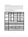
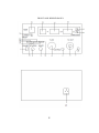
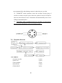
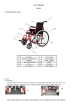
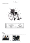
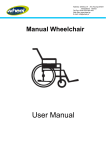
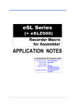
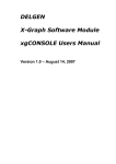
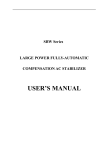
RK INSTRUMENT
ISO 9001-2000 INTERNATIONAL QUALITY
MANAGEMENT SYSTEM CERTIFICATED
RK267X
HIPOT TESTER SERIES
USER MANUAL
www.china-item.com
SHENZHEN CHUANGXIN INSTRUMENTS CO., LTD.
CONTENTS
I. General description
2
II. Main technical index
2
III. Pre-used caution
3
IV. Explain
3
V. Operation
6
VI. Principle diagram
8
VII. Instrument accessories
8
VIII. Maintenance card
9
1
I. General description.
RK267X series voltage withstand test instruments are for general- purpose HV
test operation, It can be widely used for voltage withstand test in electrician’s
assistant instrument. rubber-wooden facility. voltage convertor. wires. power
meter. motor. power supply plug. cables and all kinds of electronic and electric
products. As the launch of the national security standard, Voltage withstand
instrument has become one of necessary withstand test instruments to the radio
and electronic products manufacturer.
Operating request: environmental temperature 0~40℃
relative humidity≤75%
II. Main technic index.
MODEL
RK2670A
RK2671A
RK2672C
RK2678A
RK2674A
ITEM
RK2672A
RK2671B
RK2672B
RK2671D
RK2672D
OUTPUT VOL.
AC:0~5
INDEX
AC:0~5/10
AC:0~5;
AC:0~7.5/15
AC:0~10/20
DC:0~5
DC:0~7.5/15
DC:0~10/20
AC:0~5/10
AC:0~5
DC:0~5/10
DC:0~5
AC:0~2/20/100
AC:0~2/20
AC:0~2/20
DC:0~2/20
DC:0~2/10
DC:0~2/10
(DIGITAL DISP.)
AC:0~5
DC:0~5/10
AC:0~5
(kV)
DC:0~5
LEAK.CURR
AC:0~2/20
AC:0~2/20
(DIGITAL DISP.)
AC:0~2/20
DC:0~2/10
(mA)
DC:0~2/10
OUTPUT PWR
AC:0~2/20/50
AC:0~2/20/200
DC:0~2/10
DC:0~2/20
300VA
400VA
500VA
1000VA
AC:0~2/20/100
100VA
200VA
500VA
OUTPUT WAVE
AC 50Hz SINE WAVE
V PRECISION
±5%
A PRECISION
±5%
TIMING RANGE
1~99sec ±5% Manual test (71B for 1~999sec ±5%)
(DIGITAL DISP.)
MEAS.
320*260*180
380*280*190
WG
7Kg
15 Kg
POWER SUPPLY
DISSIPATION
AC
440*350*240
220V±10%
500*370*200
20 Kg
50Hz±2Hz
≤30W(STATIC DISSIPATION)
2
III. Pre-used caution.
Read the following items carefully before operating RK267 series voltage
withstand test instrument
(1) Use three-hole power supply plug and insure GND connection
well.
(2) GND port and power supply GND port should be connected
well
(3) Wear insulation glove, stand on
insulation mat
(4) Anti-clockwisely circumvolve “V-ADJ” rotary switch to the
maximum before turn on test instrument.
(5) Before preset all functions, reset instrument
(6) Don’t connect test port and test wire when doing test
(7) Don’t connect HV output port with shield box or GND wire to
avoid instrument damage.
(8) Turn off power when accident take place
(9) Examine and repair when Indicator or annunciator is out of
function
(10) Operate carefully to avoid hazard when take the remote test.
IV. Explain (as the front panel)
(1) Power switch: to control all power supply
(2) “START” switch: when press down the button, instrument will renew to
waiting-test status with the light working.
(3) “RESET” SWITCH: press down the button means no HV output
(4) Manual port: remote control test port
(5) “V-ADJ” rotary switch: adjust test voltage
(6)
HVOUT
2
(7)
port: test voltage output (1 port for AC test instrument and
ports for AC/DC test instrument)
GND: connect with one port of the tested
3
(8)”OVER LEAK. “indicator: “OVER LEAK.” Indication light and annunciate
work when test current leakage exceed pre-set value, voltage output will be
cut off, then press down the “REST” button and Anti-clockwisely
circumvolve “V-ADJ” rotary switch to the maximum to be ready for next test
operation.
(9) “VOLTAGE” meter: Three bits digital voltage meter, indicate output
voltage value:
(11) “ CURRENT”meter:3 1/2 digital current meter, indicate leakage current
value
(12) “TIMER”meter:2 bits digital displayer, show timing value(RK2671B 3
bits digital displayer)
(13) “TIMER” rotary switch :to adjust to set timing range
(14) “OVER LEAK.” pre-set adjustor: Press down” PRE-SET / TEST” switch
to pre-set leakage current value and display current test result
(15) “PRESET / TEST” button: Press down to preset and or else to test
(16) “CURRENT LEAK.” range: Test range are 0 ~ 2mA & 2 ~ 20mA.
(17) “CURRENT LEAK.” switch: Test range is 100mA(200mA).
(only for RK2678 )
(18) “TIMER / MANUAL” button: Press down to be timing test or else to be
manual test
(19) “AC/ DC” converting button: Press down to be DC model or else to be AC
model.
(CAUTION: only for AC/DC instrument)
(20) “Voltage output “ convert buttton: (only for RK2671&RK2678)
(21) Power plug :AC 220V plug with inner fuse
4
FRONT AND BEHIND PANEL
5
V. Operation.
(1) CONNECT POWER: Insure “V-ADJ” rotary has to be
set at “0”
position and then turn on power
(2) Set ”LEAK. CURRENT” value: Press down button”15”, adjust current
leakage preset adjustor “14” to preset needed value
(3) Connect test port: According to the request of tested object, connect test
wire with test object well.
(4) “TIMER”:Press timing button “17”to the ”TIMER” position adjust
timing rotary switch to set timing range, then press down “STARTUP”
button and adjust “V-ADJ” rotary switch to needed voltage output.
(5) “CONTRAL”:Set timing switch”18”to “manual” position, then
press
down “STARTUP” button.
(6) In test process, instrument annunciator will work to when test “over
leakage current” exceeded the pre-set over leakage current, then press
down “RESET” button to waiting test status .
(If take the manual control to test, the STARTUP button should be
unlocked)
(7) If test over leakage current is less than pre-set value, unless time is up or
press down “RESET” button ,instrument will be in the waiting test
status.
(8) Remote controller test: Insert the five-pin plug of remote controller bar
to instrument relevant plug, then press down the switch of test bar to start
to test.
Caution: Timing function is no of effect when remote control function
working at the same time.
Test example:
Condition: test voltage AC:3000V, max over leakage current AC:1.5mA,
Regular time: 30 s .
6
model:RK2671A voltage withstand test instrument.
steps:
1.Check instrument’s “V-ADJ” rotary switch to be the
anti-clockwise end position
2.Plug power wire and then turn on power button
3.Select proper range: set voltage range at”5kV”position.
4.Select proper AC&DC voltage range: set the “AC/DC” switch at “AC”
test position.
5.Select proper over leakage current range: set the over leakage current
range at “2 mA” position
6.Pre-set over leakage current value: press down” over leakage current
preset” switch to “PRESET” position, then adjust “over leakage current
preset:” switch to 1.500 mA Insure the switch to jump up and be in “TEST”
position.
7.TIMER reset: set” TIMER/ MANUAL” switch to be at ”TIMER”
position and adjust timing rotary switch at”30”seconds range.
8.Insert HV test bar to AC voltage output port, and another black pothook
connect with black GND port of instrument.
9.Connect HV test bar. GND wire and tested instrument(the style to
connect is the black clamp connecting with GND port of tested power,
HV port connecting with another port ( L or N). The tested must be put
on insulation worktable
10.Startup to test after confirming instrument setting and connection
11.Press down ”STARTUP” button, adjust “V-ADJ” rotary switch to
increase voltage until voltage meter show”3.00” kV. If tested leakage
current exceed pre-set value with voltage upgrading, annunciator will
indicate and voltage output stop, it means the tested is not passed , press
down “RESET” button to recover to origin status, or instrument will
7
reset automatically when leakage current is under the pre-set value .
12.”REMOTE” mode operation: insert the aviation five-pin plug of
test bar to remote test port, press down the switch of test bar all time to
start test, then release to reset . Instrument will automatically reset if over
leakage current take place.
13.CAUTION: Timer is disabled if test bar is working ,it is also same to
use out-control instrument’ self-service brake switch ..
VI.Principle diagram.
VII. Others.
(1)remote test bar
(2)test wire
(3)user manual
(4)certificate
(5)dust shield
1 piece
1 piece
1 piece
1 sheet
1 piece
8
VIII. Maintenance card(cut down along the dashed and post to our
corporation)
SHENZHEN CHUANGXIN INSTRUMENTS CO., LTD.
MODEL
SERIES CODE
PURCHASE DATE
USE DATE
DEPARTMENT
CONTACTOR
POST CODE
TEL.
ADDRESS
PROBLEM DESCRIPTION:
REPAIR RECORD:
SHENZHEN CHUANGXIN INSTRUMENTS CO., LTD.
ADD: No.106 Fenghe Park, Xixiang Avenue, Bao'an District, Shenzhen, Guandong, China
TEL.: +86-755-23702756-803
FAX: +86-755-61577693
http://www.china-item.com
Email: [email protected]
9