1
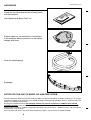
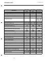
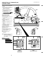
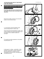
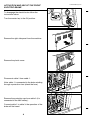
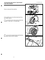
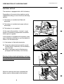
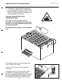
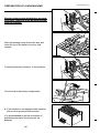
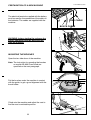
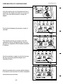
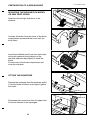
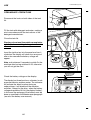
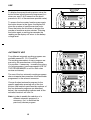
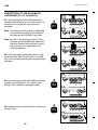
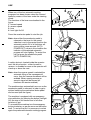
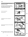
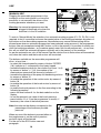
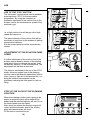
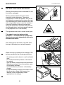
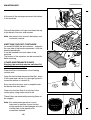
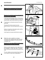
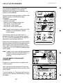
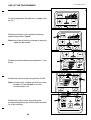
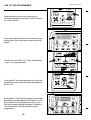
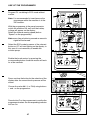
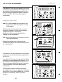
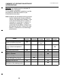
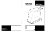
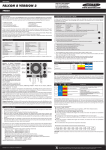
MANUAL
S31EUK4090SY(2)99-01
Operating instruction
AR 4090 EASY
AR 4100 EASY
AR 4095 FREE SCRUB
LIST OF CONTENTS
S31EUK4090SY(2)99-01
LOCALITÀ NOVELLA TERZA 26862 GUARDAMIGLIO -ITALY
MODEL
PROD. NUMBER
SERIAL NUMBER
MAX AXEL REAR
POWER
MAX AXEL FRONT
EMPTY WEIGHT
NOISE LEVEL
TOLD WEIGHT
PROTECTION
AMPERE
VOLTAGE
INTRODUCTION/GENERAL INSTRUCTIONS/SAFETY .............................................................. 1
UNPACKING .................................................................................................................................. 2
NOTES FOR THE USE OF MODEL AR 4095 FREE SCRUB ................................................. 2
TECHNICAL DATA ........................................................................................................................ 3
DESCRIPTION OF COMMANDS AND CONTROL PANEL.......................................................... 4
ACTIVATION AND USE OF THE FRONT ELECTRIC BRAKE .................................................... 5-7
PREPARATION OF A NEW MACHINE......................................................................................... 8-13
BATTERY SET UP.................................................................................................................... 8
FILLING THE BATTERY WITH SULPHURIC ACID ................................................................ 9
MOUNTING THE BRUSHES .................................................................................................... 11
MOUNTING THE BRUSHES ON MODEL AR 4095 FREE SCRUB ........................................ 13
FITTING THE SQUEEGEE ....................................................................................................... 13
USE ............................................................................................................................................... 14-20
PRELIMINARY OPERATIONS ................................................................................................. 14
AUTOMATIC USE..................................................................................................................... 15
DESCRIPTION OF THE AUTOMATIC PROGRAMS (P1, P2, P3 AND P4) ............................ 16
MANUAL USE........................................................................................................................... 19
USE OF THE “ECO” BUTTON................................................................................................. 20
ADJUSTMENT OF THE SOLUTION PUMP SPEED................................................................ 20
STOP OF THE FLOW OF THE CLEANING SOLUTION ......................................................... 20
MAINTENANCE ............................................................................................................................. 21-23
BATTERY CHECK AND RECHARGE ..................................................................................... 21
EMPTYING THE DIRT CONTAINER........................................................................................ 22
OTHER MAINTENANCE ISSUES ............................................................................................ 22
USE OF THE PROGRAMMER ...................................................................................................... 24-28
PROGRAMMING THE MACHINE: EXAMPLES ...................................................................... 24
SUMMARY OF ORDINARY MAINTENANCE INTERVENTIONS ................................................. 29
OPTIONAL ACCESSORIES .......................................................................................................... 30
SAFETY FEATURES AND TROUBLE SHOOTING...................................................................... 31
INTRODUCTION/GENERAL
INSTRUCTIONS/SAFETY
S31EUK4090SY(2)99-01
INTRODUCTION
This manual is a guide to the efficient use of the machine and also contains practical information concerning the
functioning, adjustments and user maintenance of your new scrubber/drier. Your machine has been designed and
constructed to ensure maximum performarnce and ease of operation in a wide variety of applications. Before
delivery, the machine has been tested in our factory and by our distributor to ensure that it is delivered to you in
perfect condition. To maintain the machine in this condition and guarantee functioning without problems, it is
essential that the periodic maintenance operations indicated in this manual are properly carried out. Before using the
machine, carefully read this manual and keep it within easy reach for your future reference. Indications of “LEFT” and
“RIGHT” are as seen from the operator position. If you should need any further information concerning the machine,
please do not hesitate to contact either Electrolux Euroclean or our local distributor.
GENERAL SAFETY RULES
The rules below have to be followed carefully in order to avoid damages to the operator and to the machine.
- Read the labels carefully on the machine; Do not cover them for any reason and replace them immediately if
damaged.
- Do not mix different detergents, avoiding harmful odours.
- Do not place any liquid containers onto the machine.
- The storage temperature has to be between +0°C and + 55°C.
- The perfect operating temperature should be between 0° C and 40° C.
- The humidity should be between 30 and 95%.
- Do not use the machine in explosive atmosphere.
- Do not use the machine as a means of transport.
- Do not use acid solutions which could damage the machine.
- Avoid working with the brushes when the machine stands still, in order to prevent floor damages.
- Do not vacuum iflammable liquids.
- In case of fire, use a powder extinguisher. Do not use water.
- Do not strike shelvings or scaffoldings, where there is danger of falling objects.
- Adapt the utilization speed to the adhesion conditions.
- Do not exceed over the limit gradient stated, to avoid conditions of instability (16% max).
- The machine has to carry out simultaneously the operations of washing and drying. Different operations have to be
carried out in areas which are not permitted for the passage of non employed staff. Signal the areas of moist floors
with suitable signs.
- If the machine does not work properly, check by conducting simple maintenance procedures. Otherwise, it is better
to ask for technical service.
-Where parts are required, ask for ORIGINAL spare parts to an agent and/or to an authorized dealer.
- For any maintenance operation take off the battery power supply from the machine.
- Do not take off the pieces which require the use of tools to be removed.
- Do not wash the machine with direct water jets or with high water pressure not with corrosive material.
- Every 200 working hours have a machine check through a service department.
- The machine should not be abandoned, because of the presence of toxic-harmful materials (batteries, oil etc.). This
disposal must be subject to the rules which provide for its scrapping in appropiate centres.
- The machine does not cause any harmful vibrations.
MODIFICATIONS AND IMPROVEMENTS
Electrolux Euroclean aim toward continuous improvement of its machines and reserves the right to carry out
modifications and improvements whenever necessary without being obliged to update machines which have been
sold previously.
SAFETY
You too can avoid accidents.
No accident prevention programme is effective without the total co-operation of the person directly responsible for
the functioning of the machine. The majority of accidents which may occur either during work or transferring the
machine from site to site are caused by the non-observance of the most elementary safety rules. An alert and
cautious operator is the best guarantee against accidents and is more effective than any other part of an accident
prevention programme.
The machine must be switched off and disconnected from its battery before any servicing or adjustment of
operational parts be carried out. Ensure that any assistant is clear of the machine and that covers are closed before
switching on.
During the work pay attention to the people around, especially to children.
1
UNPACKING
S31EUK4090SY(2)99-01
Check that you have received the following items
with the machine:
User Manual and Spare Parts List
Electric cables for the connection of the battery
to the machine; electric connector for the battery
charger and fuses.
Hose for tank emptying.
Squeegee.
NOTES FOR THE USE OF MODEL AR 4095 FREE SCRUB
The most important difference between model AR 4095 Free Scrub and models AR 4090 e 4100 Easy is in the type
of brushes installed on the machine. In fact model AR 4095 is equipped with cylindrical brushes, whilst the other two
models use traditional disk brushes.
By using the cylindrical brushes the sweeping function can also be carried out, in addition to the normal
scrubbing function. From the use and maintenance point of view model AR 4095 Free Scrub is identical to the
traditional Easy models; in addition the periodical emptying of the dirt container – lodged in the rear side of the brush
compartment - must be done.
It must also be said that the use of the click-Off/click-On button is not necessary for model AR 4095.
2
TECHNICAL DATA
S31EUK4090SY(2)99-01
MODELS
Working width (mm)
Squeegee width (mm)
Automatic click-on/click-off
Number of brushes and diameter (mm)
Cylindrical brushes
Brushes (RPM)
Brush motor power (W)
Brush pressure to the floor (Kg)
Solution tank capacity (lt)
Recovery tank capacity (lt)
Min/max cleaning solution flow (lt/min)
Suction motor power (W)
Suction depression (mmH2O)
Automatic solution dosing
Display for safety codes/voltmeter
Max ramp slope
Drive motor power (W)
Forward speed 1st, 2nd, 3rd (Km/h)
Reverse speed (Km/h)
Front drive wheel diameter (mm)
Rear wheels diameter (mm)
Working voltage (V)
Lenght (mm)
Width (mm)
Height (mm)
Weight (batteries not included) (Kg)
Weight (batteries included)
Suggested battery
Max working autonomy
3
AR 4090
EASY
AR 4100
EASY
AR 4095
FR. SC.
840
1130
Yes
Nr. 2 - 430
1000
1280
Yes
Nr. 2 - 500
900
1130
-
-
-
200
Nr. 2 x 500
10-80
175
180
from 1,2 to
9,5
1000
200
Nr. 2 x 500
10-90
200
205
from 1,2 to
9,5
1000
2100
Yes
Yes
16%
1200
2 - 4 - 7,2
3
300
300
36
1580
860
1290
375
760
36 V 320 Ah
4,5h
2100
Yes
Yes
16%
1200
2 - 4 - 7,2
3
300
300
36
1580
1080
1370
405
790
36 V 320 Ah
4,5h
Nr. 2
Diam. 150
Leng. 900
700
Nr. 2 x 450
10-90
200
205
from 1,5 to 9
1000
2100
Yes
Yes
16%
1200
2,5-5-7,2
3
300
300
36
1681
1053
1366
435
820
36 V 320 Ah
4,5h
DESCRIPTION OF COMMANDS AND
CONTROL PANEL
S31EUK4090SY(2)99-01
1- Button for selection of display data
2- Display
3- Indicator: solution tank empty
4- Tank emptying pump (optional): On/
Off button and indicator
5- Indicator: recovery tank full
6- Buttons and indicators for selection
of automatic working programs
7- Click-Off indicator
8- Click-Off/ Click-On button (Not used
on model AR 4095 Free Scrub)
9- Click-On indicator
10- Forward speed selection button
11- Forward speed indicators
12- Brush pressure increase
13- Brush pressure decrease
14- Electrovalves On/Off (Incr./decrease
of solution flow)
15- Solution pump: On/Off button and
indicator
16- On/Off of ECO function
17- Solution flow indicators(electrovalves
On/Off)
18- Suction motor: On/Off button and
indicator
19- Brush motors: On/Off button and
indicator
20- On/Off button and indicator of the
Programming Function
21- Removable programmer
22- Additional adjustment of solution flow
23- Emergency stop button
24- On/Off master key
25- Lever for selection of forw./rev.
speed, front light On/Off and horn
26- Rear brakes pedal
27- Forw./rev. speed accelerator
28- Steering wheel
29- Connector for removable
programmer
NOTE: The On/Off and ECO buttons (16)
enable the corresponding
function when pressed the first
time and disable it when pressed
the second time.
WARNING: The connection/
disconnection of the
removable programmer 21
in/from the connector 29
must be done with the
machine turned Off (master
key 24 in the Off position).
CONTROL PANEL FOR
MODELS
AR 4090 EASY
AR 4100 EASY
4
CONTROL PANEL FOR
MODEL
AR 4095 FREE SCRUB
ACTIVATION AND USE OF THE FRONT
ELECTRIC BRAKE
S31EUK4090SY(2)99-01
Warning: before using the machine the front
electric brake must be set according to the
folowing instructions.
Push the pedal of the rear mechanical brake
to stop the machine when removing it from
the pallet.
Remove the rubber protection from the elctric
brake on the front drive wheel.
To set the brake scews A and B must be
removed (keep them for further use)
Note: after having removed the two screws it will
not be possible to move/push the machine untill
the battery will have been installed and
activated.
Fit carefully the rubber protection on the brake.
Now the brake is set.
In the event of a failure - on the field - of the
electronic drive control in order to be able to
push the machine it is necessary first to
disengage the electric brake, according to the
following instruction.
5
A
B
ACTIVATION AND USE OF THE FRONT
ELECTRIC BRAKE
S31EUK4090SY(2)99-01
To disengage the electric brake follow the
instructions below.
Turn the master key to the Off position.
Remove the right side panel from the machine.
Remove the plastic cover.
Disconnect cable 2 from cable 1.
Note: cable 1 is connected to the brake winding
through a protection fuse (check the fuse).
1
2
Remove the protection cap from cable 3 (it is
connected to the 36V battery).
1
Connect cable 1 to cable 3: the operation of the
brake will be hared.
3
6
ACTIVATION AND USE OF THE FRONT
ELECTRIC BRAKE
Now you can push the machine.
If the machine can not yet be moved you have
two further options:
1st: to reinstall the two screws removed from the
machine - when new - to set the brake
2nd: to remove the complete brake and the brake
pad (three screws and two cables).
7
S31EUK4090SY(2)99-01
PREPARATION OF A NEW MACHINE
BATTERY SET UP
The machine is equipped with a 36 Volt battery.
Depending on the country the machine can be
supplied according to one of the three following
options:
1- The battery is installed and filled with
electrolyte
2- The battery is installed and empty (without
electrolyte)
3- The battery is not supplied.
Lift the seat of the machine - forward - to get
access to the battery compartment and check
which option is applied.
If the machine is equipped with the battery open
one of the battery cell caps to see if the battery is
filled or not with electrolyte.
1- If the battery is filled with electrolyte:
1a. Chech the electrolyte level and fill up with
distilled water if necessary (see the battery
user manual).
1b. Make a recharge (see the Maintenance
paragraph and the battery user manual).
Warning: before starting the battery recharge
the battery connector must be disconnected
from the machine.
When the recharge has been completed the
battery can be reconnected to the machine.
8
S31EUK4090SY(2)99-01
PREPARATION OF A NEW MACHINE
2- If the battery is supplied without electrolyte
(i.e. in dry charged condition) a filling must be
done with sulphuric acid (density from 1.27 to
1.29 at 25°C) according to the following rules
and to the battery user manual.
FILLING THE BATTERY WITH
SULPHURIC ACID.
Take special care: the battery acid is
corrosive; if it should come in contact with
the skin or eyes wash aboundantly with water
and consult a doctor.
The battery must be filled in a well ventilated
area.
Fill the battery cells with acid; the proper acid
level is shown in the figure.
Two hours later fill up the cells with acid if
necessary.
Let batteries rest for two further hours; then
proceed with a recharge according to the
instructions specified in the Battery User Manual
and in the MAINTENANCE paragraph. During
the recharge the battery caps must be open.
9
S31EUK4090SY(2)99-01
PREPARATION OF A NEW MACHINE
Warning: before starting the battery recharge
the battery connector must be disconnected
from the machine.
After the recharge close all the cell caps and
clean the top of the battery from any acid
remains.
Connect the battery connector to the machine.
Close the lid of the battery compartment.
3- If the machine is not equipped with batteries
they must be procured and mounted.
It is recommended to get the assistance of
qualified personnel to chose and set the
batteries.
10
S31EUK4090SY(2)99-01
PREPARATION OF A NEW MACHINE
The electrical terminals supplied with the battery
must be used for the connection of the cables to
the batteries. The cables are supplied with the
machine.
S31EUK4090SY(2)99-01
RED CABLE
BLACK CABLE
WARNING: before starting the recharge the
battery connector must be disconnected
from the machine.
MOUNTING THE BRUSHES
Open the two side doors of the machine.
Note: The instruction for mounting the brushes
on model AR 4095 Free Scrub are
specified on the next paragraph.
Put the brushes under the machine in contact
with the guide, to get a good alignment with the
brush holder.
Climb onto the machine and adjust the seat to
find the most comfortable position.
11
PREPARATION OF A NEW MACHINE
S31EUK4090SY(2)99-01
Insert the ignition key into the panel and turn it
clockwise: the display will show four zeros and
after a few seconds the battery voltage will
appear.
Push button A keeping it pressed a couple of
seconds.
A
The machine will first run trough a click-Off
sequence (indicator B lighting) and, after that,
the click-On sequence will be enabled (indicator
C lighting).
B
C
Now the machine is ready for click-On that can
be done by pressing button A again (two
seconds at least).
A
After the second action on button A the indicator
C will be On until the click-On will be completed.
Now the brushes are fitted.
C
12
PREPARATION OF A NEW MACHINE
MOUNTING THE BRUSHES ON MODEL
AR 4095 FREE SCRUB
Open the left and right side doors of the
machine.
Unscrew the knobs fixing the cover of the brush
compartment and remove the cover itself (on
both sides)
Insert the cylindrical brush (one from each side):
during this operation the guide pin on the
opposite side must be properly fit inside the
brush.
Fix the cover of the brush compartment and
close the side door.
FITTING THE SQUEEGEE
Remove the squeegee from the envelope and fit
it into the holder as shown in the figure; tighten
the knobs.
Disconnect the suction hose from its support and
fit the free terminal to the squeegee.
13
S31EUK4090SY(2)99-01
USE
S31EUK4090SY(2)99-01
PRELIMINARY OPERATIONS
Disconnect the locks on both sides of the tank
lid.
Fill the tank with detergent and water, making a
mix in accordance with the instructions of the
detergent manufacturer.
Close the tank lid.
Warning: do not use flammable nor explosive
solutions; foam making detergents are not
allowed.
Insert the ignition key into the panel and turn it
clockwise: the display will show four zeros and
after a few seconds the battery voltage will
appear.
Note: wait minimum 5 seconds to switch On the
machine after having switched it Off; otherwise
you will not get the start.
Check the battery voltage on the display.
The display has three functions: voltmeter, brush
pressure indicator and hour meter. The voltmeter
will activate the block function during an
undervoltage; it will disable all the machine
activities - except for the drive - when the battery
voltage drops below 29 Volt (the display flashes):
in this case the recharge of the battery must be
done as specified in the Maintenance paragraph
(see also the battery user manual).
14
USE
S31EUK4090SY(2)99-01
To display the current brush pressure value the
button shown in the figure must be pressed (i.e.:
when you read P 40 it means that the brush
pressure is 40% of the maximum possible value)
To access the hour meter function press again
the button shown in the figure: the display will
show the number of machine service hours.
Press the button the third time to display the
number of machine service minutes. Pressing
the button again or waiting ten seconds the
reading on the display will return to the battery
voltage level.
AUTOMATIC USE
Four different automatic working programs are
available named P1, P2, P3 and P4.
The working parameters of every program are
pre-set by the manufacturer of the machine.
It is possible - if necessary - to modify the values
of such parameters (see the paragraph USE OF
THE PROGRAMMER or ask for after sales
service assistance).
The use of the four automatic working programs
does not require the connection of the removable
programmer in the relevant connector.
Choose the best automatic program for the
specific application pressing one of the four
buttons (the functions performed by eachone of
the four automatic programs are described
below): the corresponding indicator and all the
activated functions will turn On.
Note: in order to enable the selection of a
different automatic program it is
necessary, first, to de-select the
previously chosen program.
15
USE
S31EUK4090SY(2)99-01
DESCRIPTION OF THE AUTOMATIC
PROGRAMS (P1, P2, P3 AND P4)
P1: washing program with medium intensity
(medium brush pressure, low solution flow), for
smooth floor and light dirt; drying suction
activated.
P1
Note: The content of this chapter is applicable
for all models described in this manual,
including model AR 4095 Free Scrub.
Note: the flow of the cleaning solution to the
brushes will be enabled only when both
the drive function and the brush motors
are working; this is applicable for all
working conditions.
P2: washing program with high intensity (high
brush pressure, high solution flow), for rough
floor (i.e. concrete) and heavy dirt; drying suction
activated.
P3: pre-washing program with medium intensity
(medium brush pressure, low solution flow);
drying suction disabled (squeegee lifted).
P4: drying function only (brushes not working, no
solution flow).
16
P2
P3
P4
USE
S31EUK4090SY(2)99-01
When one of the four automatic working
programs has been chosen select the forward
speed by means of the lever under the steering
wheel.
The functions of the lever are descibed in the
figure:
1- forward speed
2- reverse speed
3- horn
4- front light On/Off
Press the accelerator pedal to start the job.
Note: when either the accelerator pedal is
released or the lever for the speed
selection is set to the neutral position the
automatic switch Off of all functions will
occurr within some seconds (AUTO
POWER OFF); when in this condition the
indicator of the selected automatic
program will start lighting. To restart the
job just press the accelerator pedal
(AUTO POWER ON).
A safety device is located inside the operator
seat: the drive function - either forward or
reverse - is disabled as soon as the operator will
stand up or leave the seat.
Note: when the reverse speed is selected the
automatic lifting of the squeegee will
occur, then the reverse movement will be
enabled. When running reverse an
acoustic signal will be heared (all
functions will remain enabled).
The machine stops automatically as soon as the
accelerator pedal is released; in order to get a
quicker breaking the mechanical brake pedal
can be used (see the figure).
The machine is equipped with an emergency
stop red button; by pressing the button (red light
On) the stop of the traction and of all other
functions is got.
To re-enable the machine turn the emergency
button clockwise, as per the arrow on the button
itself. To restart the job it is necessary to select
again the preferred automatic working program.
17
4
2
1
3
USE
S31EUK4090SY(2)99-01
When the job is compleded it is necessary to
empty the recovery tank.
A level sensor is located inside the recovery
tank: when the tank is full an automatic stop of
the suction motor will occur and the
corresponding alert light will turn On.
Switch the machine Off.
Open the tank lid.
An emptying hose can be connected if
necessary.
Open the valve of the recovery tank to discharge
the dirty water.
Note: if the machine will not be used for a long
time it is better to empty the solution tank
too.
18
USE
S31EUK4090SY(2)99-01
MANUAL USE
Plugging the removable programmer in the
connector on the control panel you have the
possibility to set manually the values of the
working parameter whenever you want.
Warning: the manual programmer must be
plugged in/removed only when the
machine is in the Off condition.
To work in "Manual Mode" the selection of an automatic working program (P1, P2, P3, P4) is not
required: in fact it is possible to choose the wanted value of the working parameters by means of
the buttons on the removable programmer. Nevertheless any manual action/setting will be
allowed even when an automatic program has been selected: using anyone of the programmer
buttons (the only exceptions being the P button, nr 20 in the picture) it is possible to modify one
of/all the working parameters - e.g. machine speed, water flow, brush pressure etc. - at any time;
this will not affect the automatic programs originally set in the memory of the machine.
As per the automatic use, also in the manual use the solution flow to the brushes will be enabled
only when he traction and the brush motors will be started.
The buttons available on the removable programmer will
allow - at any time - :
- to select the forward speed by means of button "SPEED"
(10); indicator nr 1 correspond to the lowest speed
- to enable the electrovalves for the solution flow (from 1 to 4)
by means of button "+/-"(14); the number of the
electrovalves opened will be shown by indicators 17
- to enable the operation of the pump for thecleaning solution
by means of button 15
- to enable the operation of the suction motor by means of
button 18
- to enable the operation of the brush motors by means of
button 19
- to modify the brush pressure to the floor according to the
following procedure:
- press one time button A - for the data selection on the
display
- to see the presently set value of the brush pressure.
- press buttons 12 or 13 on the programmer to modify, if
necessary, the value of the brush pressure.
Note: the value on the display correspond to the
percentage of the maximum possible
pressure.
When any one of the buttons is pressed either on
the programmer or on the control panel an
acoustic signal will be heared.
For the use of the ECO button see next
paragraph.
19
A
USE
S31EUK4090SY(2)99-01
USE OF THE "ECO" BUTTON
The "economic" working mode can be enabled
pressing button "ECO" on the removable
programmer. By using this functions an
automatic adjustment of the soution flow to the
brushes versus the instantaneous speed of the
machine is got.
I.e. a high solution flow will be got with a high
speed and viceversa.
The actual intensity of the solution flow will be
monitored, in real time, by the number of lighting
electrovalve indicators.
Also the pump operation will be automatically
started.
ADJUSTMENT OF THE SOLUTION PUMP
SPEED
A further adjustment of the solution flow to the
brushes can be done by means of the rotating
knob which allows to change the speed - then
the delivery capacity - of the solution pump. This
adjustment can be done at any time.
This feature, connected to the use of the "ECO"
mode, allows an optimal use of the cleaning
solution versus the different applications (kind of
floors, heavy or light dirt to be removed etc.); so
doing the solution consumption can be
minimized, reducing the time spent for tank refilling.
STOP OF THE FLOW OF THE CLEANING
SOLUTION
When the cleaning solution tank is going to be
empty an acoustic signal will be heared (five
beeps) and the relevant indicator will turn On on
the control panel (see the figure).
After about one minute the acoustic signal will
restart and the automatic stop of the solution
pump and electrovalves will occur.
Fill the tank to continue the job.
20
MAINTENANCE
S31EUK4090SY(2)99-01
BATTERY CHECK AND RECHARGE
Warning: the machine must be switched Off and
the battery unplugged.
Make a peridical check of the level of the
electrolyte inside the battery. The battery
compartment is under the operator seat; lift the
lid of the battery compartment and open the caps
of all the battery cells: when necessary fill up the
cells using distilled water; in fact the solution of
water and sulphuric acid must be used only
during the first battery activation (filling the new
dry charged battery: see the paragraph relevant
to the preparation of a new machine).
The right electrolyte level is shown in the figure.
Take special care: the battery acid is
corrosive; if it should come in contact with
the skin or eyes wash aboundantly with water
and consult a doctor.
After refilling close the battery caps and clean
the top of the battery from any acid remains.
When necessary proceed with a recharge of the
battery according to the following instructions:
- the recharge must be done in a well ventilated
area
- turn Off the machine by means of the master
key switch
- open the battery compartment and disconnect
the battery connector from the machine; open
all the battery cell caps
- connect the battery connector to the battery
charger
- connect the battery charger to the mains: check
that the mains voltage and frequency be
identical to the corresponding values
applicable for the charger.
21
MAINTENANCE
S31EUK4090SY(2)99-01
At the end of the recharge reconnect the battery
to the machine.
Close all the battery cell caps and clean the top
of the battery from any acid remains.
Note: take always into account the battery user
instruction manual.
EMPTYING THE DIRT CONTAINER
On model AR 4095 the dirt container – lodged in
the rear side of the brush compatment - must be
emptied periodically.
It can be reached from both sides of the
machine.
The bottom of the container can be removed for
better cleaning.
OTHER MAINTENANCE ISSUES
Warning: the machine must be switched Off
and the battery unplugged.
Clean the filter in the bottom of the cleaning
solution tank.
Open the tank lid and disconnect the filter; clean
it with water and a brush (it is enough to press it
toward the bottom to reinstall it).
Every time the recovery tank is emptied clean
the basket from any debris.
Clean also the twin filter fit on the top of the
suction pipe, using water and a brush.
These filters are mounted by pressing them on
the support.
Note: this maintenace operation is most
important to maintain a good suctiondrying capability of the squeegee; also the
suction pipe could require to be
sometimes cleaned.
22
MAINTENANCE
S31EUK4090SY(2)99-01
Warning: do not put water into the suction
pipe (where the suction filter is mounted).
Warning: the machine must be switched Off
and the battery unplugged.
If the flow of the cleaning solution to the brushes
is not efficient it could be necessary to clean the
electrovalves used for the solution flow control.
To get access to the electrovalves lif the tank
backward.
Diconnect the faston contact from the
electrovalve pin; turn the electrovalve to extract
it.
Make an inspection of the electrovalve and the
relevant support and clean it.
Install again and reconnect the faston contact.
When the suction capability is reduced
disconnect the squeegee and clean the hoses
connecting the squeegee to the tank and the
squeegee itself.
Warning: for any more difficult maintenance
intervention call service assistance.
Make a periodic inspection of the rubber flaps of
the squeegee, to check their wear. The rubber
flaps can be easly replaced unscrewing the fixing
nuts.
The rear rubber can be reversed (top to bottom)
to be used two times before replacement.
23
USE OF THE PROGRAMMER
The machine is equipped with a removable
programmer allowing you to modify the
automatic working programs contained in the
memory of the machine.
Every automatic working program could include
specific values of the following working
parameters:
- machine running speed
- pressure of brushes
- intensity of the cleaning solution flow
- uso (yes/no) of the ECO mode
- uso (yes/no) of the brushes
- uso (yes/no) of the suction motor
Note: in order to get a regular solution flow to the
brushes you are obliged to use the
solution pump.
The machine operator can define up to 4
different automatic working programs (named
P1, P2, P3 and P4) depending on the different
applications and working conditions.
When the working programs have been defined
and the machine turned Off the programmer can
be removed. Then it will be possible to select
every one of the set working programs by means
of the buttons P1, P2, P3 and P4 available on the
control panel.
Note: in order to set a new working program the
machine must be in working condition (i.e.
no alert or fluid level signal must be
enabled).
PROGRAMMING THE MACHINE:
EXAMPLES
Program P1: medium intensity scrubbing with
suction enabled.
After having turned the machine Off insert the
removable programmer into the connector of the
control panel.
Turn the machine On. The display will show four
zeros for a few seconds; then the battery voltage
will appear.
24
S31EUK4090SY(2)99-01
USE OF THE PROGRAMMER
On the programmer the indicator of speed 3 will
be On.
Make the selection of the preferred working
speed using button "Speed".
Note: every time a button is pressed an acoustic
signal will be heared.
Enable two electrovalves pressing button +/- two
times.
Enable the solution pump using button On/Off.
Note: in order to get a regular solution flow to the
brushes you are obliged to use the
solution pump (On).
Enable the suction motor by pressing the
corresponding button: the suction motor will work
for a few seconds.
25
S31EUK4090SY(2)99-01
USE OF THE PROGRAMMER
Enable the brush motors by pressing the
corresponding button: the brush motors will work
for a few seconds.
Press one time the button for the selection of the
display data: the current brush pressure will be
shown.
Choose the value 50% (i.e. P 50) using buttons
+ and - on the programmer.
Press button P on the programmer to confirm the
programmed values: the corresponding indicator
will turn On.
Press button P1 on the control panel to put all the
previously programmed data into memory P1: all
the indicators on the programmer will turn Off
(the only exception being the speed 3 indicator).
Turn the machine Off before removing the
programmer.
26
S31EUK4090SY(2)99-01
USE OF THE PROGRAMMER
Program P2: scrubbing in ECO mode without
suction.
Note: it is recommended to insert/remove the
programmer while the machine is in the
Off condition.
With the programmer in the panel connector
switch the machine ON; wait until the battery
voltage will appear on the display.
Select the forward running speed (button
"Speed" on the programmer).
Note: every time a button is pressed an acoustic
signal will be heared.
Select the ECO mode by means of the relevant
button: an "E" will start lighting on the dispaly; in
this case it is not necessary to enable the
solution pump.
Enable the brush motors by pressing the
corresponding button: the brush motors will work
for a few seconds.
Press one time the button for the selection of the
display data: the current brush pressure will be
shown.
Choose the value 60% (i.e. P 60) using buttons
+ and - on the programmer.
Press button P on the programmer to confirm the
programmed values: the corresponding indicator
will turn On.
27
S31EUK4090SY(2)99-01
USE OF THE PROGRAMMER
Press button P2 on the control panel to put all the
previously programmed data into memory P2: all
the indicators on the programmer will turn Off
(the only exception being the speed 3 indicator).
Turn the machine Off before removing the
programmer.
Program P3: only suction.
Note: it is recommended to insert/remove the
programmer while the machine is in the
Off condition.
With the programmer in the panel connector
switch the machine ON; wait until the battery
voltage will appear on the display.
Select the forward running speed (button
"Speed" on the programmer).
Note: every time a button is pressed an acoustic
signal will be heared.
Enable the suction motor by pressing the
corresponding button: the suction motor will work
for a few seconds.
Press button P on the programmer to confirm the
programmed values: the corresponding indicator
will turn On.
Press button P3 on the control panel to put all the
previously programmed data into memory P3: all
the indicators on the programmer will turn Off
(the only exception being the speed 3 indicator).
Turn the machine Off before removing the
programmer.
Three different cases/examples have been
described above. For every application (different
kind of floor, of dirt to be scrubbed etc.) it will be
possible to choose the optimal automatic
program.
28
S31EUK4090SY(2)99-01
SUMMARY OF ORDINARY MAINTENACE
INTERVENTIONS
S31EUK4090SY(2)99-01
Warning: the machine must be switched Off
and the battery unplugged.
All the peridic maintenance operations must be
performed by skilled personnel or by an
authorized service centre.
Note: the battery life will depend on the good and
regular maintenance (level and density
control of the electrolyte). Besides, in the
event that the battery be not used for a
long time (i.e. more than 4 weeks) it is
necessary to recharge it, in order to
guarantee that the battery voltage never
go lower than 30 Volt. In fact a not used
battery is submitted to a self-discharge
phenomenon.
UPON
DELIVERY
CHECK
Battery voltage or every two
weeks and electrolyte level
Carbon brushes of all electric
motors (check and replace if
worn)
Rear brake adjustment
Tightening of screws and bolts
Wear of brushes
Filter cleaning
Cleaning the dirt container on
model AR 4095 Free Scrub
Gasket of the tank lid
GREAS:
the chain of the steering crown
29
WHEN
NECESSARY
EVERY 30
HOURS
EVERY 100
HOURS
EVERY 500
HOURS
●
●
OR EVERY TWO
WEEK
●
●
●
●
●
●
●
●
●
●
OPTIONAL ACCESSORIES
Flashing beacon
36V battery
Battery charger
Different kinds of brushes and pad holders
Comfort seat
Ask your nearest distributor for a complete list of
the optional accessories and advice on their use.
30
S31EUK4090SY(2)99-01
SAFETY FEATURES AND TROUBLE
SHOOTING
S31EUK4090SY(2)99-01
The machine has many safety functions.
The intervention of the safety devices is
monitored on the display of the control panel by
means of suitable safety codes; this is a help for
the identification of the malfunctions and the
possiblòe repair intervention.
The safety codes are listed in the following table.
SAFETY
CODE
TROUBLE DESCRIPTION / BEHAVIOUR
OF THE MACHINE
3_00
Traction motor overtemperature (85 °C); the machine is still
working
3_01
Safety stop of the machine due to traction motor
overtemperature (95 °C)
3_02
3_03
3_04
3_05
3_06
3_07
3_08
4_02
4_03
4_04
4_05
4_06
6_02
7_00
CHECK AND REPAIR
Check the opearation and cleaning of the front electric brake
1- check the opearation and cleaning of the front electric
brake
2- If brake is regular call for service assistance
1- check the traction motor operation, carbon brushes and its
four connection cables too
Possible failure of the electronic control of traction motor
2- if the traction motor and relevant connections are regular
ask for replacement of the power electronic board
If you are running on a ramp it could be a normal behaviour;
Traction motor overload
if the code is persistent make the same checks as per code
3_01
If the ambient temperature is higher than 35 °C or if the
Overtemperature (85 °C) of the electronic control of traction
machine is running on a ramp it could be normal; otherwise
motor: 1st alert
check the front electric brake
If the ambient temperature is higher than 35 °C or if the
Overtemperature (95 °C) of the electronic control of traction
machine is running on a ramp it could be normal; otherwise
motor: 2nd alert
check the front electric brake
1- Let the machine cool 30 minutes
Safety stop of the machine due to overtemperature (105 °C) 2- check the opearation and cleaning of the front electric
of the electronic control of traction motor
brake
3- If brake is regular call for service assistance
1- check the operation of the accelerator pedal and
microswitch
Accelerator pedal not in the neutral position at key switch On
2- check and replace - if necessary - the pedal potentiometer
or microswitch
1- check and repair cable
Broken accelerator potentiometer cable
2- if cables are regular replace the pedal potentiometer
1- check the brush motors operation, carbon brushes and
connection cables too
Possible failure of the electronic control of brush motors
2- if the brush motors are regular ask for replacement of the
power electronic board
1- reduce the brush pressure
Brush motors overload
2- if the code is persistent check the brush motors operation
or call for service assistance
Overtemperature (85 °C) of the electronic control of brush
Reduce the brush pressure
motors: 1st alert
Overtemperature (95 °C) of the electronic control of brush
Reduce the brush pressure
motors: 2nd alert
1- reduce the brush pressure and let the machine cool 30
Safety stop of the machine due to overtemperature (105 °C)
minutes
of the electronic control of brush motors
2- if the code is persistent check the brush motors operation
or call for service assistance
1- check the operation of the brush lifting system (jack motor
and two microswitches)
Failure of the brush lifting system
2- If fuses, jack motor and microswitches are regular replace
the microprocessor electronic board
24V voltage line faulty on the microprocessor electronic
board
31
1- check the fuses on the microprocessor electronic board
2- If fuses are regular replace the microprocessor electronic
board
Progetto Grafico VISUAL DIVISION Milano
S31EUK4090SY(2)99-01
Nilfisk-Advance Italia S.p.A
Località Novella Terza
26862 Guardamiglio (Lodi) Italia
Tel. +39 0377 451124
Fax +39 0377 51443