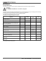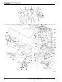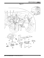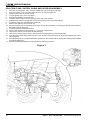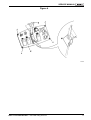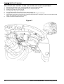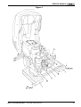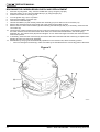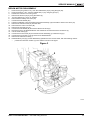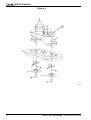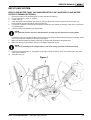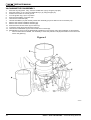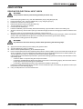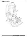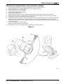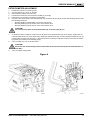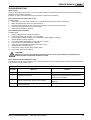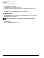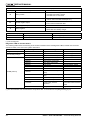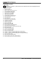
1
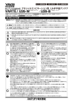
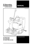
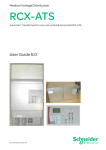
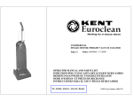
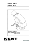
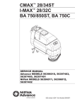
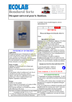
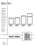
Razor™ Plus 24D-26D-28D
SERVICE MANUAL
KENT/Euroclean models:
908 7041 020 - 908 7038 020 - 908 7039 020
909 5485 000(1)2004-08
SERVICE MANUAL
GENERAL INFORMATION ...................................................................................................... 3
MACHINE LIFTING ........................................................................................................................................... 3
MACHINE TRANSPORTATION ....................................................................................................................... 3
OTHER AVAILABLE MANUALS FOR RAZOR™ PLUS 24D-26D-28D ........................................................... 3
SAFETY ............................................................................................................................................................ 4
GENERAL SAFETY RULES ............................................................................................................................. 4
TECHNICAL DATA ........................................................................................................................................... 6
MAINTENANCE ................................................................................................................................................ 8
Scheduled Maintenance .............................................................................................................................. 8
SCHEDULED MAINTENANCE CHART ........................................................................................................... 8
MACHINE NOMENCLATURE .......................................................................................................................... 9
SOLUTION SUPPLY SYSTEM .............................................................................................. 13
SOLUTION TANK AND SUPPLY SYSTEM CLEANING ................................................................................ 13
SOLUTION FILTER CLEANING ..................................................................................................................... 13
SOLUTION FLOW SYSTEM SOLENOID VALVE/FAUCET/FILTER UNIT DISASSEMBLY .......................... 14
SOLUTION FLOW CONTROL CABLE AND LEVER DISASSEMBLY ........................................................... 16
SOLUTION FLOW CONTROL CABLE AND LEVER CHECK AND ADJUSTMENT ...................................... 18
TROUBLESHOOTING .................................................................................................................................... 19
Small amount of solution or no solution flows to the broom ....................................................................... 19
The solution flows to the broom even when the machine is off ................................................................. 19
The “ECO” system does not work .............................................................................................................. 19
SWEEPING SYSTEM ............................................................................................................ 20
BROOM CLEANING ....................................................................................................................................... 20
BROOM MOTOR ELECTRICAL INPUT CHECK ........................................................................................... 20
BROOM MOTOR CARBON BRUSH CHECK AND REPLACEMENT ............................................................ 22
BROOM MOTOR DISASSEMBLY .................................................................................................................. 23
BROOM ROTATION MICROSWITCH ADJUSTMENT .................................................................................. 25
ON-BOARD ADJUSTMENT OF THE BROOM DECK LIFTING/LOWERING ACTUATOR
LIMIT SWITCH POSITIONS ........................................................................................................................... 26
Lifted deck position inspection ................................................................................................................... 26
Lowered deck position inspection .............................................................................................................. 26
Extrapressure deck position inspection ..................................................................................................... 27
Reassembly ............................................................................................................................................... 27
ADJUSTMENT OF THE BROOM DECK LIFTING/LOWERING ACTUATOR LIMIT SWITCH
POSITIONS AT THE WORKBENCH .............................................................................................................. 29
DISASSEMBLY OF THE BROOM DECK LIFTING/LOWERING ACTUATOR LIMIT MICROSWITCHES ..... 30
BROOM DECK LIFTING/LOWERING ACTUATOR DISASSEMBLY ............................................................. 31
Disassembly ............................................................................................................................................... 31
Reassembly ............................................................................................................................................... 31
TROUBLESHOOTING .................................................................................................................................... 32
Open circuit ................................................................................................................................................ 32
None of the brooms rotates ....................................................................................................................... 32
One broom does not rotate ........................................................................................................................ 32
The brooms do not reach correctly the lifted, lowered or extrapressure position
(one or more positions are wrong) ............................................................................................................. 32
Razor™ Plus 24D-26D-28D — 909 5485 000(1)2004-08
1
SERVICE MANUAL
RECYCLING SYSTEM ........................................................................................................... 33
RECYCLING WATER TANK, VACUUM GRID WITH FLOAT AND RECYCLING WATER
FILTER CLEANING (OPTIONAL) ................................................................................................................... 33
VACUUM MOTOR ELECTRICAL INPUT CHECK .......................................................................................... 34
VACUUM MOTOR CARBON BRUSH CHECK AND REPLACEMENT .......................................................... 35
VACUUM MOTOR DISASSEMBLY ................................................................................................................ 36
SQUEEGEE CLEANING/CHECK AND BLADE REPLACEMENT .................................................................. 37
Disassembly and cleaning ......................................................................................................................... 37
Check and adjustment ............................................................................................................................... 37
TROUBLESHOOTING .................................................................................................................................... 38
The vacuum motor does not turn on .......................................................................................................... 38
The vacuum motor turns on, but it turns off after a few seconds ............................................................... 38
Insufficient or no dirty water vacuum ......................................................................................................... 38
The squeegee leaves lining or it does not pick up water ........................................................................... 38
DRIVE SYSTEM ..................................................................................................................... 39
DRIVE MOTOR ELECTRICAL INPUT CHECK .............................................................................................. 39
DRIVE MOTOR CARBON BRUSH CHECK AND REPLACEMENT ............................................................... 41
DRIVE MOTOR REMOVAL ............................................................................................................................ 42
POTENTIOMETER ADJUSTMENT ................................................................................................................ 43
DRIVE MICROSWITCH ADJUSTMENT ......................................................................................................... 44
TROUBLESHOOTING .................................................................................................................................... 45
Open circuit ................................................................................................................................................ 45
Drive motor: the fuse opens the circuit ...................................................................................................... 45
The machine does not move ...................................................................................................................... 45
Drive electronic board diagnostic LED ....................................................................................................... 45
ELECTRICAL SYSTEM ......................................................................................................... 46
BATTERY REMOVAL ..................................................................................................................................... 46
BATTERY MAINTENANCE AND RECHARGING .......................................................................................... 46
DRIVE ELECTRONIC BOARD REPLACEMENT ........................................................................................... 46
FUNCTION ELECTRONIC BOARD REPLACEMENT .................................................................................... 47
FUSE CHECK/REPLACEMENT ..................................................................................................................... 48
TROUBLESHOOTING .................................................................................................................................... 48
Function board connectors ........................................................................................................................ 49
Diagnostic LED on function board ............................................................................................................. 50
COMPONENT LAYOUT ................................................................................................................................. 52
WIRING DIAGRAM ......................................................................................................................................... 56
NOTE
Forward, backward, front, rear, left or right are intended with reference to the operator’s position.
2
Razor™ Plus 24D-26D-28D — 909 5485 000(1)2004-08
SERVICE MANUAL
GENERAL INFORMATION
GENERAL INFORMATION
MACHINE LIFTING
WARNING!
Do not work under the lifted machine, if it is not securely fixed.
MACHINE TRANSPORTATION
WARNING!
Before transporting the machine, ensure that:
•
All doors and carters are closed.
•
The ignition key is not inserted.
•
The machine is firmly fastened to the means of transport.
OTHER AVAILABLE MANUALS FOR RAZOR™ PLUS 24D-26D-28D
The following manuals are available at KENT/Euroclean Literature Service Department:
–
Spare Part List of Razor™ Plus 24D-24D-28D - KENT/Euroclean 909 5429 000.
–
Instructions for Use of Razor™ Plus 24D-26D-28D - KENT/Euroclean 909 5428 000.
Razor™ Plus 24D-26D-28D — 909 5485 000(1)2004-08
3
SERVICE MANUAL
SAFETY
The following symbols indicate potentially dangerous situations. Always read this information carefully and take the
necessary precautions to protect people and objects.
DANGER!
It indicates a dangerous situation (risk of death) for the User.
WARNING!
It indicates the risk for people of being injured and for objects of being damaged.
CAUTION!
It indicates a caution or a remark related to important or useful functions. Pay particular attention to
the paragraphs marked by this symbol.
GENERAL SAFETY RULES
The following specific warnings and cautions inform you of any potential danger of damaging people or machines.
DANGER!
–
Position the machine on a level ground; before performing any maintenance/repair procedures,
turn the machine ignition key to OFF position and disconnect the battery through the special
connector.
–
This machine must be used by fully trained and authorized personnel only.
–
Keep sparks, flames and other sources of ignition away from the battery. During the normal
operation explosive gases are released.
–
Do not wear jewels when working near electrical components.
–
Do not work under the lifted machine, if it is not securely fixed.
–
Do not operate the machine near toxic, dangerous, inflammable and/or explosive powders,
liquids or vapors.
–
Battery charging produces highly explosive hydrogen gas. Keep the tank assembly open during
battery charging and perform this procedure only in well-ventilated areas and away from naked
flames.
4
Razor™ Plus 24D-26D-28D — 909 5485 000(1)2004-08
SERVICE MANUAL
WARNING!
–
Carefully read all maintenance/repair instructions before performing any maintenance/repair
procedure.
–
Before using the battery charger, ensure that frequency and voltage values, indicated in the
machine serial number plate, match the mains voltage.
–
Take all necessary precautions to prevent hair, jewels and loose clothes from being caught by the
machine moving and vacuuming parts.
–
Do not smoke during battery charging.
–
Before leaving the machine unattended, make sure that the machine cannot move and remove the
ignition key.
–
Do not use the machine on surfaces with a gradient greater than the one indicated on the
machine.
–
Do not wash the machine with direct or pressurized water jets, or with corrosive substances.
–
Do not use the machine in particularly dusty areas.
–
While using this machine, take care not to cause damage to other people.
–
The storage temperature must be between +32°F and +104°F (0°C and +40°C).
–
The machine operating temperature must be between +32°F and 104°F (0°C and +40°C).
–
Humidity must be between 30% and 95%.
–
Always protect the machine from the sun, rain and bad weather, when it is both in the operating
and stationary state.
–
Do not use the machine as a means of transport.
–
Do not use the machine on ramps or slopes with an inclination higher than 2%.
–
Do not allow the broom to operate while the machine is stationary to avoid damaging the floor.
–
In case of fire, possibly use a powder fire extinguisher, not a water fire extinguisher.
–
Do not bump into shelves or scaffoldings, particularly where there is a risk of falling objects.
–
Do not remove or modify the plates affixed to the machine.
–
If parts must be replaced, contact an Authorized Dealer or Retailer for ORIGINAL spare parts.
–
The machine must be disposed of properly, because of the presence of toxic-harmful materials
(batteries, etc.), which are subject to standards that require disposal in special centers (see
chapter “Scrapping”).
–
Do not let any object enter the openings. Do not use the machine in case the openings are
clogged; always keep the openings free from dust, hairs and any other foreign material which
could reduce the air flow.
–
This machine cannot be used on public roads or streets.
–
Pay attention during the machine transfers when temperature is below the freezing point. The
water in the recycling tank or in the pipes could freeze and seriously damage the machine.
–
Only use the brooms and pads/cylindrical brooms supplied with the machine and those specified
in the Instructions for Use Manuals. Using other brooms or pads/cylindrical brooms could reduce
safety.
Razor™ Plus 24D-26D-28D — 909 5485 000(1)2004-08
5
SERVICE MANUAL
TECHNICAL DATA
Dimensions
Scrubbing width
Squeegee width
26D
28D
24.0 in (610 mm)
26.0 in (660 mm)
29.0 in (740 mm)
32.0 in (812 mm)
34.0 in (860 mm)
Machine length (max)
59 in (1,500 mm)
Machine height
42 in (1,065 mm)
Machine width without squeegee
26.0 in (658 mm)
26.8 in (681.5 mm)
30.0 in (758 mm)
Broom diameter
12.0 in (305 mm)
13.0 in (330 mm)
14.5 in (370 mm)
Fresh water tank capacity
21 gal (80 liters)
Dirty water tank capacity
21 gal (80 liters)
Weight without batteries and with empty tanks
264 lb (120 kg)
Front wheels on fixed axle
Front wheels, specific ground pressure
Rear pivoting wheel
Ø 10.5 in (267 mm)
Less than 0.5 N/mm2
Ø 3.9 in (100 mm)
Vacuum motor power
0.68 HP (500 W)
Rated power broom motor
0.54 HP (400 W)
Broom speed
Broom ground pressure
Drive motor power
Drive speed (variable)
Maximum gradient
Sound pressure level (at the Operator's
position)
Standard batteries (with case)
Battery compartment dimensions (with case)
Vacuum circuit
6
24D
0 to 220 rpm
66 to 110 lb (30 to 50 kg) with gas spring
0.27 HP (200 W)
0 to 3.2 mph (0 to 5.2 km/h)
2%
65 dBA
24V 195Ah (WET)/24V 238Ah (WET)
20.8 x 15.0 in, height 14.7 in (530 x 380 mm, height 375 mm)
59.8 in H2O (1,520 mm H2O)
Razor™ Plus 24D-26D-28D — 909 5485 000(1)2004-08
SERVICE MANUAL
Razorô Plus 24D
Razorô Plus 26D
1470
835
592
669
835
645
592
1067
1067
1473
Razorô Plus 28D
893
592
748
1067
1489
S300617
Razor™ Plus 24D-26D-28D — 909 5485 000(1)2004-08
7
SERVICE MANUAL
MAINTENANCE
Scheduled Maintenance
The lifespan of the machine and its maximum operating safety are ensured by regular maintenance.
WARNING!
See “GENERAL INFORMATION” and “SAFETY” paragraphs.
The following chart provides the Scheduled Maintenance. The intervals shown may vary according to particular working
conditions, which are to be defined by the person in charge of the maintenance.
For maintenance operation instructions, see the following paragraphs.
SCHEDULED MAINTENANCE CHART
Operation
Daily, after
machine use
Weekly
Every six
months
Yearly
Squeegee cleaning
Squeegee blade check (and replacement)
Broom/pad/cylindrical broom cleaning
Tank, vacuum grid with float and recycling water
filter cleaning (optional)
Solution filter cleaning
Battery charging
Lead (WET) battery liquid level check
Broom-holder deck lifting/lowering actuator
adjustment check
(1)
Vacuum motor seal efficiency check
Screw and nut tightening check
(1)
Broom/pad/cylindrical broom electric motor carbon
brush check or replacement
Vacuum electric motor carbon brush check or
replacement
Drive electric motor carbon brush check or
replacement
(1): and after the first 8 working hours
8
Razor™ Plus 24D-26D-28D — 909 5485 000(1)2004-08
SERVICE MANUAL
MACHINE NOMENCLATURE
Throughout this Manual you will find numbers in brackets – for example: (2). These numbers refer to the components
indicated in these two nomenclature pages. Refer to these pages whenever it will be necessary to identify a component
mentioned in the text.
1.
2.
3.
4.
5.
6.
7.
8.
9.
9a.
9b.
9c.
10.
11.
12.
13.
14.
15.
16.
17.
18.
19.
20.
21.
22.
23.
24.
25.
26.
27.
28.
29.
30.
31.
32.
33.
34.
35.
36.
37.
38.
39.
40.
41.
42.
43.
44.
45.
46.
Control panel and commands
Broom/pad/cylindrical broom-holder deck
lifting/lowering switch
Broom/pad extrapressure switch
Solution flow control lever
ECO position of the solution flow control lever (water
“economy” usage, for a washing autonomy of about 66
minutes)
Broom/pad control switch
Machine forward/reverse speed adjuster
Hour counter
Battery charge status indicator
Green warning light (when ON: charged batteries)
Yellow warning light (when ON: nearly discharged
batteries)
Red warning light (when ON: discharged batteries)
Ignition key (0 - I)
Serial number plate / technical data
Machine handlebar
Handlebar inclination adjusting handles
Machine forward/reverse and broom/pad/cylindrical
broom rotation paddle
Glove compartment
Pocket
Tank cover
Rear pivoting wheel
Front wheels on fixed axle
Wheel cover
Broom or pad-holder with pad
Broom/pad-holder deck
Front spoiler
Cylindrical broom
Roller-holder deck
Squeegee
Squeegee fixing handwheels
Squeegee balance adjusting handwheel
Front squeegee blade
Rear squeegee blade
Rear blade fixing hook
Front squeegee blade fixing wing nuts
Rear squeegee blade fixing wing nuts
Squeegee vacuum pipe
Squeegee lifting lever
Recycling water drain pipe
Solution drain pipe
Solution filter
Solution faucet
Battery (red) connector
This connector also serves as EMERGENCY switch to
immediately stop all functions.
Battery charger cable
Battery charger cable holder
Battery charger data inspection window
Parking brake (optional)
Recycling water switch (optional)
Drive on/off switch
(for pushing/towing the machine)
Razor™ Plus 24D-26D-28D — 909 5485 000(1)2004-08
47.
48.
49.
50.
51.
52.
53.
54.
55.
56.
57.
58.
59.
60.
61.
62.
63.
64.
65.
66.
67.
68.
69.
70.
71.
72.
73.
74.
75.
76.
77.
78.
79.
80.
81.
82.
83.
84.
85.
86.
87.
88.
89.
90.
91.
92.
93.
94.
95.
96.
97.
Electronic battery charger
Red warning light (when ON: battery charging)
Yellow warning light (when ON: battery charging almost
completed)
Green warning light (when ON: charged battery)
Lead (WET) or gel (GEL) battery selector switch,
positioned on the electronic battery charger
Lead (WET) or gel (GEL) battery selector switch,
located on the Function electronic board
Drive electronic board
Function electronic board
Drive electronic board protection fuse
Function electronic board protection fuse
Electrical component cover
Cover gasket
Rubber protection panel
Battery connector
Battery charger cable
Battery charger cable holder
Squeegee lifting lever handle
Cover fixing nuts
Vacuum automatic cut-off switch
Tank assembly release handwheel
Tank cover (open position)
Tank cover gasket
Compensation hole
Recycling water tank
Solution tank
Vacuum grid with float-type automatic shut-off
Vacuum motor
Broom/pad/cylindrical broom motors
Batteries
Battery caps
Possible battery assembly diagrams
Tank assembly (in lifted position)
Broom/pad-holder deck
Roller-holder deck
Broom/pad deck fixing handwheel
Broom/pad deck retaining split pins
Broom/disk motor connector
Broom
Pad-holder
Pad
Cylindrical brooms
Solution feed (removable) pipe
Battery case
Splash-guard
Vacuum motor seals
Recycling water filter (optional)
Solution tank marks
Solution drain pipe
Broom-holder deck lifting/lowering actuator
Vacuum pipe trap rubber
Recycling water floating switch (optional)
9
SERVICE MANUAL
S300618
10
Razor™ Plus 24D-26D-28D — 909 5485 000(1)2004-08
SERVICE MANUAL
S300619
Razor™ Plus 24D-26D-28D — 909 5485 000(1)2004-08
11
SERVICE MANUAL
S300620
12
Razor™ Plus 24D-26D-28D — 909 5485 000(1)2004-08
SERVICE MANUAL
SOLUTION SUPPLY SYSTEM
SOLUTION SUPPLY SYSTEM
SOLUTION TANK AND SUPPLY SYSTEM CLEANING
1.
2.
3.
4.
5.
6.
7.
Place the machine in the area designed for the solution and recycling water disposal.
Empty the solution tank (71) through the pipe (94).
Turn the solution flow control lever (4) to the wide-open position, then operate the machine until the solution inside
the machine runs out.
Turn the ignition key (10) to “0” position.
Wash the tank (71) by using fresh water.
Operate the machine until the solution inside the machine runs out.
Carry out the solution filter cleaning (see the following procedure).
SOLUTION FILTER CLEANING
1.
2.
3.
4.
Position the machine on a level ground.
Turn the ignition key (10) to “0” position.
Close the solution faucet (A) from the right lower side of the machine. The faucet (A) is closed when it is in position
(B) as to the pipeline; it is open when it is in position (C).
Remove the transparent cover (D) and the strainer (E) from the left lower side of the machine (at the “FILTER”
mark); then clean and reinstall them on the holder (F).
NOTE
Correctly position the strainer (E) in the holder (F) housing (G).
5.
Re-open the faucet (A).
Figure 1
S300621
Razor™ Plus 24D-26D-28D — 909 5485 000(1)2004-08
13
SERVICE MANUAL
SOLUTION FLOW SYSTEM SOLENOID VALVE/FAUCET/FILTER UNIT DISASSEMBLY
1.
2.
3.
4.
5.
6.
7.
8.
Drain the recycling water, if any, from the related tank (70) by using the pipe (36).
Drain the solution, if any, from the related tank (71) by using the pipe (37).
Position the machine on a level ground.
Turn the ignition key (10) to “0” position.
Disconnect the battery connector (40).
Close the solution faucet (A) from the right lower side of the machine.
Slightly lift the machine left side and remove the hoses (B) and (C) from their fittings.
Mark the position of the clamp (D) on the faucet control cable sheath (E); loosen the clamp (D) and release the
sheath (E).
Remove the cable (F) from the lever (G).
NOTE
When reassembling, tighten the sheath (E) through the clamp (D) into its position, by using the
reference marks made before disassembly, not to change the adjustment of the faucet control.
9.
10.
11.
12.
13.
14.
15.
Unscrew the screw (P) and disconnect the solenoid valve (Q).
Unscrew the fixing screws (H) of the solenoid valve-faucet-filter assembly holder.
Remove the solenoid valve-faucet-filter assembly (I).
Place the assembly on the workbench, and unscrew the fittings (N) / screws (O) to remove the solenoid valve (J) /
the faucet (K) / the filter unit (L).
If necessary, remove dirt or limestone from the solenoid valve (J) inner seal, after disassembling it according to the
following procedure:
–
Loosen the retainer ring (S), then remove the coil.
–
Unscrew the four solenoid valve fixing screws (T) and its seal.
–
After cleaning the inner seal, reassemble the solenoid valve by carrying out the disassembly operations in the
reverse order. Make sure that you correctly replace the seal into its seat.
If necessary, remove dirt or limestone from the faucet (K); in particular, clean the solution “ECO” flow inner hole (R).
Reassemble by carrying out the disassembly operations in the reverse order.
NOTE
When reassembling the solenoid valve (D), the orientation of the arrow (M) must be as shown in the
figure (in the direction of the solution flow); furthermore, before installing the previously removed
fittings (N), clean the related threads and apply LOCTITE 572 sealant.
14
Razor™ Plus 24D-26D-28D — 909 5485 000(1)2004-08
SERVICE MANUAL
Figure 2
S300622
Razor™ Plus 24D-26D-28D — 909 5485 000(1)2004-08
15
SERVICE MANUAL
SOLUTION FLOW CONTROL CABLE AND LEVER DISASSEMBLY
1.
2.
3.
4.
5.
6.
7.
8.
9.
10.
Drain the recycling water, if any, from the related tank (70) by using the pipe (36).
Drain the solution, if any, from the related tank (71) by using the pipe (37).
Position the machine on a level ground.
Turn the ignition key (10) to “0” position.
Disconnect the battery connector (40).
Close the solution faucet (A) from the right lower side of the machine.
Slightly lift the machine left side and remove the hoses (B) and (C) from their fittings.
Loosen the clamp (D) and release the sheath (E).
Remove the cable (F) from the lever (G).
Connect a probe (cord or equivalent) to the cable end (F) (this operation is necessary to facilitate the insertion of
the cable inside the machine).
11. Lower the machine left side to the floor.
12. Remove the handle (H) from the lever (I), by using the control panel.
13. Unscrew the screws (J) and slightly lift the panel (K).
14. Unscrew the screws with the nut (L) and remove the lever assembly (I) from the panel (K).
15. Take the control cable (M) and the lever out of the machine, leaving the probe in its place (to facilitate the control
cable insertion).
16. Reassemble by carrying out the disassembly operations in the reverse order, by placing the clamp (D) on the sheath
(E) without tightening it.
17. Perform the Cable Adjustment, as described in the following procedure.
Figure 3
S300623
16
Razor™ Plus 24D-26D-28D — 909 5485 000(1)2004-08
SERVICE MANUAL
Figure 4
S300624
Razor™ Plus 24D-26D-28D — 909 5485 000(1)2004-08
17
SERVICE MANUAL
SOLUTION FLOW CONTROL CABLE AND LEVER CHECK AND ADJUSTMENT
1.
2.
3.
4.
5.
6.
7.
8.
Drain the recycling water, if any, from the related tank (70) by using the pipe (36).
Drain the solution, if any, from the related tank (71) by using the pipe (37).
Position the machine on a level ground.
Turn the ignition key (10) to “0” position.
Turn the solution flow control lever (4) to the “ECO” position (5).
Slightly lift the machine left side and loosen the clamp (A) by releasing the sheath (B).
Check that the faucet flow control lever (C) is at the left end (as shown in the figure), if not, turn it to the left end and
tighten the sheath (B) by using the clamp (A).
Lower the machine left side to the floor.
Figure 5
18
Razor™ Plus 24D-26D-28D — 909 5485 000(1)2004-08
SERVICE MANUAL
TROUBLESHOOTING
Small amount of solution or no solution flows to the broom
Possible cause:
1.
The broom switch (2) is not in the ON position or it is faulty (turn ON or repair/replace).
2.
The solution filter is clogged/dirty (clean).
3.
The solution flow control lever does not control the related faucet (check the operation of the control cable from the
lever to its faucet).
4.
The solution supply faucet is stuck closed (replace).
5.
The solenoid valve is faulty or there is an open circuit in the connection (replace the solenoid valve/restore the
connection).
6.
There is debris in the solution tank obstructing the output hole (clean the tank).
7.
There is debris in the pipe obstructing the solution passage (clean the pipe).
The solution flows to the broom even when the machine is off
Possible cause:
1.
There is dirt or limestone on the solenoid valve seals (clean the solenoid valve inner seals)
2.
The solenoid valve is faulty (replace).
The “ECO” system does not work
Possible cause:
1.
There is dirt in the ball inside the faucet (remove any deposit)
Razor™ Plus 24D-26D-28D — 909 5485 000(1)2004-08
19
SERVICE MANUAL
SWEEPING SYSTEM
SWEEPING SYSTEM
BROOM CLEANING
CAUTION!
It is advisable to use protective gloves when cleaning the brooms/pads/cylindrical brooms as there
may be cutting debris.
1.
2.
3.
Remove the brooms (84) by using the switch (6).
Clean and wash the brooms with water and solution.
Check that the broom bristles are integral and not excessively worn; otherwise replace the brooms.
The brooms are to be considered worn when their bristles reach a length of 20 mm (that is, half their original length).
BROOM MOTOR ELECTRICAL INPUT CHECK
WARNING!
This procedure must be performed by qualified personnel only.
1.
Drain the recycling water, if any, from the related tank (70) by using the pipe (36).
2.
Drain the solution, if any, from the related tank (71) by using the pipe (37).
3.
Position the machine on a level ground.
4.
Remove the brooms (84) by using the switch (6).
5.
Turn the ignition key (10) to “0” position.
6.
Turn the drive on/off switch (46) to “0” position.
7.
Unscrew the handwheel (66).
8.
Hold the handlebar (12) and carefully lift the tank assembly (78) to be able to work on the deck (79).
9.
Apply ammetric pliers (D) on the motor (F) electrical cable (E) or on the motor (H) electrical cable (G).
10. Turn the ignition key (10) to “I” position.
11. Remove the brooms (84) or the pad-holders (85) by using the switch (6).
12. Place two wooden shims (I) under the deck sides (L), as shown in the figure.
The wooden shim thickness must be about 140 mm
WARNING!
Keep the wooden shims (I) at a proper distance from the hubs (M).
13.
14.
15.
Lower the deck (L) on the wooden shims (I) by using the switch (2). Check the hubs (M) do not touch the floor.
Push the forward/reverse and broom/pad/cylindrical broom rotation paddle (14) and check that the electrical input
of the motor (F) or (H) at 24 V is between 3 and 5A. Release the forward/reverse and broom/pad/cylindrical broom
rotation paddle (14). Turn the ignition key (10) to “0” position and remove the ammetric pliers (D).
If the electrical input exceeds the specifications, perform the following operations to identify and eliminate the cause
of the faulty input:
–
Check the broom/pad-holder hub (M) for debris or dirt (cords, cables, etc.).
–
Check the motor carbon brushes (see the procedure on the following page).
–
If necessary, disassemble the motor (see the procedure on the following pages) and check all its parts.
If the above-mentioned procedures do not lead to a correct electrical input, it is necessary to replace the motor (see
the procedure on the following pages).
Carry out steps from 4 to 13 in the reverse order.
20
Razor™ Plus 24D-26D-28D — 909 5485 000(1)2004-08
SERVICE MANUAL
Figure 1
40
S300626
Razor™ Plus 24D-26D-28D — 909 5485 000(1)2004-08
21
SERVICE MANUAL
BROOM MOTOR CARBON BRUSH CHECK AND REPLACEMENT
1.
2.
3.
4.
5.
6.
7.
8.
9.
10.
11.
12.
Drain the recycling water, if any, from the related tank (70) by using the pipe (36).
Drain the solution, if any, from the related tank (71) by using the pipe (37).
Position the machine on a level ground.
Turn the ignition key (10) to “0” position.
Disconnect the battery connector (40).
Unscrew the handwheel (66).
Hold the handlebar (12) and carefully lift the tank assembly (78) to be able to work on the deck (79).
Remove dirt and dust from the motor outer part in the carbon brush holder (A) area.
Remove the four carbon brush holders (A) after releasing the retainers (B) and (C). If necessary, disconnect the
connectors (D).
Check the four carbon brushes (E) for wear; the carbon brushes are worn when there is not sufficient contact with
the motor armature, because of the carbon brush wear, the contact surface deterioration, the thrust spring
breakage, etc. The carbon brush (E) minimum length is 15 mm: when this length is reached, the carbon brushes
have to be replaced.
If necessary, disconnect the connectors (F) and remove the carbon brushes with their holders (A) to replace them.
Replace all carbon brushes as an assembly.
Reassemble by carrying out the disassembly operations in the reverse order, with the following caution:
–
when connecting the terminals (F), make sure that they are insulated from the surrounding parts of the frame.
Figure 2
S300627
22
Razor™ Plus 24D-26D-28D — 909 5485 000(1)2004-08
SERVICE MANUAL
BROOM MOTOR DISASSEMBLY
1.
Drain the recycling water, if any, from the related tank (70) by using the pipe (36).
2.
Drain the solution, if any, from the related tank (71) by using the pipe (37).
3.
Position the machine on a level ground.
4.
Remove the brooms (84) by using the switch (6).
5.
Turn the ignition key (10) to “0” position.
6.
Disconnect the battery connector (40).
7.
Unscrew the handwheel (66).
8.
Hold the handlebar (12) and carefully lift the tank assembly (78) to be able to work on the deck (79).
9.
Remove the solution hoses (A) from the deck.
10. Disconnect the motor connector (B).
11. Remove the two split pins (C).
12. Unscrew the handwheel (D) and remove the broom deck (E).
13. Place the motor to be disassembled on the workbench and disconnect the connectors (F).
14. Cut the motor clamp (G).
15. Unscrew the motor screw (H) and remove the hub assembly (I); extract the key (K).
16. Unscrew the four screws (J) of the motor to be disassembled.
17. Remove the reduction motor (L).
18. Reassemble by carrying out the disassembly operations in the reverse order, with the following caution:
–
position the reduction motors (L) in the direction shown in the figure.
Figure 3
S300628
Razor™ Plus 24D-26D-28D — 909 5485 000(1)2004-08
23
SERVICE MANUAL
Figure 4
S300629
24
Razor™ Plus 24D-26D-28D — 909 5485 000(1)2004-08
SERVICE MANUAL
BROOM ROTATION MICROSWITCH ADJUSTMENT
1.
2.
3.
4.
5.
6.
Position the machine on a level ground.
Turn the ignition key (10) to “0” position.
Disconnect the battery connector (40).
Unscrew the screws (A) and remove the paddle (C) cover (B).
With the paddle (C) released, check that the microswitch (E) actuator (D) is in the cam (I) housing (F); also check
that the contacts connected to the cables (N) are open (use a tester).
Push the paddle (C) and check that the actuator (D) in positions (G) and (H) activates the microswitch (E) (a “click”
must be heard); also check that the contacts connected to the cables (N) are closed (use a tester).
If necessary, reach the required condition by loosening the screws (L) and adjusting the cam (I) position and/or
loosening the screws (M) and adjusting the microswitch (E) position. Tighten the screws.
CAUTION!
When reconnecting the microswitch connectors (N), make sure you reposition them on the same
contacts (contact “C” and contact “NO”).
7.
8.
Reassemble by carrying out the disassembly operations in the reverse order.
Carry out some tests to check the broom rotation.
Figure 5
S300630
S300631
Razor™ Plus 24D-26D-28D — 909 5485 000(1)2004-08
25
SERVICE MANUAL
ON-BOARD ADJUSTMENT OF THE BROOM DECK LIFTING/LOWERING ACTUATOR
LIMIT SWITCH POSITIONS
1.
2.
3.
4.
Drain the recycling water, if any, from the related tank (70) by using the pipe (36).
Drain the solution, if any, from the related tank (71) by using the pipe (37).
Position the machine on a level ground.
Make sure that the brooms (I) are installed on the machine.
NOTE
To perform this adjustment, new brooms (not worn ones) should be used. See the note at step 12
below.
5.
6.
7.
Turn the ignition key (10) to “0” position.
Unscrew the handwheel (66).
Hold the handlebar (12) and carefully lift the tank assembly (78) to be able to work on the deck (79).
Lifted deck position inspection
8.
Turn the ignition key (10) to “I” position and lift the broom deck (22) by using the switch (2). Turn the ignition key
(10) to “0” position.
9.
When the broom deck (A) is in the lifted position, check that the deck contacts the rubber pad (B) and the deck
upper side (C) is horizontally positioned. If necessary, restore this condition by proceeding as follows.
10. Unscrew the screws (D) and remove the cover (E) with the gasket (F).
Loosen the cam dowel (G) and rotate the cam by varying the microswitch (H) actuation point as necessary; tighten
the cam dowel.
NOTE
When advancing or retarding the cams, remember that they rotate clockwise during the actuator
descent.
Turn the ignition key (10) to “I” position and lower and lift the broom deck (A) by using the switch (2), then turn the
ignition key (10) to “0” position and repeat the inspection described at step 8.
Lowered deck position inspection
11. Turn the ignition key (10) to “I” position and lower the broom deck (22) by using the switch (2). Turn the ignition key
(10) to “0” position.
12. When the broom deck is in the lowered position (A), check that the screw (L) is approximately in position (M) on the
slot (N). If necessary, restore this condition by proceeding as follows.
NOTE
Position (M) refers to the deck positioning when new brooms are installed. The slot (N) upper space
reduces by the same amount as the broom wear.
13.
Unscrew the screws (D) and remove the cover (E) with the gasket (F), if you haven't done it yet.
Loosen the cam dowel (O) and rotate the cam by varying the microswitch (P) actuation point as necessary; tighten
the cam dowel.
Turn the ignition key (10) to “I” position and lift and lower the broom deck (A) by using the switch (2), then turn the
ignition key (10) to “0” position and repeat the inspection described at step 12.
26
Razor™ Plus 24D-26D-28D — 909 5485 000(1)2004-08
SERVICE MANUAL
Extrapressure deck position inspection
14. Turn the ignition key (10) to “I” position and lower the broom deck (22) in the extrapressure position by using the
switch (3). Turn the ignition key (10) to “0” position.
15. When the broom deck (A) is lowered in the extrapressure position, check that the lever (J) is at about 20-25 mm
from the stop (K), as shown in the figure. If necessary, restore this condition by proceeding as follows.
16. Unscrew the screws (D) and remove the cover (E) with the gasket (F), if you haven't done it yet.
Loosen the cam dowel (Q) and rotate the cam by varying the microswitch (R) actuation point as necessary; tighten
the cam dowel.
Turn the ignition key (10) to “I” position and lift and lower the broom deck (A) in the extrapressure position by using
the switch (3), then turn the ignition key (10) to “0” position and repeat the inspection described at step 15.
NOTE
If necessary, the actuator limit switch positions can also be adjusted at the workbench; see the
procedure in the relevant paragraph.
Reassembly
17. Position the cover (E) with the gasket (F) into its seat, then tighten the screws (D).
18. Carry out steps from 1 to 7 in the reverse order.
Razor™ Plus 24D-26D-28D — 909 5485 000(1)2004-08
27
SERVICE MANUAL
Figure 6
S300632
28
Razor™ Plus 24D-26D-28D — 909 5485 000(1)2004-08
SERVICE MANUAL
ADJUSTMENT OF THE BROOM DECK LIFTING/LOWERING ACTUATOR LIMIT SWITCH
POSITIONS AT THE WORKBENCH
NOTE
The spare actuator has already been adjusted by the Manufacturer.
When performing the following adjustment at the workbench, it is not necessary to adjust the actuator
after installing it on the machine.
1.
2.
Unscrew the screws (A) and remove the cover (B) with the gasket.
Check the actuator (L) dimensions (C) in the different conditions described in the following adjustment chart.
To activate the actuator at the workbench, supply it with 24V voltage on the red and blue cables.
To adjust the various positions of the limit switches, loosen the dowel of the related cam (D, E, F) and rotate the
cam by varying the related microswitch (G, H, I) actuation point as necessary; then tighten the cam dowel.
NOTE
When advancing or retarding the cams, remember that they rotate clockwise during the actuator
extension.
NOTE
After adjusting, stop the actuator in the working position, to facilitate the reassembly procedure.
Figure 7
MICROSWITCH (G, H, I) ADJUSTMENT
Microswitch
activated
Dimension (C)
Related actuator
position
G
268 ± 2
lifted
H
342 ± 2
working
I
385 ± 2
extrapressure
S300652
Razor™ Plus 24D-26D-28D — 909 5485 000(1)2004-08
29
SERVICE MANUAL
DISASSEMBLY OF THE BROOM DECK LIFTING/LOWERING ACTUATOR LIMIT
MICROSWITCHES
1.
2.
3.
4.
Drain the recycling water, if any, from the related tank (70) by using the pipe (36).
Drain the solution, if any, from the related tank (71) by using the pipe (37).
Position the machine on a level ground.
Make sure that the brooms (I) are installed on the machine.
NOTE
To perform the actuator adjustment described at step 11 below, new brooms (not worn ones) should
be used.
5.
6.
7.
8.
9.
10.
Turn the ignition key (10) to “0” position.
Unscrew the handwheel (66).
Hold the handlebar (12) and carefully lift the tank assembly (78) to be able to work on the deck (79).
Unscrew the screws (A) and remove the cover (B) with the gasket (C).
Unscrew the microswitch fixing screws (D).
Disconnect the connectors of the microswitches (E), (F) or (G) to be replaced, then remove the microswitches.
When reassembling, make sure you don't invert the connectors of the microswitches (E, F, G); see the chart below
providing the correct microswitch connectors.
11. Perform the Adjustment of the Broom Deck Lifting/Lowering Actuator Positions, as described in the previous pages.
NOTE
If necessary, the actuator limit switch positions can also be adjusted at the workbench; see the
procedure in the relevant paragraph.
Figure 8
MICROSWITCH CONNECTION CHART
Microswitch
Wiring
diagram
reference
Cable
(machine
wiring
harness)
Adjusted
position
E
SW8
orange
extrapressure
F
SW7
yellow
working
G
SW6
white
lifted
S300633
30
Razor™ Plus 24D-26D-28D — 909 5485 000(1)2004-08
SERVICE MANUAL
BROOM DECK LIFTING/LOWERING ACTUATOR DISASSEMBLY
Disassembly
1.
Drain the recycling water, if any, from the related tank (70) by using the pipe (36).
2.
Drain the solution, if any, from the related tank (71) by using the pipe (37).
3.
Position the machine on a level ground.
4.
Make sure that the brooms (I) are installed on the machine.
NOTE
To perform the actuator adjustment described at step 11 below, new brooms (not worn ones) should
be used.
5.
6.
7.
8.
9.
Turn the ignition key (10) to “0” position.
Unscrew the handwheel (66).
Hold the handlebar (12) and carefully lift the tank assembly (78) to be able to work on the deck (79).
Disconnect the actuator electrical connector (A).
Unscrew the bolts (B) and (C), then remove the actuator (D).
Reassembly
10. Position the actuator (D) into its seat, then screw the bolts (B) and (C); do not tighten the nuts, but leave the
necessary play for the articulation to rotate.
11. Connect the actuator connector (A).
12. Perform the Adjustment of the Broom Deck Lifting/Lowering Actuator Positions, as described in the previous pages.
NOTE
If necessary, the actuator limit switch positions can also be adjusted at the workbench; see the
procedure in the relevant paragraph.
Figure 9
S300634
Razor™ Plus 24D-26D-28D — 909 5485 000(1)2004-08
31
SERVICE MANUAL
TROUBLESHOOTING
Open circuit
The fuse (56) causes an open in the circuit supplying the Function electronic board (54). This system allows to prevent
the circuits from being damaged in case of failure.
If there is an open in the fuse, the possible causes are the following.
1.
Function electronic board (54) wiring harness damaged or short-circuit (inspect the function electronic board (54)
power cables and their connectors).
2.
Function electronic board (54) damaged (replace).
None of the brooms rotates
Possible cause:
1.
Broom rotation microswitch not correctly adjusted or faulty (adjust or replace).
2.
Microswitch - Function electronic board wiring harness damaged (repair).
3.
Function electronic board - broom motor wiring harness damaged (repair).
4.
Function electronic board damaged (replace).
One broom does not rotate
Possible cause:
1.
Motor carbon brushes worn (replace the motor carbon brushes).
2.
Bulky debris or cords around the brooms or between the brooms and their flanges (remove the brooms and the
debris or cords).
3.
Motor malfunction (repair or replace the motor).
4.
Wiring harness damaged (repair).
The brooms do not reach correctly the lifted, lowered or extrapressure position (one or more positions are
wrong)
Possible cause:
1.
Broom deck lifting/lowering actuator limit switch positions not correctly adjusted (adjust the actuator limit switch
positions).
2.
Broom deck lifting/lowering actuator limit microswitches faulty (replace them).
3.
Broom deck lifting/lowering actuator faulty (replace).
4.
Actuator wiring harness open (check the connections in the chapter Electrical System, paragraph Troubleshooting).
32
Razor™ Plus 24D-26D-28D — 909 5485 000(1)2004-08
SERVICE MANUAL
RECYCLING SYSTEM
RECYCLING SYSTEM
RECYCLING WATER TANK, VACUUM GRID WITH FLOAT AND RECYCLING WATER
FILTER CLEANING (OPTIONAL)
1.
2.
3.
4.
5.
6.
Place the machine in the area designed for water disposal and washing.
Turn the ignition key (10) to “0” position.
Lift the cover (A).
Clean and wash with fresh water the cover (A), the tank (B) and the vacuum automatic shut-off screen (C).
Drain the water from the tank (B) by using the pipe (36).
If necessary, release the retainers (D) and open the shield (C); then extract the float (E), clean all the components
and reinstall them.
Check the tank cover gasket (F) for deterioration.
NOTE
The gasket (F) creates vacuum in the tank that is necessary for the vacuum of recycling water.
7.
8.
If necessary replace the gasket (F) after removing it from its housing (G). When reassembling the new gasket, install
its joint (H) in the rear center area as shown in the figure.
Make sure that the gasket (F) mating surface (K) is integral and adequate for the gasket seal.
Make sure that the compensation hole (I) is not clogged, otherwise clean it.
NOTE
The hole (I), allowing the air compensation in the cover cavity, generates vacuum in the tank.
9.
10.
Unscrew the recycling filter (J), if equipped, by turning it counter-clockwise. Clean and wash the filter with fresh
water, then reinstall it.
Close the cover (A).
Figure 1
S300635
Razor™ Plus 24D-26D-28D — 909 5485 000(1)2004-08
33
SERVICE MANUAL
VACUUM MOTOR ELECTRICAL INPUT CHECK
WARNING!
This procedure must be performed by qualified personnel only.
1.
2.
3.
4.
5.
6.
7.
8.
9.
10.
11.
Drain the recycling water, if any, from the related tank (70) by using the pipe (36).
Drain the solution, if any, from the related tank (71) by using the pipe (37).
Position the machine on a level ground.
Turn the ignition key (10) to “0” position.
Unscrew the handwheel (66).
Hold the handlebar (12) and carefully lift the tank assembly (78) to be able to work on the deck (79).
Release the acoustic insulation assembly (A).
Apply the ammetric pliers (B) to a vacuum motor (D) cable (C).
Turn the ignition key (10) to “I” position.
Activate the vacuum motor by pushing down the lever (35) and check that the motor electrical input is within 18-22A
at 24V. Stop the vacuum motor by pulling the lever (35). Turn the ignition key (10) to “0” position and remove the
ammetric pliers (B).
If the input exceeds the specified value, perform the motor carbon brush check (see the procedure on the following
page). If necessary, disassemble the vacuum motor (see the procedure on the following pages), then clean the
motor properly and inspect the condition of its moving parts.
If the above-mentioned procedures do not lead to a correct motor input, it is necessary to replace the motor (see
the procedure on the following pages).
Carry out steps from 1 to 7 in the reverse order.
Figure 2
S300636
34
Razor™ Plus 24D-26D-28D — 909 5485 000(1)2004-08
SERVICE MANUAL
VACUUM MOTOR CARBON BRUSH CHECK AND REPLACEMENT
1.
2.
3.
4.
5.
6.
7.
8.
9.
10.
11.
Drain the recycling water, if any, from the related tank (70) by using the pipe (36).
Drain the solution, if any, from the related tank (71) by using the pipe (37).
Position the machine on a level ground.
Turn the ignition key (10) to “0” position.
Disconnect the battery connector (40).
Unscrew the handwheel (66).
Hold the handlebar (12) and carefully lift the tank assembly (78) to be able to work on the deck (79).
Remove the acoustic insulation assembly (A).
Remove the press-fitted cover (B) from the vacuum motor (C).
Partially unscrew the screws (D) by lowering the plates (E).
Extract the carbon brushes (F).
NOTE
When reassembling, insert the carbon brushes with the retainers (G) facing upwards.
12.
13.
14.
Check the carbon brushes for wear; the carbon brushes are worn when there is not sufficient contact with the motor
armature, because of the carbon brush wear, the contact surface deterioration, the thrust spring breakage, etc. The
carbon brush (F) minimum length is 22 mm: when this length is reached, the carbon brushes have to be replaced.
If necessary, replace the carbon brushes. Replace all carbon brushes as an assembly.
Reassemble by carrying out the disassembly operations in the reverse order.
Figure 3
S300637
Razor™ Plus 24D-26D-28D — 909 5485 000(1)2004-08
35
SERVICE MANUAL
VACUUM MOTOR DISASSEMBLY
1.
Drain the recycling water, if any, from the related tank (70) by using the pipe (36).
2.
Drain the solution, if any, from the related tank (71) by using the pipe (37).
3.
Position the machine on a level ground.
4.
Turn the ignition key (10) to “0” position.
5.
Disconnect the battery connector (40).
6.
Unscrew the handwheel (66).
7.
Hold the handlebar (12) and carefully lift the tank assembly (78) to be able to work on the deck (79).
8.
Remove the acoustic insulation assembly (A).
9.
Remove the acoustic insulation assembly (B).
10. Disconnect the vacuum motor (D) connector (C).
11. Loosen the clamp (E) and remove the hose (F).
12. Unscrew the handwheels (G) and remove the vacuum motor (D).
13. Reassemble by carrying out the disassembly operations in the reverse order, paying attention to what follows:
–
when a new motor is installed, it is necessary to reuse the protection net (H) and install it on the new motor
with a new gasket (I).
Figure 4
S300638
36
Razor™ Plus 24D-26D-28D — 909 5485 000(1)2004-08
SERVICE MANUAL
SQUEEGEE CLEANING/CHECK AND BLADE REPLACEMENT
CAUTION!
It is advisable to use protective gloves when cleaning the squeegee as there may be cutting debris.
Disassembly and cleaning
1.
Position the machine on a level ground.
2.
Turn the ignition key (10) to “0” position.
3.
Lower the squeegee (26) by means of the lever (35).
4.
Disconnect the vacuum pipe (34) from the squeegee (26).
5.
Loosen the handwheels (27) and remove the squeegee (26).
6.
Wash and clean the squeegee; in particular, remove dirt and debris from the compartments (A) and the hole (B).
Check and adjustment
7.
Check that the edge (E) of the front blade and the edge (F) of the rear blade contact simultaneously a plane surface
along their entire length; otherwise adjust their height as described below:
–
Disengage the retainer (G) and loosen the wing nuts (H) to adjust the rear blade (D); then tighten the wing nuts
and engage the retainer again.
–
Loosen the wing nuts (I) to adjust the front blade (C); then tighten the nuts.
8.
Check that the front blade (C) and the rear blade (D) are integral and free from cuts and tears; otherwise replace
them as described below. Check the rear blade front corner (J) for wear; if it is worn, overturn the blade to replace
the worn corner with an integral one. If the other corners are worn too, replace the blade as described below:
–
Replace (or overturn) the rear blade (D), disengage the retainer (G), unscrew the wing nuts (H) and remove
the retaining strip (K), then install in the reverse order of removal.
–
Replace the front blade (C), unscrew the wing nuts (I) and remove the retaining strip (L), then install in the
reverse order of removal.
–
After the blade replacement (or overturning), adjust their height as described at the previous step.
9.
Reposition the squeegee (26) into its seat and screw down the handwheels (27).
10. Connect the vacuum pipe (34) to the squeegee (26).
11. If necessary, adjust the squeegee balancing handwheel (28).
12. Lift the squeegee (26) by means of the lever (35).
Figure 5
S300639
Razor™ Plus 24D-26D-28D — 909 5485 000(1)2004-08
37
SERVICE MANUAL
TROUBLESHOOTING
The vacuum motor does not turn on
The electronic board directly powers the vacuum motor; the possible causes of the motor failure are:
1.
Malfunction of the microswitch positioned on the squeegee lever (35) (check it for proper operation).
2.
Microswitch - Function electronic board wiring harness damaged (inspect and repair).
3.
Function electronic board - vacuum motor wiring harness damaged or short-circuit (for inspection, see the
paragraph Troubleshooting in the chapter Electrical System).
4.
Vacuum motor carbon brushes worn (replace the motor carbon brushes).
5.
Vacuum motor malfunction (check the motor electrical input).
6.
Function electronic board damaged (replace).
The vacuum motor turns on, but it turns off after a few seconds
Possible cause:
1.
Malfunction of the microswitch positioned on the squeegee lever (35) (check it for proper operation as follows):
–
Microswitch closed = motor on.
–
Microswitch open = motor off (5 seconds after contact opening).
2.
Automatic float-type shut-off system (72) on (eliminate the causes).
3.
Float shield (72) dirty (clean).
4.
Squeegee or vacuum pipe clogged (clean).
5.
Vacuum motor malfunction (replace).
6.
Electronic dirty water tank sensing system malfunction - full (deactivate the system by turning OFF the dip-switch
(65)).
Insufficient or no dirty water vacuum
Possible cause:
1.
The automatic float shut-off (72) is activated because the recycling water tank (70) is too full (empty the tank).
2.
Float shield (72) or vacuum pre-filter dirty (clean).
3.
Tank cover (67) not correctly positioned (place it correctly).
4.
Tank cover gasket not efficient or compensation hole clogged (eliminate the causes).
5.
Squeegee or vacuum pipe clogged or damaged (clean or repair/replace).
6.
Vacuum seals (91) damaged or not matching (repair or replace).
The squeegee leaves lining or it does not pick up water
Possible cause:
1.
Debris under the blade edge (remove).
2.
Squeegee blade edges torn or worn (replace them).
3.
Squeegee unbalanced (balance it by means of the handwheel (28)).
4.
Recycling water drain pipe (36) plug open (close).
38
Razor™ Plus 24D-26D-28D — 909 5485 000(1)2004-08
SERVICE MANUAL
DRIVE SYSTEM
DRIVE SYSTEM
DRIVE MOTOR ELECTRICAL INPUT CHECK
WARNING!
This procedure must be performed by qualified personnel only.
1.
2.
3.
4.
5.
6.
7.
8.
9.
Drain the recycling water, if any, from the related tank (70) by using the pipe (36).
Drain the solution, if any, from the related tank (71) by using the pipe (37).
Position the machine on a level ground.
Remove the brooms (84) by using the switch (6).
Turn the ignition key (10) to “0” position.
Unscrew the handwheel (66).
Hold the handlebar (12) and carefully lift the tank assembly (78) to be able to work on the battery (75).
Sling the machine by means of two ropes (A) of the same length (as shown in the figure) to hoist the machine front
part.
Attach the ropes (A) to the brackets (B) so that they cannot come out.
Slightly tension the sling (A) by using a proper hoisting system, then lift the machine front part, until the drive wheels
(C) are a few centimeters from the ground, so that they do not touch the ground when rotating.
Safely hold the hoisting system in this position.
WARNING!
Pay attention to the drive wheel (C) rotation while performing the following steps.
10.
11.
12.
13.
14.
Apply the ammetric pliers (D) to the battery (red) positive cable.
Turn the ignition key (10) to “I” position.
Set the forward speed adjuster (7) to the maximum speed.
Push the forward/reverse and broom/pad/cylindrical broom rotation paddle (14) and check that the electrical input
at 24 V is between 2 and 3A. Release the forward/reverse and broom/pad/cylindrical broom rotation paddle (14).
Turn the ignition key (10) to “0” position and remove the ammetric pliers (D).
If the electrical input exceeds the specifications, perform the following operations to identify and eliminate the cause
of the faulty input:
–
Check for debris or dirt preventing the component rotation.
–
If necessary, disassemble the drive motor (see the procedure on the following pages), then check the hubs for
proper alignment and the bearings for smoothness.
–
If necessary, disassemble the motor, then inspect the condition of all its parts.
If the above-mentioned procedures do not lead to a correct electrical input, it is necessary to replace the motor (see
the procedure on the following pages).
Carry out steps from 4 to 9 in the reverse order.
Razor™ Plus 24D-26D-28D — 909 5485 000(1)2004-08
39
SERVICE MANUAL
Figure 1
S300640
40
Razor™ Plus 24D-26D-28D — 909 5485 000(1)2004-08
SERVICE MANUAL
DRIVE MOTOR CARBON BRUSH CHECK AND REPLACEMENT
1.
2.
3.
4.
5.
6.
7.
8.
9.
10.
Drain the recycling water, if any, from the related tank (70) by using the pipe (36).
Drain the solution, if any, from the related tank (71) by using the pipe (37).
Position the machine on a level ground.
Turn the ignition key (10) to “0” position.
Disconnect the battery connector (40).
Unscrew the handwheel (66).
Hold the handlebar (12) and carefully lift the tank assembly (78) to be able to work on the drive motor.
Working under the machine, remove dirt and dust from the drive motor (B) outer part from the cover side (A).
Unscrew the covers (A) and extract the carbon brushes (C).
Check the two carbon brushes (C) for wear; the carbon brushes are worn when there is not sufficient contact with
the motor armature, because of the carbon brush wear, the contact surface deterioration, the thrust spring
breakage, etc. The carbon brush (C) minimum length is 13 mm: when this length is reached, the carbon brushes
have to be replaced.
11. If necessary, replace the carbon brushes.
Replace all carbon brushes as an assembly.
12. Reassemble by carrying out the disassembly operations in the reverse order.
Figure 2
S300641
Razor™ Plus 24D-26D-28D — 909 5485 000(1)2004-08
41
SERVICE MANUAL
DRIVE MOTOR REMOVAL
1.
2.
3.
4.
5.
6.
7.
8.
9.
10.
11.
12.
Remove the battery and its frame (see the procedure in the related paragraph).
Sling the machine by means of two ropes (A) of the same length (as shown in the figure) to hoist the machine front
part.
Attach the ropes (A) to the brackets (B) so that they cannot come out.
Slightly tension the sling (A) by using a proper hoisting system, then lift the machine front part, until the drive wheels
(G) are a few centimeters from the ground, so that it is possible to disassemble the drive motor (C).
Safely hold the hoisting system in this position.
Place wooden blocks (D) under the machine, as shown in the figure, in order to prevent the machine from falling
accidentally.
Extract the wheel covers (E).
Remove the screws (F).
Remove the wheels (G) and extract the keys (M).
Remove the screws (H).
Remove the snap ring (I) and move the bearing holder bush (J) towards the drive motor (C).
Disconnect the motor (K) connector.
Remove the drive motor (C) with the shafts.
Reassemble by carrying out the disassembly operations in the reverse order.
Figure 3
A
E
B
M
L K
F
B
M
H
G
G
F
D
E
C
D
J
I
S300642
42
Razor™ Plus 24D-26D-28D — 909 5485 000(1)2004-08
SERVICE MANUAL
POTENTIOMETER ADJUSTMENT
1.
2.
3.
4.
5.
6.
Position the machine on a level ground.
Turn the ignition key (10) to “0” position.
Disconnect the battery connector (40).
Unscrew the screws (A) and remove the paddle (C) cover (B).
Disconnect one of the two microswitch (H) terminals.
Connect a 20 K Ohm tester to the potentiometer (G) connectors (D) and (E) and check the following values under
the following conditions:
–
With the paddle (C) deactivated: from 2.40 to 2.60 K Ohm.
–
With the paddle (C) set to forward: from 4.80 to 5.00 K Ohm.
–
With the paddle (C) set to reverse: from 0.00 to 0.25 K Ohm.
CAUTION!
Do not invert the cables to the potentiometer (G) connectors (D), (E), (F).
7.
8.
To obtain the above conditions, loosen the nut (K) and turn the potentiometer (G) as necessary. Tighten the nut.
If the specified values can not be obtained by rotating the potentiometer (G), it is also possible to adjust the cam (J)
position after loosening the screws (I); in that case it will be necessary to adjust the machine forward microswitch
(H) (see the procedure on the following page).
Carry out steps 3 to 5 in the reverse order.
CAUTION!
Reconnect the microswitch (H) disconnected cable to the correct terminal (microswitch terminals “C”
and “NO”).
9.
Carry out speed change tests.
Figure 4
S300643
Razor™ Plus 24D-26D-28D — 909 5485 000(1)2004-08
S300644
43
SERVICE MANUAL
DRIVE MICROSWITCH ADJUSTMENT
1.
2.
3.
4.
5.
6.
Position the machine on a level ground.
Turn the ignition key (10) to “0” position.
Disconnect the battery connector (40).
Unscrew the screws (A) and remove the paddle (C) cover (B).
With the paddle (C) released, check that the microswitch (E) actuator (D) is in the cam (I) housing (F); also check
that the contacts connected to the cables (N) are open (use a tester).
Push the paddle (C) and check that the actuator (D) in positions (G) and (H) activates the microswitch (E) (a “click”
must be heard); also check that the contacts connected to the cables (N) are closed (use a tester).
If necessary, reach the required condition by loosening the screws (M) and adjusting the microswitch (E) position.
Tighten the screws.
If the actuator (D) correct position can not be obtained by adjusting the microswitch (E), it is also possible to adjust
the cam (I) position after loosening the screws (L); in that case it will be necessary to adjust the machine drive
potentiometer (O) (see the procedure on the following page).
CAUTION!
When reconnecting the microswitch connectors (N), make sure you reposition them on the same
contacts (contact “C” and contact “NO”).
7.
8.
Reassemble by carrying out the disassembly operations in the reverse order.
Carry out drive tests.
Figure 5
S300645
A
S300646
44
Razor™ Plus 24D-26D-28D — 909 5485 000(1)2004-08
SERVICE MANUAL
TROUBLESHOOTING
Open circuit
The fuse (55) determines the open circuit. This system allows to prevent the circuits and the drive motor from being
damaged under overload conditions.
If there is an open in the electrical circuit, the possible causes are the following.
Drive motor: the fuse opens the circuit
Possible cause:
1.
Bulky debris or cords under the machine or around the driving wheels (remove the debris).
2.
Motor damaged (check the motor electrical input).
3.
Excessive floor gradient (do not use the drive function to overcome excessive slopes).
4.
Drive board wiring harness short-circuit (repair).
5.
Drive board malfunction (replace).
The machine does not move
Possible cause:
1.
Battery voltage too low (charge the battery).
2.
Drive on/off switch (46) turned to “0” or damaged.
3.
Potentiometer inside the paddle (14) misadjusted or faulty (adjust or replace).
4.
Speed adjuster (7) faulty (replace).
5.
Drive microswitch misadjusted or faulty (adjust or replace).
6.
Drive electronic board malfunction (replace).
7.
Fuse (55) open (eliminate the cause of the open circuit).
8.
Wiring harness damaged (repair).
9.
Drive motor carbon brushes worn (replace them).
10. Drive motor malfunction (replace).
CAUTION!
When turning on the machine through the key (10), the drive system blocks if the paddle (14) is
activated, and the related microswitch is closed.
Drive electronic board diagnostic LED
The following chart shows the meaning of the number of flashes of the red LED, situated on the drive electronic board,
in the event of a system malfunction.
MEANING OF RED LED FLASH NUMBER AND REMEDY
Number
of flashes
Meaning
Remedy
1
Drive electronic board malfunction
Replace
2
Thermal fuse activation
Wait for the electronic board to cool down, then check
the drive motor electrical input and determine the
causes of the overheating
3
System activated when turning on the machine
Check the adjustment of the drive microswitch in the
paddle (14)
4
Potentiometer inside the paddle (14) - drive board
wiring harness open
Check the connections
Razor™ Plus 24D-26D-28D — 909 5485 000(1)2004-08
45
SERVICE MANUAL
ELECTRICAL SYSTEM
ELECTRICAL SYSTEM
BATTERY REMOVAL
1.
2.
3.
4.
5.
6.
7.
8.
9.
10.
11.
Drain the recycling water, if any, from the related tank (70) by using the pipe (36).
Drain the solution, if any, from the related tank (71) by using the pipe (37).
Position the machine on a level ground.
Turn the ignition key (10) to “0” position.
Disconnect the battery connector (40).
Unscrew the handwheel (66).
Hold the handlebar (12) and carefully lift the tank assembly (78) to be able to work on the battery.
Disconnect the battery cables.
Remove the batteries (75).
If necessary, remove the battery frame (89).
Reassemble by carrying out the disassembly operations in the reverse order.
BATTERY MAINTENANCE AND RECHARGING
See the Instructions for Use Manual.
DRIVE ELECTRONIC BOARD REPLACEMENT
NOTE
It is not necessary to perform the electronic programming of the new board.
1.
2.
3.
4.
5.
6.
7.
8.
Position the machine on a level ground.
Turn the ignition key (10) to “0” position.
Disconnect the battery connector (40).
Pull the handle out (63) from the squeegee lifting lever.
Remove the screws (64) and carefully move the cover (57) moving as necessary the rubber panel (A).
Disconnect the electrical connections (B) of the drive electronic board (C) (See the wiring diagram).
Remove the screws (D) and the drive electronic board (C).
Reassemble by carrying out the disassembly operations in the reverse order.
Figure 1
S300647
46
Razor™ Plus 24D-26D-28D — 909 5485 000(1)2004-08
SERVICE MANUAL
FUNCTION ELECTRONIC BOARD REPLACEMENT
NOTE
It is not necessary to perform the electronic programming of the new board.
1.
2.
3.
4.
5.
6.
7.
8.
Position the machine on a level ground.
Turn the ignition key (10) to “0” position.
Disconnect the battery connector (40).
Pull the handle out (63) from the squeegee lifting lever.
Remove the screws (64) and carefully move the cover (57) moving as necessary the rubber panel (A).
Disconnect the electrical connections (B) of the function electronic board (C) (See the wiring diagram).
Remove the screws (D) and the function electronic board (C).
Reassemble by carrying out the disassembly operations in the reverse order, with the following caution.
Set the new electric board according to battery type (75): turn the selector (52) to “WET” for lead batteries and to
“GEL” for gel batteries.
Figure 2
S300648
Razor™ Plus 24D-26D-28D — 909 5485 000(1)2004-08
47
SERVICE MANUAL
FUSE CHECK/REPLACEMENT
1.
2.
3.
4.
5.
6.
7.
Position the machine on a level ground.
Turn the ignition key (10) to “0” position.
Disconnect the battery connector (40).
Pull the handle out (63) from the squeegee lifting lever.
Remove the screws (64) and carefully move the cover (57) moving as necessary the rubber panel (59).
Check/replace the fuses:
–
100A function electronic board fuse (55).
–
30A drive electronic board fuse (56).
Reassemble by carrying out the disassembly operations in the reverse order.
TROUBLESHOOTING
See the previous chapters related to the use of the electrical system.
Other possible malfunction causes are:
1.
The battery is discharged or its connections are not efficient (charge the battery or clean the connections).
2.
Broken battery (check the battery voltage).
NOTE
A fault in the battery charger or its connections can cause a malfunction of the machine.
3.
4.
5.
48
Faulty battery charger (replace).
Open fuses (replace).
Cut or pinched short-circuit wiring harness (repair).
Razor™ Plus 24D-26D-28D — 909 5485 000(1)2004-08
SERVICE MANUAL
For failure or open wiring harness testing, refer to the wiring diagram and following connection tables.
Function board connectors
C1 (see next figures)
PIN
Description
Ref. voltage (*)
Board IN/OUT
24V
IN
1
Logic power supply from key (+)
2
Logic power supply for drive board (+)
24V
OUT
3
Return from paddle microswitch
Undef. (0V)
IN
4
Return from broom switch
Undef. (0V)
IN
5
Return from extrapressure switch
Undef. (0V)
IN
6
Return from float
Undef. (0V)
IN
7
Return from click-off switch
Undef. (0V)
IN
8
Control panel power supply
0V
OUT
9
Broom switch LED neg. power supply
Undef. (0V)
OUT
10
Extrapressure switch LED neg. power supply
Undef. (0V)
OUT
11
Return from vacuum microswitch
Undef. (0V)
IN
12
Vacuum microswitch power supply
0V
OUT
13
GREEN battery LED neg. power supply
Undef. (0V)
OUT
14
YELLOW battery LED neg. power supply
Undef. (0V)
OUT
15
RED battery LED neg. power supply
Undef. (0V)
OUT
16
LED common pos. power supply
24V
OUT
Ref. voltage (*)
Board IN/OUT
C2 (see next figures)
PIN
Description
1
Jack power supply
Undef.
OUT
2
Jack power supply
Undef.
OUT
3
Recycling pump pos. power supply
24V
OUT
4
Recycling pump neg. power supply
Undef. (0V)
OUT
5
Solenoid valve pos. power supply
24V
OUT
6
m0 micro return jack
Undef. (0V)
IN
7
m1 micro return jack
Undef. (0V)
IN
8
m2 micro return jack
Undef. (0V)
IN
9
Jack micro common power supply
0V
OUT
10
Solenoid valve neg. power supply
Undef. (0V)
OUT
(*) machine with key on “I” position, stand-by (broom deck stopped), discharged battery.
Razor™ Plus 24D-26D-28D — 909 5485 000(1)2004-08
49
SERVICE MANUAL
SCREWED CONNECTIONS (M6)
Screw (**)
Description
Connected cables
Battery positive
- red cable from fuse (9)
- red cable from battery charger
- red cable from C2 connector
Motor positive
- broom motor red cable marked (OUT +)
- vacuum motor red cable marked (OUT +)
VA-
Vacuum negative output
- vacuum motor brown cable
- hour counter brown/black cable
BR-
Brooms negative output
- broom motor blue cable
Battery negative
- black cable from battery connector
- black cable from battery charger
+B
OUT+
-B
Microswitch (**)
OFF
ON
DIP1
Gel battery
Lead battery (Wet)
DIP2
Vacuum automatic cut-off deactivated
Vacuum automatic cut-off activated
(**) see next figures.
Diagnostic LED on function board
The following table shows the meaning of the number of flashes of the red diagnostic LEDs, located on the function
electronic board, in the event of a system malfunction.
LED on board
ON (green central)
ACTUATOR (red high)
ALARM (red low)
Signal
Fixed
Slow flasher
Fast flasher
Fixed
1 flash
2 flashes
3 flashes
4 flashes
5 flashes
6 flashes
7 flashes
8 flashes
9 flashes
10 flashes
Meaning
Causes and solutions
Supplied board
(no malfunction)
Deck actuator time-out
(*)
Incorrect deck actuator position
(**)
Recycling water tank, full
Fault electronic board
Replace
Jack lowering overcurrent
Jack raising overcurrent
Overvoltage
Incorrect battery voltage
Broom motor overcurrent
Vacuum motor overcurrent
Broom motor overload (>5s to
100A)
Vacuum motor overload (>5s to
50A)
Probe 1 overtemperature
Probe 2 overtemperature
11 flashes
Power supply incorrect
sequence
12 flashes
Faulty electronic board
Check the battery
connections to the electronic
board
Replace
(*) The deck actuator has not reached the set position after 10 seconds from the (lifting/lowering) input.
50
Razor™ Plus 24D-26D-28D — 909 5485 000(1)2004-08
SERVICE MANUAL
Possible cause:
–
Open jack cable (red and blue).
–
Foreign material prevents the correct movement of the deck actuator.
–
Faulty deck actuator.
–
Microswitch cams misadjusted.
–
Faulty microswitch.
(**) The microswitch status is not compatible with deck actuator potentiometer.
Possible cause:
–
Open microswitch wiring harness.
–
Microswitch cams misadjusted.
–
Faulty microswitch.
NOTE
The microswitch permitted positions are those indicated in the table below.
DECK ACTUATOR LIMIT MICROSWITCH POSITIONS AND CONTROL PANEL WARNING LIGHT
Control panel switch LEDs
position
Microswitch position
Deck actuator position
(28)
(29)
(30)
(13)
(14)
OPEN
CLOSED
CLOSED
OFF
OFF
Deck between up and working
positions
CLOSED
CLOSED
CLOSED
FLASHING
OFF
Deck in the working position
CLOSED
OPEN
CLOSED
ON
OFF
Deck between working and
extrapressure positions
CLOSED
CLOSED
CLOSED
ON
FLASHING
Deck in the extrapressure position
CLOSED
CLOSED
OPEN
ON
ON
Deck up
Razor™ Plus 24D-26D-28D — 909 5485 000(1)2004-08
51
SERVICE MANUAL
COMPONENT LAYOUT
NOTE
The symbol in brackets (...) after the name of the component refers to the wiring diagram (see the
following page).
1.
2.
3.
4.
5.
6.
7.
8.
9.
10.
11.
12.
13.
14.
15.
16.
17.
18.
19.
20.
21.
22.
23.
24.
25.
26.
27.
28.
29.
30.
31.
32.
33.
34.
52
24V battery (BAT)
Battery connector (C1)
Battery charger signal connector (C2)
24V, 25A battery charger (CH)
Function electronic board (EB1)
Drive electronic board (EB2)
LED electronic board (EB3)
Water solenoid valve (EV1)
Function electronic board fuse (F1)
Drive electronic board fuse (F2)
Hour counter (HM)
Key switch (K1)
Broom switch warning light (LD1)
Extrapressure warning light (LD2)
Left broom motor (M1)
Right broom motor (M2)
Vacuum motor (M3)
Broom deck actuator (M4)
Machine drive motor (M5)
Recycling water pump (optional) (M6)
Drive speed potentiometer (R1)
Machine drive maximum speed potentiometer (R2)
Broom switch (SW1)
Extrapressure switch (SW2)
Vacuum microswitch (SW3)
Broom control switch (SW4)
Broom microswitch (SW5)
Actuator “0” position microswitch (SW6) (deck in lifted position)
Actuator “1” position microswitch (SW7) (deck in working position)
Actuator “2” position microswitch (SW8) (deck in extrapressure position)
Drive microswitch (SW9)
Drive motor control switch (SW10)
Recycling water control switch (optional) (SW11)
Recycling water floating switch (optional) (SW12)
Razor™ Plus 24D-26D-28D — 909 5485 000(1)2004-08
SERVICE MANUAL
Figure 3
S300649
Razor™ Plus 24D-26D-28D — 909 5485 000(1)2004-08
53
SERVICE MANUAL
Figure 4
S300650
54
Razor™ Plus 24D-26D-28D — 909 5485 000(1)2004-08
SERVICE MANUAL
Figure 5
S300651
Razor™ Plus 24D-26D-28D — 909 5485 000(1)2004-08
55
SERVICE MANUAL
WIRING DIAGRAM
Legend
BAT
C1
C2
CH
EB1
EB2
EB3
EV1
F1
F2
HM
K1
LD1
LD2
M1
M2
M3
M4
M5
M6
R1
R2
SW1
SW2
SW3
SW4
SW5
SW6
SW7
SW8
SW9
SW10
SW11
SW12
24V battery
Battery connector
Battery charger signal connector
24V, 25A battery charger
Function electronic board
Drive electronic board
LED electronic board
Water solenoid valve
Function electronic board fuse
Drive electronic board fuse
Hour counter
Key switch
Broom switch warning light
Extrapressure warning light
Left broom motor
Right broom motor
Vacuum motor
Broom deck actuator
Machine drive motor
Recycling water pump (optional)
Drive speed potentiometer
Machine drive maximum speed potentiometer
Broom switch
Extrapressure switch
Vacuum microswitch
Broom control switch
Broom microswitch
Actuator “0” position microswitch
Actuator “1” position microswitch
Actuator “2” position microswitch
Drive microswitch
Drive motor control switch
Recycling water control switch (optional)
Recycling water floating switch (optional)
Color code:
BK
Black
BU
Light blue
BN
Brown
GN
Green
GY
Grey
OG
Orange
PK
Pink
RD
Red
VT
Violet
VH
White
YE
Yellow
56
Razor™ Plus 24D-26D-28D — 909 5485 000(1)2004-08
+
-
+
Razor™ Plus 24D-26D-28D — 909 5485 000(1)2004-08
-
BK
RD
BAT
C1
C1
CH
BK
RD
SW11
EB3
KP1
BNBK
VTBK
BK(1)
LD2
LD1
C
R
Y
G
SW3
SW12
SW4
SW2
SW1
SW5
HM
C2
C2
BK
WH
VT
BK
YE
BN
BU
BK(2)
BNBK
BUBK
RD
OG
GNBK
OGBK
RDBK
RD
KP2
RD
RD
YEBK
OG
K1
OG
J1.1
J1.2
J1.3
J1.4
J1.5
J1.6
J1.7
J1.8
J1.9
J1.10
J1.11
J1.12
J1.1
J1.13
J1.14
J1.15
J1.1
J1.16
VA-
B-
BK
OUT+
B+
RD
BR-
EB1
F1
RD
RD
BU
BN
RD
J2.1
J2.2
J2.3
J2.4
J2.5
J2.6
J2.7
J2.8
J2.9
J2.10
BK
YE
BN
VT
BU
CS
CS
BU
OR
WH
M1
VTBK
RD
SW6 7 8
M2
BK
M6
EV1
M3
RD
M4
BK(5)
BU
R2
KP6
BK(4)
SW9
WH
KP5
BK(3)
R1
RD
KP4
OG
6 5 4 3 2 1
M1
GY
SW10
GY
EB2
M2
BK
M5
B-
B+
BK
RD
F2
SERVICE MANUAL
S300642
57
SERVICE MANUAL
58
Razor™ Plus 24D-26D-28D — 909 5485 000(1)2004-08
Kent/Euroclean
14600 21st Avenue North
Plymouth, MN, 55447-3408
www.kenteuroclean.com
Phone: 800-334-1083
Fax:
866-261-4779
© 2003 Printed in Italy