1
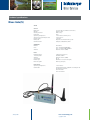
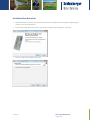
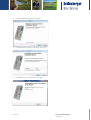
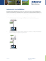
October 2014
www.swstechnology.com
copyright of SLB
Version October 2014
All rights reserved. No part of this publication may be duplicated, stored in a
computerized data file or made public in any form or manner whatsoever,
be it electronic, mechanical, in photocopies, recordings or in any other way,
without prior written permission from
Schlumberger Water Services (Netherlands) BV
t +61 2 9894 4511
e [email protected]
w www.aqualab.com.au
October 2014
www.swstechnology.com
copyright of SLB
WARNING TO USERS IN THE UNITED STATES
Federal Communication Commission Interference Statement 47 CFR Section 15.105(b)
This equipment has been tested and found to comply with the limits for a Class B digital device, pursuant to Part
15 of the FCC Rules. These limits are designed to provide reasonable protection against harmful interference in a
residential installation. This equipment generates, uses and can radiate radio frequency energy and, if not installed
and used in accordance with the instructions, may cause harmful interference to radio communications. However,
there is no guarantee that interference will not occur in a particular installation. If this equipment does cause
harmful interference to radio or television reception, which can be determined by turning the equipment off and on,
the user is encouraged to try to correct the interference by one of the following measures:
Reorient or relocate the receiving antenna.
Increase the separation between the equipment and receiver.
Connect the equipment to an outlet on a circuit different from that to which the receiver is connected.
Consult the dealer or an experienced radio/TV technician for help.
This device (Diver-DXT) complies with Part 15 of the FCC Rules. Operation is subject to the following two conditions:
(1) This device may not cause harmful interference, and (2) this device must accept any interference received,
including interference that may cause undesired operation.
NO UNAUTHORIZED MODIFICATIONS
47 CFR Section 15.21
CAUTION:
This equipment may not be modified, altered or changed in any way without signed written permission from
Schlumberger Water Services (Netherlands) BV. Unauthorized modification may void the equipment authorization
from the FCC and will void the Schlumberger Water Services (Netherlands) BV warranty.
FCC and IC RF Radiation Exposure Statement:
This device complies with FCC and Industry Canada RF radiation exposure limits set forth for the general population
(uncontrolled exposure). This device must be installed to provide a separation distance of at least 20 cm from all
persons and must not be collocated or operating in conjunction with any other antenna or transmitter.
October 2014
www.swstechnology.com
copyright of SLB
IC REQUIREMENTS FOR CANADA
This class B digital apparatus meets all requirements of the Canadian Interference causing equipment regulations.
Cet appareil numérique de la classe B respecte toutes les exigences du règlement sur le matériel brouilleur du
Canada.
This device complies with Industry Canada licence-exempt RSS standard(s). Operation is subject to the following
two conditions: (1) this device may not cause interference, and (2) this device must accept any interference,
including interference that may cause undesired operation of the device.
Le présent appareil est conforme aux CNR d’Industrie Canada applicables aux appareils radio exempts de licence.
L’exploitation est autorisée aux deux conditions suivantes: (1) il ne doit pas produire de brouillage, et (2) l’utilisateur
du dispositif doit être prêt a accepter tout brouillage radioélectrique reçu, même si ce brouillage est susceptible de
compromettre le fonctionnement du dispositif.
CE COMPLIANCE STATEMENT (EUROPE)
This device is in conformity with the EMC directive and low-voltage directive.
October 2014
www.swstechnology.com
copyright of SLB
Table of Contents
1.
Introduction
1
2.
Site Assessment
3
3.
3.1.
3.2.
3.3.
3.4.
3.5.
3.6.
3.7.
3.8.
Diver-NETZ components
Diver dataloggers
DXT cable
Diver-DXT
Diver-Gate(M)
Diver-Gate(S)
Diver-NETZ software
Universal SIM card
Diver-NETZ workflow
4
4
4
4
5
7
9
10
10
4.
4.1.
4.2.
4.3.
4.4.
Preparing for installation
Diver-NETZ Mobile
Diver-NETZ Static
Equipment testing
Setting-up of the Diver-Hub webportal
13
13
14
19
19
5.
5.1.
5.2.
Installing Diver-NETZ in the field
Installing the Diver, DXT cable and Diver-DXT
Installing Diver-Gate(S)
20
20
21
6.
6.1.
6.2.
Collecting data
Diver-NETZ Mobile
Diver-NETZ Static
22
22
22
7.
7.1.
7.2.
7.3.
7.4.
Maintenance and diagnosis Diver-NETZ hardware
Maintaining the Diver-DXT
Maintaining the Diver-Gate(M)
Maintaining the Diver-Gate(S)
Diagnosing the Diver-Gate(S)
23
23
23
23
23
October 2014
www.swstechnology.com
copyright of SLB
Appendices
Appendix I
FAQ Diver-NETZ
Appendix II
DXT cable technical specifications
Appendix III
Diver-DXT technical specifications
Appendix IV
Diver-Gate(M) technical specifications
Appendix V
Diver-Gate(S) technical specifications
Appendix VI
Installation Diver-Gate driver
Appendix VII
Pairing the Diver-Gate(M)
Appendix VIII
Configuration of the Diver-Gate(S) GSM band
Appendix IX
Configuration of the Diver-Gate(S)
Appendix X
Diver-Gate(S) diagnostic tool
October 2014
www.swstechnology.com
copyright of SLB
1.
Introduction
With Diver-NETZ, wireless monitoring of ground and surface water becomes easier, faster and more reliable. DiverNETZ is a wireless method for reading out Diver data and programming Divers. A physical connection between the
read-out equipment and the Diver is no longer necessary.
From wireless field data collection and recording, to project execution in the office, Diver-NETZ is a complete
network of first-class technologies that integrates field instrumentation with the industry’s latest wireless
communication and data management capabilities. All Diver-NETZ components are designed to streamline project
workflows, enabling you to effectively manage your groundwater resources for the long-term.
A functional description of Diver-NETZ technology is presented in the diagram below. A Diver groundwater
datalogger is suspended on a coaxial cable which is connected to a Diver-DXT radio device at the top of the well.
A gateway, Diver-Gate, within a 500 m distance of the well is able to establish a connection with the Diver-DXT and
collect the Diver data wirelessly. Two Diver-NETZ typologies exist. The first typology is a Mobile solution consisting
of a portable Diver-Gate brought in the field by a fieldworker. When the fieldworker is within radio range of the
Diver-DXT the Diver data can be collected wirelessly with a mobile Diver-Gate device which then sends the data
via Bluetooth to mobile device. Downloaded data can then be automatically sent to the office via the GSM/GPRS
network where it can be analyzed and interpreted using desktop software.
The second typology is a Static solution consisting of a Diver-Gate placed permanently in the field within radio
range of the Diver-DXT. At a scheduled interval this Diver-Gate will wirelessly connect to nearby Diver-DXT devices
and collect their data. Through a GSM/GPRS network this data is automatically forwarded to a server. The data will
be visualized by the Diver-Hub portal. Furthermore software programs like Diver-Office and Diver-Office Premium
can be used to interpret, validate or visualize the Diver data from Diver-NETZ.
Any existing network of Divers can be quickly and easily fitted with the Diver-NETZ technology.
October 2014
www.swstechnology.com
copyright of SLB
Page 1
Diver-NETZ Mobile
Diver-DXT
< 500m
DXT cable
Radio
GPRS
Status
Bluetooth
TM
Charge
Diver
Diver-Gate (M)
Diver Software
Diver-Gate(M)
Diver-NETZ Static
Diver-DXT
< 500m
DXT cable
GPRS
Reset
Wake Up
Radio
Status
GSM
Not used
Diver
October 2014
Diver-Gate (S)
Diver-Gate(S)
www.swstechnology.com
copyright of SLB
Diver Software
Page 2
2.
Site Assessment
A pre-installation site assessment is highly recommended when planning and designing a Diver-NETZ installation
(for both the Mobile and Static solution) at a specific site as external and/or environmental factors can influence
the proper functioning of Diver-NETZ. A site assessment can determine the performance level of the Diver-NETZ
system and ensure that the solution will meet all predetermined requirements.
The site assessment should include but is not limited to the following:
• Physical verification of all planned equipment locations;
• Review of mounting options and possible required alterations to existing locations;
• Assessment of interfering and operating frequencies currently in use or ambient in the environment;
• Analysis of Diver-DXT radio signal propagation. The radio coverage is dependent on the well setup and
environmental conditions;
• Analysis of GSM/GPRS coverage (only for Static solution);
• Evaluation of various antenna choices to optimize performance (only for Static solution).
During the site assessment a complete set of Diver-NETZ equipment can be physically brought to the field for
testing purposes. Additionally, other tools (such as a GSM/GPRS signal analyzer) can also be used during the site
assessment.
October 2014
www.swstechnology.com
copyright of SLB
Page 3
3.
Diver-NETZ components
The components of the Diver-NETZ system are:
• Diver datalogger(s)
• DXT cable
• Diver-DXT
• Diver-Gate(M)
• Diver-Gate(S)
• Diver-NETZ software
Additional components of Diver-NETZ are:
• Diver-DXT plastic protective cap available in 2 models
o Cap for 1 Diver-DXT
o Cap for up to 4 Diver-DXT
• Universal SIM card to allow GSM/GPRS communication between Diver-Gate(S) and server
• Watertight protection box to mount Diver-Gate(S)
• External antenna’s for the Diver-Gate(S)
• Batteries for the Diver-Gate(S)
3.1.
Diver dataloggers
Diver dataloggers are cost-effective and reliable instruments to provide long-term, frequent measurements of water
levels, temperature, conductivity and barometric pressure. Divers are ideal for monitoring municipal water supplies,
salt water intrusion, brine storage and migration and environmental monitoring of contamination and remediation
projects. A Diver contains an internal battery and memory. For more information on Diver dataloggers see the Diver
Product Manual.
3.2.
DXT cable
The DXT cable is used to connect a Diver to the Diver-DXT. The DXT cable is mounted to the Diver-DXT housing
using a heavy-duty, water-tight connector that allows you to adjust the cable length as needed. This cable is
available in different lengths (up to 300 meters). For more information see Appendix II.
3.3.
Diver-DXT
The Diver-DXT makes wireless communication possible. The Diver-DXT is placed on top of a well, while the Diver is
installed inside the well below the groundwater level. Both units are connected using a DXT cable, which acts as a
communication link and a mechanical link.
The Diver-DXT contains a low power short-range radio module. The radio module transmits radio signals at a
frequency of 2.405 GHz which is part of the unlicensed industrial, scientific and medical (ISM) radio band. The
transmission power of the radio module is 100 mW, 20 dBm resulting in a radio range of 500 m Line of Sight (L.o.S.).
Furthermore a network identification or network ID is setup in the radio module of the Diver-DXT to ensure the
security of the data and to give the option to create groups of DXTs (for example in areas where more than 1 DiverGate(S) are able to communicate with 1 or more DXTs).
In order to minimize the battery use the radio of the Diver-DXT is deactivated during shipment to the client. The
radio will automatically activate (turn on) when the Diver-DXT is connected to a Diver via a DXT cable. The clock
October 2014
www.swstechnology.com
copyright of SLB
Page 4
of the Diver-DXT will automatically synchronize once a day with the clock of the attached Diver datalogger. After
activation the radio module is awake during the day from 7:00 AM until 23:00 PM, waking up every 14 seconds.
During the night from 23:00 PM to 7:00 AM the radio is asleep and only wakes up once every 5 minutes. The radio
can’t be deactivated (turned off) by the user.
Furthermore, the water-resistant housing contains a datalogger for recording barometric pressure and
temperature. The sampling frequency of the barometric datalogger is fixed at once per hour. The Diver-DXT will also
function without starting the barometric datalogger.
Barometer opening
The Diver-DXT contains an internal battery (battery lifetime 5 years under normal conditions). The battery of the
Diver-DXT can be replaced by the supplier.
The Diver-DXT is not meant to be used under water. The radio performance will decrease when the unit is covered
or surrounded by water. However, sometimes it is difficult to avoid flooding conditions. Therefore the Diver-DXT has
been developed to withstand this situation for a limited time. For more information about Diver-DXT specifications,
see Appendix III.
3.4.
Diver-Gate(M)
The portable Diver-Gate(M) provides the communication between the Diver-DXT and a mobile device via a radio
and Bluetooth connection. The Diver-Gate(M) contains a short-range radio module to communicate with the DiverDXT through the unlicensed industrial, scientific and medical (ISM) radio band at a frequency of 2.405 GHz. The
unit also contains a Bluetooth radio for wireless communication with a mobile device (PDA, smartphone or tablet).
Furthermore the Diver-Gate(M) can be connected through a USB cable to communicate with a PC or laptop.
To communicate with the Diver-DXT the Diver-Gate(M) is carried into the field to a position within radio range of the
Diver-DXT. Through the software on the mobile device or PC the Diver-Gate(M) can be requested to start scanning
for nearby Diver-DXTs. As soon as a connection is set-up between the Diver-DXT and the Diver-Gate(M), the DiverGate(M) is able to download the data from the Diver datalogger and the baro datalogger of the Diver-DXT.
To protect the Diver-Gate(M) against environmental conditions a rubber protection guard is provided. The DiverGate(M) technical specifications can be found in Appendix IV.
October 2014
www.swstechnology.com
copyright of SLB
Page 5
Control functionalities
The following connectors and buttons are available on the Diver-Gate(M):
• On/Off button to turn the device on or off.
• USB port to connect Diver-Gate(M) to a PC via a micro USB cable. Furthermore the USB port is used to
charge the internal battery of the Diver-Gate(M).
• UART port to pair Diver-Gate(M) with mobile device using a dongle.
• Pinhole button not in use (only used by Diver-Gate(S))
Pinhole buttons
On/off button
USB port
UART port
There are four light-emitting diode (LED) indicators to indicate the charge status, the status of the radios (Bluetooth
and the Diver-DXT radio) and the general operating status.
• Radio LED:
o Blinking: indicates scanning for Diver-DXTs
o Continuously on: indicates data exchange between the Diver-Gate(M) and the Diver-DXT
• Status LED:
o Blinking: indicates that the device is active
o Continuously on: indicates booting of the Diver-Gate(M)
• Bluetooth LED:
o Blinking (short on and long off): indicates making a connection or pairing with a mobile device
o Fast blinking (almost continuously on): indicates Bluetooth connection mode
• Charge LED:
o On: indicates charging
o Off: indicates no charging or fully charged (during charging session)
Light Emitting Diodes
The SIM card holder is not in use for the Diver-Gate(M).
October 2014
www.swstechnology.com
copyright of SLB
Page 6
Power options
The Diver-Gate(M) contains an internal rechargeable battery. The battery lifetime of a fully charged battery is
maximum 10 hours under normal conditions. Before taking the Diver-Gate(M) in the field for collecting data it is
advisable to completely charge the battery.
3.5.
Diver-Gate(S)
The static Diver-Gate(S) provides the communication between the Diver-DXT and a server in the office. The DiverGate(S) contains a radio module to communicate with the Diver-DXT through the unlicensed industrial, scientific
and medical (ISM) radio band at a frequency of 2.405 GHz. The unit also contains a 2.5G quad band GSM/GPRS
module to communicate with a FTP server. The Diver-Gate(S) is supplied with a radio and GSM/GPRS antenna.
Other antennas with a SMA connector can also be used.
The Diver-Gate(S) contains an internal clock which runs when the Diver-Gate(S) is connected to a power source.
The clock will determine the time when the Diver-Gate(S) will start scanning for Diver-DXTs and transmit the data
to the server. During configuration the clock is synchronized with the time on the PC. Afterwards the clock will be
synchronized with the UTC time of the server (in case deviation larger than 15 minutes).
The Diver-Gate(S) can be preconfigured by the user to start scanning for nearby Diver-DXT on a fixed wake-up
interval (for example 1x per day) at a fixed time (for example 11:00 AM). As soon as a connection between the DiverGate(S) and the Diver DXT is made, the Diver-Gate(S) will download the data from the baro datalogger of the DiverDXT and from the Diver datalogger. The Diver-Gate(S) downloads only newest data (data not collected before).
Once the data has been collected by the Diver-Gate(S), all collected data will be sent by GSM/GPRS to a server.
Technical specifications of the Diver-Gate(S) can be found in Appendix V.
Control functionalities
The following connectors and buttons are available on the Diver-Gate(S):
• External power supply connector to connect the Diver-Gate(S) to an external power supply.
• USB port to configure Diver-Gate(S).
• UART port: service/debug information (no Diver data transfer).
• SMA connector to connect the radio antenna.
• SMA connector to connect the GSM/GPRS antenna.
• Pinhole buttons:
o Reset – reset/boot configuration to default settings.
o Wake-up – Wake-up Diver-Gate(S) to be able to communicate through USB communication
outside predefined wake-up interval.
October 2014
www.swstechnology.com
copyright of SLB
Page 7
Radio antenna
SMA connector
USB
External power supply
UART port
GSM antenna
SMA connector
Pinhole buttons
There are four light-emitting diode (LED) indicators to indicate the charge status, the status of the radios (GSM/
GPRS and the Diver-DXT radio) and the general operating status.
• Radio
o Blinking: indicates scanning for Diver-DXTs
o Continuously on: indicates data exchange between the Diver-Gate(S) and the Diver-DXT
• Status
o Blinking: indicates that the device is active
o Continuously on: indicates booting of the Diver-Gate(S)
• GSM/GPRS
o Fast blinking: indicates GSM/GPRS connection/communication mode
• Not used
o Led in Diver-Gate(S) not used (only used in Diver-Gate(M) to indicate charging)
SIM card holder
The SIM card holder contains a mini-SIM (2FF) card tray. Micro-SIM (3FF) and/or nano-SIM (4FF) cards can also be
used together with a mini-SIM adapter.
October 2014
www.swstechnology.com
copyright of SLB
Page 8
Light Emitting Diodes
Power options
The Diver-Gate(S) can be powered by the following source:
• Lithium ion batteries
o Non-rechargeable lithium ion 3 cell battery pack (3.6 V per cell)
• Rechargeable batteries with solar panel
o 12 V
• Fixed power supply
o 7-15 V direct current (DC)
Battery pack consisting
of 3 cells
3.6.
Diver-NETZ software
Different software applications can be used to communicate with Diver-NETZ components and/or visualize data:
• Diver-Office: is a comprehensive PC application (Windows) to read out, configure and manage Diver
dataloggers. Furthermore it allows users to read out, configure and diagnose Diver-NETZ hardware.
Diver-Office contains the following Diver-NETZ modules:
o Diver-Gate scan: to scan with a Diver-Gate(M) or Diver-Gate(S) for Diver-DXTs and wireless
collect their data. Furthermore it allows users to configure Diver and Diver-DXT dataloggers.
o Diver-Gate(S) configurator: to configure the Diver-Gate(S) settings (FTP, GSM, wake-up time and
frequency)
o Diver-Gate(S) GSM band configurator: to configure the GSM band of the Diver-Gate(S).
o Diver-Gate(S) diagnostic tool: to diagnose the functioning of a Diver-Gate(S).
• Diver-Mobile: is a user-friendly application for Android or Windows Mobile devices to collect data from
dataloggers in the field.
• Diver-Hub: is a secure online portal that allows users to access and visualize groundwater data from
anywhere in the world. Furthermore the management and visualization of Diver- NETZ data can be
customized for specific client requirements.
October 2014
www.swstechnology.com
copyright of SLB
Page 9
3.7.
Universal SIM card
The Diver-Gate(S) is equipped with a Universal SIM card. In case the client wishes to use his own SIM cards he or
she needs to contact SWS.
3.8.
Diver-NETZ workflow
The sections and illustrations below describe the Diver-NETZ workflows for the Mobile and Static solution in more
detail.
Diver-NETZ Mobile
The Diver-Gate(M) is operated by the user via dedicated software on a mobile device (smartphone, tablet or laptop)
or on a PC/laptop. Through the software the Diver-Gate(M) can be requested to start scanning for nearby DiverDXTs. After the connection is established the software will make it possible for the user to download the data from
the Diver and barologger wirelessly. Diver-Mobile software is used when collecting data with a smartphone or
tablet. Diver-Mobile runs on the following platforms; Windows Mobile and Android. A Bluetooth connection is used
between the Diver-Gate(M) and the smartphone or tablet.
The Diver-Gate(M) can also be operated with Diver-Office software running on a laptop. A USB cable establishes
the connection between the Diver-Gate(M) and the laptop.
Diver-Mobile and Diver-Office software both generate DAT files after collecting the Diver and barologger data.
These DAT files can be imported into the standard Diver management software of SWS (Diver-Office and DiverOffice Premium). When using Diver-Office to collect Diver and barologger data, DAT files are automatically created
and imported into the Diver-Office database. When using Diver-Office Premium it is possible to manually upload the
project data to the Diver-Hub webportal.
Diver-NETZ hardware
Smartphone / tablet (option1)
Diver-Mobile for Windows Mobile
Diver-Mobile for Android
Data Management
DAT
file
Radio
Status
Bluetooth
TM
Charge
Diver-Gate (M)
Diver-Gate(M)
PC / Laptop (option2)
Diver-Office
DAT
file
Diver-Office
Diver-Office Premium
Web portal
Field
October 2014
Office
www.swstechnology.com
copyright of SLB
Page 10
Diver-NETZ Static
The Diver-Gate(S) is configured to scan for nearby Diver-DXT and subsequently Diver data on a predefined basis.
By GSM/GPRS the data is transferred from the Diver-Gate(S) to a server hosted by SWS. Besides time-series data
from the Diver and barologger, the Diver-Gate(S) also transmits a LOG file with information regarding the equipment
status (battery levels, signal strength). This information can be used to manage the equipment deployed in the field.
The SWS server is equiped with a backoffice software tool, called Daemon.
The Daemon is responsible for the following activities:
• Analyze all incoming files uploaded by the Diver-Gate(S). In case data is missing the Daemon will request
the Diver-Gate(S) to collect this information and transmit it to the server.
• Parse time-series data from Diver and barologger into standard Diver files (DAT and MON files) or CSV
files with time series data.
• Directly forward the Diver and barologger timeseries files to a client’s email address or FTP server.
• Program Diver and baro datalogger remotely (start, stop, restart, change location name).
All Diver-NETZ files can be imported into a local database on the SWS server. This database is connected to a
dedicated webportal named Diver-Hub. Clients can access the portal through a secure login to connect to their
Diver-NETZ data. Furthermore, the data can be downloaded directly from this portal.
Diver-NETZ hardware
Data Management
DAT
MON
file
DXT
file
DAT
MON
CSV
file
Di
Diver-Gate(S)
G (S)
LOG
file
LOG
file
Diver-Office
Diver-Office Premium
Web portal
HydroManager
Field
October 2014
Back-office SWS
www.swstechnology.com
copyright of SLB
Client
Page 11
4.
Preparing for installation
This chapter describes the activities to undertake before deploying Diver-NETZ in the field. Diver-NETZ Mobile and
Diver-NETZ Static solutions are discussed separately.
4.1. Diver-NETZ Mobile
Before going into the field, the user needs to make sure the following steps are undertaken:
• Installation of Diver-Office software
• Installation of Diver-Gate driver
• Charging the Diver-Gate(M) battery
• Programming of Diver dataloggers
• Connect Diver to a DXT cable and a Diver-DXT
• Setup network ID in Diver-DXT
• Start barologger Diver-DXT
• Pairing Diver-Gate(M) (only when mobile device is used)
Installation of Diver-Office software
Diver-Office 2014.1 is needed to configure the Diver and Diver-DXT devices. The software can be downloaded
for free from the swstechnology website (www.swstechnology.com). Users who already have installed an older
version of Diver-Office can update directly from within the Diver-Office software.
Installation of Diver-Gate driver
The Diver-Gate driver is a computer program that controls the Diver-Gate(M) (or Diver-Gate(S)) when connected to
a computer through a USB cable. The driver can be downloaded as an executable from the swstechnology website
(www.swstechnology.com). Appendix VI contains the driver installation steps.
Charging the Diver-Gate(M) battery
When charging the Diver-Gate(M) for the first time it is necessary to connect the micro USB cable to a USB charger
(not provided) and not charge the Diver-Gate(M) using a laptop or PC via a micro USB cable. The Diver-Gate(M)
needs to be turned on while the charger is connected. Leave it on until fully charged, indicated by the Charge LED
turning off (approximately 5 hours).
If the Diver-Gate(M) is used on a regular basis the device can be charged using any USB port (PC, car USB charge,
etc.). In this case the Diver-Gate(M) can be turned off while charging. It is also possible to charge the DiverGate(M) continuously. The Bluetooth functionality of the Diver-Gate(M) can be used while continuously charging.
However, this is only possible when using a USB charger (not possible using a USB port).
Programming of Diver dataloggers
The Diver dataloggers can be programmed with a Diver USB reading unit and Diver-Office software. For more
information about programming Diver dataloggers see the Diver manual on the swstechnology website.
Connect Diver to a DXT cable and a Diver-DXT
The Diver is screwed on the bottom connector of the DXT cable and the Diver-DXT is screwed on the top connector
of the DXT communication cable. Through the safety cords the Diver-DXT can be secured to the communication
cable. See illustration for more details.
The radio is deactivated during shipment to the client. The radio will automatically activate (turn on) when the
Diver-DXT is connected to a Diver via a DXT cable. The clock of the Diver-DXT will automatically synchronize once
a day (at midnight) with the clock of the attached Diver datalogger. After activation the radio module is awake
October 2014
www.swstechnology.com
copyright of SLB
Page 12
during the day from 7:00 AM until 23:00 PM, waking up every 14 seconds. During the night from 23:00 PM to 7:00 AM
the radio is asleep and only wakes up once every 5 minutes. The radio can’t be deactivated (turned off) by the user.
Setup network ID in Diver-DXT
A network identification or network ID is a password in the Diver-DXT that allows the Diver-Gate(M) (or DiverGate(S)) to connect to a Diver-DXT. The Diver-DXTs are shipped with a default network ID (1234). It is strongly
recommended to change the default network ID before using the Diver-DXT.
The network ID in the Diver-DXT can be setup with Diver-Office. For more information see the Diver-Office help
section 5.2 (Configuring network settings) and 5.3.1 (Changing Diver-DXT settings).
Start barologger Diver-DXT
The barologger inside the Diver-DXT can be started with the following software:
• Diver-Office 2014.1. For more information see the Help module (section 5.2) within the Diver-Office
software.
• Diver-Mobile. For more information see the Diver-DXT Start section in the Diver-Mobile manual on the
swstechnology website.
It is important to note that the right network ID should be selected within the software to match with the network ID
of Diver-DXT.
Pairing Diver-Gate(M) (only when mobile device is used)
This section is only relevant when the Diver-Gate(M) is used in combination with a mobile device (PDA, smartphone
or tablet) and Diver-Mobile software. The wireless link between the Diver-Gate(M) and the mobile device is based
on a Bluetooth. The Bluetooth link needs to be setup by pairing the device. Appendix VII contains more information
on how to pair the Diver-Gate(M) with a mobile device. In case a PC or laptop is used the Diver-Gate(M) will be
connected physically through a USB cable. Pairing is therefore not needed.
Once the device has been paired, the Diver-Gate(M) will automatically establish a Bluetooth connection to the
particular device when turned on the next time. The mobile device however needs to be within Bluetooth range of
the Diver-Gate(M). The Bluetooth range is approximately 10 m.
The Diver-Gate(M) can only be paired with one device.
4.2.
Diver-NETZ Static
Before going into the field, the user needs to make sure the following steps are undertaken:
• Installation of Diver-Gate driver
• Installation of Diver-Office software
• Programming of Diver dataloggers
• Connect Diver to a DXT cable and a Diver-DXT
• Setup network ID in Diver-DXT
• Start barologger Diver-DXT
• Installation of SIM card
• Configuration of the Diver-Gate(S) GSM band (only for users in the Americas)
• Configuration of the Diver-Gate(S)
• Mounting of the Diver-Gate(S)
• Equipment testing
October 2014
www.swstechnology.com
copyright of SLB
Page 13
•
Setting-up of the Diver-Hub webportal
Installation of Diver-Gate driver
The Diver-Gate driver is a computer program that controls the Diver-Gate(S) (or Diver-Gate(M)) when connected to
a computer through a USB cable. The driver can be downloaded as an executable from the swstechnology website
(www.swstechnology.com). Appendix VI contains the driver installation steps.
Installation of Diver-Office software
Diver-Office 2014.1 is needed to configure the Diver and Diver-DXT devices. The software can be downloaded
for free from the swstechnology website (www.swstechnology.com). Users who already have installed an older
version of Diver-Office can update directly from within the Diver-Office software.
Programming of Diver dataloggers
The Diver dataloggers can be programmed with a Diver USB reading unit and Diver-Office software. For more
information about programming Diver dataloggers see the Diver manual on the swstechnology website.
Connect Diver to a DXT cable and a Diver-DXT
The Diver is screwed on the bottom connector of the DXT cable and the Diver-DXT is screwed on the top connector
of the DXT communication cable. Through the safety cords the Diver-DXT can be secured to the communication
cable. See illustration for more details.
The radio is deactivated during shipment to the client. The radio will automatically activate (turn on) when the
Diver-DXT is connected to a Diver via a DXT cable. The clock of the Diver-DXT will automatically synchronize once
a day (at midnight) with the clock of the attached Diver datalogger. After activation the radio module is awake
during the day from 7:00 AM until 23:00 PM, waking up every 14 seconds. During the night from 23:00 PM to 7:00 AM
the radio is asleep and only wakes up once every 5 minutes. The radio can’t be deactivated (turned off) by the user.
Setup network ID in Diver-DXT
A network identification or network ID is a password in the Diver-DXT that allows the Diver-Gate(S) (or DiverGate(M)) to connect to a Diver-DXT. The Diver-DXTs are shipped with a default network ID (1234). It is strongly
recommended to change the default network ID before using the Diver-DXT. Furthermore it is advisable to setup
different network ID‘s in case a Diver-DXT is within radio range of two or more Diver-Gate(S) devices. This will
make sure that a Diver-DXT can only be scanned and readout by a single Diver-Gate(S).
The network ID in the Diver-DXT can be setup with Diver-Office. For more information see the Diver-Office help
section 5.2 (Configuring network settings) and 5.3.1 (Changing Diver-DXT settings).
Start barologger Diver-DXT
The barologger inside the Diver-DXT can be started with the following software:
• Diver-Office 2014.1. For more information see the Help section within the Diver-Office software.
• Diver-Mobile. For more information see the Diver-Mobile manual on the swstechnology website.
It is important to note that the right network ID should be selected within the software to match with the network ID
of Diver-DXT.
October 2014
www.swstechnology.com
copyright of SLB
Page 14
Installation of SIM card
The SIM card is installed in tray of the SIM card holder. See illustration for more details.
GSM band configuration Diver-Gate(S)
Please be aware this step is only needed once for users in the Americas. With the Diver-Gate(S) GSM band
configurator within Diver-Office the user is able to configure the GSM band of the Diver-Gate(S). On default the
GSM band of the Diver-Gate(S) makes use of Dual-band 900 and 1800 MHz. These GSM bands are used in most
parts of the world. See illustration below. The Diver-Gate(S) GSM band configurator within Diver-Office allows the
user to change the GSM band to 850 and 1900 MHz (mostly used in the Americas) and Quad-band (50 and 1900 MHz
/ 900 and 1800 MHz). Quad-band is however not preferred due to the increase in energy consumption. Appendix VIII
contains more information about changing the GSM of the Diver-Gate(S).
Configuration of the Diver-Gate(S)
With the Diver-Gate(S) Configurator module within Diver-Office the user is able to configure the following DiverGate(S) settings:
• FTP server: Project name, login and password.
• Radio: Number of Diver-DXTs connected to a Diver-Gate(S)
• Network ID: Program network ID in the Diver-Gate(S) to communicate with the Diver-DXTs using the same
network ID
• Wake-up interval: Data transmission rate and time
Other settings like the address of the FTP server, the SIM card settings are already preprogrammed inside the
config file of Diver-Office 2014.1. These settings are based on the SWS server and SWS’s Universal SIM card
settings. When the SWS server and/or the Universal SIM card are not being used, please contact SWS for
information on how to configure these settings in the Diver-Gate(S). Appendix IX contains more information about
configuring the Diver-Gate(S).
October 2014
www.swstechnology.com
copyright of SLB
Page 15
Mounting of the Diver-Gate(S)
The Diver-Gate(S) is not waterproof and therefore in most cases will need to be installed in a watertight protection
box (with or without an external power source, such as a battery pack). The type of protection box depends upon
the location, installation method, available space etc. In some cases external antenna’s need to be integrated in the
protection box. The pictures below contain examples of a mounted Diver-Gate(S).
4.3.
Equipment testing
It is recommended to test the equipment before deploying it in the field by allowing the Diver-Gate(S) to transmit
data to the FTP server. The user can access the FTP server (address: diver-netz.com) with their dedicated login
credentials.
4.4.
Setting-up of the Diver-Hub webportal
SWS will setup the webportal for the client based on the information provided by the client. A Diver-Hub template
is available with all information needed to setup the portal. SWS will provide the login credentials to access the
webportal.
October 2014
www.swstechnology.com
copyright of SLB
Page 16
5.
Installing Diver-NETZ in the field
5.1.
Installing the Diver, DXT cable and Diver-DXT
When deploying both the Diver-NETZ Mobile and/or the Diver-NETZ Static solution in the field, numerous sets of
Divers, DXT cables and Diver-DXTs (assuming they have been connected to each other) must first be installed at a
monitoring point. It is important to ensure that the monitoring points and/or monitoring wells are fit for installation.
Monitoring wells are completed with diverse types of well covers at or above of the surface level, for example:
synthetic flush mounted well covers, synthetic protective covers, metal protective cover, etc. Because the
transmission of the Diver-DXTs radio signal to the Diver-Gate(M) or Diver-Gate(S) can be affected by these well
covers, some well covers may require alterations before the equipment can be installed. For example in the case
of a metal well cover, the Diver-DXT cannot be placed inside the metal enclosure due to the shielding of the radio
signals. Therefore, for this specific case the Diver-DXT has to be placed outside the metal protective cover. This
can be done by drilling holes in the cover and placing the Diver-DXT on top of the cover (a drilling stencil can be
provided by SWS). For this specific situation an extra sturdy synthetic protective cover can protect the Diver-DXT
against vandalism (can be purchased from SWS). Other possible required adjustments to monitoring wells are (also
see illustrations below):
• Additional protective covers to protect the inside of the well from extreme temperatures. Extreme
temperatures can affect the life expectancy and accuracy of the monitoring equipment.
• Protection from permanent or temporary flooding. When a well is flooded or inundated by water the baro
sensor within the Diver-DXT is no longer able to measure the correct barometric pressure. Furthermore, a
flooded well will attenuate the propagation of radio signals from the Diver-DXT.
• Protection from permanent or temporary snow cover. Snow and or ice will attenuate the propagations of
radio signals from the Diver-DXT.
• Furthermore the system should be protected from vandalism, fire, animals, etc.
October 2014
www.swstechnology.com
copyright of SLB
Page 17
Just before deploying the equipment in a well it is recommended to measure the exact cable length (distance
between the membrane of the Diver and the bottom of the Diver-DXT). Furthermore, it is also recommendable to
take a manual measurement (using a dipper) in the well as this information can be later used to verify the proper
functioning and deployment of the system.
Once the monitoring well is deemed fit for installing the Diver, DXT cable and the Diver-DXT the Diver and DXT
cable can be lowered into the well until the Diver-DXT rests on top of the casing. It is important to note that the
space from the top of the casing to the bottom of the well cover needs to be at least 30 mm. If the monitoring well
has more than one casing it is possible to deploy more than one set of Divers, DXT cables and Diver-DXTs in the
same well (there will be no interference between the different Diver-DXTs). To maximize the radio performance of
the Diver-DXT it is important to place the Diver-DXT as closely as possible to the well cover, especially for locations
where the Diver-DXT is potentially placed below ground surface. If required the cable length of the DXT cable can
be fine-tuned (shortened) in the field by using the cable adaptor below the top connector.
Before completing the installation of the Diver, DXT cable and Diver-DXT it is recommended to check the proper
functioning of the equipment by using a Diver-Gate(M) and the appropriate software.
5.2.
Installing Diver-Gate(S)
This section is specific for the Diver-NETZ Static solution. Since the Diver-Gate(S) can connect to the Diver-DXT
and the Diver via radio there are many more installation options for the Diver-Gate(S). Depending on the amount of
Diver-DXTs/Divers allocated to one Diver-Gate(S), the Diver-Gate(S) can be placed either within or outside a well
cover. When communicating with only one Diver-DXT/Diver it is best to install the Diver-Gate(S) as close as possible
to the Diver-DXT. When communicating with more than one Diver-DXT/Diver a strategic position must be chosen for
the Diver-Gate(S) in order for it to be within radio range of the desired Diver-DXTs/Divers.
As with the installation of the Diver, DXT cable and Diver-DXT, it is important to ensure that the monitoring points,
monitoring wells and/or other locations (example: lamp posts) are fit for installation of the Diver-Gate(S). The size
of the mounted Diver-Gate(S) will determine how the Diver-Gate(S) is best installed at the location. Also as with
the installation of the Diver, DXT cable and Diver-DXT, it is important to make sure that the radio and GSM/GPRS
signals are not attenuated and that de Diver-Gate(S) is protected from extreme temperatures, flooding, snow cover,
vandalism, fire, animals, etc.
Before completing the installation of a Diver-Gate(S) the proper functioning of the equipment can be checked by
using Diver-Office to test the radio connection with the Diver-DXTs/Divers via a USB connection between the DiverGate(S) and a PC.
October 2014
www.swstechnology.com
copyright of SLB
Page 18
6.
Collecting data
6.1.
Diver-NETZ Mobile
In order to collect data from the Diver-NETZ Mobile solution it is necessary to visit the field with a Diver-Gate(M)
and a PC equipped with Diver-Office 2012.1 (or higher) or mobile device equipped with Diver-Mobile for Windows
Mobile or Diver-Mobile for Android. The Diver-Gate(M) should be properly charged and firstly paired with the
mobile device or connected with a USB cable to the PC. Furthermore the Diver-Gate(M) should be within radio
range of the Diver-DXTs. When more than one Diver-DXT is within range of the Diver-Gate(M) it is possible to
collect the data from numerous Divers/Diver-DXTs from one location.
6.2.
Diver-NETZ Static
With the Diver-NETZ Static solution data can be collected from the field via GSM/GPRS. The data collection
frequency will depend on the configuration of the Diver-Gate(S). When necessary Divers and/or Diver-DXTs can
be restarted from the office without having to visit the field. With the Diver-NETZ Static solution field visits are only
necessary for troubleshooting, maintenance, manual measurements, etc.
October 2014
www.swstechnology.com
copyright of SLB
Page 19
7.
Maintenance and diagnosis of Diver-NETZ hardware
7.1.
Maintaining the Diver-DXT
The Diver-DXT has a built-in datalogger for the barometric pressure and ambient temperature. The sensor is
located under the upper part of the Diver-DXT (see figure below). This sensor should be in open contact with the air
pressure. Maintenance is needed to keep the area around the location of the sensor clean. Extreme high and low
temperatures, mud, moisture or water could affect the accuracy of the sensor. Clogging of the sensor opening can
result in sensor drift/deviation.
It is not possible to replace the battery of a Diver-DXT in the field. Upon request battery replacement can be
performed by SWS.
7.2.
Maintaining the Diver-Gate(M)
No maintenance is required on the Diver-Gate(M).
7.3.
Maintaining the Diver-Gate(S)
When using a non-rechargeable battery the battery may need to be replaced from time to time. This will depend
on the amount of data being collected and the data transmission frequency of the Diver-Gate(S). When replacing a
non-rechargeable battery firstly disconnect the old battery before connecting the Diver-Gate(S) to a new battery.
The Diver-Gate(S) will then instantaneously start transmitting based on this new data transmission time (the
moment the battery was replaced) and the old configured transmission frequency. If a different data transmission
time is desired (for example the previous data transmission time) the Diver-Gate(S) must be reconfigured using the
Diver-Gate(S) configuration software (see Appendix IX).
No further maintenance is required on the Diver-Gate(S).
7.4. Diagnosing the Diver-Gate(S)
With the Diver-Gate(S) diagnostic tool within Diver-Office the user is able to diagnose a Diver-Gate(S) for a correct
functioning. The diagnostic tool will check the following:
• Configuration settings. These settings are programmed by the user.
• Scanning of Diver-Gate(S) for Diver-DXTs within radio range.
• Collecting of data from the Diver-DXT (Diver-DXT datalogger and Diver datalogger).
• Data transmission by GPRS from the field to the FTP server.
Based upon the outcome of the diagnostic tool the user is able to troubleshoot the Diver-NETZ hardware or change
the installation. Appendix X contains more information about using the Diver-Gate(S) diagnostic tool within DiverOffice.
October 2014
www.swstechnology.com
copyright of SLB
Page 20
Appendix I
October 2014
www.swstechnology.com
copyright of SLB
FAQ Diver-NETZ
Diver-NETZ Mobile and Diver-NETZ Static
How do I store and handle the equipment?
Before installation, the equipment should be stored in a safe place. However, it is important to know what the
effects of storage are for the instrument. The Diver-DXT has a built-in battery which cannot be switched off. This
means that the instrument is always active and consumes energy from the battery. The total battery capacity will
be reduced by approximately 4% per year in storage conditions. Another important storage condition is the ambient
temperature. If the instrument is stored for a long period of time (more than one month) it is best to store the
instrument in a dark place at room temperature.
The instrument is tested for transport conditions according to ASTM D 4169-09 DC 2 (transport simulation test). This
globally accepted standard ensures no damage if the instrument is transported under normal conditions in its own
packaging. Keep the instrument in the original packaging until it is installed in the field. The instrument is also tested
according to MIL-STD-810 and ASTM D 3332 (shock and vibration tests). This test simulates the mechanical shocks
and vibrations during installation of the Diver-DXT. Although the equipment can handle these conditions, it is better
to avoid any abnormal shocks and vibrations if possible. The Diver-DXT has sensors which need to be handled with
care.
What is the radio range between the Diver-Gate(M/S) and the Diver-DXT?
The radio technology of the Diver-DXT and the Diver-Gate(M/S) makes use of the ISM (Industrial, Scientific and
Medical) band. Specifically, the 2.4 GHz radio frequency is used. This radio band is unlicensed, which means that
the frequencies are open for public use and require no registration or payment for usage of the frequency. In order
to comply with the regulations, the output power of the devices is regulated. This regulation may cause limited
range of the radio device. Typically, the radio range of the Diver-DXT device is about 500 meters (1,300 ft) line-ofsight (LOS).
Certain characteristics inherent to the environment where the system is deployed may affect the range of the
radio system. This includes, but is not limited to, rain, snow, fog, large bodies of water, trees, forests, metal well
protective covers, buildings, atmospheric conditions, ambient frequencies, noise, electromagnetic fields and
general conditions of the terrain. Besides, the positioning of the Diver-DXT may affect the range of the radio system
as well.
To maximize the performance of the radio devices, it is recommended to place the Diver-DXT in an area where it is
possible to “see” the device without obstacles in between. This is not mandatory, but improves the performance of
the system. If this condition is not met, the performance of the system may be reduced. We therefore recommend a
site assessment in order to plan and optimize the deployment of devices.
Can I use my existing Diver Data Cables?
Yes, you can use your existing DDC cables. However, the connector of the DDC cable needs to be modified by SWS.
What is the maximum cable length that can be used?
The maximum cable length is 300 meters.
How long does the battery in the Diver-DXT last?
The nominal battery lifespan is 5 years. The battery can be replaced SWS.
October 2014
www.swstechnology.com
copyright of SLB
What are the max/min operating temperatures of the Diver-DXT?
The Diver-DXT operating temperature range is from -20 °C up to +80 °C. The battery life time will decrease when the
device is used below 0°C and/or above 40°C.
How much water can be on top of the Diver-DXT?
The Diver-DXT is designed to withstand up to 1 meter water pressure for 7 days. Please note that the barometric
sensor will not measure the barometric pressure while immersed in water.
Is the old Diver-DXT compatible with the new Diver-DXT?
No, the new Diver-DXT is not compatible with the old Diver-DXT (produced until 2009).
Can I download the barometric data when the Diver-DXT fails?
No. The Diver-DXT must be returned to SWS. In most cases SWS can retrieve your data from the Diver-DXT.
Can other people connect with Diver-NETZ to my Divers?
The Diver-DXT and the Diver-Gate(M) can be protected by a Network-ID.
Diver-NETZ Mobile
How does Diver-NETZ Mobile work?
The figure below depicts the setup of the Diver-NETZ. From left to right: The Diver is suspended on a Diver-DXT
cable with on top the Diver-DXT. The Diver-DXT sends information (data) wirelessly to the Diver-Gate(M). The
Diver-Gate(M) can be wirelessly connected through Bluetooth to a Windows Mobile based device. On this device
the Diver-Mobile application needs to be installed to communicate with the Diver. The Diver-Mobile application will
store the Diver data and can optionally send the data to a FTP server.
What do I need to know about Bluetooth?
Bluetooth is a simple two-way wireless radio technology that allows different devices to connect between
each other without the use of cables or infrared waves. This technology is robust, low-power and low-cost. The
short range radio link provides connectivity between different devices, such as mobile phones, PDAs, PCs and
other electronic devices. It is designed to be used in small range communication and allows voice and data
communication. It operates in the 2.4 GHz radio spectrum. Each class provides a different power output and they
have different communication ranges. This is certified in three different types of standard: Class 1 (100 meters),
Class 2 (10 meter), Class 3 (1 meter). The Diver-Gate(M) has a Class 2 (10 meter) Bluetooth module.
Can I use a mobile phone?
Yes, you can use a mobile phone with Diver-Mobile installed on it. The following hard- and software requirements
are needed to install Diver-Mobile:
• Windows Mobile version 6.1 and higher
• Minimum of 4 GB of Flash memory (SD card)
• Minimum of 128 MB of RAM
• Bluetooth version 2.0 and later
• Data-plan: if you want to send the data to a FTP server
October 2014
www.swstechnology.com
copyright of SLB
Can I use a Pocket-PC?
Yes, you can use a Pocket-PC with Diver-Mobile installed on it.
The following hard- and software requirements are needed to install Diver-Mobile:
• Windows Mobile version 6.1 and higher
• Minimum of 4 GB of Flash memory (SD card)
• Minimum of 128 MB of RAM
• Bluetooth version 2.0 and later
• GSM/GPRS option and a dataplan if you want to send the data to a FTP server
The following hard- and software requirements are needed to install Diver-Mobile:
• Android version 4.0 and higher
• Minimum of 4 GB of Flash memory (SD card)
• Minimum of 128 MB of RAM
• Bluetooth version 2.0 and later
• GSM/GPRS option and a dataplan if you want to send the data to a FTP server
Can I use a laptop?
Yes, you can use a laptop with Diver-Office 2012.1 or higher. The following hard- and software requirements are
needed to install Diver-Office:
• Operating system: Windows XP (SP2 or later, 32 & 64-bit), Windows Vista Business (32 & 64-bit) or
Windows 7 Professional (32 & 64-bit)
• Processor: Pentium 4-compatible processor or higher, 1.6 GHz or higher recommended
• Hard Disk: 2GB (3GB or more recommended)
• Memory: 1GB RAM (2GB or more recommended)
• Serial communication: One available USB port or one Serial COM port
• Screen resolution: 1024 x 768, color: 16 bits
• Microsoft SQL Server Compact Edition 3.5 SP2 (included in installation package)
In what languages is Diver-Mobile available?
The Diver-Mobile application is available in the English language.
Can I use my own FTP server?
Yes. In the Diver-Mobile application you can set the address of the FTP server.
What are the requirements for a FTP server?
The FTP server must be a standard none secured FTP server.
I do not have a Bluetooth connection between the Diver-Gate(M) and the Mobile Device?
• Please follow the next steps:
• Check the Bluetooth LED of the Diver-Gate(M). This LED should blinking fast (almost continuously on)
• If the Bluetooth LED doesn’t blink at all (not even for a short period) the Diver-Gate(M) has to be paired.
Follow the Bluetooth pairing procedure
• If the Bluetooth LED does blink but will not go into an almost continuous mode (indicating the Bluetooth
connection), the Bluetooth of the mobile device is not visible to the Diver-Gate(M). Change the Bluetooth
settings of the mobile device to “Always Visible”
• If the Bluetooth LED indicates a Bluetooth connection but the application cannot find the Diver-Gate(M) it
is possible that the serial port check box in the Bluetooth settings is not ticked. Tick this box (enable serial
port) and try again.
October 2014
www.swstechnology.com
copyright of SLB
I don’t have Bluetooth connection between the Diver-Gate(M) and a mobile device anymore but it worked in the
past?
Check if Bluetooth is enabled. Check the Bluetooth status on your device (PC, mobile device). Some devices also
have a switch that shuts down all radios (WiFi and Bluetooth). Make sure this switch is on.
I do not have a radio connection between the Diver-Gate(M) and the Diver-DXTs?
Please follow the next steps:
• If you have no connection after 30 seconds you may be out of radio range. Try to move closer to the DiverDXT and re-establish the connection. Try this a few times from different locations.
• From 07:00 PM to 23:00 PM the radio of the Diver-DXT will be in sleep mode to save battery capacity.
Making a connection can therefore take more time (longer than 5 minutes).
• Make sure you use the correct Network ID. For selecting the correct Network ID see the Diver-Mobile
Manual.
• The radio connection can be distorted by Wifi signals transmitting at the same radio band of Diver-NETZ
• Check if the Radio LED on the Diver-Gate(M) is blinking during scanning and continuously on during data
transfer. If not, the problem could be the Diver-Gate(M).
Diver-Mobile is unresponsive. What should I do?
Go to Task Manager and shut down the Diver-Mobile application or give your field device a soft reset. How to do
this is described in the user manual of the field device.
How long does the battery in the Diver-Gate(M) last and how can it be recharged?
The battery in the Diver-Gate(M) can be used for 10 hours without the need for recharging. The Diver-Gate(M) is
recharged through the USB port on the Diver-Gate(M).
I fully charged the battery but when I turn on the Diver-Gate(M) all the LEDs go off after a few seconds?
When a Diver-Gate(M) with fully charged battery turns off or if you unplug and plug the internal battery, it is
necessary to follow the following procedure:
• Connect the USB cable to the Diver-Gate(M)
• Switch on the Diver-Gate(M)
• The status LED should start blinking for at least 30 seconds
• After several minutes the battery level is calibrated with the battery. You can leave the device on during
charging
Can I start/stop/reprogram a Diver with Diver-NETZ?
Yes, this can be done with Diver-Office 2012.1 and Diver-Pocket (when version 2012 is available).
What to do when you get an error while starting Diver-Mobile?
If the Diver-Mobile application generates the following error “No Diver-Gate(M) found”, there is no Bluetooth
connection between the Diver-Gate(M) and a mobile device. See FAQ “I do not have a Bluetooth connection
between the Diver-Gate(M) and the mobile device”.
October 2014
www.swstechnology.com
copyright of SLB
Diver-NETZ Static
Can I use my own FTP server?
Yes, this is possible. In the Diver-Gate(S) you can configure the address of your own FTP server. Schlumberger
Water Services can provide you with information regarding the requirements and steps to undertake this.
What are the requirements for a FTP server?
The FTP server must be a standard none secured FTP server.
What GSM frequency bands are used by the Diver-Gate(S)?
The GSM module of the Diver-Gate(S) makes use of the following frequency bands 850/900/1800/1900 MHz (Quad
band).Frequency band 900 and 1800 MHz are used in most parts of the world: Europe, Middle East, Africa, Australia,
Oceania (and most of Asia). In North America, GSM operates on the primary mobile communication bands 850 MHz
and 1900 MHz. In South and Central America some countries use 850 en 1800 MHz.
Which mobile data services are supported by the Diver-Gate(S)?
The GSM module of the Diver-Gate(S) makes use of GPRS services (2.5G). GPRS is a wireless data transfer protocol
that is used to connect mobile devices to the internet. It operates through the cellular network. To successfully use
the Diver-Gate(S) device the telecom provider needs to support GPRS services.
Which SIM cards can be used?
By default SWS makes use of universal SIM cards. Universal SIM cards grant GSM services in nearly every country
in the world generally at lower costs than other SIM cards. SWS can provide a list of GSM providers supported by
the universal SIM cards in a specific country. Please be aware that the GSM provider still needs to support GPRS to
successfully deploy Diver-NETZ Static. See also previous question.
Can I use my own local SIM card?
Yes, this is possible. SWS can provide you with information regarding the requirements and needed steps to
configure the Diver-Gate(S) with local SIM cards.
Can I start/stop/reprogram a Diver with Diver-NETZ?
Yes, this can be done remotely. Schlumberger Water Services can provide you additional information.
I do not have a radio connection between the Diver-Gate(S) and the Diver-DXTs?
Please follow the next steps:
• From 07:00 PM to 23:00 PM the radio of the Diver-DXT will be in sleep mode to save battery capacity.
Making a connection can therefore take more time (longer than 5 minutes).
• Make sure you use the correct Network ID. For selecting the correct Network ID see the Diver-Mobile
Manual.
• The radio connection can be distorted by Wifi signals transmitting at the same radio band of Diver-NETZ
• Check if the Radio LED on the Diver-Gate(S) is blinking during scanning and continuously on during data
transfer. If not, the problem could be the Diver-Gate(S).
October 2014
www.swstechnology.com
copyright of SLB
How can I power my Diver-Gate(S)?
The Diver-Gate(S) needs to be connected to an external power supply. This can be a lithium battery pack or a 12 V
solar panel with a rechargeable battery.
No data is being transmitted by GPRS from the Diver-Gate(S) to the FTP server?
Please run the Diver-Gate(S) diagnostic tool (paragraph 7.4 of this manual).
The issue could be related to the following:
• Lack of power. Make sure the external power is connected correctly to the Diver-Gate(S) and LED
indicators start blinking when waking up the Diver-Gate(S).
• SIM card not properly fitted. In this case the Diver-Gate(S) can not make a connection with the GSM
network. Make sure the SIM card is properly fitted into the SIM card holder. The SIM card needs to be
locked by sliding the SIM card holder into the fitting.
• Configuration settings incorrect. Make sure the Diver-Gate(S) is properly configured (FTP settings, SIM
card settings, network ID, wakeup time etc). The configuration of the Diver-Gate(S) can be checked in the
overview LOG file created by the Diver-Gate(S) Configuration tool.
• No GPRS coverage due to a lack of GPRS signal or due to a lack of data subscription with your own
local SIM card. Please check the strength of the GPRS signal. This information can be retrieved from
a communications log of the Diver-Gate(S). Please contact Schlumberger Water Services for more
information.
October 2014
www.swstechnology.com
copyright of SLB
Appendix II
October 2014
www.swstechnology.com
copyright of SLB
Specifications
Technical
specifications
DXT cable
AS2xxx*
Protection
Length accuracy
Cable stretch
Available lengths
IP67**
±1% (≥1 cm)
<1%
1, 5, 10, 15, 20, 30, 40, 50, 60, 80, 100, 150, 200,
250, 300 m
300 m
up to 40% of maximum length
-20°C to 80°C
nylon PA6, fibreglass-reinforced (30%)
polyurethane (PU)
Maximum length
Cable length adjustment
Temperature range
Material of connectors
Material of cable insulation
Cable length according to customer specifications.
* AS2xxx (xxx is length in meters). Example: AS2001 is 1 m and AS2015 is 15 m.
** Only if connected to Diver-DXT.
January 2014
105 mm
D = 23.3 mm
110 mm
D = 49 mm
D = 22 mm
Specific length of the cable
97 mm
D = 3.2 mm
D = 18 mm
44 mm
Effective working length of the cable (Baro-, Cera-, Mini- en Micro-Diver)
Specific length of the cable
89 mm
Effective working length of the cable (CTD-Diver)
28.5 mm
Diver-DXT dimensions
www.swstechnology.com
copyright of SLB
Appendix III
October 2014
www.swstechnology.com
copyright of SLB
Technical specifications
Diver-DXT
AS338
General
Diameter
Length
Weight
Housing material
Protection
Operating temperature
Storage / transport temperature
Battery life*
Battery
Battery replacement
Instrument interface
Datalogger barometer
Storage capacity
Measuring interval
Measuring method
Clock accuracy
Recorded parameter
Barosensor
Sensor
Range
Accuracy
Resolution
Absolute maximum pressure (MP)
Absolute maximum burst pressure
Long term stability
Temperature
Sensor
Range (FS)
Accuracy
Resolution
Radio
Radio frequency
Transmit power
Scan-for-host period
Radio range
Data encryption
January 2014
Ø 49-23 mm
141 mm (including chassis connector)
Approx. 84 gr
High Heat ABS Polylac® casing, Viton® and
MBR o-rings, Cu Zn/Ni connector
IP67 (for max 7 days )
-20 °C to 60 °C (within specs)
-40 °C to 85 °C (affects battery life time)
5 years @ OT, depending on operation and max
3,000 connections with Diver-Gate, 30,000
memory block reads
Non-rechargeable lithium-thionyl chloride
(3,600 mAh)
By manufacturer
Diver-DXT cable with Baro-Diver, Mini-Diver,
Micro-Diver, Cera-Diver and CTD-Diver
24,000 measurements (non-volatile memory)
60 min
Fixed
Automatic synchronisation with attached Diver
(once a day)
Barometric pressure (cmH2O) and temperature
(°C)
Piezo resistive silicon micro machined sensor
400 -1,150 cmH2O
±1 cmH2O (typ.) @OT
±2 cmH2O (max.) @OT
0.1 cmH2O
1.5 bar (absolute)
2 bar (absolute) @1sec
±1 cmH2O/year (typ.) @OT
Silicon temperature sensor
-20 °C to 80 °C
±1 °C (typ.) @OT
±3 °C (max.) @OT
0.1 °C
2.405 GHz (channel 11)
100 mW, 20 dBm
14 sec (07.00AM-11.00PM), 300 sec
(11.00PM-07.00AM)
500 meter L.o.S. (Line of Sight)
AES-key (16 bytes)
www.swstechnology.com
copyright of SLB
Technical specifications
Diver-DXT
Environment
Operating temperature
Operating elevation range
Pressure
Random vibration
Mechanical shock
Transportation
Certification
-20 °C to 60 °C (within specs)
-300 to 5,000 m MSL (mean sea level)
Up to MP (in air)
MIL-STD-810: 10 Hz, 0.02 g2/Hz ,
60-1,000 Hz 0.02 g2/Hz ,
1,000-2,000 Hz 6 dB/oct
ASTM D 3332: Free-fall drop 0.1 to 0.7 m
(500 g @ 2 ms)
According to ASTM D 4169-08, DC2
(outside of western Europe by truck/air/boat)
CE: R&TTE Directive 1999/5/EC according to the
harmonized standards
FCC: V43DIVERDXT2
IC: 7675A-DIVERDXT2
* The Diver-DXT is always active. The leakage current of internal battery is mostly depending
on temperature. If stored or transported for a longer period at elevated temperatures
battery life time will be affected
January 2014
www.swstechnology.com
copyright of SLB
Appendix IV
October 2014
www.swstechnology.com
copyright of SLB
Technical specifications
Diver-Gate(M)
AS345
General
Dimension
Weight
Housing material
Protection
Operating temperature
Storage / transport temperature
Power supply
Battery life
Communication
138 x 62 x 34 mm (with protection guard)
Approx. 181 gr
ABS casing
IP52 (with protection guard)
-20 °C to 60 °C (within specs)
-40 °C to 85 °C
Internal rechargeable lithium ion battery,
charged through USB port
10 hours in Bluetooth connection mode
USB port, Bluetooth®, UART
Bluetooth
Module
Antenna
Fully qualified Bluetooth® V2.1 + EDR, Class 2
Internal ceramic antenna
Radio
Radio frequency
Transmit power
Antenna
Scan period
Radio range
Data encryption
2.405 GHz (channel 11)
100 mW, 20 dBm
Internal ceramic antenna
30 sec
500 meter L.o.S. (Line of Sight)
AES-key (16 bytes)
Environment
Operating temperature
Certification
January 2014
-20 °C to 60 °C
CE: R&TTE Directive 1999/5/EC according to the
harmonized standards
FCC: RI7BG864
IC: 5131A-BG864
www.swstechnology.com
copyright of SLB
Appendix V
October 2014
www.swstechnology.com
copyright of SLB
Technical specifications
Diver-Gate(S)
AS340
General
Dimension
Weight
Housing material
Protection
Operating temperature
Storage / transport temperature
Power supply
Battery life
Communication
GSM/GPRS
Module
Class
Antenna
Quad band
Class 4 (2W) @ 850/900 MHz
Class 1 (1W) @ 1800/1900 MHz
External antenna (SMA)
Radio
Radio frequency
Transmit power
Antenna
Scan period
Radio range
Data encryption
2.405 GHz (channel 11)
100 mW, 20 dBm
External antenna (SMA)
30 sec
500 meter L.o.S. (Line of Sight)
AES-key (16 bytes)
Environment
Operating temperature
Certification
January 2014
134 x 58 x 30 mm (without connectors)
Approx. 144 gr
ABS casing
none
-20 °C to 60 °C (within specs)
-40 °C to 85 °C
7-15 V DC
Depends on external battery used
USB port, GSM/GPRS, UART
-20 °C to 60 °C
CE: R&TTE Directive 1999/5/EC according to the
harmonized standards
FCC: RI7GG864
IC: 5131A-GG864
www.swstechnology.com
copyright of SLB
Appendix VI
October 2014
www.swstechnology.com
copyright of SLB
Installation Diver-Gate driver
1.
Download the driver from the swstechnology website (Link: http://www.swstechnology.com/dataloggers/
wireless-accessories/diver-gate)
2.
Run the executable (Diver-Gate_Drivers_Setup.exe). A Setup window will appear. Click Next
3.
Driver is ready to be installed. Click Install
October 2014
www.swstechnology.com
copyright of SLB
4.
Installation Wizard will appear. Click Next
5.
To complete the installation of the driver click Finish
6.
To complete the setup of the driver click Finish
October 2014
www.swstechnology.com
copyright of SLB
Appendix VII
October 2014
www.swstechnology.com
copyright of SLB
Pairing the Diver-Gate(M)
The following steps illustrate how to pair a Diver-Gate(M) with a Windows Mobile device to enable the Bluetooth
connection.
• Attach the pairing dongle to the Diver-Gate(M).
• Turn on the Diver-Gate(M).
• Activate the Bluetooth function on a mobile device (usually found under the Settings menu) and set it to
be discoverable or visible to other devices.
• Open the Bluetooth connection settings and start searching for nearby Bluetooth devices.
• Remove the pairing dongle.
• After retrieving a list of nearby Bluetooth devices, select the Diver-Gate(M) (name is
SWSGW_1414xxxxxxxx) (see example figure 1) and press Next.
• Enter passcode “1234” and press OK (see example figure 2).
• After the passcode is accepted, the name of the Diver-Gate(M) is displayed under disconnected devices
(see example figure 3).
• Select Diver-Gate(M) to modify its settings.
• Activate “Serial port” (see example figure 4).
• The Diver-Gate(M) will automatically restart (Status LED will be continuously on for 5 to 10 seconds).
• After approximately 30 seconds the Bluetooth LED will turn on to indicate a Bluetooth connection.
October 2014
www.swstechnology.com
copyright of SLB
Appendix VIII
October 2014
www.swstechnology.com
copyright of SLB
Configuration of the Diver-Gate(S) GSM band
With the Diver-Gate(S) GSM band configurator within Diver-Office the user is able to configure the GSM band of
the Diver-Gate(S). On default the GSM band of the Diver-Gate(S) makes use of Dual-band 900 and 1800 MHz. These
GSM bands are used in most parts of the world. The Diver-Gate(S) GSM band configurator within Diver-Office
allows the user to change the GSM band to 850 and 1900 MHz (mostly used in the Americas) and Quad-band (50 and
1900 MHz / 900 and 1800 MHz).
The following steps give more information about configuring the GSM band of the Diver-Gate(S):
1.
Connect Diver-Gate(S) with the PC using the mini USB cable (this cable is not provided by SWS).
2.
Plug the battery (or power supply) in the Diver-Gate(S). In case the battery is already connected wakeup
the Diver-Gate(S) by pressing the wakeup pinhole button.
•
•
•
•
•
•
•
•
•
•
•
•
•
•
•
October 2014
www.swstechnology.com
copyright of SLB
3.
After the Diver-Gate(S) lights are blinking start Diver-Office and open the Diver-Gate(S) GSM band
configurator.
4.
Select the USB communication port and click Next to continue.
5.
Connect Diver-Gate(S) with the PC using the COM cable (this cable is not provided by SWS). Do not
remove the USB cable.
October 2014
www.swstechnology.com
copyright of SLB
6.
Select the COM port.
7.
Select the GSM radio band and click Next to continue.
8.
A popup message will appear if the GSM band is configured successfully. Restart the Diver-Gate(S) by
repowering the device (unplug and plug power source). Click Ok to close the Diver-Gate(S) GSM band
configurator.
October 2014
www.swstechnology.com
copyright of SLB
Appendix IX
October 2014
www.swstechnology.com
copyright of SLB
Configuration of the Diver-Gate(S)
The Diver-Gate(S) can be configured in two modes: Simple mode and Advance mode. Within the Simple mode the
default settings will be programmed inside the Diver-Gate(S). This mode will be used when using the server and
Universal SIM card provided by Schlumberger Water Services. The Advance mode is used to configure all DiverGate(S) settings.
Simple mode
The following steps give more information about configuring the Diver-Gate(S):
1.
Connect Diver-Gate(S) with the PC using the mini USB cable (this cable is not provided by SWS).
2.
October 2014
Plug the battery (or power supply) in the Diver-Gate(S). In case the battery is already connected wakeup
the Diver-Gate(S) by pressing the wakeup pinhole button.
www.swstechnology.com
copyright of SLB
3.
Start Diver-Gate(S) Configurator software application. Select Simple mode, click Next to continue.
4.
Select the correct USB COM port to setup a connection with the Diver-Gate(S). Searching for a DiverGate(S) is possible both manually and automatically. Manual option assumes selecting the COM port
where the Diver-Gate(S) is connected. Alternatively, select the automatic mode to search for the device.
Click on the Refresh button when the Status LED starts blinking. When the Diver-Gate(S) is recognized,
click Next to continue.
5.
This window gives information about the device (firmware version of the Diver-Gate(S), hardware version
of the Diver-Gate(S), radio firmware of the Diver-Gate(S) and the battery capacity). Click Next to continue.
October 2014
www.swstechnology.com
copyright of SLB
6.
This window allows you to configure the project name (destination folder) and the login credentials on
the FTP server. These settings will be provided by SWS. Click the tick box to fill in the login and password
settings (only once). Click Next to continue.
7.
This window enables you to specify the Network ID applied to the specific Diver-Gate(S). After filling in
the needed information, click Next.
October 2014
www.swstechnology.com
copyright of SLB
8.
This window enables you to set up the radio settings of DXT (number of Diver-DXT connected to a
Diver-Gate(S)). Based on this number the software will automatically determine the recommended radio
settings. The maximum number of Diver-DXTs connected to a Diver-Gate(S) is 17. Click Next to continue.
9.
The following window enables you to set-up the wakeup settings (data transmission frequency and wakeup time) of the Diver-Gate(S). Click “Next”.
October 2014
www.swstechnology.com
copyright of SLB
10.
The configuration of the Diver-Gate(S) is finished. By selecting Create Overview’ a LOG file will be created
with an overview of all configuration settings applied to the Diver-Gate(S).
11.
Once the Status LED on the Diver-Gate(S) stops blinking the configuration tool can be closed by clinking
Exit. The mini USB cable can now be disconnected from the Diver-Gate(S).
October 2014
www.swstechnology.com
copyright of SLB
Advance mode
The following steps give more information about configuring the Diver-Gate(S):
1.
Connect Diver-Gate(S) with the PC using the mini USB cable (this cable is not provided by SWS).
2.
Plug the battery (or power supply) in the Diver-Gate(S). In case the battery is already connected wakeup
the Diver-Gate(S) by pressing the wakeup pinhole button.
3.
Start Diver-Gate(S) Configurator software application. Select Advance mode, click Next to continue.
October 2014
www.swstechnology.com
copyright of SLB
4.
Select the correct USB COM port to setup a connection with the Diver-Gate(S). Searching for a DiverGate(S) is possible both manually and automatically. Manual option assumes selecting the COM port
where the Diver-Gate(S) is connected. Alternatively, select the automatic mode to search for the device.
Click on the Refresh button when the Status LED starts blinking. When the Diver-Gate(S) is recognized,
click Next to continue.
5.
This window gives information about the device (firmware version of the Diver-Gate(S), hardware version
of the Diver-Gate(S), radio firmware of the Diver-Gate(S) and the battery capacity). Click Next to continue.
October 2014
www.swstechnology.com
copyright of SLB
6.
This window allows you to configure the FTP address, port and project folder (destination folder) of the
FTP server. Click the tick box to fill in the login and password settings (only once). Click Next to continue.
7.
This window allows you to configure the Daemon settings (backoffice software running on the server).
The following parameters need to be provided: server address and port. Click Next to continue.
October 2014
www.swstechnology.com
copyright of SLB
8.
This window enables you to specify the Network ID applied to the specific Diver-Gate(S). Furthermore by
clicking the advanced tick box the user is able to fill in the radio channel (default 11) and encryption key.
SWS can provide additional information regarding the use of the encryption key. After filling in the needed
information, click Next.
9.
This window enables you to set up the radio settings of DXT. In simple mode the number of Diver-DXT
connected to the Diver-Gate(S) need to be filled in. Based on this number the software will automatically
determine the recommended radio settings. In the advanced mode a user can select the radio settings
himself. The maximum number of Diver-DXTs connected to a Diver-Gate(S) is 17. Click Next to continue.
October 2014
www.swstechnology.com
copyright of SLB
10.
The SIM pin of the card can be filled in the SIM settings window. On default the SIM pin is 0000. Click
“Next”.
11.
October 2014
The following window enables you to set-up the APN settings of the SIM card. The following options are
available: Universal SIM (provided by SWS), automatic selection of SIM card settings and finally the user
can fill in the APN settings manually when using a local SIM card. Click “Next”.
www.swstechnology.com
copyright of SLB
12.
The Data collection window enables you to select the data collection method for a data transmission
sequence. NoData will only transmit a LOG file containing household data, and no data from the
Diver and Diver-DXT datalogger will be transmitted. LastData will send new data (data which has not
been transmitted before) and AllData will transmit all data during each transmission sequence. SWS
recommends to use the LastData method. Click “Next”.
13.
The following window enables you to set-up the wakeup settings (data transmission frequency and wakeup time) of the Diver-Gate(S). Click “Next”.
October 2014
www.swstechnology.com
copyright of SLB
14.
The configuration of the Diver-Gate(S) is finished. By selecting Create Overview’ a LOG file will be created
with an overview of all configuration settings applied to the Diver-Gate(S).
15.
Once the Status LED on the Diver-Gate(S) stops blinking the configuration tool can be closed by clinking
Exit. The mini USB cable can now be disconnected from the Diver-Gate(S).
October 2014
www.swstechnology.com
copyright of SLB
Appendix X
October 2014
www.swstechnology.com
copyright of SLB
Diver-Gate(S) diagnostic tool
With the Diver-Gate(S) diagnostic tool within Diver-Office the user is able to diagnose a Diver-Gate(S) for a correct
functioning.
The following steps give more information about the Diver-Gate(S) diagnostic tool:
1.
Connect Diver-Gate(S) with the PC using the mini USB cable (this cable is not provided by SWS).
2.
October 2014
Connect Diver-Gate(S) with the PC using the COM cable (this cable is not provided by SWS). Do not
remove the USB cable.
www.swstechnology.com
copyright of SLB
3.
Plug the battery (or power supply) in the Diver-Gate(S). In case the battery is already connected wakeup
the Diver-Gate(S) by pressing the wakeup pinhole button.
4.
After the Diver-Gate(S) lights are blinking start Diver-Office and open the Diver-Gate(S) diagnostic tool.
October 2014
www.swstechnology.com
copyright of SLB
5.
Select the COM port and click Start. The diagnostic tool will start with an actual data transmission.
6.
In case a warning symbol appears the user can click on the symbol to get additional information.
October 2014
www.swstechnology.com
copyright of SLB
7.
After the actual data transmission is finished, the user can save the COM log file.
8.
Click Close to close the diagnostic tool. A popup message will appear to ask the user to put the DiverGate(S) back to sleep. Click Yes. Disconnect the cables after all light stop blinking and are turned off.
October 2014
www.swstechnology.com
copyright of SLB