1
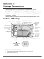
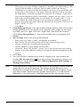
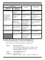
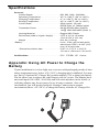
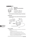
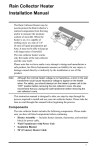
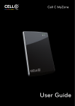
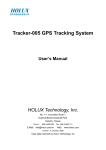
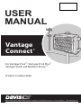
Distributed by MicroDAQ.com, Ltd. www.MicroDAQ.com (603) 746-5524 USER MANUAL Vantage Connect R ™ For Vantage Pro2™, Vantage Pro2 Plus™, Vantage Vue R and Weather Envoy ™ Product number 6620 R Davis Instruments, 3465 Diablo Avenue, Hayward, CA 94545-2778 U.S.A. • 510-732-9229 • www.davisnet.com Distributed by MicroDAQ.com, Ltd. www.MicroDAQ.com (603) 746-5524 EC-Declaration of Conformity Directive 1999/5/EC (R&TTE Directive) Manufacturer / responsible person: Davis Instruments Perry Dillon ,Compliance Engineer Address: 3465 Diablo Ave., Hayward, CA 94545 USA Declares that the product: Vantage Connect, models 6620OV, 6620CG, 6620SOV, 6620CS and 7315.234 Complies with the essential requirements of Article 3 of the R&TTE 1999/5/EC Directive, if used for its intended use and that the following standards have been applied: 1. Health (Article 3.1.a of the R&TTE Directive) Applied standard(s)(EC recommendation 1999/519/EC) 2. Safety (Article 3.1.a of the R&TTE Directive) Applied standard(s)(EN 60950-1:2006/A11:2009/A1:2010/A12:2011) 3. Electromagnetic compatibility (Article 3.1.b of the R&TTE Directive) Applied standard(s)EN301489-1, V1.8.1, EN301489-7, V1.3.1, 4. Efficient use of the radio frequency spectrum (Article 3.2 of the R&TTE Directive) Applied standard(s)EN301511, V9.0.2 The technical documentation relevant to the above equipment will be held at: Davis Instruments at 3465 Diablo Ave, Hayward CA 94545 0 Distributed by MicroDAQ.com, Ltd. www.MicroDAQ.com (603) 746-5524 Welcome to Vantage Connect (6620) Vantage Connect allows you to automatically upload data from a Davis Vantage Pro2™ , Vantage Vue®, or other Vantage Pro2-compatible sensor suite to WeatherLink.com through the cellular network. With your own online account and a data plan, you can receive alarm e-mails when preset weather conditions occur, view data online or through a smartphone, or even download data into your PC with WeatherLink® software. Vantage Connect is available in different packages depending on country of use. Contents of Package Weather station status LED Cell modem antenna Receptacle for cabled ISS Cell network status LED Cover for cell modem and weather receiver Main power jack Weather receiver antenna Main power cable Status LED on/off button Main power cable (back) To solar panel Battery power cable (middle) Solar power cable (front) 6-volt, 12-amp-hr battery Oval split grommet (in cabled versions only) Battery cable tie Battery platform Charging Circuit Board WeatherLink software CD The package contains the following: • • Vantage Connect in weather-proof shelter with 5-watt solar panel WeatherLink software CD 1 Distributed by MicroDAQ.com, Ltd. • www.MicroDAQ.com (603) 746-5524 Hardware kit (as shown below) U-Bolts 1/4" Lock Washers 1/4" x 1 1/4" Lag Screws 1/4" Hex Nuts Backing Plates #6 x 3/8 Screws (not needed) Requirements • • • A Davis Vantage Pro2 or Vantage Vue integrated sensor suite (ISS) or other Vantage-Pro2 transmitting station (all sold separately) GSM/GPRS cellular network coverage in the area Vantage Connect service plan (sold separately) Register & Configure Your Vantage Connect Purchase a Vantage Connect Service Plan. Vantage Connect requires an annual service plan. Choose #6632, 6634, or 6636 in the version appropriate for your region (US, A, B, or C). Each plan offers a different update interval (5, 15, or 60 minutes). For more information see your Davis reseller or purchase a plan during your registration process on WeatherLink.com. After purchase, you will receive an e-mail with an Activation Code that you will use to register online. Register Online Note: Register your Vantage Connect online and wait 5 to 10 minutes BEFORE you power it up to avoid a delay in uploading data. If you already powered up before registering, remove power from the Vantage Connect, register, then repower. 1. When you receive the e-mail with the Activation Code, follow the instructions in the e-mail. (Or, go to www.weatherlink.com; click on Register. Select the Vantage Connect option.) 2. Read and agree to the Terms of Use. 2 Distributed by MicroDAQ.com, Ltd. www.MicroDAQ.com 3. Enter the DID and KEY located on the sticker on the cover of this manual and on the sticker inside the Vantage Connect shelter. (603) 746-5524 DID: 0012746AAS00 KEY: 123456 4. Create and enter a user name and password, and enter your e-mail address to create a new user account. Note: Your user name will become part of your web page’s URL. For example if your user name is JohnSmith, your URL will be www.weatherlink.com/user/JohnSmith 5. 6. 7. 8. 9. Enter your time zone and indicate your Daylight Saving Time preference. Enter the Activation Code received in the e-mail. Click Continue with Registration. Agree to the Service Agreement. Click Create Account. Configure and Set Up Your Vantage Connect You will need to know the transmitter IDs of each transmitting station before you configure your Vantage Connect. Follow the prompts to enter setting and configuration: 1. Reporting Stations & Units of Measure • • • Enter the transmitter ID number of each of the transmitters that will be reporting to your Vantage Connect (up to 8). Choose a station type for each. (For example, Vantage Pro2 ID: 1, Leaf and Soil Moisture Station: ID 2.) If using repeaters, check the “Enable Repeaters” box and choose the final repeater’s ID letter for each transmitter using repeaters. Choose your preferred units. Click Save. 2. Device Settings • • • • For accurate barometric pressure data, enter the elevation at which your Vantage Connect will be mounted. Fine tune this sensor by entering the local barometric pressure reading. (Sources of this information include your local airport or radio station) Select your anemometer and rain collector types. For accurate year-to-date rain data, enter the year-to-date rainfall as of today, and when your rain season starts. Station Alarms (Optional): Set alarms for high and low weather conditions. Vantage Connect will send up to 20 (counting both activate and deactivate) alarm notifications per day when these conditions exist. 3 Distributed by MicroDAQ.com, Ltd. • • www.MicroDAQ.com (603) 746-5524 If necessary, you may calibrate temperature, humidity, and wind readings. (Be careful when deciding to calibrate; Davis weather stations are factorycalibrated for accuracy and may not match less accurate or less local data such as reported on television or a web page.) Enter the amount of offset you want the temperature or humidity reading to be reported. For example, if you believe your outside temperature data is consistently 2 degrees too low, enter +2. If you believe the outside humidity data is consistently 5% too high, enter -5. You must calibrate the wind direction if your anemometer cannot be mounted so that the arm points true north. Enter the direction the arm points, if not zero, in degrees from 1° to 359°. Click Save. 3. Clear Highs and Lows. Clear any erroneous highs and lows that were created during installation of your station. (For example, while setting up, the wind cups and vane were spun. This false “high wind” data should be cleared.) Click Clear Selected Data or, if no erroneous data has accumulated, click Cancel. 4. My Account. Enter your account information. • • • • • Enter your City, State, Country, and latitude & longitude Enter a name for your station (this will become your web page title) Choose a station type from the pull-down menu Choose whether to show display 24-hour time Check the “Keep ‘My Weather’ private” box if you do not want your current weather to be seen without a password. (No private information appears on this screen.) 5. Click Save. 6. You can edit these settings at any time by logging in to your account and clicking My Account then [edit] (to edit account information or change your password); or, in the My Device box: Edit Configuration, Edit Settings, or Manage Stored Data. Note: 4 These settings and configurations will be pushed to the Vantage Connect at the first update after it is set up and powered. The changes will then be sent to your WeatherLink.com page at the next update. So the changes will not appear on your page after at least 2 update intervals. (Update intervals are 5, 15 or 60 minutes depending on your service plan). With high network traffic, this may take longer. Distributed by MicroDAQ.com, Ltd. www.MicroDAQ.com (603) 746-5524 Prepare for installation Remove all cardboard and packing materials from inside the shelter. (Be sure to remove the cardboard from behind the battery.) Before proceeding with installation, make sure the main power cable is disconnected from the main power jack. Main power jack Main power cable Connect the battery The Vantage Connect is shipped with one battery cable (the red, or positive cable) disconnected to prevent battery drain. Connect the red cable to the red terminal. 5 Distributed by MicroDAQ.com, Ltd. www.MicroDAQ.com (603) 746-5524 Install the Vantage Connect If you have not already set up your ISS or additional station, do so first. (See the instruction manual that came with your ISS or additional station.) Mount the Vantage Connect shelter Choose a location for your Vantage Connect. It can be mounted on a pole or a flat surface such as a wall or a wooden post. The shelter should be mounted within transmission range of your ISS. (Maximum of 1000 feet (300 m), line-of-sight, open air.) It is important that the shelter be mounted so that the solar panel gets the greatest amount of sunshine -- the solar shelter should be facing south (in the northern hemisphere) or north (in the southern hemisphere). Tip: Mounting the shelter may be easier if done by two people. Mounting on a Flat Surface Attach the shelter to the mounting surface in the desired location using the lag screws and backing plates as shown below. Use a pencil or a center-punch to mark the location of the pilot hole. Mounting On a Pipe Mount the Vantage Connect onto a pipe with an outside diameter of 0.84'' to 1.84'' (21 mm to 27 mm) using the U-bolts, backing plates, washers, and hex nuts provided. 6 Distributed by MicroDAQ.com, Ltd. Note: www.MicroDAQ.com (603) 746-5524 For mounting on larger diameter pipes, the housing can accommodate U-bolts with 5/6'' (8 mm) threads for pipes up to 2.40'' (61 mm) outside diameter (not provided). Power Up Note: Register your Vantage Connect online and wait 5 to 10 minutes BEFORE you power it up to avoid a delay in uploading data. If you already powered up before registering, remove power from the Vantage Connect, register, then repower. 1. If using Vantage Connect with a cabled ISS, remove the plug from one of the holes in the bottom of the shelter. Run the ISS cable up through the hole. Outside the shelter, wrap a split grommet around the cable and push the grommet securely into the hole. Plug the cable into the ISS cable jack. 2. Plug the main power cable back into the jack. You should hear two beeps. Jack for cabled ISS cable Main power jack Status LED on/off button Status LEDs: Weather Station Cell Network 7 Distributed by MicroDAQ.com, Ltd. www.MicroDAQ.com (603) 746-5524 The Vantage Connect will now begin to acquire both the radio signal from the weather station as well as the cell signal. You will be able to observe this by watching the LED lights. • • • While the Vantage Connect is searching for signals, the LED lights will flash. The weather station status LED (top) will flash green. The cell status LED (bottom) will flash blue. When the signals are acquired, the LEDs will stop flashing and stay on. When the lights are solid green (weather station) and blue (cell network), the station has acquired both signals and is connected and operating normally. After several minutes, the solid LED lights will time out and go off. If there is a connection error, the lights will flash quickly. Their behavior will indicate the type of error. See Troubleshooting on page 9. Note: The LED lights can be reactivated by pressing and releasing the blue status LED on/ off button. After pressing the button, wait for up to 30 seconds for lights to come on. Access Data Once your Vantage Connect is registered on the network, powered up, and connected to both signals, it will begin uploading the latest data to the server. Data is uploaded to your page on WeatherLink.com along with daily highs and lows. The “My Weather” page shows the weather conditions uploaded at the last upload interval. (5, 15 or 60 minutes, depending on your service plan.) Note: It takes up to 2 minutes for the data received from Vantage Connect to be processed to the web site. For example, if you have a 5-minute update plan, the data received at 12:05 may not appear on the web site until 12:07. Download Data From WeatherLink Network to PC You can download your data stored online to your PC through the WeatherLink software and use WeatherLink to create graphs and reports. Downloading can be done manually, or you can set up automatic downloads in WeatherLink software. If you choose manual downloads, remember that the amount of data stored on the server depends on the update interval of your service plan. Be sure to download within the time period below for your service plan, otherwise older data will be lost. Data Plan 8 Max Data Stored 5-minute plan 1 month 15-minute plan 3 months 60-minute plan 1 year Distributed by MicroDAQ.com, Ltd. www.MicroDAQ.com (603) 746-5524 To set up a communication link between WeatherLink software and your WeatherLink.com account, you must first set up the software. 1. Install WeatherLink software from the included CD. 2. Start WeatherLink. 3. In the File pull-down menu, choose New Station... Enter a name for the database that will store this station’s data. 4. When prompted, click Yes to start the Walkthrough Setup. 5. Configure weather station: Enter station configuration information. 6. Set Communication Port: select TCP/IP. Click on Web Download and then enter your weatherlink.com user ID and password. 7. Choose units you want your software to display. 8. You may set up optional automatic downloads. In order to use automatic downloads, the PC must always be on with the software running. Click Download At and pick download times (from once a day to once an hour). To manually download: In the WeatherLink software, under the File menu, select Download to download data. Tip: See the software’s Help files for more information on using the features of WeatherLink software. Configure Alarm E-mail When an alarm condition is triggered, the alarm appears on your WeatherLink.com summary page. You can also set up e-mail alarms for console alarm conditions. You will receive an e-mail when an alarm condition begins and another when an alarm condition ends. You can receive up to 20 start or stop e-mail alarms per day (midnight-to-midnight). 1. Log in to your WeatherLink.com page and click My Account. Note: Set up alarms first, if you have not already done so. In the My Device box, click Edit Settings. Click the + by Station Alarms to expand. Set alarms for high and low conditions. Click Save. 2. Click E-mail Settings on the top of the page. 3. Enter the e-mail address to which the alarm summaries should be sent. Make sure the “Enable” box is checked. 4. Click Save Changes. Troubleshooting How can I tell if my battery voltage is getting too low? Our server will monitor your battery voltage and will trigger an e-mail warning if it should get critically low (approximately 14 days of power). The e-mail will go to both the registered customer’s e-mail address as well as the alarm e-mail address (if one has been set up). 9 Distributed by MicroDAQ.com, Ltd. www.MicroDAQ.com (603) 746-5524 My installation is in a low light area. Can I add another solar panel? Yes. You can add an Extra Solar Panel Kit (product number 6616). Can I add another battery? Can I charge the battery on AC power? Yes. You will also need a Universal Shelter (product number 6618) in which to mount the extra battery. Contact Tech Support for parts and instructions on adding batteries. You may also use AC power to charge the battery. See Appendix: Using AC Power to Charge the Battery on page 13. My status LEDs are not blinking. Make sure the power cord is connected. If power is connected and the LED is still off, press and release the blue Status LED ON/OFF button shown in the diagram. It can take up to 30 seconds for the lights to turn on. If the LEDs are still off, try repowering your Vantage Connect (unplug the main power cable, wait one minute, then plug it in again). If the LEDs still do not come on, contact technical support. Main power cable Status LED on/off button No data is being uploaded. Try these steps: • Make sure status LED is showing normal function, otherwise the device has not registered on the network. (See above to test LEDs.) • Check power to the weather station. Make sure all cables are securely plugged in. • Measure battery power with volt meter. • Repower by unplugging the main power cable, waiting one minute, then plugging it in again. If data still is not uploaded, contact Tech Support. How can I access my data if I am on site but don't have a PC with an internet connection? If you urgently need to access your weather data at your remote site but have no access to a PC with an internet connection, you can connect a laptop (or PC) directly to the Vantage Connect and download all of the archive records in its memory using the supplied WeatherLink software. You will need an interface cable. Please call Technical Support to request a Connect interface cable. Can I replace my battery? Yes. Your Vantage Connect comes with a battery designed to charge in temperatures as low as -4°F/-20°C. If your installation is in a location with low temperatures, you should replace the battery with a Davis battery, product number 10 Distributed by MicroDAQ.com, Ltd. www.MicroDAQ.com (603) 746-5524 7011.025. If your installation is in a warmer climate, you may replace the battery with a 6-volt, 12 Ah, gel cell battery which will only charge at temperatures above 0°C. See Battery Specifications on page 13. (With either battery, your Vantage Connect can function down to -40°F/C.) My status LED is flashing. The two LED lights indicate the connection status. They flash when Vantage Connect is searching for a signal from the weather station (upper LED) or a cell signal (lower LED). Once the signal is detected, the light will turn solid and stay on for a few minutes, indicating success. It can take several minutes to acquire all signals. If there is an error in getting a signal, the status LEDs will flash to indicate the type of error. For example, if the cell status LED (lower) is flashing, and the top LED blinks two times, pauses, then blinks two times, repeatedly, low cell signal strength is indicated. Use the tables below to ascertain what error is being indicated and to report to Tech Support. Weather Station Status: Normal LED Behavior Lower LED (Network) Upper LED (Wx Status) Indicates What to do Blinks green, on and off Searching for weather station signal Wait for next step. Green stays on Receiving weather station packets, normal function No action needed. Cell Status: Normal LED Behavior Indicates Lower LED (Network) What to do Upper LED (Wx Status) Slowly blinks blue on and off Searching for cellular signal Wait for next step. Solid blue Logged on to cellular network, normal function. No action needed. 11 Distributed by MicroDAQ.com, Ltd. www.MicroDAQ.com (603) 746-5524 Error Messages LED Behavior Indicates Lower LED (Network) Rapidly flashes blue on and off, while upper red LED blinks to indicate the error code. Pauses and repeats. What to do Upper LED (Wx Status) Blinks red once, pauses and repeats. No cellular signal found. Blinks red twice, pauses and repeats. Low cellular signal strength. Blinks red a specific number (3 to 10) of times There is a cell error. The number of red flashes indicates the error code number. Rapidly flashes blue Alternates flashing green and red The system has encountered a problem and is restarting Slowly blinks blue Alternates flashing green and yellow Solid red Upgrading firmware over the air. There is an error in receiving weather data from the transmitter(s). Move the Vantage Connect to a different location. Vantage Connect may function in this location, but you may want to move if possible. Contact Tech Support and report the error code. Wait for restart. Wait; this can take several minutes. Contact Tech Support. Contacting Davis Technical Support For questions about installing or operating your Vantage Connect, please contact Davis Technical Support. We’ll be glad to help. Online www.davisnet.com See the Weather Support section for copies of user manuals, product specifications, application notes, software updates, and more. 12 E-mail [email protected] Telephone (510) 732-7814 Monday - Friday, 7:00 a.m. - 5:30 p.m. Pacific Time. Distributed by MicroDAQ.com, Ltd. www.MicroDAQ.com (603) 746-5524 Specifications General: Cellular Bands. . . . . . . . Operating Temperature. Charging Temperature . Storage Temperature . . Current Draw. . . . . . . . . . . . . . . . . . . . . . . . . . . . . . . . . . . . . . . . . . . . . . . . . . . . . . . . . . . . . . . . . . . . . . . . . . . . . . . Transmitter Power . . . . . . . . . . . . . . . . . . . Housing Material . . . . . . . . . . . . . . . . . . . . Dimensions (width x length x height) . . . . . Weight . . . . . . . . . . . . . . . . . . . . . . . . . . . Battery . . . . . . . . . . . . . . . . . . . . . . . . . . . . . . Dimensions without tabs . . . . . . . . . . . . . . 850, 900, 1800, 1900 MHz . -40° to +140°F (-40° to +60°C) . -4° to +120°F (-20° to +49°C) . -40° to +140°F (-40° to +60°C) . 25mA typical, 1A peak GPRS class 10: 146mA typical . 2W @ 850/900 MHz (Class 4) 1W @ 1800/1900 MHZ (Class 1) . Rugged ASA Plastic . 13.75 X 10 X 4.15 inches (34.9 X 25.4 X 10.5 cm) . 8.14 lbs. (3.69 kg) . 6 volt, 12 Ah, gel cell with quick disconnect 0.250” x 0.032” (6.35 mm x 0.81 mm) tabs . 5.95” L x 3.70” H x 2.00” D; 151 mm L x 98 mm H x 51 mm D Certifications: . . . . . . . . . . . . . . . . . . . . . . . . . . FCC PTCRB CE Carrier Appendix: Using AC Power to Charge the Battery If your installation is in a low-light area or an area with prolonged periods of time where temperatures stay below -4°F (-20°C), charging may be inhibited. You may use Davis’s Optional AC Charger Kit, product number 6710, to charge the battery. The kit allows you to replace the solar charger with AC power. The adapter has a universal input (100 -240V, 50-60 Hz) and will work anywhere in the world. (A wall-plug adapter may be necessary for use in some countries.) In a cold environment, you will need to bring the Vantage Connect into a warmer environment (above -4°F/-20°C) to charge the battery with the AC Charger Kit. 13 Distributed by MicroDAQ.com, Ltd. www.MicroDAQ.com (603) 746-5524 Vantage Connect® Product Numbers 6620, 6620C, 6620OV, 6620SOV, 6620G, 6620S, 6620COV, 6620CS, 6620CA, 6620CCA. Document Number: 07395.325 Rev. E, September 5, 2013 For use with Vantage Pro, Vantage Pro2, and Vantage Vue Consoles and Weather Envoy. Vantage Connect®, Vantage Pro®, Vantage Pro2™, Vantage Vue® , WeatherLink® and Weather Envoy™are trademarks of Davis Instruments Corp., Hayward, CA. 0682 FCC Part 15 Class B Registration Warning This equipment has been tested and found to comply with the limits for a Class B digital device, pursuant to Part 15 of the FCC Rules. These limits are designed to provide reasonable protection against harmful interference in a residential installation. This equipment generates, uses, and can radiate radio frequency energy and, if not installed and used in accordance with the instructions, may cause harmful interference to radio communications. However, there is no guarantee that interference will not occur in a particular installation. If this equipment does cause harmful interference to radio or television reception, which can be determined by turning the equipment on and off, the user is encouraged to try to correct the interference by one or more of the following measures: • Reorient or relocate the receiving antenna. • Increase the separation between the equipment and receiver. • Connect the equipment into an outlet on a circuit different from that to which the receiver is connected. • Consult the dealer or an experienced radio/TV technician for help. Changes or modification not expressly approved in writing by Davis Instruments may void the warranty and void the user's authority to operate this equipment. FCC ID: RI7GE865 IC: 5131A-GE865 This product complies with the essential protection requirements of the EC EMC Directive 2004/108/EC; Low Voltage Directive 2006/95/EC. Complies with EN300-220, EN301-489, EN301-511, EN-60950. © Davis Instruments Corp. 2013. All rights reserved. Information in this document subject to change without notice. Davis Instruments Quality Management System is ISO 9001 certified. ® 3465 Diablo Avenue, Hayward, CA 94545-2778 U.S.A. 510-732-9229 • Fax: 510-732-9188 E-mail: [email protected] • www.davisnet.com