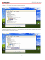
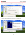
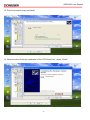
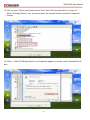
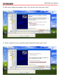
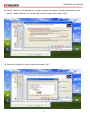
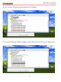
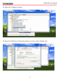
1
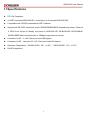
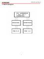
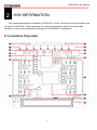
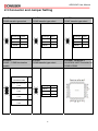
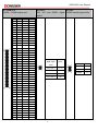
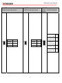
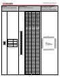
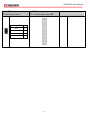
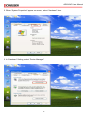
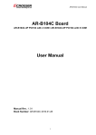
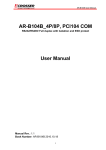
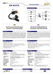
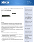
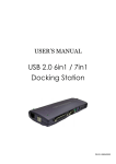
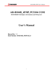
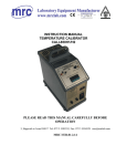
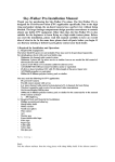
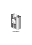
AR-B104C User Manual AR-B104C Board AR-B104C-4P PCI104 with 4 COM / AR-B104C-8P PCI104 with 8 COM User Manual Manual Rev.: Book Number: AR-B104C 2009.12.17 1 AR-B104C User Manual Revision Version Date Author 1.0 2009/12/17 Ken Description Release 2 AR-B104C User Manual Copyright 2009 All Rights Reserved. Manual’s first edition: For the purpose of improving reliability, design and function, the information in this document is subject to change without prior notice and does not represent a commitment on the part of the manufacturer. In no event will the manufacturer be liable for direct, indirect, special, incidental, or consequential damages arising out of the use or inability to use the product or documentation, even if advised of the possibility of such damages. This document contains proprietary information protected by copyright. All rights are reserved. No part of this Manual may be reproduced by any mechanical, electronic, or other means in any form without prior written permission of the manufacturer. Trademarks AR-B104C is a registered trademarks of Acrosser; IBM PC is a registered trademark of the International Business Machines Corporation; Pentium is a registered trademark of Intel Technologies Inc; Award is a registered trademark of Award Software International Inc; other product names mentioned herein are used for identification purposes only and may be trademarks and/or registered trademarks of their respective companies. 3 AR-B104C User Manual Contents 1 INTRODUCTION .......................................................................5 1.1 SPECIFICATIONS ................................................................................. 6 1.2 PACKAGE CONTENTS .......................................................................... 7 1.3 BLOCK DIAGRAM ................................................................................ 8 2 H/W INFORMATION..................................................................9 2.1 LOCATIONS (TOP SIDE) ....................................................................... 9 2.2 CONNECTORS AND JUMPER SETTING ................................................ 11 2.3 CONNECTOR AND JUMPER SETTING .................................................. 12 OXUPCI954 DRIVE INSTALLATION GUIDE.............................17 4 AR-B104C User Manual 1 INTRODUCTION The Acrosser AR-B104C presents you the most reliable and cost effective UART solution, which provides RS-232/422/485 connection abilities to your system to control related industrial devices. Via PCI-104 interface, the AR-B104C can be connected more robust and transmit more effecient than PC-104. It also contain jumper for the customer to switch between RS-232/422/485 without any software setting. 5 AR-B104C User Manual 1.1Specifications PCI 104 Compliant. 4 UART channels(AR-B104C/4P), could option to 8 channel(AR-B104C/8P). Compatible with 16C550 performance UART channel. Supports all RS-232C transceiver mode. RS232/RS485/RS422 selectable by jumper. Reserve 2 GPIO from Oxford to identify the board is AR-B104C/4P, AR-B104C/8P, AR-B104B/4P, AR-B104B/8P Maximum baud rate to 15Mbps in asynchronous mode. Connector for 4P:2 x 22 2.0mm pin head 180 degree. Connector for 8P:two sets of 2 x 22 2.0mm pin head 180 degree. Operation Temperature:AR-B104C/4P: -20℃ to 85℃;AR-B104C/8P: -20℃ to 70℃. RoHS Compliance. 6 AR-B104C User Manual 1.2 Package Contents Check if the following items are included in the package. Quick Manual. AR-B104C-4P/AR-B104C-8P. 1 x Software Utility CD. 7 AR-B104C User Manual 1.3 Block Diagram 8 AR-B104C User Manual 2 H/W INFORMATION This chapter describes the installation of AR-B104C. At first, it shows the function diagram and the layout of AR-B104C. It then describes the unpacking information which you should read carefully, as well as the jumper/switch settings for the AR-B104C configuration 2.1 Locations (Top side) 9 AR-B104C User Manual JP4 COM4 transfer type select JP2 COM2 transfer type select JP9 COM1 ~ COM4 termination enable JP1 COM1 transfer type select COM 1~4 COM1 ~ COM4 output port UART Controller 2 OXuPCI954 for COM1 ~ COM4 JP12 PCI INT signal select CN1 PCI 104 slot signal from M/B JP6 COM6 transfer type select JP5 COM5 transfer type select JP7 COM7 transfer type select JP10 COM5 ~ COM8 termination enable JP8 COM8 transfer type select UART Controller 1 COM8 transfer type select COM 5~8 COM5 ~ COM8 output port JP11 PCI Clock and IDSEL signal select JP3 COM3 transfer type select 10 AR-B104C User Manual 2.2 Connectors and Jumper Setting 2.2.1 Locations (Top side) JP4 COM4 transfer type select JP2 COM2 transfer type select JP9 COM1 ~ COM4 termination enable JP1 COM1 transfer type select COM 1~4 COM1 ~ COM4 output port UART Controller 2 OXuPCI954 for COM1 ~ COM4 JP12 PCI INT signal select CN1 PCI 104 slot signal from M/B JP6 COM6 transfer type select JP5 COM5 transfer type select JP7 COM7 transfer type select JP10 COM5 ~ COM8 termination enable JP8 COM8 transfer type select UART Controller 1 COM8 transfer type select COM 5~8 COM5 ~ COM8 output port JP11 PCI Clock and IDSEL signal select JP3 COM3 transfer type select 11 AR-B104C User Manual 2.3 Connector and Jumper Setting 2.1 JP6 COM6 transfer type select 2.2 JP5 COM5 transfer type select 2.3 JP7 COM7 transfer type select Transfer type Select Transfer type Select Transfer type Select RS-232 3-4 RS-232 3-4 RS-232 3-4 RS-422 1 – 2, 5 - 6 RS-422 1 – 2, 5 - 6 RS-422 1 – 2, 5 - 6 RS-485 1-2 RS-485 1-2 RS-485 1-2 2.4 JP10 COM5 ~ COM8 termination enable 120R 2.5 JP8 COM8 transfer type select Select termination enable COM5 120R termination 1-2 enable COM6 120R termination 3-4 enable COM7 120R termination 5-6 Transfer type Select RS-232 3-4 RS-422 1 – 2, 5 - 6 RS-485 1-2 enable COM8 120R termination 7-8 enable 12 2.6 UART Controller 1 OX16C954 UART Controller for COM5~COM8 AR-B104C User Manual 2.7 COM 5~8 COM5 ~ COM8 output port 2.8 JP11 2.9 JP3 PCI INT and IDSEL signal COM3 transfer type select select Pin RS-232 RS-422 RS-485 1 DCD_8 N/C N/C 2 DSR_8 Rx-_8 Data-_8 3 RXD_8 Rx+_8 Data+_8 4 RTS_8 N/C N/C 5 TXD_8 N/C N/C 6 CTS_8 Tx-_8 N/C 7 DTR_8 N/C N/C 8 RI_8 Tx+_8 N/C 9 GND GND GND 10 +5V +5V +5V 11 DCD_7 N/C N/C 12 DSR_7 Rx-_7 Data-_7 13 RXD_7 Rx+_7 Data+_7 14 RTS_7 N/C N/C 15 TXD_7 N/C N/C 16 CTS_7 Tx-_7 N/C 17 DTR_7 N/C N/C 18 RI_3 Tx+_7 N/C PCI INT and 19 GND GND GND IDSEL signal 20 +5V +5V +5V 21 DCD_6 N/C N/C 22 DSR_6 Rx-_6 Data-_6 CLK0, IDSEL 0 1-2, 3-4 23 RXD_6 Rx+_6 Data+_6 CLK1, IDSEL 1 1-2 24 RTS_6 N/C N/C CLK2, IDSEL 2 3-4 25 TXD_6 N/C N/C 26 CTS_6 Tx-_6 N/C CLK2, IDSEL 3 N/A 27 DTR_6 N/C N/C 28 RI_6 Tx+_6 N/C 29 GND GND GND 30 +5V +5V +5V 31 N/C N/C N/C 32 N/C N/C N/C 33 DCD_5 N/C N/C 34 DSR_5 Rx-_5 Data-_5 35 RXD_5 Rx+_5 Data+_5 36 RTS_5 N/C N/C 37 TXD_5 N/C N/C 38 CTS_5 Tx-_5 N/C 39 DTR_5 N/C N/C 40 RI_5 Tx+_5 NC 41 GND GND GND 42 +5V +5V +5V 43 N/C N/C N/C 44 N/C N/C N/C Select Transfer type Select RS-232 3-4 RS-422 1 – 2, 5 - 6 RS-485 1-2 select 13 AR-B104C User Manual 2.10 JP4 COM4 transfer type select 2.11 JP2 COM2 transfer type select 2.12 JP9 COM1 ~ COM4 termination enable 120R Select Termination enable COM1 120R Transfer type Select Transfer type Select termination enable RS-232 3-4 RS-232 3-4 COM2 120R RS-422 1 – 2, 5 - 6 RS-422 1 – 2, 5 - 6 termination enable RS-485 1-2 RS-485 1-2 COM3 120R 1-2 3-4 5–6 termination enable COM4 120R termination enable 14 7-8 AR-B104C User Manual 2.13 JP1 COM1 transfer type select Transfer type 2.14 COM 1~4 COM1~ COM4 output port 2.15 UART Controller 2 OXuPCI954 UART Controller for COM1~COM4 Pin RS-232 RS-422 RS-485 1 DCD_4 N/C N/C 2 DSR_4 Rx-_4 Data-_4 3 RXD_4 Rx+_4 Data+_4 4 RTS_4 N/C N/C 5 TXD_4 N/C N/C 6 CTS_4 Tx-_4 N/C 7 DTR_4 N/C N/C 8 RI_4 Tx+_4 N/C 9 GND GND GND 10 +5V +5V +5V 11 DCD_3 N/C N/C 12 DSR_3 Rx-_3 Data-_3 13 RXD_3 Rx+_3 Data+_3 14 RTS_3 N/C N/C 15 TXD_3 N/C N/C 16 CTS_3 Tx-_3 N/C 17 DTR_3 N/C N/C 18 RI_3 Tx+_3 N/C 19 GND GND GND Select 20 +5V +5V +5V RS-232 3-4 21 DCD_2 N/C N/C RS-422 1 – 2, 5 - 6 22 DSR_2 Rx-_2 Data-_2 23 RXD_2 Rx+_2 Data+_2 RS-485 1-2 24 RTS_2 N/C N/C 25 TXD_2 N/C N/C 26 CTS_2 Tx-_2 N/C 27 DTR_2 N/C N/C 28 RI_2 Tx+_2 N/C 29 GND GND GND 30 +5V +5V +5V 31 N/C N/C N/C 32 N/C N/C N/C 33 DCD_1 N/C N/C 34 DSR_1 Rx-_1 Data-_1 35 RXD_1 Rx+_1 Data+_1 36 RTS_1 N/C N/C 37 TXD_1 N/C N/C 38 CTS_1 Tx-_1 N/C 39 DTR_1 N/C N/C 40 RI_1 Tx+_1 N/C 41 GND GND GND 42 +5V +5V +5V 43 N/C N/C N/C 44 N/C N/C N/C 15 AR-B104C User Manual 2.16 JP12 PCI INT signal select 2.17 CN1 PCI 104 slot signal from M/B PCI INT signal select Select INTA 1–2 INTB 3-4 INTC 5-6 INTD 7-8 16 AR-B104C User Manual OXuPCI954 Drive Installation Guide When you install the OXuPCI954 drivers in AR-B104C, the driver’s installation sequence must follow this guide. If the COM ports sequences define that you want to set as the same with hardware define. For AR-B104C/4P, you only need to install “PCI Serial Port” driver (step1 to step13). If you use AR-B104C/8P, you need to install “PCI Serial Port” driver (step1 to step13) and “Other PCI Bridge Device” driver (step14 to step22). If you want to adjust the COM port properties, you can follow step23 to step26 to adjust the COM port properties. Installation Step: 1. Click the right button of mouse on “My Computer” icon, the screen will show the function list then select the “Properties” function. 17 AR-B104C User Manual 2. When “System Properties” appear on screen, select “Hardware” item. 3. In “Hardware” Setting, select “Device Manager” 18 AR-B104C User Manual ? PCI Serial Port” device in system devices list. 4. Select “? ? PCI Serial Port” icon, then screen will shows the function 5. Click the right button of mouse on “? list then selects the “Properties” function. 19 AR-B104C User Manual ? PCI Serial Port” Properties appear on screen, select “Reinstall Driver” item. 6. When “? 7. After driver install screen appear, select “Yes, this time only” then select “Next”. 20 AR-B104C User Manual 8. Select “Install from a list or specific location (Advanced)” then select “Next”. 9. Select “Search for the best driver in these locations” then select “Include this location in the search”. Select “Browse” for the file path of driver location then select “Next”. 21 AR-B104C User Manual 10. Select the file path of driver location then select “OK”. 11. Select “Next” to install driver. 22 AR-B104C User Manual 12. Driver files start to copy and install. 13. When the driver finish the installation of the “PCI Serial Port”, select “Finish”. 23 AR-B104C User Manual ? 14. You can see 4 “Enhanced Communication Port” add. Click the right button of mouse on “? Other PCI Bridge Device” icon, the screen show the function list then select the “Properties” function. ? Other PCI Bridge Device” icon Properties appear on screen, select “Reinstall Driver” 15. When “? item. 24 AR-B104C User Manual 16. After driver install screen appear, select “Yes, this time only” then select “Next”. 17. Select “Install from a list or specific location (Advanced)” then select “Next”. 25 AR-B104C User Manual 18. Select “Search for the best driver in these locations” then select “Include this location in the search”. Select “Browse” for the file path of driver location then select “Next”. 19. Select the file path of driver location then select “OK”. 26 AR-B104C User Manual 20. Select “Next” to install driver. 21. Driver files start to copy and install. When the driver finish the installation of the “Other PCI Bridge Device”, select “Finish”. 27 AR-B104C User Manual 22. You can see 4 “Enhanced Communication Port” be added. 23. If you want adjust the COM port setting, click the right button of mouse on the COM port icon. 28 AR-B104C User Manual 24. Select the “Properties” function. 25. When the COM Port icon Properties appear on screen, select “Settings” item. 29 AR-B104C User Manual 26. When the properties of the COM Port icon appear on screen, select the item which you want to change, such as the sequence of the COM Port, if you setup the COM Port finish, select “OK”, the setting will be changed. 30