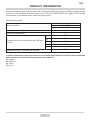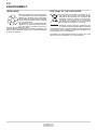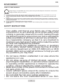
1
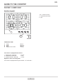
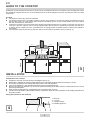
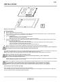
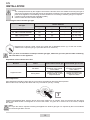
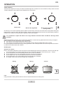
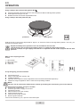
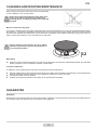
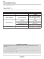
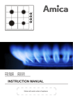
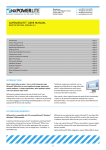
PHCZ6511 / KMG13169C / PHCG4.1ZpZtC INSTRUCTION MANUAL EN DEAR CUSTOMER, Outstanding user-friendliness and excellent efficiency make cooktops a perfect choice. Please read this manual thoroughly before you start to use the appliance to avoid any trouble. The cooktop’s safety and functionality was checked at the factory test stations prior to dispatch. Please read this manual carefully before you start to use this cooktop. This way, you can ensure its proper and correct operation. Please preserve this manual and store it near the appliance, so that it is available at all times for reference. Observe the instructions contained herein to prevent accidents. Note Do not start to use the appliance before you have read and understood the instructions. This equipment has been designed solely as a cooking appliance. It is strictly prohibited to use it for any other purpose, e.g. heating. Using the appliance for other purposes can be dangerous. The manufacturer reserves the right to introduce modifications which will not affect the functionalities and operation of the appliance. TABLE OF CONTENTS ENVIRONMENT3 SAFETY INSTRUCTIONS4 GUIDE TO THE COOKTOP 6 INSTALLATION8 ADJUSTMENT OF THE REDUCED VALVE FLOW 10 OPERATION11 CLEANING AND ROUTINE MAINTENANCE 13 GUARANTEE13 TROUBLESHOOTING14 2 EN PRODUCT INFORMATION Product information given in accordance with Commission Regulation (EU) No 66/2014 supplementing Directive of the European Parliament and Council Directive 2009/125/EC with regard to eco‑design requirements for household ovens, hobs and range hoods Household gas hobs PHCZ6511 / KMG13169C PHCG4.1ZpZtC 1106076 Model identifier O/V/O Hob type (electric / gas / gas‑electric) 4 Number of gas burners Energy efficiency for each gas burner (EE gas burner) FL 53,5 RL 53,5 RR 53,5 FR 53,5 C 53,5 Energy efficiency of gas hob (EE gas hob) In order to determine compliance with the eco‑ design requirements, the measurement methods and calculations of the following standards were applied: EN 60350‑1 EN 60350‑2 EN 15181 EN 30‑2‑1 3 EN ENVIRONMENT UNPACKING DISPOSAL OF THE APPLIANCE Old appliances should not simply be disposed of with normal household waste, but should be delivered to a collection and recycling centre for electric and electronic equipment. A symbol shown on the product, the instruction manual or the packaging shows that it is suitable for recycling. During transportation, protective packaging was used to protect the appliance against any damage. After unpacking, please dispose of all elements of packaging in a way that will not cause damage to the environment. All materials used for packaging the appliance are environmentally friendly; they are 100% recyclable and are marked with the appropriate symbol. Caution! During unpacking, the packaging materials (polythene bags, polystyrene pieces, etc.) should be kept out of reach of children. Materials used inside the appliance are recyclable and are labelled with information concerning this. By recycling materials or other parts from used devices you are making a significant contribution to the protection of our environment. Information on appropriate disposal centres for used devices can be provided by your local authority. 4 EN ENVIRONMENT HOW TO SAVE ENERGY Using energy in a responsible way not only saves money but also helps the environment. So let’s save energy! And this is how you can do it: ■ ■ ■ ■ ■ Use appropriate cookware: flat and thick bottom pots and pans will reduce power consumption by up to one third. Do not forget to use lid to reduce power consumption by four times! Select properly sized cookware: make sure the diameter of the pan or pot is not smaller than the size of the burner. Keep the burner surfaces and the cookware bottoms clean: Residues hinder heat transfer, and lasting contamination can be removed only by extremely harmful chemicals. Particularly, the flame slots of the burners must be kept clean at all times. Do not put up the cookware lids unless really necessary. Do not install the cooktop adjacently to fridges / freezers: this increases power consumption of the cooling appliances. SAFETY INSTRUCTIONS Your safety and that of your family are of the utmost importance to us and although some simple safety when cooking is generally observed it is worth reading through the following points to ensure that your hob is operated as safely as possible at all times to prevent any accidents. As a responsible company we feel it is very important to maintain a very high level of safety and to make this section as clear and highlighted as possible. Should you have any additional concerns or questions on any safety related matters please feel free to contact our service department on 0844 815 8880 (UK) or 0818 464646 (ROI) and our staff will endevour to help you with any questions you may have. • Do not leave children unattended in an area where the appliance is in use. • Do not allow persons of limited physical, sensual, or psychological capabilities, or persons whose experience in operating similar appliances is limited to operate the cooktop, unless if attended by (adult) caretakers. • Make sure no part of the power cord comes in contact with hot parts of the hob. • Leave sufficient space around the socket to ensure the power plug is accessible easily after installation. • Do not install the hob near cooling appliances. • Do not leave the hob unattended while in use. Boil5 EN SAFETY INSTRUCTIONS overs cause smoking, and greasy spill-overs may ignite presenting a fire risk. • Execute caution when the food is boiling. Boil-overs may flood the burner. • Should a malfunction occur, stop using the appliance. Do not start to use your hob before a Gas Safe engineer has repaired it. • Make sure all the burners are closed before opening the main gas valve at the network or container connection. • Do not place cooking pans directly onto the burners. • Maximum weight of a pan to be placed over a single burner is 5 kg. The overall maximum load of a pan that is to be placed over the entire grate is 10 kg. Do not place a single pan over two burners at the same time. • Do not impact the burners and knobs. • It is prohibited to modify or repair the hob by persons who do not possess appropriate training and qualifications. • Do not set the burner knobs open before you have stricken the match or the ignition appliance. • Do not extinguish the flame by blowing. • The user is not allowed to convert the hob to another gas type, relocate the appliance, or modify the supply network himself. Only a duly authorised and Gas Safe is allowed to carry out these activities. • Do not connect antenna cords (e.g. radio antennae) to the gas pipes. 6 EN GUIDE TO THE COOKTOP PHCZ6511 / KMG13169C PHCG4.1ZpZtC 2 2 1,2,3 - surface burners 4 - surface burner knobs 5 - grid 1 3 5 5 4 1 TECHNICAL DATA l l l l heigh depth width weight of the cooker 98 mm 520 mm 600 mm 12,5 kg The cooker is equipped with burners: 1 - WOK burner, heat load 2 - small burner, heat load 3 - medium burners, heat load - 2,8 kW - 1 kW - 1,8 kW Appliance class: see rating plate The cooker is equipped with a pipe terminal - 1/2” ISO 228-1 7 EN GUIDE TO THE COOKTOP Installation work and repairs should only be performed by a qualified technician in accordance with all applicable codes and standards. Repairs and service by unqualified persons could be dangerous and the manufacturer will not be held responsible. Location l The kitchen must be dry and well ventilated. l The kitchen should have a ventilation system including fume exhaust to remove the gases generated by burning gas and direct them out. That system shall comprise a ventilation grill or a hood. Please install hods in accordance with the manufacturers’ instructions. l Fresh air is necessary to ensure gas burning. Minimum gas requirement for the cooktop is 2 cbm per hour per each 1 kW of the burners’ capacity. The air can be supplied either directly from the outside by an at least 100 cm2 duct, or directly from the adjacent rooms, provided these are equipped with ventilation system routed to the outside of the building. l The minimum distance between the burners and the hood exhaust should be 750 mm (see fig. 3). 750mm 350mm 50mm 250mm 250mm 350mm 50mm 850mm Min 300 3 INSTALLATION Installation of the cooktop: l Prepare the work top cut-out as shown in the diagram (see fig. 5). l Remember to maintain the minimum safety distances to combustible surfaces below the cooktop of 130 mm. l Fix the tape (included) to the cooktop edge at the bottom side of the appliance. l Connect the appliance to gas and electrical mains as per the operating manual. l Remove any dust from the work top, remove the protective backing of the tape, insert the cooktop into the cut-out, and press firmly downwards. l Set the fixing brackets (see fig. 4) perpendicular to the cooktop edge, fix firmly. l Test the correct operation of the installed cooktop. In particular, check the correct operation of the sealing protection and the ignition system. Fixing the brackets to the work top 1. Work top 2. 4 screws 3. 4 fixing brackets 4. Installed appliance 4 8 EN INSTALLATION 5 Notes for the technician Instalator powinien: l The fitter should: l Bear a valid certificate of gas permit l Have studied the contents of the appliance’s type plate containing the suitable type of gas. Compare the data with the characteristics of the gas available in the network. l Check the following: • ventilation capacity, incl. air exchange in the kitchen, • tightness and sealing of the gas fittings, • effectiveness and correct operation of all the functional elements. l Adjust the settings of the gas control knobs with the washers included to ensure the igniters work properly and the entire system is leak-proof; • check the operation of the igniters and leak seal, • remove the knob if working incorrectly, and adjust bi introducing washer(s) onto the valve spindle, • check the operation of the igniters and leak seal, • secure the system with a tight washer and put the knob handle on. l Issue a certificate of connecting the appliance and inform the user of the operating activities. NOTE! Installation and service must be performed by a qualified and licensed installer, service agency or gas supplier. All the relevant safety regulations must be observed. The cooktop is equipped with an R1/2” connecting pipe for gas connection. If the appliance is intended for use with LPG (propane – butane), a Ø 8 x 1 mm hose coupling is threaded onto the connector. Make sure the gas connecting pipe does not come in contact with the metal components of the cooktop. All the couplings and joints must be tightly sealed. Note. After connecting the appliance check all fittings for gas leaks e.g. with soapy water. Do not check the fittings with open fire! Please make sure you have read and understood the entire operating manual. Do follow the instructions to ensure safe and effective operation of your cooktop. NOTE: The appliance uses gas, which is a flammable and explosive substance. Thus, it is necessary for the cooktop to be connected to a gas network which supplies the gas type for which the appliance is suitable. Installation and service must be performed by a qualified installer, service agency or gas supplier. Please check the type plate for the information concerning the suitable gas type for your appliance. Converting the unit to another gas type Only a licensed and authorised technician may carry out this job. If the available gas type is different from that provided in the type plate of the appliance (G 20 (GZ 50) 20 mbar, the burner nozzles should be replaced and flame adjusted. 9 EN INSTALLATION NOTE The cooktops delivered by the supplier come with the burners which are suitable for burning the type of gas which is quoted in the type plate and in the guarantee certificate. The type plate is fitted at the bottom panel of the appliance. The following must be carried out if converting to another gas type is required: l nozzles must be replaced (see assembling table), l reduced valve flow rate must be adjusted. Converting the unit to another gas type Nozzle diameter Gas type Small Medium Large WOK 2H G20/20mbar 72 92 - 55 + 2 x 75 3+, 3B/P G30/28÷30mbar 52 67 - 37 +2 x 55 3B/P G30/37mbar 46 62 - 37 x 2 x 52 3B/P G30/50mbar 45 52 - 26 + 2 x 45 Replacement of burner nozzle: loosen the nozzle with a dedicated wrench (7). Fit the new nozzle, suitable for the required gas type (see table above for reference). After you have converted the cooktop to another gas type, make sure you have placed a label containing that information on the appliance. Adjustment of the reduced valve flow Burners Regular burners Flame Converting the cooktop from LPG to natural gas Converting the cooktop from natural gas to LPG Full flame Replace the burner nozzle according to the guidelines in table 1 Replace the burner nozzle according to the guidelines in table 1 Saving flame Loosen the adjustment spindle (see fig. 7) and adjust the flame Loosen the adjustment spindle (see fig. 7) and adjust the flame Valve adjustment Valve adjustment should be done with the control knob set at Burner ON saving flame position. Remove the knob, and adjust the flame with a tiny screwdriver (see fig. 7 below). 7 Checking the adjusted flame: heat the burner at full open position for 10 minutes. Then turn the knob into the saving setting. The flame should not extinguish nor move to the nozzle. If it goes off or moves over to the nozzle, readjust the valves. Note. It is up to the used to request converting the appliance to another gas type if so required by the local conditions at a licensed gas fitter / service. 10 EN OPERATION Flame selection At the burners adjusted correctly, the flames should be light blue, and the inner cone should be clearly visible. The size of flame depends on the position of the related burner control knob. Burner OFF Burner ON, large flame 8 - Burner ON, small flame (saving mode) See also fig. 8 for various operating options (flame size selection); the burner should be set at a large flame during the initial phase of cooking to bring the food to boiling, and then the knob should be turned to the saving flame position to maintain the cooking. It is also possible to adjust the flame size stepless. It is prohibited to adjust the flame in the range between the Burner OFF and Burner ON large flame positions. Significant quantities of energy can be saved if the appliance is used correctly, parameters set correctly, and appropriate cookware is used. The savings can be as follows: l Up to 60 per cent savings when proper pots are used, l Up to 60 per cent savings when the unit is operated correctly and the suitable flame size is chosen. It is a prerequisite for efficient and energy-saving operation of the cooktop that the burners are kept clean at all times (in particular the flame slots and nozzles). Suitable pans Selection of vessels Bear in mind that the diameter of the pot must be at least slightly larger than that of the flame. Cover the pots with lids. It is recommended to use pots the diameters of which exceed the diameters of the flame by 2.5 – 3 times; l For the small burner, the most suitable pot will be 90-140 mm in diameter, l For the medium burner, the most suitable pot will be 140-220 mm in diameter, l For the large burner, the most suitable pot will be 200-240 mm in diameter, l For the WOK burner, the most suitable pot will be 220-260 mm in diameter, l The height of the pot should not be larger than its diameter. Wrong Wrong Correct 9 Lids: Using a lid while cooking will minimize the loss of heat and decrease the cooking time. 11 EN OPERATION Using cooktops with control knob ignition (Zp) l Press the selected control knob and turn anti-clockwise into Burner ON large flame position. l Hold depressed until gas is on fire l Release the knob and set the required flame size. Using cooktops with leak protection (Zt) spark igniter protection 10 Hold the burner’s control knob depressed for approx. 10 seconds in Burner ON large flame position. This way, you activate the protection device. Repeat the attempt if the protection has not activated for the first time. Leak protection will cut off the gas supply if there is no flame for approx. 60 seconds. At the Zt cooktops, the gas supply to the burners is adjusted with the knobs equipped with the leak prtection. What to do if surplus gas leak occurs 1 – gas network 2 – gas cut off valve A – valve ON B – valve OFF 11 In any emergency, proceed as follows: l turn the burners off l set the cut off valve OFF (see fig. 9 B) l ventilate the kitchen l report the unit for repair at a service department of a licensed and authorised repair shop l refrain from using the appliance until it is returned to its operating condition NOTE The user can fix some minor malfunctions himself, by following the instructions given in this manual. The burner does not ignite, and gas is smelled; l Close burner control knobs l Close the gas mains / supply cut off valve l Ventilate the kitchen l Take the burner out of the cooktop l Clean and blow the slots l Insert the burner back in place l Resume ignition attempt. If the burner still fails to go on, report for a licensed repair. 12 CLEANING AND ROUTINE MAINTENANCE EN Daily cleaning and proper maintenance have crucial impact on the durability of your ceramic plate. Clean the ceramic plate observing the same rules as for glass. Never use abrasive or aggressive cleaning agents, scrubbing powders or scratching sponges. Burners, the burner hob grate. In the case of soiled burners and grate, these elements must be removed from the cooker and washed with warm water and washing – up products intended for fats and soils. Next, wipe them dry. After the grate has been removed, wash the burner hob carefully and wipe with a dry and soft cloth. In particular, ensure flame openings in rings under caps are clean, see the figure below. Do not use steel wire or drill holes. Burner elements must always be clean. Water particles may hamper gas flow and produce an incorrect burner flame. 12 Work panel l Clean the enamel coated work panel only with warm water with a mild solution of dishwashing liquid. Use mild dish washing liquids to remove otherwise resistant contamination. Periodic inspections In addition to current maintenance and care, the following shall be arranged for: l Periodic inspections of control elements and units of the cooktop. Upon expiration of the warranty, service department shall be ordered technical inspections of the appliance at least once every two years. l All operation faults must be repaired. l Cooktop units shall be maintained according to the maintenance schedule. GUARANTEE Guarantee Guarantee service will be granted as per the Guarantee Certificate. The manufacturer cannot be held responsible for any damage caused by improper use or operation of the appliance. 13 EN TROUBLESHOOTING In each case, proceed as follows: l Turn the burners off l Disconnect power supply l Report for repair l The user can fix some minor malfunctions himself, according to the guidance given in the tables below. Please check the information below before contacting the service department. PROBLEM CAUSE REMEDIES 1.The appliance does not work - power cut - check the home power fuse, replace if needed 2.Burner will not ignite - flame slots contaminated - close the gas cut off valve, close burner control knobs, ventilate the kitchen, take the burner out of the cooktop, blow and clean the flame slots - power cut - check the home power fuse, replace if needed 3.Igniter does not work 4.Burner extinguishes - gas supply break - open gas cut off valve - contaminated (caked) igniter - clean the igniter - control knob released too soon - hold the control knob depressed until the flame goes on and persists - control knob released too soon - hold the control knob depressed until the flame goes on and persists Manufacturer’s Declaration The manufacturer hereby declares that this product meets the requirements of the following European directives: l Low Voltage Directive 2006/95/EC, l Electromagnetic Compatibility (EMC) Directive 2004/108/EC l ErP Directive 2009/125/EC l Directive 2009/142/EC and has thus been marked with the symbol and been issued with a declaration of compliance made available to market regulators. 14 15 Amica Wronki S.A. ul.Mickiewicza 52 64-510 Wronki tel. 67 25 46 100 fax 67 25 40 320 www.amica.com.pl IO-TGC-0030/4 (04.2015)