1
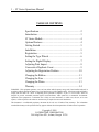
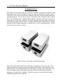
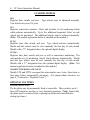
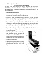
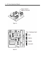
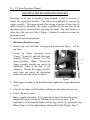
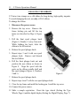
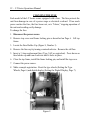
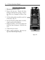
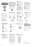
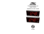
LT SERIES
User’s Manual
1 - LT Series Operations Manual
TABLE OF CONTENTS
Specifications ....................................................................... 2
Introduction.......................................................................... 3
LT Series Models ................................................................. 4
Optional Features ................................................................. 4
Getting Started ..................................................................... 5
Installation ........................................................................... 5
Registration .......................................................................... 5
Setting the Type Wheels ...................................................... 6
Setting the Digital Display................................................... 7
Adjusting Print Impact ......................................................... 8
Consecutive/Duplicate Count .............................................. 9
Adjusting the Registration Position ................................... 10
Changing the Ribbon ......................................................... 11
Changing the Fuse ............................................................. 12
Changing the Platen ........................................................... 13
Warranty ............................................................................ 14
WARNING: This equipment generates, uses, and can radiate radio frequency energy and, if not installed and used in
accordance with the instruction manual, may cause interference to radio communications. It has been tested and found to
comply with the limits for a Class A computing devise pursuant to Subpart J of part 15 of FCC Rules, which are
designed to provide reasonable protection against such interference when operated in a commercial environment.
Operation of the equipment in a residential area is likely to cause interference, in which case, the user, at his own
expense, will be required to take whatever measures may be required to correct the interference.
This document is a confidential proprietary document for the sole use of Lathem Time customers. The information
contained herein may not be reproduced for any purpose without the written permission of Lathem Time Corporation.
Copyright © 2009
LATHEM TIME CORPORATION
200 Selig Drive SW., Atlanta, Georgia 30336
2 - LT Series Operations Manual
SPECIFICATIONS
PHYSICAL
Height:
Width:
Depth:
Weight:
Case:
Color:
Power Cord Length:
COMPONENTS
Print Wheels:
Printing Platen Assembly:
Ribbon:
Fuse:
Digital Display:
Timing Motor:
Ribbon Drive Motor:
Transformer:
Numbering Solenoid:
Print Solenoid:
FEATURES
Print Impact Adjustment:
Time Format:
POWER REQUIREMENTS
Voltage:
Current:
Frequency:
7 inches
5 1/4 inches
11 inches
12 3/4 pounds (standard models)
14 pounds (numbering models)
Impact Resistant Reinforced Lexan
Cool Gray
6 Feet
Engraved Brass or Cast Zinc Alloy
Textured, soft surface for single copies.
Purple Silk
3 Amp.
LED
1 RPM, K342 type
21 RPM, Model 60-3
12 VAC, 50/60 Hz 117 VAC
(50/60 Hz 230 VAC Optional)
110/120 VAC (220 VAC Optional)
110/120 VAC (220 VAC Optional)
Variable, for multi-part forms
12-hour AM/PM
24-hour Continental Optional
110/120 VAC (220 VAC Optional)
9 Amp. Max. Intrm. 110/120 VAC
4 1/2 Amp. Max. Intrm. 220 VAC
60 Hz (50 Hz Optional)
POSSIBLE SHOCK HAZARD EXISTS WHEN CASE COVER IS REMOVED AND
AC POWER IS CONNECTED. USE CAUTION WHEN SETTING TYPE SECTION.
3 - LT Series Operations Manual
INTRODUCTION
The Lathem LT Series time stamps are considered "standard" by thousands of businesses and
institutions because of their low initial cost and years of proven, trouble-free operation. The LT
Series offers a wide variety of registration combinations that may be used for timing, numbering,
and dating functions. The LT Series consists of four models, and is designed to meet virtually
all of your validating needs. Standard features include: automatic registration; motor-driven
ribbon shift for smooth, quiet operation; easy ribbon changing; registration position adjustment;
and registration impact pressure control. Available options include a digital display, a manual
registration button; allowing automatic or manual action, as well as repeat numbering. All units
carry a full one-year factory warranty.
Lathem LT Series: Time, Date, and Numbering Stamps
Please read all directions carefully before operating or maintaining your LT Series unit. This
operations manual is designed to provide basic operating instructions. Minor maintenance and
adjustments may also be performed easily and effectively by referring to these instructions. For
service beyond the scope of this manual, contact the dealer from whom you purchased the
equipment, or Lathem Time Corporation. Should it be necessary to return the unit, retain the
original packing materials for shipping.
4 - LT Series Operations Manual
LT SERIES MODELS
LTD
Registers date, month, and year. Type wheels must be advanced manually.
Year wheels carry ten (10) years.
LTN
Registers consecutive numbers. Basic unit includes six (6) numbering wheels
which advance automatically. Up to five additional numerical, letter, or code
wheels may be purchased. The additional wheels must be advanced manually.
(Note: The manual registration button is standard on this module.)
LTT(C)
Registers time, date, month, and year. Type wheels advance automatically.
Month and date wheels must be reset manually the first day of each month.
Models with a "C" designation have the optional digital display.
LTTN(C)
Registers time, date, month, and year, as well as consecutive numbering. The
unit includes six (6) numbering wheels which advance automatically. Month
and date type wheels must be reset manually the first day of each month.
Models with a "C" designation have the optional digital display. (Note: The
manual registration button is standard on this module.)
CONSECUTIVE/DUPLICATE COUNT
Models LTN and LTTN can repeat the same number once, twice, three times or
four times before automatically advancing. (For jumper/shunt selection, see
page 8, "Consecutive / Duplicate Count.")
OPTIONAL FEATURES
INSCRIPTION PLATES
The die plates may be permanently fixed or removable. They can have up to 3
lines of 20 characters per line, or carry facsimile signatures. (Note: Removable
die plates must be removed before opening top frame and reinstalled after
closing top frame.)
5 - LT Series Operations Manual
24-HOUR FORMAT
The digital display models (LTTC and LTTNC) can display 12-hour (standard),
or 24-hour, also known as the Continental (0-23 hour), format, when specified at
time of order. The time wheels can print 24-hour format for an added charge.
FIXED PAPER GUIDE
Provides a fixed edge on the side of the time stamp to help the user make more
accurate registrations.
ADJUSTABLE PAPER GUIDE
Enables the user to position registrations more accurately on various paper sizes.
Adjustments are made quickly and easily with the slide mechanism.
MANUAL REGISTRATION BUTTON [Standard on LTN and LTTN(C)]
Enables the user to position the document and manually activate the imprint.
GETTING STARTED
Getting started with the LT Series is easy. There are only a couple of
fundamental decisions that must be made.
1. Plug the unit into the wall outlet.
2. Place the clock on top of the anti-skid rubber pad
3. Set the type section.
4. Set the digital clock (optional feature).
INSTALLATION
The LT Series time stamp installs easily on any tabletop or flat surface.
Determine whether you have a 110/120 VAC or 220 VAC unit, then plug it into
any appropriate AC wall outlet. (Note: Avoid outlets with On/Off switches.
These outlets may be accidentally turned off, causing an interruption of the
timing action.)
REGISTRATION
When forms are fully inserted into the stamp, an automatic
trigger causes registration. If the optional manual
registration button is installed, insert a form to the desired
position by aligning the desired registration position with
the print locators (Figure 1, Number 1) on the side of the
case. When the form is aligned, press the manual
registration button on the front of the unit (Figure 1,
Number 2).
Figure 1
6 - LT Series Operations Manual
SETTING THE TYPE WHEELS
As noted in the earlier sections LT SERIES MODELS and OPTIONAL
FEATURES, the LT Series Models are available with a variety of date, time,
and number wheels. You may set the applicable type wheels according to the
following directions.
1. Disconnect the power source.
2. Remove the top cover by inserting the key in the back of the unit, turning the
key clockwise, and pulling the cover up and forward.
3. Remove the frame locking pin (Figure 2, Number 1). Lift the top frame
(Figure 2, Number 2) to access time and date type wheels (Figure 2, Number
3) and number type wheels, if applicable.
4. Depress the time type setting lever (Figure 2, Number 4). Using a small
screwdriver or similar tool, rotate each individual date and time type wheel
down to the correct date and time. (Note: Month and date type wheels must
be reset manually the first day of each month.)
5. Depress the number type setting lever (Figure 2, Number 5) and rotate the
number type wheels (Figure 2, Number 6)
to the correct position.
6. Close the top frame and insert the locking
pin, positioning the pull ring down and
inside the case. Reinstall the top cover,
fitting the top securely into the grooves in
the main frame case. Lock the top in place.
7. Connect the power source.
8. Make a registration to check for accurate
date, time, and number readings.
If
necessary, reset the digital display. (See
Page 7.)
Figure 2
7 - LT Series Operations Manual
SETTING THE DIGITAL DISPLAY
Models with a "C" affixed to their designation (LTTC and LTTNC) denote units
featuring a digital display. This display is factory-set for use in the 12-hour
AM/PM format or the 24-hour (Continental) format. The digital display should
always be synchronized with the time type wheels. To set the digital display
and synchronize the display with the time type wheels, do the following:
1. Connect the power source.
2. Locate the three (3) push-buttons labeled
SEC, HRS and MIN on the bottom of
unit (Figure 3).
Figure 3
3. Return the unit to its upright position with the digital display facing towards
you. Pull the unit forward slightly so the front hangs over the edge of the
table, thereby giving you access to the buttons. (Remember: The minute
button is on the right.)
4. Make a registration to see what time is indicated by the time stamp. Use the
HRS (center) and MIN (right) buttons to set the time to the hour and minute
indicated on the registration.
5. Place your finger on the minute button (right) but do not press it just yet.
Listen for the type section to advance; you will hear an audible click. When
you hear the click, immediately press the minute button to advance one
minute. Seconds are now synchronized with the type section.
6. Make another registration to check the imprint feature for accuracy.
(Note: Interruptions in power lasting more than 3 to 5 seconds will cause the
digital display to flash, indicating that it is necessary to reset the display.)
8 - LT Series Operations Manual
ADJUSTING PRINT IMPACT
Print impact may be set to any desired level,
from very hard to very light. The impact
adjuster is located on the bottom of the unit.
Using a small flat head screwdriver, turn the
adjuster to the right to increase or left to
decrease the impact. (Figure 4)
(Note: To extend the effective life-span of
the unit, use the lightest adjustment possible,
which still gives a legible imprint.)
Figure 4
CONSECUTIVE/DUPLICATE COUNT (Numbering Units)
Units equipped with the numbering feature may be configured for Consecutive
Count, advancing the number type wheel after each registration, Duplicate
Count, advancing the number type wheel after every two registrations.,
Triplicate Count, advancing the number type wheel after every three
registrations, or Quad Count, advancing the number type wheel after every four
registrations. All units are shipped with the Consecutive Count mode enabled.
Units having circuit board version “E” and above also support Triplicate and
Quad numbering options. (See figure 6b).
To switch to Duplicate Count mode, disconnect the power. Locate and
remove the Access Cover (Figure 4) using a Phillips-head screwdriver. The
version of the Control Circuit installed is indicated on the product label, on the
underside of the unit, as well as on the circuit board, itself. On version “D”
circuit boards, the shunt is placed over 2 pins (Figure 6a). Remove the shunt
and place it over just 1 pin. To return to the Consecutive mode, reverse the
procedure. For units having circuit board version “E” and above, the DUP,
TRIP, and QUAD numbering features are selected by positioning the shunt
according to (Figure 6b).
9 - LT Series Operations Manual
10 - LT Series Operations Manual
ADJUSTING THE REGISTRATION POSITION
Depending on the type of document being stamped, it may be necessary to
change the registration position. This can be accomplished by moving the
trigger assembly. The trigger assembly has a range of motion of about two (2)
inches forward or backward. The trigger assembly tells the unit how far the
document must be inserted before activating the stamp. The print locators on
either side of the top cover (Page 5, Figure 1, Number 1) can help you center the
registration point.
To adjust the registration position:
1. Disconnect the power source.
2. Remove top cover and frame locking pin as described on Page 6. Lift the
top frame.
3. Loosen the trigger adjustment screw
(Figure 7, Number 1) and slide the trigger
assembly (Figure 7, Number 2) to the
desired position. (Note: Moving the
trigger assembly towards you places the
registration closer to the edge of the
document. Moving the trigger assembly
away from you places the registration
farther from the edge of the document.)
Figure 7
4. With trigger assembly in the desired position, tighten the trigger adjustment
screw.
5. Close the top frame, install the frame locking pin, and replace the top cover.
6. Connect the power source.
7. Make a sample registration. If the registration is not in the desired location,
readjust the trigger assembly by following the previous six steps. If the
registration is in the desired location, reset the type wheels (see Setting the Type
Wheels, Page 6) and the digital display (Setting the Digital Display, Page 7).
11 - LT Series Operations Manual
CHANGING THE RIBBON
LT Series time stamps use a silk ribbon for long-lasting, high-quality imprints.
To avoid damaging the unit, use only a #20-S ribbon.
To change the ribbon:
1. Disconnect the power source.
2. Remove the top cover. Remove the
frame locking pin and lift the top
frame (as described on Page 6, Figure
2).
3. Pull the front spool plunger knob
(Figure 8, Number 1) away from unit.
While holding the knob, slide the
ribbon to the left and out.
4. Release the spool plunger knob.
5. Repeat steps 3 and 4 with rear spool
plunger knob. Remove and discard
the used ribbon.
6. Pull the front plunger knob out and
position the new ribbon as shown in
Figure 8. Align the spool with the
posts on the ribbon spindle shaft and
the spool plunger (Figure 8, Numbers
2 and 1).
Figure 8
7. Release the spool plunger knob.
8. Repeat steps 6 and 7 with the rear spool plunger knob.
9. Close the top frame and install the locking pin. Install the top cover.
10. Connect the power source.
11. Make a sample registration. Reset the type wheels (Setting the Type
Wheels, Page 6) and the digital display (Setting the Digital Display, Page 7).
12 - LT Series Operations Manual
CHANGING THE FUSE
Each model of the LT Series comes equipped with a fuse. The fuse protects the
unit from damage in case of a power surge or electrical overload. If too much
power reaches the fuse, the fuse burns out, or is "blown," stopping operation of
the unit and avoiding costly damage.
To change the fuse:
1. Disconnect the power source.
2. Remove top cover and frame locking pin as described on Page 6. Lift top
frame.
3. Locate the Fuse Holder Cap (Figure 9, Number 1).
4. Remove the fuse cap by turning counterclockwise. Remove the old fuse.
5. Insert a 3 Amp replacement fuse (Type 3AG or equivalent). Press down on
fuse holder cap and turn clockwise until it locks in place.
6. Close the top frame, install the frame locking pin, and install the top cover.
7. Connect the power source.
8. Make a sample registration. Reset the type wheels (Setting the Type
Wheels, Page 6) and digital display (Setting the Digital Display, Page 7).
Figure 9
13 - LT Series Operations Manual
CHANGING THE PLATEN
1. Disconnect the power source.
2. Remove the top cover. Remove the frame
locking pin and lift the top frame. Remove
the ribbon (see Changing the Ribbon, Page
11).
3. Lift the printing platen assembly up and out
of the frame. (Fig. 10)
4. Insert the alternate printing platen assembly,
using the guide pin for alignment.
5. Replace the ribbon. Close the top frame and
install the frame locking pin. Install the top
cover.
6. Connect the power source.
7. Make a sample registration. Reset the time
type wheels and the digital display.
Figure 10
14 - LT Series Operations Manual
Limited One-Year Limited Warranty
Lathem warrants the hardware products described in this guide against defects in material and workmanship for
a period of one year from date of original purchase from Lathem or from an authorized Lathem reseller. The
conditions of this warranty and the extent of the responsibility of Lathem Time Corporation (“Lathem”) under
this warranty are listed below.
1.
This warranty will become void when service performed by anyone other than an approved Lathem
warranty service dealer results in damage to the product.
2.
This warranty does not apply to any product which has been subject to abuse, neglect, or accident,
or which has had the serial number altered or removed, or which has been connected, installed,
adjusted, or repaired other than in accordance with instructions furnished by Lathem.
3.
This warranty does not cover dealer labor cost for removing and reinstalling the machine for repair,
or any expendable parts that are readily replaced due to normal use.
4.
The sole responsibility of Lathem under this warranty shall be limited to repair of this product, or
replacement thereof, at the sole discretion of Lathem.
5.
If it becomes necessary to send the product or any defective part to Lathem or any authorized
service dealer, the product must be shipped in its original carton or equivalent, fully insured with
shipping charges prepaid. Lathem will not assume any responsibility for any loss or damage
incurred in shipping.
6.
WARRANTY DISCLAIMER AND LIMITATION OF LIABILITY: Except only the limited
express warranty set forth above, the products are sold with no expressed or implied warranties of
any kind, and the implied warranties of merchantability and fitness for a particular purpose are
hereby expressly disclaimed. No warranties are given with respect to products purchased other
than from Lathem or an authorized Lathem reseller and any such products are purchased "as is, with
all faults." In no event will Lathem be liable for any direct, indirect, special, incidental or
consequential damages arising out of or in connection with the delivery, use or inability to use, or
performance of this product. In the event any limited remedy given herein shall be deemed to have
failed of its essential purpose, Lathem's maximum liability shall be to refund the purchase price
upon return of the product.
7.
Proof of date of purchase from Lathem or an authorized Lathem reseller is required for warranty
service on this product.
8.
This Warranty grants specific legal rights. Additional legal rights, which may vary by locale, may
also apply.
9.
Should any difficulties arise with the performance of this product during warranty, or with any
Lathem authorized service centers, contact Lathem Time at the address below.
Lathem Time
200 Selig Drive, SW, Atlanta, GA 30336
404-691-0405
www.lathem.com
Copyright © 2009 Lathem Time Corporation. All rights reserved.
OMLTA1205