1
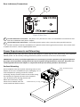
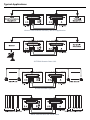
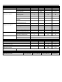
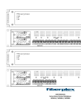
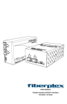
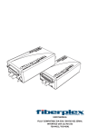
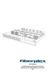
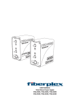
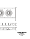
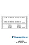
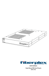
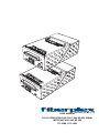
USER MANUAL FULLY COMPATIBLE EIA‐530 / 6X4 RS‐422 SERIAL INTERFACE with 1x2 RS‐232 TD‐1580 / TD‐1581 [This page intentionally left blank] Warning for Your Protection 1. Read these instructions. 2. Keep these instructions. 3. Heed all warnings. 4. Follow all instructions. 5. Do not use this apparatus near water. 6. Clean only with a dry cloth. 7. Do not block any of the ventilation openings. Install in accordance with the manufacturer’s instructions. 8. Do not install near any heat sources such as radiators, heat registers, stoves, or other apparatus (including amplifiers) that produce heat. 9. Do not defeat the safety purpose of the polarized or grounding‐type plug. A polarized plug has two blades with one wider than the other. A grounding type plug has two blades and a third grounding prong. The wide blade or the third prong is provided for your safety. If the provided plug does not fit into your outlet, consult an electrician for replacement of the obsolete outlet. 10. Protect the power cord from being walked on or pinched, particularly at plugs, convenience receptacles, and the point where they exit from the apparatus. 11. Only use attachments/accessories specified by the manufacturer. 12. Use only with the cart, stand, tripod, bracket, or table specified by the manufacturer, or sold with the apparatus. When a cart is used, use caution when moving the cart/apparatus combination to avoid injury from tip‐over. 13. Unplug this apparatus during lightning storms or when unused for long periods of time. 14. Refer all servicing to qualified service personnel. Servicing is required when the apparatus has been damaged in any way, such as power‐supply cord or plug is damaged, liquid has been spilled or objects have fallen into the apparatus, the apparatus has been exposed to rain or moisture, does not operate normally, or has been dropped. The apparatus shall not be exposed to dripping or splashing. No objects filled with liquids, such as vases, shall be placed on the apparatus. “WARNING: To reduce the risk of fire or electric shock, do not expose this apparatus to rain or moisture.” General Installation Instructions Please consider these general instructions in addition to any product‐specific instructions in the “Installation” chapter of this manual. Unpacking Check the equipment for any transport damage. If the unit is mechanically damaged, if liquids have been spilled or if objects have fallen into the unit, it must not be connected to the AC power outlet, or it must be immediately disconnected by unplugging the power cable. Repair must only be performed by trained personnel in accordance with the applicable regulations. Installation Site Install the unit in a place where the following conditions are met: The temperature and the relative humidity of the operating environment must be within the specified limits during operation of the unit. Values specified are applicable to the air inlets of the unit. Condensation may not be present during operation. If the unit is installed in a location subject to large variations of ambient temperature (e.g. in an OB‐van), appropriate precautions must be taken. Unobstructed airflow is essential for proper operation. Ventilation openings of the unit are a functional part of the design and must not be obstructed in any way during operation (e.g. ‐ by objects placed upon them, placement of the unit on a soft surface, or improper installation of the unit within a rack or piece of furniture). The unit must not be unduly exposed to external heat sources (direct sunlight, spot lights). Ambient Temperature Units and systems by FiberPlex are generally designed for an ambient temperature range (i.e. temperature of the incoming air) of +5...+40 °C. When rack mounting the units, the following facts must be considered: The permissible ambient temperature range for operation of the semiconductor components is 0 °C to +70 °C (commercial temperature range for operation). The airflow through the installation must allow exhaust air to remain cooler than 70 °C at all times. Average temperature increase of the cooling air shall be about 20 C°, allowing for an additional maximum 10 C° increase at the hottest components. If the cooling function of the installation must be monitored (e.g. for fan failure or illumination with spot lamps), the exhaust air temperature must be measured directly above the modules at several places within the enclosure. Grounding and Power Supply Grounding of units with mains supply (class I equipment) is performed via the protective earth (PE) conductor integrated in three‐pin Phoenix™ connector. Units with battery operation (< 60 V, class III equipment) must be earthed separately. Grounding the unit is one of the measures for protection against electrical shock hazard (dangerous body currents). Hazardous voltage may not only be caused by defective power supply insulation, but may also be introduced by the connected audio or control cables. This equipment may require the use of a different line cord, attachment plug, or both, depending on the available power source at installation. If the attachment plug needs to be changed, refer servicing to qualified personnel. Warranty, Service and Terms and Conditions of Sale For information about Warranty or Service information, please see our published ‘Terms and Conditions of Sale’. This document is available on fiberplex.com or can be obtained by requesting it from [email protected] or calling 301.604.0100. Disposal Disposal of Packing Materials The packing materials have been selected with environmental and disposal issues in mind. All packing material can be recycled. Recycling packing saves raw materials and reduces the volume of waste. If you need to dispose of the transport packing materials, recycling is encouraged. Disposal of Used Equipment Used equipment contains valuable raw materials as well as substances that must be disposed of professionally. Please dispose of used equipment via an authorized specialist dealer or via the public waste disposal system, ensuring any material that can be recycled has been. Please take care that your used equipment cannot be abused. After having disconnected your used equipment from the mains supply, make sure that the mains connector and the mains cable are made useless. Disclaimer The information in this document has been carefully checked and is believed to be accurate at the time of publication. However, no liability is assumed by FiberPlex for inaccuracies, errors, or omissions, nor for loss or damage resulting either directly or indirectly from use of the information contained herein. Introduction The TD‐1580 and TD‐1581 pair together to form a powerful balanced serial data transport solution. The DB‐25 connectors are pinned out to directly support an EIA‐530 serial link. However due to the transparency and flexibility of the design, the TD‐1580/81 can be used as 6x4 independent 6 Mbps RS‐422 channels and 2x1 independent 256 Kbps RS‐232 channels. This incredible versatility can solve a myriad of serial data communications problems. Your once limited serial links can not only be consolidated but extended to over 20 Km on a single fiber pair. SCADA (supervisory control and data acquisition), Telecommunications, Facility Automation and Control, even DMX Lighting control applications can all benefit from the TD‐1580/81. For more advanced systems, a ‘Regeneration’ switch on the TD‐1581 allows users to toggle between synchronous applications that require Send Timing (ST) and asynchronous or synchronous applications that require Terminal Timing (TT). Key Features Compatible with: o TIA/EIA‐530 (RS‐530) o MIL‐STD‐188‐114A balanced type 1 and type 2 o FED STD 1030A Can alternately be used for 6x4 RS‐422 and 1x2 RS‐232 EIA‐530 and RS‐422 channels support data rates from DC to 6.144 Mbps Can be used for up to 6 universes of DMX lighting control Includes power adapter as well as a 3‐position Phoenix™ Theory of Operation By using a technology unique to FiberPlex products called ‘transparency’, we are able to use all the clock, data and control channels of the standard EIA‐530 interface completely independently of one another. This provides the ability to have (4) bi‐directional RS‐422 serial with (2) unidirectional RS‐422 and (1) bi‐directional RS‐232 with (1) uni‐directional RS‐232, or even independently as (6) RS‐422 in one direction and (4) in the other [6x4] and (2) RS‐232 in one direction and (1) in the other [2x1]. The table later in the manual shows how these channels are pinned out. Differences between TD‐1580 and TD‐1581 The TD‐1580 has a female (sockets) DB‐25 connector and mates with the DTE. The TD‐1581 has a male (pins) DB‐25 connector, mates with the DCE and has clock regeneration functions. Getting Started Initial Inspection Immediately upon receipt, inspect the shipping container for damage. The container should be retained until the shipment has been checked for completeness and the equipment has been checked mechanically and electrically. If the shipment is incomplete, if there is mechanical damage, or if the unit fails to operate notify FiberPlex and make the shipping materials available for the carrier's inspection. Front Indicators/Connections Figure 1 TD‐1581 (left) and FOI‐1580 (right) Front Face 1 DCE & 3 DTE Connectors – Main data connections via D‐subminiature, 25‐position connector. The DCE is a male (pins) and the DTE is a female (sockets) connector. Jackscrews are provided for securement. See pinout below. PINOUTS Pin 1 7 2 14 3 16 4 19 5 13 20 23 6 22 24 11 8 10 15 12 17 9 18 25 21 TD‐1581 (DCE) Direction TD‐1580 (DTE) Direction 6x4 Serial Configuration Chassis Ground Signal Ground Out In In Out Out In In Out Out In In Out Out In In Out In Out Channel 5 RS‐422 In Out Channel 6 RS‐422 Out In Out In Out In Channel 1 RS‐422 Channel 2 RS‐422 Channel 3 RS‐422 Channel 4 RS‐422 Channel 1 RS‐232 Channel 2 RS‐232 TX+ TX‐ RX+ RX‐ TX+ TX‐ RX+ RX‐ TX+ TX‐ RX+ RX‐ TX+ TX‐ RX+ RX‐ RX+ RX‐ RX+ RX‐ TX RX TX EIA‐530 Configuration Chassis Ground Signal Ground Send Data A (SD) Send Data B (SD\) Receive Data A (RD) Receive Data B (RD\) Request To Send A (RTS) Request To Send B (RTS\) Clear To Send A (CTS) Clear To Send B (CTS\) Terminal Ready A (TR) Terminal Ready B (TR\) Data Set Ready A (DSR) Data Set Ready B (DSR\) Terminal Timing A (TT) Terminal Timing B (TT\) Receive Timing A (RT) Receive Timing B (RT\) Send Timing A (ST) Send Timing B (ST\) Receiver Ready A (RR) Receiver Ready B (RR\) Local Loopback (LL) Test Mode (TM) Remote Loopback (RL) 2 Regeneration Mode Switch – The REG1 and REG2 switch position is determined by the data rate of the RS‐422 link and the distance between the DCE and the DTE. In some cases, if the timing delays are just right, a link will function in 2 switch positions, NON and REG1, or NON and REG2. It is also possible for a link to operate in all 3 switch positions; NON, REG1, and REG2. However, in synchronous applications where the DCE provides Send Timing (ST), it would be more beneficial to use either REG1 or REG2 rather than NON because regeneration eliminates the sampling jitter from the Transmit Data (TD) to the DCE. See the table below. Label NON Position Description Typically set for asynchronous or synchronous applications requiring Terminal Timing (TT). Transmit Data (TD) and Terminal Timing (TT) from the DTE are both passed transparently to the DCE with the addition of normal propagation delay and sampling jitter. Up Regeneration Modes Typically set for synchronous applications requiring Send Timing (ST). This may be used to correct for timing delays over long runs of wiring between the DCE and the DTE. Terminal Timing from the DTE is ignored and will not be passed to the DCE. Instead, Send Timing (ST) from the DCE is looped back to the Terminal Timing (TT) output on the TD‐1580. REG1 Middle Transmit Data (TD) from the DTE is sampled in on the rising edge of Send Timing (ST) from the DCE. REG2 Down Transmit Data (TD) from the DTE is sampled in on the falling edge of Send Timing (ST) from the DCE. 5 SYN (sync) – LEDs indicating the status of signal presence or absence, and sync 4 SIG (signal) & character detection. See the table below. Label SIG SYN Color Description Green Optical signal in detected. Off No optical signal in or optical level too low. Check that the opposite unit has power and that the fiber optic cables are properly connected. The TX optic from one end of the network connects to the RX optic at the opposite end as shown under “TYPICAL APPLICATION”. Green Unit is in sync. Off No sync characters detected. Unit is unable to frame to the data stream. 6 SFP Port – Install an optical SFP in this slot. This slot conforms to the SFP MSA pinouts (INF‐8074i, more information later in this manual). Any standard MSA complaint optical SFP can be used in this slot that supports a minimum data rate of 346Mbps. Units ordered with the “‐L5B” and “‐L22” option come with an appropriate SFP pre‐installed. The “‐C” option has an empty SFP cage that can accept either a user supplied SFP or a Quadrax SFP‐SFP cable (ordered separately) for connection to the FiberPlex WDM16 or WDM8. 7 PWR – LED indicating presence of DC power in the unit. The LED can be interpreted according to the following table. Status Indicator Green Power supply in FOI unit is operating properly. Off No power from the PSQ power supply or open resettable fuse inside the FOI unit. Check that the PSQ power supply is operating properly. If the PSQ power supply is good, separate the FOI unit from the PSQ power supply for 30 seconds and then reattach so that the fuse inside the FOI unit has time to reset. If the PWR led is still off or not constant, replace the FOI unit. Rear Indicators/Connections Figure 2 Rear Face 8 Circular DC Power Connection – DC power entry for the unit. This is a standard DC connection for use with the included DC wall power adapter. 9 Phoenix DC Power Connection – Secondary power option. This is wired in direct parallel with the Circular connector and has the addition of a positive earth chassis ground connection. This can be used to power the unit on a client supplied power buss. Power Requirements and Mounting The TD‐1580 and TD‐1581 come with a 9V DC wall adapter for powering the units. Alternately, user supplied 7‐ 28 VDC power can be used by utilizing the Phoenix power connector on the rear of the module. IMPORTANT: For many serial data applications it is necessary to provide a positive earth ground reference for proper serial operation. Earth ground can only be supplied using the Phoenix connector. DC power can still be applied with the wall adapter in conjunction with just the earth ground on the Phoenix. Surface Mounting All TD modules have two keyhole mounting holes on the bottom of the unit. Included with your packaging is a 1:1 scale template for spacing screws for surface mounting. Simply transfer marks to the surface using the template as a guide and secure the supplied 1/2” #2 wood screws leaving about 1/16” below the head. Now, simply #2 Wood Screw, 1/2" Long, #1 Phillips lower the TD module over the Drive screw heads and slide to secure. Lower TD Unit Over Screw Heads, TDR‐01 Rear Connect Rack Complementing the flexibility of the FiberPlex ‘TD Series’ of fiber optic modules, the TDR‐01‐AC provides mounting, power and cable management for up to 6 modules in a compact and rugged aluminum 1U rack. With the TD modules rear facing, connections to the TD units are made from the rear, inside of the rack enclosure. The integrated key‐hole mounting holes on the bottom the TD units lock securely on mating studs while a rear retention bar holds them securely in place. A 6 position wiring harness and included power adapter provide, not just 9 VDC power, but a positive earth ground to the modules via 3 position Phoenix™ locking power connectors. Managing all that cabling and fiber can sometimes be quite a chore so an extended cabling tray with integrated tie down points are provided to help make your installation clean. TDP Front Connect Rack The TDP provides front of rack connection, mounting, power, and cable management for up to 6 front facing TD modules in a compact and rugged aluminum 1U rack. Each of the 16 channels of the modular TDP front panel can accommodate any Neutrik™ D Series connector, LC and ST barrel connectors, DB9 connectors, etc. The unused positions are simply fitted with a blank panel. The integrated key‐hole mounting holes on the bottom of the TD units lock securely on mating studs while a rear retention bar holds them securely in place. A 6 position power wiring harness and included power adapter provide, not just 9 VDC power, but a positive earth ground to the modules via 3 position Phoenix™ locking power connectors. Managing all that cabling and fiber can sometimes be quite a chore, the TDP allows a simple solution to put maximum capacity and flexibility into a single 1U space. TD‐DINR Din Rail Mounting The FiberPlex TD‐DINR is a specialized Mounting Bracket intended to mount a single FiberPlex TD‐Series unit onto DIN rail conforming to standard EN 50022 (top hat sections only). Either 35 x 7.5mm or 35 x 15mm section DIN rail will be compatible with this device. Possible mounting configurations are: Flat mounting, the lower profile but wider rail signature Or Edge mounting, the higher profile but narrower rail signature Inserting and Removing SFP Modules Handling Warnings SFP Modules are static sensitive. To prevent damage from electrostatic discharge (ESD), it is recommended to attach an ESD preventative wrist strap to your wrist and to a bare metal surface when you install or remove an SFP Module. Disconnect all optical or copper cables from SFP Modules prior to installing or removing the SFP Module. Failure to do so could result in damage to the cable, cable connector or the SFP Module itself. Removing and inserting an SFP Module can shorten its useful life, so you should not remove and insert SFP Modules any more often than is absolutely necessary. Protect optical SFP modules by inserting clean dust covers into them after the cables are removed. Be sure to clean the optic surfaces of the fiber cables before you plug them back into the optical ports of another SFP module. Avoid getting dust and other contaminants into the optical ports of your SFP modules, because the optics will not work correctly when obstructed with dust. Identify the Latch Type of the SFP Module SFP Modules have various latching mechanisms to secure them into the SFP Cage of a device. The FiberPlex WDM can support a host of manufacturers and brands of SFP Modules so the user may encounter any number of different latches. Some of these are described below. Bail Clasp Actuator Button The bail clasp SFP module has a clasp that you use to remove or install the SFP module. The actuator button SFP module includes a button that you push in order to remove the SFP module from a port. This button can either lift ‘Up’ or press ‘In’ to release the SFP Module depending on the manufacturer. Mylar Tab Slide Tab The Mylar tab SFP module has a tab that you pull to remove the module from a port. The slide tab SFP module has a tab underneath the front of the SFP module that you use to disengage the module from a port. Inserting a Module 1) 2) 3) 4) Attach an ESD‐preventative wrist or ankle strap, following its instructions for use. Disconnect and remove all interface cables from SFP Module. If the SFP Module has a Bail Clasp , close the Bail Clasp before inserting the SFP Module. With the gold finger connector on the bottom and the label on the top, line up the SFP Module with the empty cage and slide it in making sure that it is completely inserted and seated in the cage. Removing a Module 1) 2) 3) Attach an ESD‐preventative wrist or ankle strap, following its instructions for use. Disconnect and remove all interface cables from SFP Module. Release the latching mechanism. Bail Clasp – Open the bail clasp on the SFP Module with your finger in a downward direction. Actuator Button – Gently press the actuator up (or in) while pulling the body of the SFP Module to release the SFP Module from the cage. Mylar Tab – Pull the tab gently in a straight outward motion until it Actuator Button disengages from the port. Make sure the tab is not twisted when pulling as it may become disconnected from the SFP Module. Slide Tab ‐ With your thumb, push the slide tab on the bottom front of the SFP module in the direction of the equipment to disengage the module from the line card port. If you pull on the SFP module without disengaging the tab, you can damage the SFP module. 4) Grasp the SFP Module between your thumb and index finger and carefully remove it from the port 5) Place the SFP Module on an antistatic mat, or immediately place it in a static shielding bag or container Other Considerations Application Flexibility The units support tail circuit and null modem functions for DCE to DCE or DTE to DTE communications. This requires two of the same TD unit. An alternate interface (V.35 or RS‐232) may be installed at the opposite end, allowing the user to create a link between two electrically incompatible interfaces without requiring a separate interface converter. For more information, please see the “Optical Compatibility” table. SFP MSA Compliance The SFP Multi Source Agreement (MSA) is an agreement that was drafted among competing manufacturers of SFP optical modules. The SFF Committee was formed to oversee the creation and maintenance of these agreements including the SFP MSA designated as INF‐8074i. This agreement describes a mutually agreed upon standard for the form and function of SFP modules. However, not all SFPs produced are MSA compliant. The MSA provides for a transceiver (TX/RX) pinout. Other industries such as broadcast had the need for dual TX and dual RX SFP for uni‐directional applications such as video. Naturally, a non‐MSA standard was introduced allocating pinout assignments for dual output and dual input I/O configurations. In addition, the some of the internal serial communication pins were reassigned. The TD‐1580/TD‐1581 will only accept MSA compliant SFP modules which support the specified data rate. Pinout Comparison Chart PIN 1 2 3 4 5 6 7 8 9 10 11 12 13 14 15 16 17 18 19 20 Transceiver (MSA) VEE TX_FAULT [VEE] TX_DIS MOD_DEF(2) ‐ SDA MOD_DEF(1) ‐ SCL MOD_DEF(0) – PRESENCE [VEE] Rate [NC] LOS VEE VEE VEE RD‐ RD+ VEE VCC VCC VEE TD+ TD‐ VEE Transceiver (Non‐MSA) VEE VEE NC VEE SCL SDA VEE RX1_LOS NC NC VEE Rx1‐ Rx1+ VEE VCC VCC VEE Tx1+ Tx1‐ Tx1_DIS Dual TX (Non‐MSA) VEE NC NC VEE SCL SDA VEE Tx2+ Tx2‐ Tx2_DIS VEE NC NC VEE VCC VCC VEE Tx1+ Tx1‐ Tx1_DIS Dual RX (Non‐MSA) VEE Rx2‐ Rx2+ VEE SCL SDA VEE NC NC NC VEE Rx1‐ Rx1+ VEE VCC VCC VEE NC NC NC Typical Applications Generic Full Protocol EIA‐530 / RS‐422 Application SATCOM Remote Data Link 6 Channel DMX Lighting Multi‐Channel Discrete Serial Data Specifications Dimensions ELECTRICAL SPECIFICATIONS Min Typ Max Power Requirement Voltage Range 7 9 32 V Supply Current ‐ 625 ‐ mA Balanced Differential Signals Unbalanced Single‐Ended Signals Data Rate DC ‐ 6.144 Mbps Sampling Jitter 0 ‐ 23 % Input Load ‐ 100 ‐ Ω Common‐Mode Input Voltage ‐ ‐ ±7 V Common‐Mode Output Voltage (100 Ω load) ‐ 1.8 3 V DC ‐ 120 kbps 0 ‐ 0.4 % kΩ Data Rate Sampling Jitter Input Load Input Voltage Range Output Voltage (5 kΩ load) Environmental Storage Temperature Operating Temperature Interface Connector Unit 3 5 7 ‐25 ‐ 25 V ‐ ±5 ‐ V ‐40 ‐ 85 °C 0 ‐ 50 °C Min Typ Max Unit ‐ 270 ‐ Mbps TD‐1581 DB‐25 Male TD‐1580 DB‐25 Female OPTICAL SPECIFICATIONS External SFP Interface Data Rate Recommended Jitter ‐ ‐ 40 Psec Operating Voltage ‐ 3.3 ‐ VDC Maximum Current ‐ ‐ 500 mA Optical Modules SFP MSA (SFF‐8431, SFF‐8432, SFF‐8433) compliant slot, data rate 266 – 1.25 Gbps PHYSICAL SPECIFICATIONS Case Dimensions TD‐1580 / TD‐1581 Length Width Height 4.5 in (114 mm) 2.75 in (70 mm) 1.66 in (42 mm) Weight 0.4 lb (0.2 kg) UMT1580 151216 18040-412 Guilford Rd. • Annapolis Junction, MD 20701 fiberplex.com • [email protected] • 301.604.0100