1
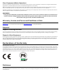
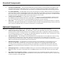
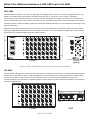
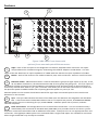
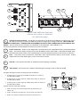
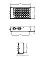
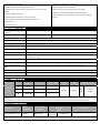
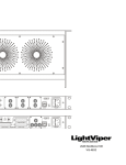
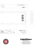
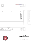
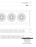
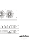
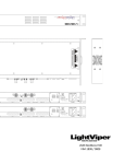
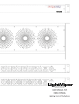
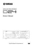
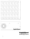
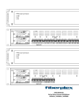
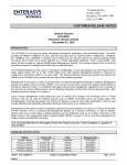
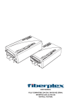
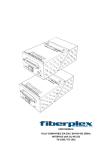
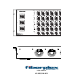
VRK-1832 Phantom Power 26 26 12 0 Made in the USA 12 26 0 Clip S1 12 26 0 Clip S2 12 26 0 Clip S3 12 26 0 Clip S4 12 0 Clip S5 Primary S1-S8 Phantom Power 26 12 26 0 12 26 0 Clip Aux 12 26 0 Clip S9 12 26 0 Clip S10 12 26 0 Clip S11 12 0 Clip S12 S13 S9-S16 Phantom Power 26 12 26 0 12 26 0 Clip 12 26 0 Clip S17 12 26 0 Clip S18 12 26 0 Clip S19 12 0 Clip S20 S21 S17-S24 Aux Phantom Power 26 12 26 0 Clip 12 26 0 Clip S25 12 26 0 Clip S12 12 26 0 Clip S27 12 26 0 Clip S28 12 0 S29 S25-S32 R1 Sync 1 3 2 R2 1 3 2 R3 1 3 2 TECHNOLOGIES, LLC fiberplex.com • 301.604.0100 USER MANUAL VIS‐1832/VIM‐1832 R4 1 3 2 R5 1 3 2 1 3 Warning for Your Protection 1. Read these instructions. 2. Keep these instructions. 3. Heed all warnings. 4. Follow all instructions. 5. Do not use this apparatus near water. 6. Clean only with a dry cloth. 7. Do not block any of the ventilation openings. Install in accordance with the manufacturer’s instructions. 8. Do not install near any heat sources such as radiators, heat registers, stoves, or other apparatus (including amplifiers) that produce heat. 9. Do not defeat the safety purpose of the polarized or grounding‐type plug. A polarized plug has two blades with one wider than the other. A grounding type plug has two blades and a third grounding prong. The wide blade or the third prong is provided for your safety. If the provided plug does not fit into your outlet, consult an electrician for replacement of the obsolete outlet. 10. Protect the power cord from being walked on or pinched, particularly at plugs, convenience receptacles, and the point where they exit from the apparatus. 11. Only use attachments/accessories specified by the manufacturer. 12. Use only with the cart, stand, tripod, bracket, or table specified by the manufacturer, or sold with the apparatus. When a cart is used, use caution when moving the cart/apparatus combination to avoid injury from tip‐over. 13. Unplug this apparatus during lightning storms or when unused for long periods of time. 14. Refer all servicing to qualified service personnel. Servicing is required when the apparatus has been damaged in any way, such as power‐supply cord or plug is damaged, liquid has been spilled or objects have fallen into the apparatus, the apparatus has been exposed to rain or moisture, does not operate normally, or has been dropped. The apparatus shall not be exposed to dripping or splashing. No objects filled with liquids, such as vases, shall be placed on the apparatus. “WARNING: To reduce the risk of fire or electric shock, do not expose this apparatus to rain or moisture.” General Installation Instructions Please consider these general instructions in addition to any product‐specific instructions in the “Installation” chapter of this manual. Unpacking Check the equipment for any transport damage. If the unit is mechanically damaged, if liquids have been spilled or if objects have fallen into the unit, it must not be connected to the AC power outlet, or it must be immediately disconnected by unplugging the power cable. Repair must only be performed by trained personnel in accordance with the applicable regulations. Installation Site Install the unit in a place where the following conditions are met: The temperature and the relative humidity of the operating environment must be within the specified limits during operation of the unit. Values specified are applicable to the air inlets of the unit. Condensation may not be present during operation. If the unit is installed in a location subject to large variations of ambient temperature (e.g. in an OB‐van), appropriate precautions must be taken. Unobstructed air flow is essential for proper operation. Ventilation openings of the unit are a functional part of the design and must not be obstructed in any way during operation (e.g. ‐ by objects placed upon them, placement of the unit on a soft surface, or improper installation of the unit within a rack or piece of furniture). The unit must not be unduly exposed to external heat sources (direct sunlight, spot lights). Ambient Temperature Units and systems by FiberPlex are generally designed for an ambient temperature range (i.e. temperature of the incoming air) of +5...+40 °C. When rack mounting the units, the following facts must be considered: The permissible ambient temperature range for operation of the semiconductor components is 0 °C to +70 °C (commercial temperature range for operation). The air flow through the installation must allow exhaust air to remain cooler than 70 °C at all times. Average temperature increase of the cooling air shall be about 20 C°, allowing for an additional maximum 10 C° increase at the hottest components. If the cooling function of the installation must be monitored (e.g. for fan failure or illumination with spot lamps), the exhaust air temperature must be measured directly above the modules at several places within the enclosure. Grounding and Power Supply Grounding of units with mains supply (class I equipment) is performed via the protective earth (PE) conductor integrated in three pin Phoenix™ connector. Units with battery operation (< 60 V, class III equipment) must be earthed separately. Grounding the unit is one of the measures for protection against electrical shock hazard (dangerous body currents). Hazardous voltage may not only be caused by defective power supply insulation, but may also be introduced by the connected audio or control cables. This equipment may require the use of a different line cord, attachment plug, or both, depending on the available power source at installation. If the attachment plug needs to be changed, refer servicing to qualified personnel. Class I Equipment (Mains Operation) Should the equipment be delivered without a matching mains cable, the latter must be prepared by a trained person using the attached female plug (Neutrik™ powerCON TRUE1) with respect to the applicable regulations in your country. Before connecting the equipment to the AC power outlet, check that the local line voltage matches the equipment rating (voltage, frequency) within the admissible tolerance. The equipment fuses must be rated in accordance with the specifications on the equipment. Equipment supplied with a 3‐pole appliance inlet (protection conforming to class I equipment) must be connected to a 3‐pole AC power outlet so that the equipment cabinet is connected to the protective earth. WARNING: If the ground is defeated, certain fault conditions in the unit or in the system to which it is connected can result in full line voltage between chassis and earth ground. Severe injury or death can then result if the chassis and earth ground are touched simultaneously. Warranty, Service and Terms and Conditions of Sale For information about Warranty or Service information, please see our published ‘Terms and Conditions of Sale’. This document is available on fiberplex.com or can be obtained by requesting it from [email protected] or calling 301.604.0100. Disposal Disposal of Packing Materials The packing materials have been selected with environmental and disposal issues in mind. All packing material can be recycled. Recycling packing saves raw materials and reduces the volume of waste. If you need to dispose of the transport packing materials, recycling is encouraged. Disposal of Used Equipment Used equipment contains valuable raw materials as well as substances that must be disposed of professionally. Please dispose of used equipment via an authorized specialist dealer or via the public waste disposal system, ensuring any material that can be recycled has been. Please take care that your used equipment cannot be abused. After having disconnected your used equipment from the mains supply, make sure that the mains connector and the mains cable are made useless. Declarations of Conformity Class A Equipment ‐ FCC Notice This equipment has been tested and found to comply with the limits for a Class A digital device, pursuant to Part 15 of the FCC Rules. These limits are designed to provide a reasonable protection against harmful interference when the equipment is operated in a commercial environment. This equipment generates, uses, and can radiate radio frequency energy and, if not installed and used in accordance with the instruction manual, may cause harmful interference to radio communications. Operation of this equipment in a residential area is likely to cause harmful interference, in which case the user will be required to correct the interference at their own expense. Disclaimer The information in this document has been carefully checked and is believed to be accurate at the time of publication. However, no liability is assumed by FiberPlex for inaccuracies, errors, or omissions, nor for loss or damage resulting either directly or indirectly from use of the information contained herein. Introduction Congratulations on your purchase of a LightViper™ VRK‐1832 (VIS‐1832) fiber optic audio snake head; a lightweight, flexible breakthrough for professional sound production. LightViper™ products are designed, engineered and manufactured by FiberPlex Technologies, LLC ‐ experts in fiber optics with decades of experience. Our work in audio and data communications products is known in US government applications worldwide. LightViper™ products combine our fiber optic technology with the highest standards in audio engineering. The VRK‐1832 You have purchased the LightViper™ 1832 system, a 32 x 8 Fiber Optic Transport System that has the function, look and feel of a traditional copper snake. Instead of traditional heavy multi‐conductor copper cable, LightViper™ fiber optic systems utilize lightweight, flexible, military tactical grade fiber‐optic cable or duplex PVC and plenum rated fiber for installation use. The Fiber Advantage Fiber optics offer many advantages over copper: Transmits light rather than electrons Transmission over greater distances (more than 20 Km) Complete electrical isolation Immunity to RFI and EMI Eliminates ground loop problems Can be routed overhead, through walls, or underground Avoids foot traffic while maintaining aesthetics Functional Considerations The LightViper™ VRK‐1832 is an active device. Because of this, there are some aspects of this new technology that require some slightly different thinking: The LightViper™ VRK‐1832 system requires AC Power at both the Stage (VRK‐1832) and the console (VIM‐1832) The VRK‐1832 system contains 32 microphone preamplifiers. In order to provide a transparent user experience, coarse gain is set using a 3 position switch at each input. Fine gain setting can be done at the input trim of the console for analog, or via digital attenuation for a digital console. All analog outputs are at Line Level Input and Output flexibility may eliminate the need for some of your outboard gear such as direct boxes. The LightViper™ VRK‐1832 is an active device, therefore do not attempt to connect intercom into the returns The returns in the VRK‐1832 cannot be “turned around” to provide (40) sends one way as with a traditional copper snake, as the electronics for the returns are contained in the VRK‐1832. Standard Components In its standard configuration, the LightViper™ 1832 system is made up of the following primary components. The Head End (VRK‐1832) — This is the box placed close to all the inputs. It can be placed on the stage or rack mounted with the optional VER‐1832 rack ears. This contains 32 high quality microphone preamplifiers and 8 analog line level outputs. Two optional fiber transmitters are included to facilitate splits from the stage location. The Tail End (VIM‐1832)— The VIM‐1832 is the console end solution for analog or AES3 connections. It provides 32 line level outputs as well as 32 AES digital outputs of the VRK‐1832 mic pre inputs. The user can choose between 8 line level analog inputs or 8 AES3 digital inputs to be passed to the VRK‐1832 analog outputs. An additional fiber through connector is provided to allow a tail end split of the 32 channel audio. Yamaha Interface (VIM‐MY32) – For applications using Yamaha consoles equipped with MYGDAI expansion slots, the VIM‐MY32 card set allow the fiber from a VRK‐1832 or VIS‐4832 to be connected directly to the console in place of the VIM‐1832. All audio I/O is achieved digitally through the card slot interface. Fiber Cable — For live production, tactical military grade fiber with Neutrik™ opticalCON Connectors is required between the VIM‐1832 and VIM‐1832. For installations where the fiber will be pulled through conduit, either PVC fiber or Plenum rated fiber with LC connector terminations is recommended. Optional Components Additional components can be added to the LightViper™ VRK‐1832 for increased functionality. Additional Split Box(es) (VIM‐1032) – The VIM‐1032 is similar to the VIM‐1832 mixer box in that it provides a parallel set of the snake’s 32 input channels, via an additional Fiber Cable, in applications where you need splits – for recording, broadcast, or monitor mixing. The VRK‐1832 Stage Box is fit with two “split” connectors for a total of three (1 VIM‐1832 (Primary) + 2 VIM‐1032 (splits)) outputs. Floor Box Enclosure – The VIS‐1832 is functionally identical to the VRK‐1832. The only difference is the housing. The VIS‐1832 is packaged to be a ‘Floor Box’ rather than rack mounted. This configuration can be used in situations where you just need to drop a snake head on the floor for easy access. All fiber connections on the VIS‐ 1832 are tactical due to the exposed nature of the enclosure. Wall Mounting Option – The VBZ‐1832 is functionally identical to the VRK‐1832. The only difference is the housing. The VBZ‐1832 is designed for a flush wall mount application, for example stage left/right stage mounting, house of worship or corporate meeting room applications. The VBZ‐1832 comes with a back box designed to be mounted between standard 16” center studs and the electronics are mounted to a flush wall plate. DMX Lighting Control – The DMX4i and DMX4o allow up to 4 universes of DMX lighting control to pass through the primary fiber connection as the 32x8 audio. The DMX4i/o boxes connect via the ‘Control’ port of the VRK‐ 1832. MD‐3 Multi control interface translator – In applications where you want RS‐422, RS‐232 or Midi control in an 1832 system, a pair of MD‐3 devices will translated this control protocol into TTL data for input to / output of the ‘Control’ connector on the VRK‐1832. Getting Started Initial Inspection Immediately upon receipt, inspect the shipping container for damage. The container should be retained until the shipment has been checked for completeness and the equipment has been checked mechanically and electrically. If the shipment is incomplete, if there is mechanical damage, or if the unit fails to operate notify FiberPlex and make the shipping materials available for the carrier's inspection. Chassis Mounting Mount the chassis using fasteners appropriate to your standard 19” rack enclosure. All four (4) mounting points MUST be utilized. Ensure that there exists adequate clearance for front and rear ventilation. The chassis should be located in an environment where an ambient temperature between 0° and 50° C can be maintained. If using the VIS‐1832 configuration, place the Stage Box in a location central to the majority of your signal sources. Making Connections The setup of a basic 1832 system is a quick and simple process. Connect a Fiber Cable between the primary fiber connection of the VRK‐1832 and the primary fiber connection of the Tail End device (VIM‐1832 or VIM‐MY32M) Make copper connections at both ends Connect AC power via the Neutrik™ powerCON TRUE1 connector Verify the ‘Sync’ light on both the Head and Tail units are green The more advanced functions of the LightViper™ VRK‐1832 are addressed later in this manual. NOTE: the signal coming out of a Tail unit into the console will be line level. When the gain switches on the VRK‐1832 are properly set, the signal going into the console will be very hot this is normal. Use line level inputs or engage input pads to achieve optimal signal‐to‐noise ratio. What’s the difference between a VRK‐1832 and a VIS‐1832 Functionally, the VRK‐1832 and VIS‐1832 are identical. The only difference is the packaging. VRK‐1832 The VRK‐1832 is cased in a 17” 5U rack package. It is designed for exclusive rack mounting applications. The power, fuse and control connections are located on the rear or ‘inside the rack’ surface. The optical connections can be mounted either on the front surface along with the audio connections or on the rear of the unit beside the power and control connectors. Front installation would be recommended for tactical and portable solutions. When ordering a VRK‐1832 with opticalCON connectors this is the default mounting of the optical connectors. Optionally, the optical connectors can be routed to the rear surface for connection inside of the rack. When ordering a VRK‐1832 with standard LC installation connectors, this is the default configuration. This provides protection for installation fiber inside the rack enclosure. Phantom VRK-1832 26 Power 26 12 0 Made in the USA 12 26 0 Clip 12 26 0 Clip S1 12 26 0 Clip S2 12 26 0 Clip S3 12 26 0 Clip S4 12 26 0 Clip S5 12 0 Clip S6 VRK-1832 Clip S7 Made in the USA S8 Primary Primary S1-S8 Tx Rx Phantom 26 Power 12 26 0 12 26 0 Clip 12 0 Clip S9 26 12 0 Clip S10 26 12 0 Clip S11 26 12 0 Clip S12 26 12 0 Clip S13 26 0 Clip S14 12 Clip S15 S16 Control Circuits Aux Aux S9-S16 Phantom 26 Power 12 26 0 12 26 0 Clip 12 0 Clip S17 26 12 0 Clip S18 26 12 0 Clip S19 26 12 0 Clip S20 26 12 0 Clip S21 26 0 Clip S22 12 Clip S23 S24 Universal S17-S24 90-250 V Aux 26 Power 12 26 0 12 26 0 Clip 12 26 0 Clip 12 26 0 Clip 12 26 0 Clip 12 26 0 Clip 12 26 0 Clip Clip Aux 50-60 Hz 12 0 Clip S12 S27 S28 S29 S30 S31 S32 R1 R2 R3 R4 R5 R6 R7 R8 US E F S25 E F Phantom US 1 AMP T1AL250V S25-S32 Sync 1 3 1 2 3 1 2 3 1 2 3 1 2 3 1 2 3 1 2 3 2 1 3 2 TECHNOLOGIES, LLC TECHNOLOGIES, LLC fiberplex.com • 301.604.0100 fiberplex.com • 301.604.0100 REAR (partial) FRONT Figure 1 VRK‐1832 shown with both optical mounting options VIS‐1832 The VIS‐1832 is designed to emulate the functionality of a traditional ‘floor box’. Its durable steel housing has rubber feet on the bottom and is sufficient weight to prevent cables from pulling the box over. Power, fuse, control and all fiber connections are on the side of the unit. Only tactical opticalCON connectors are recommended for the VIS‐1832. Installation grade LC fiber and connectors could be vulnerable in an exposed ‘floor box’ application. Phantom Power 26 26 12 0 12 26 0 Clip 12 26 0 Clip S1 12 26 0 Clip S2 12 26 0 Clip S3 12 26 0 Clip S4 12 26 0 Clip S5 12 0 Clip S6 Clip S7 S8 S1-S8 Phantom Power 26 12 26 0 12 26 0 Clip 12 26 0 Clip S9 12 26 0 Clip S10 12 26 0 Clip S11 12 26 0 Clip S12 12 26 0 Clip S13 12 0 Clip S14 Clip S15 S16 S9-S16 Phantom Power 26 12 26 0 12 26 0 Clip 26 0 Clip S17 12 26 0 Clip S18 12 26 0 Clip S19 12 26 0 Clip S20 12 26 0 Clip S21 12 0 Clip S22 12 Clip S23 S24 S17-S24 Control Circuits 26 0 Clip 12 26 0 Clip S25 12 26 0 Clip S12 12 26 0 Clip S27 12 26 0 Clip S28 12 26 0 Clip S29 12 26 0 Clip S30 US 12 E F 12 0 Clip S31 Aux Aux Primary US Power 26 E F Phantom 1 AMP T1AL250V Universal 90-250 V 50-60 Hz S32 S25-S32 R1 Sync 1 3 2 R2 1 3 2 R3 1 3 2 R4 1 3 2 R5 1 3 2 R6 1 3 2 R7 1 3 2 R8 1 3 2 FRONT SIDE Figure 2 VIS‐1832 Features 1 3 Phantom VRK-1832 Power 26 26 12 0 Made in the USA 12 26 0 Clip 12 12 26 0 Clip S1 26 0 Clip S2 12 26 0 Clip S3 12 12 26 0 Clip S4 12 26 0 Clip S5 0 Clip S6 Clip S7 S8 Primary S1-S8 Phantom Power 26 12 26 0 12 26 0 Clip Aux 12 12 26 0 Clip S9 26 0 Clip S10 12 26 0 Clip S11 12 12 26 0 Clip S12 12 26 0 Clip S13 0 Clip S14 Clip S15 S16 S9-S16 Phantom Power 26 12 26 0 12 26 0 Clip 12 12 26 0 Clip S17 26 0 Clip S18 12 26 0 Clip S19 12 12 26 0 Clip S20 12 26 0 Clip S21 0 Clip S22 Clip S23 S24 S17-S24 Aux Phantom Power 26 12 26 0 Clip 12 26 0 Clip S25 12 12 26 0 Clip S12 26 0 Clip S27 12 26 0 Clip S28 12 12 26 0 Clip S29 12 26 0 Clip S30 0 Clip S31 S32 S25-S32 R1 Sync 1 3 2 R2 1 3 2 R3 1 3 2 R4 1 3 2 R5 1 3 2 R6 1 3 2 R7 1 3 2 R8 1 3 2 TECHNOLOGIES, LLC fiberplex.com • 301.604.0100 5 4 2 Figure 3 VRK‐1832 Front shown with optional front mounted opticalCON connectors Input ‐ Each of the 32 inputs on the Stage Box is a Neutrik, XLR/TRS combo connector. All inputs accept balanced or unbalanced signals, eliminating the need for adapters and DI boxes. The XLR inputs of the VIS‐1832 have an input impedance of 1.8KΩ while the TRS has an input impedance of 1.8KΩ. 1 2 Return ‐ Each of the 8 returns are made via Neutrik, XLR, male connectors. Returns are all line‐level. Phantom Power ‐ 48V Phantom Power is switch‐selectable in groups of eight inputs (1‐8, 9‐16, 17‐24, 25‐32) When switched on, the Phantom Power LED for that group will glow green. The 1/4” inputs of the Neutrik Combo connectors on the VIS‐1832 are normalled so that phantom power is disconnected on a channel by channel basis when a 1/4” jack is inserted. This allows you to use these connectors in a bank that has phantom power enabled without fear of putting phantom power on your 1/4” line. 3 Phantom power on the console should be turned off for Light Viper connected inputs as this could cause distortion on the channel. Sync ‐ The Sync LED indicates the status of the fiber optic link between the Stage Box and the Mixer Box. It has three states: SOLID RED indicates there is no optical link present, ALTERNATING GREEN AND RED means the unit is searching for sync, SOLID GREEN ‐ indicates optical link is present, and OFF indicates no power. 4 Fiber Connections ‐ Each Stage Box has one to three fiber connections. The one marked ‘Primary’ should always be connected to the Mixer Box (VIM‐1832) as it provides clock for the entire system. Any other connections would be made to additional send boxes. Always be sure to use appropriate fiber and connectors. The LightViper 1832 system uses multimode fiber. Single mode optics are available for situations where single mode fiber may already be installed. 5 5 VRK-1832 Made in the USA Primary Tx Rx 6 6 5 7 Control Circuits Aux 7 Universal 90-250 V Aux 50-60 Hz Control Circuits E F E F US E F US Aux TECHNOLOGIES, LLC fiberplex.com • 301.604.0100 Aux US 1 AMP T1AL250V E F 8 US Primary 1 AMP T1AL250V 8 Universal 90-250 V 50-60 Hz Figure 4 VRK‐1832 Rear (left) with optional rear mount LC connectors VIS‐1832 Side (right) Control Circuits Connector ‐ This RJ‐45 jack provides (3) bi‐directional CMOS or TTL data lines (up to 38.4 KHz from Stage to FOH and 2MHz from FOH to Stage) plus voltage and GND. THIS IS NOT AN ETHERNET CONNECTOR —CONNECTING AN ETHERNET DEVICE TO THIS CONNECTOR COULD DAMAGE THE DEVICE. The Pin‐Outs for this connector are detailed in the Appendix. Most CMOS or TTL functions/equipment can be adapted to make use of this connector. 6 Power Connector ‐ Power to the Stage Box is provided with the supplied Neutrik™ powerCON power cable. The internal power supply can accept 90‐260V at either 50 or 60Hz. VIM‐1832 and VIM‐1032 units use standard IEC power cables. The supplied power cord will be appropriate to the country of delivery. 7 8 Fuse - The power fuse is a 5x20 mm, 1A Slo‐Blo. Only replace the fuse with an exact match. If after replacement the fuse blows again, return the unit for service. 9 Clip LED – The Clip LED will flash at 3 dB below peak clipping. (+16 dBu). 10 Gain Switch – Each input has 3 switch‐selectable gain settings: 0 dB, 12 dB, and 26 dB The gain settings correlate to output levels as follows: 10 A setting of 0, an input signal of 0dBu will produce an output at the VIM‐1832 of 0dBu. 9 A setting of 12, an input signal of ‐12dBu will produce an output at the VIM‐1832 of 0dBu. A setting of 26, an input signal of ‐26dBu will produce an output at the VIM‐1832 of 0dBu. Typical uses for each gain setting: 0 dB ‐ Line level instruments/equipment (eg. Keyboards, CD player, etc) 12 dB ‐ Condenser microphones, “hot” dynamic microphones. 26 dB ‐ Low output condenser microphones, dynamic mics. 3 1 This page left intentionally blank Functional Block Diagram AIn 1 AIn 2 AIn 3 AIn 4 AIn 5 AIn 6 AIn 7 AIn 8 AIn 9 AIn 10 AIn 11 AIn 12 AIn 13 AIn 14 AIn 15 AIn 16 AIn 17 AIn 18 AIn 19 AIn 20 AIn 21 AIn 22 AIn 23 AIn 24 AIn 25 AIn 26 AIn 27 AIn 28 AIn 29 AIn 30 AIn 31 AIn 32 AOut 1 AOut 2 AOut 3 AOut 4 AOut 5 AOut 6 AOut 7 AOut 8 DOut 1/2 DOut 3/4 DOut 5/6 DOut 7/8 TTL CTL PTx PRx S1Tx S2Tx VIS-1832 (G2) AOut 1 AOut 2 AOut 3 AOut 4 AOut 5 AOut 6 AOut 7 AOut 8 AOut 9 AOut 10 AOut 11 AOut 12 AOut 13 AOut 14 AOut 15 AOut 16 AOut 17 AOut 18 AOut 19 AOut 20 AOut 21 AOut 22 AOut 23 AOut 24 AOut 25 AOut 26 AOut 27 AOut 28 AOut 29 AOut 30 AOut 31 AOut 32 DOut 1/2 DOut 3/4 DOut 5/6 DOut 7/8 DOut 9/10 DOut 11/12 DOut 13/14 DOut 15/16 DOut 17/18 DOut 19/20 DOut 21/22 DOut 23/24 DOut 25/26 DOut 27/28 DOut 29/30 DOut 31/32 PRx WCLK Out VIM-1032 AOut 1 AOut 2 AOut 3 AOut 4 AOut 5 AOut 6 AOut 7 AOut 8 AOut 9 AOut 10 AOut 11 AOut 12 AOut 13 AOut 14 AOut 15 AOut 16 AOut 17 AOut 18 AOut 19 AOut 20 AOut 21 AOut 22 AOut 23 AOut 24 AOut 25 AOut 26 AOut 27 AOut 28 AOut 29 AOut 30 AOut 31 AOut 32 DOut 1/2 DOut 3/4 DOut 5/6 DOut 7/8 DOut 9/10 DOut 11/12 DOut 13/14 DOut 15/16 DOut 17/18 DOut 19/20 DOut 21/22 DOut 23/24 DOut 25/26 DOut 27/28 DOut 29/30 DOut 31/32 AIn 1 AIn 2 AIn 3 AIn 4 AIn 5 AIn 6 AIn 7 AIn 8 DIn 1/2 DIn 3/4 DIn 5/6 DIn 7/8 TTL CTL PTx PRx WCLK In WCLK Out S1Tx VIM-1832 (G2) Duplex Fiber Cable Specifications 5.75 [146.0] 8.72 [221.4] 19.00 [482.6] .41 [10.3] 18.33 [465.5] 17.00 [431.8] 3.97 [100.8] .30 [7.5] Figure 5 VRK‐1832 Dimensions .31 [7.9] 4.00 [101.6] 8.72 [221.5] 14.00 [355.6] 7.00 [177.8] 12.00 [304.8] Figure 6 VIS‐1832 Dimensions • 32 x 8 fiber optic snake • High quality Neutrik™ connectors • Cable runs over 1.25 miles with no loss • Heavy gauge steel construction • Rack mount and wall panel options available • Rugged fiber cable smaller in diameter than standard mic cable • Optional lossless 3 way split of all 32 Channels • 24 bit / 96kHz sampling • Extended range and flexibility means limitless routing options • 48 Volt Phantom power on every channel • Every channel accepts balanced or unbalanced connections... No need for DI’s GENERAL SPECIFICATIONS Total Harmonic Distortion + Noise*1 Less than 0.01% 1 KHz @ +4 dBu Frequency Response ± 0.5 dB 20‐20kHz @ +16 dBu Dynamic Range 102 dB Crosstalk 5 dB above noise floor Sampling Rate 24 bit / 96kHz or 24 bit / 48 kHz Latency 630 s one way, analog input to analog output, 20s one way, digital input to digital output. Operating Temp 0 to +50°C ambient temperature. Input Channel LED LED (red) lights when input reaches 3dB below clipping. (+16dBu) Sync LED LED (green) indicates optical link OK, LED (red) indicates problem with optical link, LED (off) indicates no power. AC Power Universal 90‐250 VAC, 50/60 Hz, Neutrik PowerCon connector with fuse Max Current Rating 0.473 mA @ 90V On / Off Control Date + MIDI RJ‐45 connector for logic level control, CMOS or TTL at 2 MHz max per channel. Dimensions 12.5" L X 8.75" W X 4 H (32cm x 22cm x 10 cm) Weight 12 lbs (5.44 Kg) *1‐Hum & Noise are measured with an AES17 compliant filter at 20 kHz. Temperature condition @+10 ‐ +25° C. INPUT CHARACTERISTICS Connection Gain Voltage Gain*2 Analog Inputs 0 0 (0 dB) 1.65 Vrms ‐83 dBu 12 4 (12dB) 412.5 mVrms ‐83 dBu 26 20 (26dB) 82.5 mVrms ‐83 dBu 1‐32*4 Sensitivity*3 S/N ref +0dBu Overload Clipping +16 dBu +19 dBu Input Impedance XLR TRS 1.8 K 10 K *1–Hum & Noise are measured with an AES17 compliant filter at 20 kHz. Temperature condition @+10 ‐ +25° C. *2–0dBu is referenced to 0.775Vrms. *3–Sensitivity is the lowest level that will produce an output of +4dBu (1.23V). *4–All XLR connectors and D25 connections are balanced OUTPUT CHARACTERISTICS Connection Source Impedance Analog Outputs 1‐8*1 150 For Use With Nominal 600 Lines Output Level*2 Before Clip Nominal Max +4 dBu (1.23 V) +19 dBu (7 V) *1–All XLR connectors and D25 connections are balanced. *2–0 dBu is referenced to 0.775 Vrms. Connector*1 DB‐25, Tascam™ DA‐88 pinout, 8 OPTICAL CHARACTERISTICS Connector*1 Installation Tension Operating Tension Min Bend Radius Crush Resistance Weight Fiber‐Optic Cable*2 400 lbs 130 lbs 3.7" 228 lb/in2 19 lbs / 1000' Attenuation Bandwidth Numerical Aperture System Optical Data Rate System Operating Distance 1 dB/Km @1300 nm 500 MHz/Km @ 1300 nm 0.275 122 Mbs 2 Km (1.25 mi) Optical Fiber*3 *1–Neutrik™ opticalCON, *2–Four Channel Tactical Break Out Cable, 0.30"(7.5mm) Outer Diameter, Kevlar™ Strength Member *3–Graded Index, Multimode, Dual Window (850/1300nm) CONTROL CIRCUITS RJ‐45 PIN OUTS 1. GND 2. TX1 3. TX2 4. TX3 5. RX1 6. RX2 7. RX3 UMVRK1832 140807 18040-412 Guilford Rd. • Annapolis Junction, MD 20701 fiberplex.com • [email protected] • 301.604.0100