1
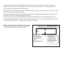
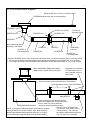
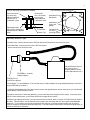
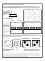
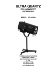
1
Performance Trends’ “EZ Flow”
EZ Flow is a kit which allows engine builders build a computerized flow bench from materials available at most
any hardware store. First you must build a bench following the parts list, plans and suggestions below.
Parts List
Qty
Part Number
Source/Description
1
PFAEZBA
1
PFAEZO-x.xx
3
PFAEZTB.125
3
2
PFAEZPP.125
PFAEZFL4
1
1
PFAEZMPT
PFAEZ90-4
2
2
2
1
1
PFAEZPVC4-19
PFAEZPVC4-10
PFAEZFT
PFAEZRDx.x
PFAEZOx.xx
1
PFAEZFS-4
1
1
1
OFPB
OBA
OFCV
Std Bore Adapter, part of Performance Trends EZ Flow System with SB Chevy and SB
Ford bolt patterns and approx 4.03” ID (other bolt patterns available)
Flow Orifice (x.xx is diameter), part of Performance Trends EZ Flow System Available
sizes are 2.5” (400 CFM), 2” (250 CFM), 1.5” (150 CFM), 1.0” (75 CFM)
24” lengths of 1/8” clear PVC tubing for routing pressure to sensors in Black Box, part of
Performance Trends EZ Flow System
1/8” NPT to 1/8” barbed hose fitting (Ace Hdwe 4013108)
4” PVC flanges w 6” bolt circle holes (NIBCO 4851 Genova 75141) Note that these
may have to be drilled to match the bolt pattern of the PFAEZO-x.xx orifice, and have
the face sanded or ground smooth to provide an air tight seal using the PFAEZFT.
4” PVC to male pipe thread adapter (NIBCO 4084, Genova 70440)
4” PVC 90 deg streamlined elbow (NIBCO 4807, Genova 72840, Genova 73840
for a more gradual bend)
19” length of 4” schedule 40 PVC straight tubing
10” length of 4” schedule 40 PVC straight tubing
24” lengths of light foam tape/weather stripping
Rubber reducers, 4” to x.x inch (available sizes, 4”, 3”, 2.5” and 2”)
6” square calibration orifice plate with x.xx inch diameter sharp edged orifice (available
sizes are 3.0, 2.5, 1.875, 1.5 and 1.0 inches)
4” grid flow straightener (2’x4’cut from white egg crate Home Depot ceiling
“lighting panel” 74507 43200)
Optional Flow Plenum Box
Optional Fabricated bore adapter, for heads other than SB Ford or SB Chevy
Optional Flow Control Valve, to help maintain a constant test pressure
For “High Flow” 6” PVC EZ Flow Systems
1
PFAEZBA6
2
PFAEZFL6
1
PFAEZMPT6
1
PFAEZ90-6
6” Bore Adapter, part of Performance Trends EZ Flow System with SuperFlow ™
flow bench bolt pattern for your bore adapter.
6” PVC flanges w 9.5” bolt circle holes (McMaster Carr 4881K221). Note, use the
PFAEZFT to provide an air tight seal. Visit www.mcmaster.com to order.
6” PVC to male pipe thread adapter (McMaster Carr 4880K161). Visit
www.mcmaster.com to order.
6” PVC 90 deg elbow (Lowes Charlotte Pipe 6" PVC 90° Elbow Item #: 53037
Model #: PVC 00300 1600). Visit www.lowes.com to order.
Notes for assembly:
The diagrams given here are just a couple of assembly layouts. Due to space constraints, your shop layout, etc,
you may decide to do things differently. Here are some tips to keep in mind for all systems.
Leaks are a major contributor to flow bench inaccuracies and non-repeatable readings. Take precautions to
eliminate all leaks. If you construct portions of your flow system out of wood, be sure to laminate or paint with
several coats to eliminate the porosity of the wood.
Generally, the more the volume between the head (or test piece) and the flow orifice the better, it it doesn’t
introduce leaks. The system shown on the next page with the plenum shows this extra volume, so the air can
“stabilize” between the head and the flow orifice. If you use a plenum, be sure that the air stream from either
the head or the flow orifice are well separated, so the flow velocity from one does not influence flow on the
other.
2
You must measure the Test Pressure from a relatively “quiet” area, away from flow velocity. If you use a
plenum, tap into a remote corner of the plenum. If you use just the 90 deg elbow, Tee into the flow orifice
pressure tap on the side nearest the head (test piece) .
Pressure taps to record pressure across Flow Orifice should be as close to orifice as practical, to be in the “dead
flow” area in corners. See Detail to right.
For best accuracy/repeatability, keep the amount of straight PVC tubing before and after the flow orifice to 15”
minimum (30” total). If space allows, longer is better.
For ease of assembly, it is recommended that the joint between PFAEZPVC4-10 and PFAEZ90-4 be easily
assembled and disassembled. You may want to seal this with heavy grease or tape, and attach the 2 pieces with
screws or bolts instead of PVC cement or some other type of sealant.
NOTE: Orifice plates must be no larger than half the inside
diameter of the PVC tubing it is mounted in. For example,
a 2” orifice is the maximum size for a 4” PVC tube.
To Head
If needed, you
can Tee into this
pressure tap for
the test pressure
sensor.
Orifice Plate in tube
Pressure taps
should be as close
to orifice plate as
possible, to avoid
taps being exposed
to air velocity.
3
EZ Flow System Build Diagram
Bench top with 5.2-5.5” hole cut for bore adapter
PFAEZBA bolted to bench top via mounting holes
PFAEZMPT
PFAEZO-x.xx (orifice)
PFAEZPVC4-10 ***
PFAEZPP.125 * **
To Vacuum/
Pressure Source
PFAEZPP.125 *
PFAEZ90-4
Recommend this joint be
temporary. See Notes.
PFAEZFL4
PFAEZFS-4
Flow Straightener
PFAEZPVC4
PFAEZFL4
PFAEZRDx.x
(reducer)
PFAEZPVC4
PFAEZFS-4
Flow Straightener
* Keep the PFAEZPP.125 as close as practical to the orifice plate, to ensure the pressure seen is out of the air flow
** You can use this pressure as both a flow pressure and as the test pressure for the Black Box via a Tee fitting
*** The length from the top of the PFAEZBA to the PFAEZ90-4 (90 deg elbow) should be 10” min., longer is better
OBA Optional Bore Adapter fabricated to
adapt to user’s cylinder head or test piece
Suggestions for controlling
the test pressure, either
with a restrictor valve or a
bleed valve.
Tap into a remote corner of the plenum for Test Pressure
5 pipe diameters minimum. See NOTE below.
Optional OFCV
Keep air flows from bore adapter and flow
orifice well separated so flow velocities have
time to “settle out” and not influence
OFPB Optional Plenum Box
the flow or pressure the other air flow.
The OFCV valve will restrict flow.
NOTE: If you want to control test pressure with either a restrictor
You can also use a “bleed” valve to
valve (like the OFCV), or with a “bleed” valve, these should be
control pressure. This valve can
placed 5 pipe diameter away from flow orifice (30” for 6” pipe).
typically be smaller than the pipe size,
You can also reduce pipe size at this point for easier building.
say, 2-3” valve for 6” main pipe.
4
Notes on Mounting PFAEZBA Bore Adapter
Piece mounted on
top, like a bore
adapter for different
cylinder size, or
a calibration orifice
¼ 20 Threaded mounting holes
Be sure that
the ¼ 20 screws
do not touch
when tightened,
if top bolt is used
Small Block Ford
Bolt pattern
Small Block
Chevy bolt
pattern
Optional Mounting:
Use 4 10x32 countersunk
flathead screws in tapered
holes.
PFAEZBA
Bench Top
Tapered holes
for 10x32
mounting screws
Vacuum Source Tips
For Intake Flow, connect vacuum hose to EZ Flow System and let pressure hose blow into room
For Exhaust Flow, connect pressure hose to EZ Flow System
and let vacuum hose suck from room
Vacuum/Pressure Source
Like a Shop Vac or
a higher pressure & flow
source fabricated by user **
PFAEZRDx.x (reducer)
Rubber Adapter *
PFAEZPVC4-19
from EZ Flow System
* Home Depot ™ or Ace Hardware ™ have a wide array of rubber adapters in the plumbing department, one brand
being PIPECONX by UniSeal ™
** Grainger and McMaster Carr have both vacuum motors and large diameter vacuum hose where you can fabricate
a high capacity vacuum/pressure source
To produce more than 20” water test pressure, you will most likely need 2 stage vacuum motors. To produce more
than 30” water test pressure, you will most likely need 3 stage vacuum motors.
To build a high capacity flow bench, you need several vacuum motors, about 1 for each 70 CFM of flow you want at
28” water. This will require a lot of electrical power (amps), and most likely 220 VAC and a good, knowledgeable
electrician. You must also reduce all flow restrictions to a minimum, so all the pressure/vacuum can be used to
produce a pressure drop across the head (test piece). This also means the flow orifice must be sized quite large, so
it does not become too restrictive.
5
Vacuum Source, Custom Build “Shop Vacuum”
If you want more flow capability than a large Shop Vacuum, you can build one following the basic outline below.
Contact us for typical part numbers for good vacuum motors. Each motor requires about 10 amps 110 VAC and
provides 50 to 80 CFM at 28”, depending on EZ Flow details.
¾” plywood box top view
vacuum motor
wood or metal ring
with hold down bolts
to hold motor in
place
hole in ¾” plywood divider
end view
side view
Note: Use LOTS of
screws to hold plywood box together
as the pressures
inside over a large
area create LOTS of
force.
High Pressure Side
Low Pressure Side
(suction)
Routing of air: The easiest method is to attach 2 large hoses, one to the top high pressure side and one to the
bottom low pressure side. Then you can route the air as shown in the previous Figure of the shop vacuum. A more
permanent air routing/diverting method is outlined below.
Steel “diverter” plate
4 holes in end of box
Route these 2 holes permanently
to EZ Flow System, with Y hose
fitting or with a plywood chamber
on the end of the box.
These 2 holes can
be open to room
air.
High pressure going
to EZ Flow (exhaust flow)
Low pressure (suction) to
EZ Flow (intake flow)
High Pressure Side
Low Pressure Side
Top 2 holes are on the High Pres. Side of box
Bottom 2 holes are on the Low Pres. Side of box
Tips: It is easiest to have 2 wooden end panels, each with 4 holes, with the diverter plate sandwiched between them.
Space the 2 panels apart with washers for a tight clearance. Fasten together with bolts. Use one large bolt as the
pivot for the diverter plate. You can get fancy with bearings or bushings if you want. Leaks here in this box do not
affect accuracy, just the efficiency of how much total CFM you can generate.
6
Instructions for Black Box Hookup to Flow Bench
Once you’ve built your EZ Flow flow bench, you will connect the Black Box. Performance Trends’ “Black Box” data logger will
record data from your EZ Flow flow bench to greatly enhance your flow bench testing. The 2 figures below give an explanation of the
various connections to the Black Box.
DB9 w male
pins connector
to communicate
to computer.
You MUST use
cable provided
by
Performance
Trends.
Power Jack
(12 volt DC,
300 mAmp)
DB9 w female
sockets
connector for
Swirl Meter
input.
Frequency Inputs
(typically not used
and are not included
on later Black
Boxes)
Enable Foot Switch
To enable the use of a foot or hand switch
for recording data with the Black Box, you
must enable the switch. Do this by
clicking on Options in the Electronics
Reading screen, then clicking on BB2
Foot Switch, and select which
temperature channel to use for the Foot or
Hand Switch. Typically this will be “Use
Flow Temp (T2) Channel” because “Test
Temp” is used for recording temperature
of the air flowing through the test piece.
If you want to record temperature on the
same channel as a switch is attached, you
need a special “Tee” harness from
Performance Trends.
Power light indicator
High Pressure side
of Pitot Tube sensor
High Pressure side of
Inclined Manometer
(flow pressure)
High Pressure side of
Vertical Manometer
(test pressure)
Test Temperature
(temperature of air
passing through head
or test piece)
Flow Temperature (temperature of air
passing through flow orifices). Black Box II
foot switch can go here or to Test Temp.
See figure below.
7
Bore adapter
Valve Opener
and Lift
Measurement
Vacuum motors for flow source
Flow Control Valve to set Test Pressure, may
not be necessary for standard Flow Tube
Flow Orifice
Flow Tube
with Orifice
Aux Pres. or Pitot
Tube Pres. Low
Aux Pres. or Pitot
Tube Pres. High
Cylinder Head
High pressure tap on pitot tube.
Low pressure tap on pitot tube
The pressure tap for test pressure (measuring pressure under the head) should be placed in a “dead” flow area,
and not in a location where air is rushing by it. This produces a Bernoulli “suction” pressure which is not
correct. You can also Tee into the pressure tap on the head side of the flow orifice pressure taps, as shown in
picture on page 2. However, due to flow losses, flow straighteners, etc, this pressure is not exactly the same as
the pressure directly under the head.
8
Software Setup
With the Black Box connected, you will want to setup the software. Follow the process outlined in Examples 4.1 and 4.2 in the
manual. When doing the Flow Bench Specs setup, follow the instructions outlined below.
NOTE: There are demo movie files on our website which can help you get “up to speed” quickly. On
our website, click on Support, then Movie Demo Files, then find the Port Flow Analyzer movies.
First, open up the example test called “EZ Flow Example”.
Click on File at upper left corner of main
screen, then “Open (from all saved tests)”.
Then in this Open Test File screen, choose (click on) “Examples” in the lower right corner for the folder, then choose (click on) “EZ
Flow Example” in the upper left corner, then Open in the lower left corner.
This will load several test and flow bench settings to get you up and running quickly.
Open the “EZ Flow Example” File
Choose the EZ Flow Example
test file, then click on Open in the
lower left corner.
Click on
File, then
Open (from
all saved
tests)
Choose
Examples
for the
Folder
9
Confirm that these critical specs are correctly set in this EZ Flow Example test file, as shown below.
EZ Flow System Setup in Port Flow Analyzer Software
Click on Flow Bench at top of
Main Screen to bring up Flow
Bench specs screen shown here.
Select EZ Flow System for the
Flow Bench Type. Most specs in
this screen are now disabled and
are being set automatically by the
software.
Click on Find Com Port button to
have the program look for your
Black Box II. Even if you are using
a USB adapter, it will still show up
as a Com Port.
Click on See Details button to
bring up screen shown below.
Enter both the Offset and
Factor for Test Pres.
sensors as shown here.
These numbers (-133
and .055) are
approximate, but work
well for most situations.
For OLDER boxes with
ASCX sensors (plastic
pressure taps extend
above top of box), these
numbers change to -80.5
and .038 respectively.
For added accuracy, you
can also click on this
Calibrate button and
follow the program
instructions to calibrate
the sensor to a water
manometer. See Figure
on next page.
10
Calibrating the Test Pressure Sensor with a Water Manometer
Tee in a water manometer to the test pressure line to
calibrate the test pressure sensor in the Black Box
A water manometer can be as simple as a loop of clear plastic hose with colored water filling a little over half of the
hose. It is much easier to work with a “tall” manometer, where the total height of the loop is 40 inches or more. The
pressure you record is the total difference in height of the water levels. See Appendix 2 in the Port Flow Analyzer’s
user manual.
Once the Test Pressure (vertical manometer) sensor has been calibrated, or had estimated readings entered, you
can calibrate the entire EZ Flow Flow Bench following the procedure outlined in the figures on the next page.
11
Calibrating the EZ Flow System
Click on Calibrate, then select either Intake
or Exhaust for the flow direction to calibrate.
Enter the diameter of the orifice
you have installed on the EZ Flow
system as pictured below.
Click on Measure Flow Data and
follow the program instructions.
You will first let the program record
zero pressures (with no flow,
bench off). Then you will turn on
the bench and record pressures
for this known orifice size. The
results will be shown at the top as
“New Full Range CFM”.
Click on the Use Calc Value to
keep this new calibration.
IMPORTANT: You can estimate the New Full Range CFM you should get from this
calibration by squaring the diameter of the flow orifice in the tube and then multiplying by
50. For example, for a 2.5” orifice, it should be approximately 2.5x2.5x50 = 312.5 CFM. If
your calibration does not come close to this (within 10%), double check what you are doing.
Make (or purchase from Performance Trends) an orifice plate
to bolt to the Bore Adapter where the head (test piece) would
normally bolt. Seal for leaks.
12
Depending on various combinations of settings, it may be necessary to set the Preference under the “Gen. Operation,
cont.” tab of “Black Box Reads +/- Pres.” to “Yes (NO checking)”. See Figure below.
Preference Settings
Click on Preferences
Then set Black Box Reads +/- Pres. to “Yes (NO checking)”
EZ Flow w Black Box.doc
13
6" EZ Flow System's Bore Adapter and Assembly
14