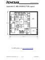
1
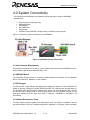
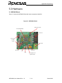
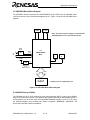
A pplica t io n s E n g in e e r in g
Powerful Processors – Easy to Use™
SKP38602
User's M anual
Rev. 1.0
March 2006
w w w.renesas.com
Applications Engineering
Table of Contents
1.0 Introduction ................................................................................................................. 2
2.0 Contents of Product Package ..................................................................................... 3
3.0 Limited Guarantee and Support .................................................................................. 4
4.0 System Connectivity.................................................................................................... 5
4.1 Host Computer Requirements.................................................................................. 5
4.2 SKP38602 Board ..................................................................................................... 5
4.3 E8 Debgger ..............................................................................................................5
4.4 Software Development Tools ................................................................................... 5
4.4.1 HEW (High-performance Embedded Workshop) ............................................... 6
4.4.2 NC30WA Entry Version...................................................................................... 6
4.4.3 HEW Debug Interface ........................................................................................ 6
5.0 Hardware..................................................................................................................... 7
5.1 SKP38602 Board ..................................................................................................... 7
5.2 SKP38602 Board Block Diagram ............................................................................. 7
5.3 H8/38602 Group of MCUs........................................................................................ 8
5.4 SKP38602 Board Jumper Configuration .................................................................. 9
5.4.1 JP1: MCU (U1) Power........................................................................................ 9
5.4.2 JP2: Xout............................................................................................................ 9
6.0 System Operation & Limitations................................................................................ 10
6.1 Kernel (ROM Monitor) Introduction ........................................................................ 10
6.2 Pin and Peripheral Limitations ............................................................................... 10
6.3 Memory Map .......................................................................................................... 11
6.4 Register Operation Limitations............................................................................... 11
6.5 Limitations on Interrupts......................................................................................... 11
6.6 Stop or Wait Mode Limitations ............................................................................... 12
6.7 User Program’s Real-Time Capability.................................................................... 12
6.8 Performing Debug Using Symbols ......................................................................... 12
7.0 SKP38602 Board Specifications ............................................................................... 13
7.1 Hardware Specifications ........................................................................................ 13
7.2 Power Supply Requirements.................................................................................. 13
7.3 Operating Environment .......................................................................................... 13
Appendix A. Troubleshooting Guide ............................................................................... 14
Appendix B. Reference Manuals..................................................................................... 17
Appendix C. Expansion Headers .................................................................................... 18
Appendix D. SKP38602 Schematics............................................................................... 19
Appendix E. SKP Board Dimensions .............................................................................. 20
SKP38602 User’s Manual Rev. 1.0
March 2006
Applications Engineering
1.0 Introduction
The SKP38602 StarterKit Plus (SKP) is a low-cost development environment for evaluating
H8/Super Low Power (SLP) series of microcontrollers (MCU) using the H8/38602 and Renesas
software development tools. The kit comes with a complete software development tool chain
including, HEW (IDE, GUI, Debugger), C-compiler, assembler, and linker, and the E8 in-circuit
Debugger.
A real-time, source-level debug environment is implemented using the HEW debugging interface
with the E8 hardware. The E8 also allows for programming H8/SLP devices within HEW.
The E8 and firmware provide a convenient USB (Universal Serial Bus) interface between the
SKP38602 board and the host PC. This interface reduces resource requirements on the
H8/38602 MCU, allows faster code downloads and, can also be used with many other Renesas
Flash MCU’s, SKP’s, and user’s target boards.
SKP38602 User’s Manual Rev. 1.0
2 / 19
March 2006
Applications Engineering
2.0 Contents of Product Package
This section describes the contents of the SKP38602 product package. When unpacking your
SKP38602, please check to see that all products listed below are included.
2.1 SKP38602 StarterKit Plus Product List
Table 2-1 lists the products included in the SKP38602.
Table 2-1 SKP38602 Product List
Product Name
SKP38602 Board
E8 Debugger
Quantity
1
1
Mini USB Cable
Quick Start Guide
1
1
SKP CD-ROM
1
Promotional CD
-
Remark
H8/38602 SKP Board
HEW Debugger/ USB
Programmer Interface Device
(includes 14pin ribbon cable)
Connects E8 to the Host PC
Assists user in installing the
tools and launching them for the
first time.
Auto-install program
HEW (IDE), C-compiler,
assembler, and linker
Manuals
Tutorials
Sample programs
Evaluation versions of 3rd party
tools may be included with the
kit
2.1.1 SKP CD-ROM
The CD-ROM contains the electronic manuals and software necessary for developing programs.
Your computer must have Netscape Navigator® or Microsoft®’s Internet Explorer to view the
help files and Adobe Acrobat Reader to view the manuals.
Insert the enclosed CD into your computer and SKP installer will auto-start. The SKP installer
program will create a ‘C:\Renesas’ and ‘C:\Workspace’ folder on your PC. Documentation,
sample code, and other SKP related files are in the ‘C:\Renesas\SKP38602’. HEW is installed in
the ‘C:\Program files\Renesas’ folder by default.
If the SKP installer program does not start up, browse the CD’s root folder and double-click on
‘skp_installer.exe’ to start installation.
SKP38602 User’s Manual Rev. 1.0
3 / 19
March 2006
Applications Engineering
3.0 Limited Guarantee and Support
Renesas Technology America, Inc., warrants the SKP38602 to be free from component or
assembly defect for a period of 180 days from the date of purchase. Settlement is limited to repair
or replacement of the product only. Renesas Technology America, Inc., does not assume any
liability arising out of the application or use of any product, circuit or procedure described herein.
No other liability or warranty apply, expressed or implied. Software warranty is limited to
replacement of the CD only. While every attempt has been made to ensure accurate
documentation, Renesas Technology America, Inc., cannot be held responsible for error or
omissions and reserves the right to make changes without further notice.
Warning!
The MCU on this product, the H8/38602 (HD64F38602R) is a 3.3 volt device. Applying over 4.3
volts to this kit will damage the MCU and void the warranty.
SKP38602 User’s Manual Rev. 1.0
4 / 19
March 2006
Applications Engineering
4.0 System Connectivity
The following lists the hardware and software products required for using the SKP38602
StarterKit Plus.
•
•
•
•
•
•
Host Computer (supplied by user)
SKP38602 Board
E8 Debugger
Mini USB Cable
Target Cable
Software Tools (HEW IDE, Compiler/Linker), installed on host computer.
Figure 4-1 shows the system connectivity for the SKP38602.
Figure 4-1 SKP38602 System Connectivity
4.1 Host Computer Requirements
The minimum requirement to be able to use the software that comes with the SKP38602 is a PC
with a USB port and Microsoft Windows 2000, or XP.
4.2 SKP38602 Board
The SKP38602 board provides an evaluation and development environment for the H8/38602
MCUs. See section 5.0 ‘Hardware’ for more details.
4.3 E8 Debugger
The E8 provides a plug-and-play debugging and programming interface to the H8/38602 Eval
Board via the host computer’s Universal Serial Bus (USB). The USB port also provides power to
the H8/38602 board and E8 thereby eliminating the need for an external power supply. The E8
can also be used to Debug code on a user’s target board, see the “H8/38602 notes for the E8
Debugger” available from the Start menu (Start > Programs > RENESAS > SKP38602 > All
Documents)”
4.4 Software Development Tools
The SKP installer program installs all the development tools. For details on installation, see the
Quick Start Guide or see the Troubleshooting guide in Appendix A, if required. A brief description
SKP38602 User’s Manual Rev. 1.0
5 / 19
March 2006
Applications Engineering
of all the included tools follows. Please refer to the individual Tool manuals for detailed
information.
4.4.1 HEW (High-performance Embedded Workshop)
HEW provides a Graphical User Interface (GUI) that integrates the software development tools
and includes the C-compiler, assembler, linker, debugger and editor.
4.4.2 H8S, H8/300 Evaluation Version C Compiler
The evaluation version of the H8S, H8/300 compiler (version 6.1.1.0) is provided with the
same functionality as the commercial version except that link size will be restricted to 64 Kbytes
on and after the 61st day from when you begin using the compiler. Contact your local sales
representative if you wish to purchase a full license.
4.4.3 Hew Debug Interface
HEW communicates with a kernel (i.e. a ROM monitor program) on the target MCU through the
E8 Debugger. This debug interface provides a highly efficient evaluation environment. Features
include:
•
•
•
•
•
•
•
Source-line debug for assembly language and C language
Source editing in debug window
Single step command.
3 hardware breakpoints* (events): 2 address and 1 data breakpoint.
Up to 255 software breakpoints
C variable “watch” window
And more
*Note: The number of hardware breakpoints will vary depending on the flash MCU used.
4.4.4 Renesas AutoUpdater
Included with HEW 4.0 and later is the Renesas AutoUpdater utility. This utility can be configured
to automatically search our website for updates of the Renesas tools installed on your PC. See
the HEW User’s Manual on how to use this feature.
4.4.5 Documentation, sample Projects and Project Generators
The SKP includes a full set of user documentation, sample projects, and Project Generators (a
project generator is a template to create a project for a specific target). After installing the CD, the
sample projects can be found in the C:\Renesas\SKP38602\sample_code folder. Documentation
can be browsed by using the “Manual Navigator” from the Start menu (Start > Programs >
RENESAS > SKP38602 > All Documents).
SKP38602 User’s Manual Rev. 1.0
6 / 19
March 2006
Applications Engineering
5.0 Hardware
5.1 SKP38602 Board
Figure 5-1 shows the SKP38602 Board with major components identified.
Figure 5-1. SKP38602 Board
Debug option header
MCU (HD64F38602R)
E8 Connector
32 KHz crystal
9.83 MHz
Crystal
Power header
MCU power
Power LED
LED1
LED2
SKP38602 User’s Manual Rev. 1.0
MCU signals for user
supplied headers
7 / 19
March 2006
Applications Engineering
5.2 SKP38602 Board Block Diagram
The SKP38602 board incorporates an HD64F38602FP (32-pin QFP) from the H8/300H Super
Low Power series of microcontrollers designated as U1. Figure 5-2 shows the SKP38602 block
diagram.
Y2
Y1
9.83MHz
32.76kHz
Note: An external power supply is required if the
SKP38602 Board is not powered by the E8.
osc1
Mode
Select
To
E8
Debug
pins
J8
osc2
X1
X2
U1
HD64F38602R
MCU
LED
1
LED
2
+3.3v
P82
J12
P10
Vcc
MCU Power
for Icc
Measurements
Ports
J1 -J7, J9
Headers*
* Header pins are supplied by user.
Figure 5-2. SKP38602 Board Block Diagram
5.3 H8/38602 Group of MCUs
The H8/38602 group of 16-bit single-chip, flash microcontrollers (MCU) is part of the H8/300H
Super Low Power series devices. The hardware and software manuals for the H8/38602 group of
microcontrollers can be found under C:\Renesas\SKP38602\Docs folder in your PC or by using
the “Manual Navigator” from the Start menu (Start > Programs > RENESAS > SKP38602 > All
Documents) after SKP software installation.
SKP38602 User’s Manual Rev. 1.0
8 / 19
March 2006
Applications Engineering
5.4 SKP38602 Board Jumper Configuration
5.4.1 JP1: MCU (U1) Power
JP1 is used to connect the Vcc pins of the H8/38602 MCU to the Vcc/MCU Power of the board. It
can be used to measure current/power consumption of the MCU during various modes of
operation. Do not apply power to the SKP without an ammeter across the JP1 pins or JP1 pins
shorted.
JP1 is shorted by default.
5.4.2 JP2: Clock Source Select
JP2 is used to determine the MCU clock source after reset: pulled hi, the MCU uses the external
(9.83 MHz) crystal, if pulled low, the MCU will use the on-chip oscillator. The E8 will work in either
mode, but for debugging, the crystal must not be removed.
Pins 1 and 2 of JP2 are shorted by default (external crystal used as clock source).
SKP38602 User’s Manual Rev. 1.0
9 / 19
March 2006
Applications Engineering
6.0 System Operation & Limitations
The SKP38602 provides sophisticated debugging features at a low cost but it does have some
limitations when used with the debugger. Section 6.1 introduces the kernel program and its
purpose. The limitations when this kernel is running with the user program are listed in table 6-1.
For details on debugging H8/38602 MCUs, see the “E8 Emulator User’s Manual” and “E8
Emulator, Additional Document for User’s Manual, notes on Connecting the H8/38602RF”
available from the Start menu (Start > Programs > RENESAS > SKP38602 > All Documents)”.
Table 6-1 System Limitations (when debugging)
Item
Please Refer To
6.2 Pin and Peripheral Limitations
6.3 Memory Map
User Limitations
6.4 Low Power Modes
6.5 Limitations on Interrupts
6.6 Stop or Wait Mode Limitations
Debugger Limitations
6.7 User Program’s Real-time Capability
6.1 Kernel Introduction
During debug, a small program, called a kernel, is downloaded to the H8/38602. The kernel
communicates with HEW through the E8 regarding MCU status during user code debugging
operations.
There are no special configurations steps required in the user project to make use of the E8 (only
need to select “Download emulator firmware” option when HEW attempts to connect to the MCU).
The operation of the kernel is transparent to the user but there are some limitations and these are
discussed from section 6.2.
After starting a HEW debug Session, the E8 downloads the kernel to the H8/38602. After
downloading the kernel, the H8/38602 is ready for downloading user code.
Connecting the E8 without starting HEW will not affect the lines connected between the E8 and
the H8/38602 – the E8 keeps the lines in high-impedance state. The E8 only drives the pins after
HEW (or FDT*) attempts to connect.
After completing program debug and verification with HEW, the image can be programmed into
the H8/38602 by disconnecting the E8
then reconnecting using the “Flash memory writing”
option. This procedure erases the kernel and leaves only the user program.
6.2 Pin and Peripheral Limitations
While the MCU can use the on-chip oscillator while debugging, a clock signal must be connected
to the OSC1 pins when the E8 is connected (e.g. do not remove X2). Pins E7_0 to E7_2 are
dedicated to debugging (although E7_2 is also used for clock source select). Do not connect
these pins to any other circuit. While the NMI pin is used for debugging with the E8, it is possible
for user’s code to use the NMI pin but debugging features are restricted. For details, see the
“H8/38602 notes for the E8 Debugger” available from the Start menu (Start > Programs >
RENESAS > SKP38602 > All Documents)”.
* FDT is a Renesas MCU flash erase/write program not supplied with this kit.
SKP38602 User’s Manual Rev. 1.0
10 / 19
March 2006
Applications Engineering
6.3 Memory Map
The H8/38602 memory map and reserved addresses are shown on Figure 6-2.
0000h
Internal Flash
16kB
0002h
Reserved vectors
000Fh
3FFFh
5000h
F020h
Not used
User Flash,
Approx 16k
Bytes
3FFFh
Internal I/O
Registers
F100h
Not Used
F780h
Note: User programs must
not access shaded areas.
FB80h
Internal RAM
(1 Kbyte)
FF80h
Internal I/O
Registers
FFFFh
Figure 6-2 HD64F38602R Memory Map with E8 Restricted Areas.
Note:. The E8 uses a two-word stack pointer for values stored on a user program break.
Therefore, the stack area needs to be 4 bytes larger than what the user program requires.
6.4 Low-Power Mode
During a user program break, the CPU operating frequency is forced to the system clock (φ) for
high-speed operation. It is recommended that for accurate low power evaluation, download your
application code without the debug kernel (use the “Flash memory writing” option) and evaluate
without the debugger (requires optional 3.3 volt supply).
SKP38602 User’s Manual Rev. 1.0
11 / 19
March 2006
Applications Engineering
6.5 Limitations on Interrupts
For full feature debugging, the NMI interrupt is used by the E8 and therefore the vector is
unavailable to the user. Any attempts to write to this vector are ignored and if user selects ‘Debug
> Verify Memory…’, HEW will report a verify error.
6.6 Sleep instruction Limitations
When the interrupt mask bit (I) in the condition code register (CCR) is 1, do not perform step
execution of the SLEEP instruction. If the step execution is performed and not finished correctly,
disconnect and restart the E8.
6.7 User Program’s Real-Time Capability
Be aware that while the kernel is in a “STOP” state, the hardware peripherals will continue to run.
Therefore, interrupts may not be serviced properly. Also, the watchdog timer will not be serviced
and will likely time out if active.
While the kernel is in a “RUN” state, there is no overhead on the application code UNLESS the
user initiates the “Refresh” command in the ‘Memory’ window.
6.8 Watchdog Timer
When the E8 is activated, the watchdog timer is disabled. The user program should not enables
the watchdog.
SKP38602 User’s Manual Rev. 1.0
12 / 19
March 2006
Applications Engineering
7.0 SKP38602 Board Specifications
7.1 Hardware Specifications
Table 7-1 lists the specifications of the SKP38602 Board.
Table 7-1. SKP38602 Board Specifications
Item
Specification
MCU
HD64F38602R
Clocks
Main Clock: crystal 9.8304MHz or on-chip oscillator
Sub Clock: 32.768kHz crystal
Memory
RAM: 1kB
Flash ROM: 16kB
Connectors
[J5]: 14 Pin connector for E8
[J1-J2, J3-J4]: 2, 50 pin (user supplied) headers (for user target connection)
Jumpers
[J12]: MCU Power for Icc Measurements
[J8]: selects on-chip oscillator or external clock after reset
LED’s
[power] (Green)
[LED1] (Red): User output (connected to P82)
[LED2] (Red): User output (connected to P10)
7.2 Power Supply Requirements
The SKP38602 Board will draw 35mA (max). With the E8, the current draw will be about 85mA.
7.3 Operating Environment
Table 7-2 lists the environmental conditions for using and storing the SKP38602 board. When
storing the board, place it in a conductive bag and then in the packing box your product was
shipped in from the factory.
Table 7-2. Operating Environment
Environmental Condition
Ambient Temperature
Operating
0 - 55°C
(No corrosive gas allowed)
Storage
-30 to 75°C
(No corrosive gas allowed)
SKP38602 User’s Manual Rev. 1.0
13 / 19
Ambient Humidity
30 to 80% (non-condensing)
30 to 80% (non-condensing)
March 2006
Applications Engineering
Appendix A. Troubleshooting Guide
This section discusses possible problems you may encounter while installing the software (and
drivers) and while running the HEW debugger. This section also discusses the countermeasures
and solutions to resolve these problems.
If, for any reason, you cannot resolve the problem, please contact your Renesas representative
for assistance.
A.1 USB Driver Problems
This section discusses the usual problems with the driver installation and how to fix it. The most
common problem encountered is that Windows did not properly install the driver and so the E8 is
not recognized. This may also cause the device status to indicate that the device is not working
properly.
Before trying the following steps, try restarting your PC and see if this resolves the problem. You
can check the status using the Device Manager. Expand the “Renesas Emulator” entry, and if the
”Renesas E-Series USB Driver” exists with NO red ‘X’ or yellow exclamation point, the driver was
installed properly.
NOTE: Windows 2000 or XP, requires Administrator privileges to install the drivers.
For cases where the ‘Device Status’ states the device is not working properly, please try the
following:
•
•
•
•
Click on ‘Renesas Emulator’ and Double-click on ‘Renesas E-Series USB Driver’; a
properties dialog box appears.
Click on ‘Driver’ tab and click on ‘Update Driver’ button.
Select ‘Display a list…’ and click on ‘Have Disk’ button.
Specify and locate the ‘C:\Windows\systems32\Drivers’ folder on your PC and install
‘E1usb.sys’ driver.
A.2 Debugging Problems
This section discusses the cause of the problem and countermeasures to resolve it. The common
problems encountered with debugging are:
• Erratic debug behavior
• Cannot connect to target
• Issues that may come up during debug operations
A.2.1 Erratic Debug Behavior
•
•
Users’ must realize that when setting “hardware” breakpoints (events), the (assembler)
instruction that the breakpoint is on is executed before program break. As a result, C
watch variables may not seem to update properly or the break will occur after a branch
instruction far from where the breakpoint is set. Note that for software breakpoints, the
break occurs before the current instruction.
HEW allows you to launch multiple “Slave HEW’s”. If more that one HEW is opened in a
debug session and/or the FDT Programmer software is also running, erratic behavior can
result.
SKP38602 User’s Manual Rev. 1.0
14 / 19
March 2006
Applications Engineering
A.2.2 Cannot Connect to Target
When the message “Connector Disconnected” or “Boot failed” is displayed when attempting to
connect, there are several reasons that may cause this message to appear. Each cause and the
corresponding countermeasure are discussed below.
•
The SKP is not connected correctly.
Check the connection between the E8 and the PC, ands the SKP connection. See section 4
on system (SKP38602) connectivity.
•
The E8 has no power (ACT LED on E8 is off).
Ensure that the Mode switch under the cover on the E8 is in the “1” position.
•
The selected MCU on the E8 board and the actual target MCU (H8/38602) do not match.
Close the error message by clicking on ‘OK’ button, and then click on the ‘Cancel’ button in
the next window. Re-connect
to the E8 (you may need to disconnect
first) Make sure
you select ‘H8/38602F’. If the MCU loaded on the E8 is different, HEW will re-program the E8
to match it.
•
The target MCU is damaged.
Try a different target board and see if the HEW will connect as you may have a damaged
board or MCU. Warning! The MCU on this product, the H8/38602 (HD64F38602R) is a 3.3
volt device. Applying over 4.3 volts to this kit will damage the MCU and void the warranty.
•
System Seems to Lock up at “Connecting”
Occasionally, HEW cannot proceed past the “Connecting” window. This typically is due to a
bad connection to the target, or selecting the wrong target MCU. Hew will time out eventually,
but if you do not wish to wait, hit Ctrl-Alt-Del keys and cancel HEW.
SKP38602 User’s Manual Rev. 1.0
15 / 19
March 2006
Applications Engineering
A.2.3 Issues that may come up During Debug Operations
While debugging user code, some issues may come up because the limitations discussed in
section 6 were not satisfied. The common issues are listed on table A.2, including the
countermeasures.
Table A.2. Problems while Debugging
Problem
Possible Cause/s and Solution
After stepping a few
• MCU stack has over-run, or restricted memory areas were
instructions, HEW cannot
accessed.
“stop” or locks up
HEW locks up (cannot stop • Ensure no limitations in Section 6 were violated.
program) or
• Do a hardware reset. User-program runaway may be
Communication error
corrupting the kernel (RAM, interrupt vectors, flags, etc.)
message is displayed.
Close debug session, and then restart.
• User program enables watchdog timer. Close debug
session, remove watchdog code in source files, recompile
and restart the debug session.
Note: If it has been identified that there are problems with the E8, please see the E8 user’s
manual.
SKP38602 User’s Manual Rev. 1.0
16 / 19
March 2006
Applications Engineering
Appendix B. Reference Manuals
Manuals are accessible from the Windows Start menu “Start > Programs > RENESAS >
SKP38602 > All Documents”
Item
1.
2.
3.
4.
5.
6.
7.
10.
Title
Description
SKP38602 Quick-Start Guide
SKP38602 User's Manual
SKP38602 Board Schematic
H8/38602 Group Hardware Manual
H8/300H Series Software Manual
E8 Emulator Users Manual
E8 Notes for H8/38602
HEW 4.x User's Manual
SKP38602 User’s Manual Rev. 1.0
Gets you up and running with the SKP38602.
This Document.
Schematic diagram for the SKP38602 Starter Kit board.
Operation and Specifications for the H8/38602 MCU.
Instruction set for the H8/300H series CPU cores.
E8 Debugger Manual
E8 Debugger information specific to the H8/38602
High-performance Embedded Workshop User’s Manual.
17 / 19
March 2006
Applications Engineering
Appendix C. Expansion Headers
J1 Pin
1
2
3
4
Function
J3 Pin
1
2
3
4
1
2
3
4
Function
J5 Pin
1
2
3
4
Function
1
2
3
4
Function
Function
P84
P82
P11
NMIn
J9 Pin
E7_1
P90
P92
P32
SKP38602 User’s Manual Rev. 1.0
Function
P31
PB5
PB3
PB1
J6 Pin
TEST
P83
P10
P12
J7 Pin
Function
CON_X1
RESn
GND
+3.3V
J4 Pin
P30
PB4
PB2
PB0
1
2
3
4
1
2
3
4
J2 Pin
CON_AVCC
CON_X2
CON_OSC2
CON_OSC1
1
2
3
4
18 / 19
Function
E7_2
E7_0
P91
P93
March 2006
Applications Engineering
Appendix D. MB-H838602 PCB Layout
For SKP updates, see: www.renesas.com/skp
SKP38602 User’s Manual Rev. 1.0
19 / 19
March 2006