1
Pro-Series PF Instruments
GPS, Data Logging and Transfer
RDS Part No.:
Document Issue:
1
S/DC/500-10-384
2 : 10/8/04
PRO-SERIES - GPS, DATA LOGGING AND TRANSFER
Electromagnetic Compatibility (EMC)
This product complies with Council Directive 89/336/EEC when installed and used in accordance with the
relevant instructions.
IMPORTANT: PLEASE READ THE FOLLOWING BEFORE USING THE CONTROL SYSTEM
The Apollo installation is a part of the Precision Farming System ("the System"). It is very important that you
follow the described calibration procedures before operating the Apollo instrument. Calibration and operation
of the Apollo must be in accordance with these instructions. Use of the System is subject to the following
disclaimer;
1.
So far as is legally permissible RDS Technology ("RDS"), or its distributors, shall not be liable, whatever the
cause, for any increased costs, loss of profits, business, contracts, income, or anticipate savings or for any
special, indirect or inconsequential damage whatsover (death or personal injury excluded).
2.
The capabilities and functions of the Precision Farming System ("the System") are limited as set out in the
specification of the System, details of which are contained in the Help files and product literature and which
must be read before using the System.
3.
Without prejudice to the generality of the above it is hereby acknowledged that the System is not designed nor
intended to a) originate variable treatment plans or b) achieve or avoid any application rate outside application
parameters, which in both cases shall be the responsibility of the operator.
4.
The standard terms and conditions of RDS (except clause 7), a copy of which is available on request, apply to
the supply and operation of this System.
Service and Technical Support
PLEASE CONTACT YOUR NEAREST RDS DISTRIBUTOR If unknown then contact RDS Technology Ltd for
further information,
Tel :
Fax :
e-mail :
web :
+44 (0) 1453 733300
+44 (0) 1453 733311
[email protected]
www.rdstec.com
Our policy is one of continuous improvement and the information in this document is subject to change
without notice. Check that the software reference matches that displayed by the instrument.
© Copyright RDS Technology Ltd 2004
\UK384-2.DOC : Pt No S/DC/500-10-384 - Issue 2
Acknowledgements:
SLXMon™ software courtesy of Satloc - a division of CSI Wireless Inc. <www.satloc.com>
Ashtech Evaluate™ software courtesy of Thales Navigation Inc. <www.thalesnavigation.com>
2
PRO-SERIES - GPS, DATA LOGGING AND TRANSFER
1.
INTRODUCTION
5
2.
DGPS RECEIVER SETUP
7
1.1
1.2
2.1
2.2
2.3
2.4
2.5
2.6
2.7
2.8
3
Overview............................................................................................................................................................ 5
Head Unit - communication ports...................................................................................................................... 6
Receiver requirement ........................................................................................................................................ 7
NMEA 0183 Data Messages .............................................................................................................................. 7
2.2.1
Message Rate settings ........................................................................................................................ 7
2.2.2
Baud rate settings................................................................................................................................ 8
2.2.3
GGA Message Sentence ..................................................................................................................... 8
General Installation Guidelines.......................................................................................................................... 8
DGPS MAX Installation ...................................................................................................................................... 9
Jupiter 5 Installation........................................................................................................................................... 9
Jupiter 5 / DGPS Max Configuration.................................................................................................................. 10
DGPS MAX Front Panel Display ........................................................................................................................ 11
GPS Diagnostics................................................................................................................................................ 12
2.8.1
'SLXMon' software................................................................................................................................ 12
2.8.2
Ashtech Evaluate™ software ................................................................................................................ 14
DATA LOGGING AND TRANSFER - HARDWARE SETUP
15
LOGGING / P.F. FUNCTIONS - SOFTWARE SETUP
20
4.4
4.5
Logging Interval................................................................................................................................................. 20
Tag Names ........................................................................................................................................................ 20
Edit Function Names and Values ...................................................................................................................... 21
4.3.1
Clear Store function
21
Set GPS Antenna Offset .................................................................................................................................... 21
GPS Home Location.......................................................................................................................................... 22
5.
THE LOG SCREEN - LOGGING OPTIONS
23
3.1
3.2
3.3
3.4
4.
4.1
4.2
4.3
5.1
5.2
5.3
5.4
Data Card Module ............................................................................................................................................. 15
3.1.1
Card Compatibility and Formatting ...................................................................................................... 15
3.1.2
PC Card reader - transferring data 16
Pro-Series to ICP 200 Printer ............................................................................................................................. 16
Pro-Series to PC Link Cable .............................................................................................................................. 17
3.3.1
Creating a HyperTerminal Shortcut on Windows Desktop ................................................................... 17
3.3.2
Enabling HyperTerminal....................................................................................................................... 17
3.3.3
Setting up HyperTerminal .................................................................................................................... 18
3.3.4
Setting up RDS 'Data Capture' Utility.................................................................................................... 18
Pro-Series to PDA.............................................................................................................................................. 19
3.4.1
Terminal emulation for Palm OS operating system .............................................................................. 19
3.4.2
Terminal emulation for Windows CE operating system ........................................................................ 19
MAIN Screen Information .................................................................................................................................. 23
Running a Variable Rate Treatment plan ........................................................................................................... 24
5.2.1
Overriding the VRT application rate ..................................................................................................... 25
5.2.2
Stop a VRT job..................................................................................................................................... 25
5.2.3
Tagging ............................................................................................................................................... 25
5.2.4
Extended Data Functions..................................................................................................................... 25
5.2.5
Display vehicle track - "MAP" ............................................................................................................... 26
5.2.6
Display GPS Status .............................................................................................................................. 26
Dynamic Data Logging ...................................................................................................................................... 27
5.3.1
Start recording a Dynamic Job ............................................................................................................ 27
5.3.2
Stop recording a Dynamic Job ............................................................................................................ 27
Field Data Logging ............................................................................................................................................ 28
5.4.1
Start recording Field Data .................................................................................................................... 28
5.4.2
Stop recording Field Data.................................................................................................................... 28
3
PRO-SERIES - GPS, DATA LOGGING AND TRANSFER
5.5
Review / Reset / Print or Download Summary Data........................................................................................... 29
5.5.1
Select Summary Data to Reset or Download ....................................................................................... 29
5.5.2
Downloading Data to HyperTerminal ................................................................................................... 30
5.5.3
Downloading Data to RDS 'Data Capture' utility ................................................................................... 30
5.5.4
Downloading Data to a Data Module ................................................................................................... 31
5.5.5
Printing Data to a Printer ...................................................................................................................... 31
6.
SYSTEM ERIS SETUP
6.1
6.2
6.3
6.4
6.5
6.6
6.7
6.8
6.9
6.10
4
33
Sending Rate instructions to Vicon (EDW) / Berthoud (Bertronic) /Lely (Centronic) Tive (Tivetronic).............. 34
Sending Rate instructions to Bogballe Calibrator 2002 / 2003 .......................................................................... 34
Sending Rate instructions to Amazone Amatron IIA.......................................................................................... 34
Sending Rate instructions to Fieldstar (or via Fieldstar to Väderstad / Horsch (Agtron)) ................................. 35
Receiving Rate instructions from Fieldstar ........................................................................................................ 35
Sending Rate instructions to Väderstad ............................................................................................................ 35
Receiving Rate instructions from Agrocom ACT................................................................................................ 35
Receiving Rate instructions from Hydro-N Sensor ............................................................................................ 36
Sending Rate instructions to LH5000 V4 ........................................................................................................... 36
Sending Rate instructions to Raven SCS Console ............................................................................................ 36
Document History .............................................................................................................................................. 37
PRO-SERIES - GPS, DATA LOGGING AND TRANSFER
1.
Introduction
1.1
Overview
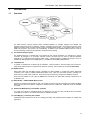
The RDS Precision Farming System offers unrivalled flexibility for enabling mapping and variable rate
treatment with a wide range of combines, sprayers, spreaders and seed drills. The heart of the system is the
PS8000 controller which can either directly control a retrofitted RDS system, or can interface with a range of
OEM control systems. (see section 6 for compatibility). In addition to the standard PS8000 head unit, some or
all of the following component are required to enable Precision farming:
(i) Pro-Series Software Program
The PS8000 head unit is supplied with core software for the primary application, for example as a sprayer
controller. By plugging in a secondary software module, the head unit can then be switched between
applications, e.g yield monitoring/mapping (RDS Ceres), route/soil mapping, variable-rate sprayer control or
variable-rate belt spreader control (RDS Apollo), or variable-rate seed drilling (RDS Artemis).
(ii) Installation kits
A number of standard kits containing all the hardware - sensors/actuators, electrical wiring and connectors,
adapt the specified machine or implement for Precision Farming. Also includes the necessary Data Leads.
(iii) DPGS receiver
RDS supply either the GBX MAX receiver compatible for either satellite or coastal base station differential
reception, or the Jupiter 5 (satellite differential reception only). Both are 12-channel receivers, enabling submetre accuracy (under ideal conditions). Both receiver types are factory-configured for EGNOS reception.
Any receiver is suitable if it can output an NMEA 0183 : RTCM SC-104, GGA data message at 4800 baud, via
an RS232-C port.
(iv) Data Module +16MB PCMCIA Memory Card
Required to upload and download PF data. The module accepts an industry standard pre-formatted PCMCIA
Flash memory card The module is supplied as standard with one 16MB card. Additional cards are available
from RDS.
(v) External PCMCIA Memory Card Reader (optional)
You need one of these for transferring data to a desktop PC if it does not have a PCMCIA slot as standard,
unlike laptop computers. An external card reader is available from RDS.
(vi) Yield Mapping / Treatment plan software
Suitable third-party software for the PC for creating yield maps and preparing treatment plans for variable rate
application.
5
PRO-SERIES - GPS, DATA LOGGING AND TRANSFER
1.2
Head Unit - communication ports
Here is what you need to check concerning connection to and configuration of the RS232 serial ports on the
head unit. For more detailed information on individual hardware options, please refer to the appropriate subsection of the manual.
(i) For a Precision Farming application, the software in the head unit must have the PF (Precision Farming)
driver version 2.034 or higher.
The driver version appears at the bottom of the opening screen when the unit is switched on. The PF driver is
integral to the Apollo core software and enables all the data logging and variable rate treatment functions in
the PS Apollo. Except for the Ceres 8000 core software, these functions are common between the various
software modules currently available, e.g.
PS515-xxx - PS Apollo Sprayer Controller
PS516-xxx - PS Apollo Belt Spreader Controller
PS517-xxx - PS Apollo Mapping Module
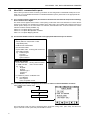
(ii) The external hardware must be connected to the appropriate RS232 serial port as follows:Top Port options
• Printer (RDS ICP 100/ICP 200 or other
compatible printer)
• PCMCIA Data Card Module
• PC Download Cable
• System ERIS cable - receiving VRT instructions
from OEM controller
e.g. Fieldstar Type 1
Soyl Opti
Agrocom ACT
Hydro-N Sensor
Bottom Port options
• System ERIS cable* - sending VRT instructions
to OEM controller. *Also connects DGPS.
e.g. Vicon
Bogballe
Amatron
Fieldstar Type 1
LH5000 v4
RAVEN
• or: DGPS-only Cable - S/CB/268-1-045
e.g. CSI GBX Max
RDS Jupiter 5
Other compatible receiver
(iii) The RS232 ports must be configured in the software to suit the connected hardware as follows:Press
to select SETUP, then,
5. GENERAL PF SETUP
6. PORTS SETUP
The Ports Setup screen can also be accessed via the Technician Config menu (PIN=1234). Use the arrow
keys to select the correct option and press ENTER to confirm.
6
PRO-SERIES - GPS, DATA LOGGING AND TRANSFER
2.
DGPS Receiver Setup
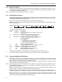
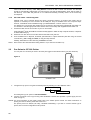
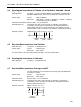
Connect the DGPS MAX (see 2.4) or Jupiter 5 receiver (see 2.5) to the bottom RS232 port using the ProJupiter lead S/CB/268-1-045.
DB-9 Male - to Pro-Series
Pin 1 - Ground (Blue)
Pin 4 - RXD (Green)
DB-9 Male - to Receiver
Pin 5 - Ground
Pin 2 - RXD
Figure 1: Pro-Series to Jupiter Lead
NOTE: If sending VRT instructions to a third-party controller (System ERIS), the bottom port shares DGPS data in and
VRT data out via a custom lead. Refer to section 6 for further information on System ERIS applications.
2.1
Receiver requirement
Any other compatible receiver may also be used. It must be configurable to the following specification:Connection:-
RS232-C interface (DB-9 Female Connector) with the following pin outs.
Cable from receiver
NOTE: The pin 3 function (NMEA/RTCM input to receiver) is not utilised with the Pro-Series.
Data Protocol:-
2.2
Data format
Baud rate
Data output rate
Data Bits
Stop Bits
Parity
Flow Control
NMEA 0183 / RTCM-104, GGA, VTG and ZDA messages
4800 /9600
1Hz / 5Hz
8
1
None
Off
NMEA 0183 Data Messages
GPS data is 'packaged' into a number of standard message sentences each with a data subset suited for
specific communication requirements. The most common message sentences are listed below.
Message sentence
GPGGA
GPGLL
GPGSA
GPGSV
GPRMC
GPVTG
GPZDA
Max. Rate
5 Hz
5 Hz
1 Hz
1 Hz
5 Hz
5 Hz
5 Hz
Contents
GPS Fix Data
Geographic Position - Latitude / Longitude
GPS DOP (Dilution of Precision) and Active Satellites
GPS Satellites in view
Recommended Minimum Specific GPS Data
Track Made Good and Ground Speed
Time and Date
2.2.1 Message Rate settings
Although the Pro-Series only requires a 1Hz input, it will continue to operate satisfactorily with a 5Hz input. No
configuration is required.
For certain applications e.g when using the Marker™ guidance system, the higher rate is essential to get good
guidance performance, and therefore it is recommended to always configure the GPS receiver for 5Hz output.
7
PRO-SERIES - GPS, DATA LOGGING AND TRANSFER
2.2.2 Baud rate settings
By default, the GPS receiver and the Pro-Series are factory-configured to 4800 baud rate. However, you can
re-configure the Pro-Series for 9600 baud rate for the GPS receiver input, in which case the receiver must also
be configured to 9600 baud (section 2.6).
NOTE: Set the GPS receiver to 9600 baud for Marker™ operation.
2.2.3 GGA Message Sentence
The GGA message sentence is normally the only message sentence required by the Pro-Series, except for the
Ceres 8000 or Mapping Module software, where you have the option to configure the instrument to calculate
forward speed from the VTG message sentence.
Marker™also utilises the VTG message sentence for forward speed measurement.
Broken down into its components, ('fields' divided by commas or 'comma delimited'), a typical GGA message
takes the following form:-
$GPGGA,125838, 5141.7196, N, 00213.3253, W, 1, 04, 0.98, -342.6, M, 48.5, M,
Field #
1
2
3
4
5
6
7
8
9
10
11
,*48
12 13 14
The meaning of each field is as follows:Field #
1
2
3
4
5
6
7
8
9,10
11,12
13
14
Syntax
hhmmss.ss
Description
UTC time (=GMT) in hours, minutes, seconds of the
GPS position
ddmm.mmmmm Latitude in degrees, minutes, decimal minutes
s
s = N or s = S for North or South latitude
ddmm.mmmmm Longitude in degrees, minutes, decimal minutes
s
s = E or s = W for East or West longitude
n
GPS quality indicator,
0 = no position
1 = undifferentially corrected position
2 = differentially corrected position
9 = position computed using almanac
qq
number of satellites received
pp.p
Horizontal Dilution Of Precision (HDOP)* = 0.0 to 9.9
saaaa.aa,M Antenna altitude and units, M = metres
±xxxx.xx
Geodial Separation*, M = metres
sss
Age of Differential correction in seconds
aaa
Differential Reference Station ID
*
**
Resulting from the geometry of visible satellites i.e. their relative position over the arc of sky.
The difference between Mean Sea Level (MSL) and the WGS-84 geo-datum (the Earth Ellipsoid).
2.3
General Installation Guidelines
•
The following sections give an overview which should in most cases, be sufficient to successfully install the
DGPS receiver. These instructions are extracted from the CSI User manual supplied with the receiver kit. Please
refer to section 2 of the CSI User manual for further information.
Mount the antenna in the location for which you desire a position e.g. along the centre line of the vehicle and as
close as possible over the working interface.
NOTE: As this may well be impractical to achieve, the Pro-Series can be programmed via the PF SETUP menu with
GPS ANTENNA OFFSETS to compensate for the difference in position of the antenna from the cutter bar,
spray boom etc (see section 4.4).
• Mount the antenna to give an unobstructed hemisphere of sky. This will ensure that GPS satellites are not
masked by parts of the vehicle, potentially reducing system performance.
8
•
Wherever possible, avoid drilling holes in the roof to avoid both water ingress and possibly wiring / air
conditioning equipment etc. If drilling is unavoidable, use silicone sealant around fixing and cable entry points.
•
Mount the antenna as far as possible from any equipment that can cause Electromagnetic Interference (EMI)
including DC motors (e.g. air conditioner), alternator, solenoids, CB radio, power cables, display units, or other
electronics. Excessive EMI will degrade system performance.
PRO-SERIES - GPS, DATA LOGGING AND TRANSFER
•
2.4
TIP: To detect possibly troublesome interference, tune a LW band portable radio off-station. With the aerial laid
flat you can then (hopefully) pick up the direction and source of the interference from the increase in
noise. The antenna can then be repositioned or if necessary, the source of the interference suppressed. If
need be, contact RDS for further advice on suppression methods.
Secure the antenna cable close to the antenna mounting (using cable ties) so that in the event the antenna is
knocked off it's magnetic mounting, it will be restrained and minimise the possibility of further damage.
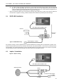
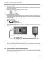
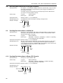
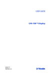
DGPS MAX Installation
Antenna
Pro-Jupiter Lead S/CB/268-1-045
Connect to
chassis
Figure 2: DGPS MAX wiring
Power Supply 9 - 48V DC
The magnet mounting comes supplied with an optional self-adhesive mounting plate for attachment to plastic roofs.
Run the antenna cable across the roof and down into the cab. The power lead has a 1.5A in-line fuse, which should be
left accessible. For the best performance connect the GND terminal to the vehicle chassis. The receiver incorporates
reverse polarity protection to prevent damage if the power leads are accidentally reversed.
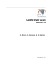
2.5
Jupiter 5 Installation
Figure 3: Jupiter 5 wiring
Pro-Jupiter Lead S/CB/268-1-045
Antenna/Receiver
Port A
Port B
10 -32V DC Power Supply
+V (Red)
0V (Black)
1A Fuse
9
PRO-SERIES - GPS, DATA LOGGING AND TRANSFER
NOTE: Either port A or B can be connected, however, port A must be used for a firmware update of the receiver (ref.
section 2.6).
The Jupiter 5 may be mounted in 3 ways :• Magnetic mounting base (pre-installed). Suitable for any steel surface.
•
Surface-mounted using screws. Remove the screw caps on the antenna. Drill 3/16" dia holes and fasten
using the screws provided. Replace the screw caps. Do not overtighten the screws!.
•
Pole mounted. This option will minimise the possibility of radio electrical interference. Thread the 5/8" - 11
UNC threaded mount onto a suitable threaded pole. Hand tighten only! Place the antenna (with magnetic
mount) onto the threaded mount.
With each mounting method, ensure there is sufficient slack on the cable at the antenna end, so that minimal
strain is applied to the cable entry point.
The power lead has a 1 Amp in-line fuse, which should be left accessible. Once the power lead is connected
the receiver will be immediately powered. The receiver incorporates reverse-polarity protection to prevent
damage if the power leads are accidentally reversed.
The receiver will proceed automatically through a startup sequence. Given satisfactory signal reception it
should normally provide position within 1 minute. A full 3-D Diff position may take longer.
Please refer to section 4 of the CSI Seres User Manual if you require more in-depth information.
2.6
Jupiter 5 / DGPS Max Configuration
The following setup assumes that the differential source is EGNOS (the European Geostationary Overlay
System). If you intend using beacon reception or the Omnistar service for differential correction, then please
call RDS for further advice, as this manual does not cover these options.
Both receiver types are factory-configured for EGNOS reception, and the data protocol settings are as in
section 2.1 to suit the Pro-Series.
Prior to configuration you should have installed on your PC the following files:TERMINAL.EXE
SERESRDS.TRM
SLXMON1.EXE
The programme used to send commands to configure the receiver.
The file containing the custom settings required for an RDS installation.
The programme used for real-time monitoring of the receiver output for diagnostic
purposes.
If you don't already have these files then they can be emailed (or sent on CD-ROM) on request.
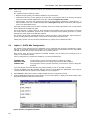
1.
Connect the RS232 serial cable supplied with your receiver, from the MAIN port (DGPS Max) or the 9-way 'D'
connector labelled "Port A" (Jupiter 5) to the COM port on your laptop/PC.
2.
Start TERMINAL1.EXE. This provides a simple terminal window to configure the receiver.
3.
Open file SERESRDS.TRM in the terminal window, (use File, then Open), to display some buttons which when
pressed will upload commands into the receiver.
Figure4: Receiver configuration software
10
PRO-SERIES - GPS, DATA LOGGING AND TRANSFER
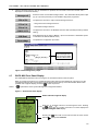
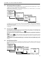
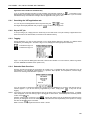
4.
Click the following buttons in turn (as each button is pressed, the command is sent to the receiver and is
displayed in the Terminal window):Switches off the normal GPS message stream. Also deactivates binary data output
(fig. 5) if you have previously run the 'SLXMon' diagnostic programme.
Configures the receiver to output a GGA message sentence...
...along with a VTG message sentence...
...and a ZDA message sentence.
Configures the receiver to use EGNOS correction data (normally the factory-default
setting).
Sets 9600 baud rate for input to Marker™ (and for Pro-Series if a "GPS 9600" option
is selected in the PORTS SETUP menu).
Completes the configuration procedure.
Indicates Binary Output
Press 'Messages Off' to
stop, then press GGA,
VTG and ZDA buttons
Figure 5: Deactivating Binary output
2.7
DGPS MAX Front Panel Display
The DGPS MAX is switched on and off using the On-Off switch located on the rear panel.
When you switch the receiver on, it will sequence through a startup screen followed by a prompt to use the
Configuration Wizard. After 3 seconds the receiver will proceed to the top of the GPS Position Status menu
(Latitude and Longitude display) unless the
button is pressed.
NOTE: If
is pressed the menu system will begin the Configuration Wizard.
Figure 6 : GPS Position Status display
Default Latitude/Longitude display
Press the
and
buttons to scroll through the menu. Pressing
the
button with any of these menu items on screen displays the
Signal Tracking Bar Chart display.
Pressing the
button with a menu item that has the menu access
indicator
displays that submenu.
11
PRO-SERIES - GPS, DATA LOGGING AND TRANSFER
Pressing the
button with a menu item displayed that does not have the menu access indicator
to the Signal Tracking Bar Chart display.
, switches
The bar chart consists of two main parts, providing an indication of the GPS satellite signal quality per receiver
channel 1 to 10, and the signal quality of the differential source (channel 11/12). For each bar, the higher the
bar, the greater the signal quality.
GPS Satellite signal reception quality (channels 1-10)
Differential Correction signal quality (channels 11/12)
Differential Source Indicator:GPS icon
WAAS (Wide Area Augmentation System) input
(Default = EGNOS)
Omnistar input
Beacon input (1st bar = signal strength, 2nd bar = Signal to Noise
Ratio)
External RTCM input (no associated bars)
Autonomous mode (no associated bars)
Figure 7 : Signal Tracking Bar Chart display
Please refer to section 5 of the CSI User Manual if you require more in-depth information.
2.8
GPS Diagnostics
The following diagnostic tools are not specifically for the DGPS MAX and Jupiter receivers, and are useful for
diagnosing the output from any GPS receiver.
2.8.1 'SLXMon' software
'SLXMon' is an in-depth diagnostic tool used to monitor receiver performance. SLXMon displays among other
parameters, realtime satellite information and signal quality. It allows you to view diagnostic information from
the receiver, send commands (although TERMINAL.EXE is recommended for this), view NMEA and RTCM
messages, and also has other functions.
Connecting to SLXMon
1.
Connect the RS232 serial cable supplied with your receiver, from the MAIN port (DGPS Max) or the 9-way 'D'
connector labelled "Port A" (Jupiter 5) to the COM port on your laptop/PC, and power the receiver on.
2.
Start SLXMon by double-clicking on the file SLXMON1.EXE and click 'File > Connect'. Select 9600 baud rate
and the COM port to which the receiver is connected and click 'OK'.
Now watch the status bar at the bottom of the SLXMon window. If you are properly connected, the 'Not
Connected' message is replaced with a 'Fix Status' message, and the current COM port number and baud
rate replaces the 'Not Open' message.
NOTE: When you connect the receiver to SLXMon the software instructs the receiver to output binary data from the
port connected. SLXMon uses this binary format to receive and display data. However, you must deactivate
binary output before reconnecting the receiver on to your own equipment. This is best done from
TERMINAL.EXE. (section 2.6).
12
PRO-SERIES - GPS, DATA LOGGING AND TRANSFER
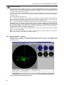
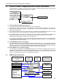
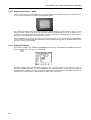
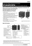
Diagnostic Windows
Once communication is established, the channel data will then start to populate the window.
Angle above
horizon
Direction
(0 = North)
Satellite Lock Status
Signal to
Noise
Ratio
GPS Satellites
EGNOS
Satellites
Figure 8 : 'SLXMon' Diagnostic software
The buttons along the top of the SLXMon window are used to open a number of different diagnostic windows.
The commonly useful ones are:'View GPS Solution'
Check these fields:
NavMode - This field reports the Fix Status and can show any of the following messages:
No Fix
2-D NO DIFF
3-D NO DIFF
2-D DIFF
3-D DIFF
If you see any of these fields except 'No Fix' then you are receiving GPS data. The receiver needs to find and
use at least 4 satellites to receive a 3-D position. Ideally, you should see 3-D DIFF, which means you have 3-D
GPS and a differential solution fix.
No. Used(mask) - This field reports the number of GPS satellites being used by the receiver to acquire a
position (ignore mask value). This number must be 4 or more to receive 3-D GPS. If the number is less than 4
you should check for obstructions near the antenna. Check your antenna and antenna cable if the number is
0. A good value would be in the range 5 - 12 satellites used.
NOTE: When your receiver is receiving GPS information from the satellites, the fields Lat, Lon, Date and Time will all
report current information. If these fields remain at 0, then you likely have an antenna problem.
AgeDiff - This the age of differential and should remain somewhere between 1 and 20 (the lower the better). If
it is 0, then you do not have Differential. If it counts to the Diff Age-Timeout (3600 default), then you will lose
your differential lock.
13
PRO-SERIES - GPS, DATA LOGGING AND TRANSFER
'View of Channel Data'
Each channel represents a satellite. Channels 1 to 10 are the GPS satellites. Their position in the hemisphere
is indicated by elevation and azimuth (the compass heading). The higher the elevation, the stronger the signal
is likely to be as it will be less affected by atmospheric conditions or line of site obstructions e.g. the
surrounding topography, buildings trees etc.
Channels 11 and 12 are the two geostationary satellites broadcasting EGNOS correction data. Depending on
your geographic location, either one will be visible. No values for any given channel indicate that a satellite is
not in line of sight.
The important fields in this window are:
CH - The channel numbers are colour coded to show whether or not a specific satellite is being used in the
solution (has Lock). The channel number will turn Green when the receiver has a full lock on the satellite. The
number of satellites with green numbers is the same as the number of satellites used.
ELV - This is the elevation of the satellite in degrees above the horizon. By default, the receiver will ignore
any satellite lower than 5 degrees above the horizon. This can be changed by setting the Elevation Mask with
$JMASK command. The receiver is more precise when it has more than 4 satellites widely spread across the
sky at various elevations. This is called good constellation geometry and is indicated by the HDOP/VDOP
(Horizontal/Vertical Dilution of Precision) values in the 'View GPS Solution' window. A lower DOP indicates a
stronger potential for better accuracy than a higher DOP.
LOCK - Use this column when you cannot distinguish the colours of the channel numbers. When a satellite
has lock, this value will be CXBF.
SNR - The Signal to Noise Ratio of a satellite is used to illustrate the relative quality of the information
packets being received. A good SNR value would be above 12.
2.8.2 Ashtech Evaluate™ software
Ashtech Evaluate™ generates a real-time graphical display of position error and other computed GPS
information, and is a useful tool to indicate the relative accuracy of your receiver. This program can be
emailed on request.
Figure 9 : 'Ashtech Evaluate' Diagnostic software
14
PRO-SERIES - GPS, DATA LOGGING AND TRANSFER
3
Data Logging and Transfer - Hardware Setup
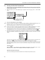
3.1
Data Card Module
There are a number of options available for logging and transferring data between the Pro-Series and the PC.
The Data Module accepts a PCMCIA Flash Card to store data generated from harvesting, soil sampling,
variable-rate treatment, or upload data e.g treatment plans or navigation data for soil sampling. A maximum of
16Mb of data can be stored on the card (typically enough for about 600 hectares).
Figure 10
S/CB/268-1-046
Data Module
1.
Configure the top port to recognize the Data Module by selecting from the calibration menu,
5. General PF Setup
6. Ports Setup
and setting the top port option to "RDS PF MODULE" .
2.
Connect the module to the top port. The module is powered from the head unit. Insert the card as shown in
figure 11 and the green LED will come on indicating that the head unit has detected the card. The red LED
indicates when data is being written to or read from the card.
NOTE: Do not remove the card while the red LED is on as this may cause an irretrievable loss of data on the
card.
Figure 11
Green LED ON
= Card recognized
Red LED ON
= Data read/write
3.1.1 Card Compatibility and Formatting
The PCMCIA data card conforms to the ATA interface standard. The maximum formatted capacity is 15.2 Mb
regardless if it is a higher capacity card. The head unit will not recognize a card formatted larger than 16 Mb.
Cards supplied by RDS are pre-formatted ready for use.
Earlier compatibility issues with externally sourced cards have largely been resolved, therefore if you are using
a card not supplied by RDS, then format it in Windows Explorer i.e. if it is Drive D:,
1.
Right-click on "Removable Disk (D:) and select "Format".
2.
From the "Format" window, select the "Full" checkbox for the format type, enter a volume description if desired,
and then press "Start".
15
PRO-SERIES - GPS, DATA LOGGING AND TRANSFER
Cards must have a directory called "Rds_data.xxx" in which all data is stored and retrieved. This directory
should be automatically created when you first insert the card into the Data Module. All PF data is written to
this directory. If the folder "Rds_data.xxx" is not created automatically, manually create it in the normal way
from Explorer.
3.1.2
PC Card reader - transferring data
PCMCIA cards can be inserted directly into laptop computers however, an external card reader may be
required for a desktop PC and connects via the USB port. They are available from most computer shops
however, a suitable kit is also available through your RDS distributor:- Part No. S/AC/311-1-005.
For desktop PC's connect the card reader to the PC according to the instructions supplied with the reader unit.
You will have to load the appropriate driver software found on the setup disk supplied with the reader unit.
1.
Transfer the flash card to the card slot on your PC card reader.
Under Windows® 95/98, the PCMCIA card will normally appear in either the 'My Computer' window, or Explorer
as 'Removable Disk [D:]'.
2.
Double-click on this drive to access the card and the folder "Rds_data.xxx".
3.
From the File menu in Explorer, download yield data files or upload treatment plan files using the normal
commands e.g. Cut or Copy and Paste, or 'drag and drop' the files.
Similarly, delete files from the card using the Delete command.
NOTE: Never remove the card while data is being written to it (i.e. when the red LED is on).
3.2
Pro-Series to ICP 200 Printer
You can print out a summary for each or all of the jobs logged to the internal memory (75 jobs maximum).
Figure 12
In-Cab Printer
S/CB/268-1-049
1.
Configure the top port to recognize the ICP200 printer by selecting from the calibration menu,
5. General PF Setup
6. Ports Setup
and setting the top port option to "ICP 200 PRINTER" .
2.
Connect the printer to the top port using cable S/CB/268-1-049 that also provides a power supply from the
head unit (fig 12).
NOTES: For more information on the printer, please refer to the ICP200 printer manual. For further information on
printing from the Pro-Series, please see section 5.5.5
The printer protocol is 4800,8,1,No Parity, Hardware handshaking. If you wish to connect another type of
printer, then it must be configurable to this protocol.
16
PRO-SERIES - GPS, DATA LOGGING AND TRANSFER
3.3
Pro-Series to PC Link Cable
Any Pro-Series instrument equipped with data logging and download facility can transmit data to a PC or
laptop running Windows 95 or 98 and a terminal emulator programme such as Windows HyperTerminal or the
RDS 'Data Capture' utility.
1.
Configure the top port (Apollo setup) by selecting from the calibration menu,
5. General PF Setup
6. Ports Setup
and setting the top port option to "PC DOWNLOAD" .
NOTE:
Ceres 8000 setup is different to Apollo setup. Please refer to the Ceres 8000 user manual.
Connect the instrument to the serial port of the laptop/PC using a 'Pro-Series to PC Upload' cable
S/CB/268-1-032. N.B. some laptops do not have RS232 ports but only have USB ports. In this case you will
require a USB - Serial adapter.
3.3.1 Creating a HyperTerminal Shortcut on Windows Desktop
1.
From the desktop, click on an empty area of the desktop background with the right hand mouse button. A
message box will appear.
2.
Click on 'New'
3.
Click on 'Browse' then select C:\Start Menu\Programs\Accessories\Communications, and select
'HyperTerminal'. If you cannot locate it, refer to section 3.3.2 .
4.
Click ''Open' then 'Next' and change the name for the programme if desired e.g. "RDS Download",
5.
Click on 'Finish'. The HyperTerminal folder is now on the Desktop.
'Shortcut'. The 'Create Shortcut' box will appear.
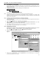
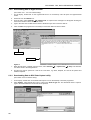
3.3.2 Enabling HyperTerminal
Hyperterminal is a standard accessory supplied with Windows 95 and Windows 98, however it may not have
been enabled when Windows was setup. If Hyperterminal is not available in the Accessories folder :'Settings'
'Control Panel'
1.
Click on 'Start'
2.
Select the “Windows Setup” tab on the top tab list
'Add/Remove Programmes'
Figure 14
1
2
3
4
5
3.
Double click on “Communications”, check the “Hyperterminal “ box and click 'OK'. (fig.14). You may require
your Windows installation disc to install it.
17
PRO-SERIES - GPS, DATA LOGGING AND TRANSFER
3.3.3 Setting up HyperTerminal
1.
From the Windows 95/98 desktop, double-click on the
shortcut to open the HyperTerminal folder (if you have
not already created a shortcut, see section 3.3.1), and
then double-click on the 'HyperTerminal.exe' icon.
2.
A 'Connections Description' box will appear. Enter a
name, e.g. RDS , select an icon and click 'OK'.
3.
A 'Connect To' box will appear. In the 'Connect Using'
window, select 'Direct to Com 1' or 'Direct to Com 2',
depending on which port you will be using. Generally
on a laptop it will be Com 1. On a PC it will be Com 2
(or Com 3).
4.
Click 'OK'.
5.
A 'Properties' box will appear for the selected port.
Set
Bits per second:
Data bits:
Parity:
Stop Bits:
Flow Control:
Figure 15
Saved Configuration
for Pro-Series
4800
8
None
1
Xon/Xoff
and click 'OK'.
HyperTerminal should now be in communication with
the instrument. If not, a common reason is that the
wrong COM port has been specified in the 'Connect
Using' window' (On a PC, COM 1 is commonly used for
the mouse).
6.
When you exit HyperTerminal, you are prompted to
save a configuration file with the name as previously
entered in the 'Connections Description' window. Click
'Yes' and an 'RDS.ht' icon will appear in the
'HyperTerminal' folder (fig.15).
3.3.4 Setting up RDS 'Data Capture' Utility
This utility programme is available to download from the RDS website at <www.rdstec.com>. RDS Data
Capture is a simple terminal programme that enables data logged and stored on an RDS Pro-Series
instrument to be downloaded to a PC via RS232 serial port and saved either as formatted text (*.txt) or as csv
(*.csv) data. These files can then be opened in a word processor or in a spreadsheet (ex. MS Excel) for
printing or analysis.
To install onto your hard drive you must have Winzip installed.
18
1.
Simply double-click on the file 'Data Capture Install.zip' in the C:\TEMP directory to view the contents of the zip
file.
2.
Double-click on 'Setup.exe to run the install program. An icon is created on the desktop.
3.
Double-click the icon to start the programme then click 'Set-Up' to configure the COM port setting, then click
'OK'.
PRO-SERIES - GPS, DATA LOGGING AND TRANSFER
3.4
Pro-Series to PDA
It is not feasible for RDS to give specific instructions for every PDA model due to the constant development of
new hardware and software. In general however, whichever PDA and the operating system it uses, to link to
the Pro-Series simply requires,
(i)
a terminal emulation programme installed with the protocol settings;
Baud:
Data bits:
Parity:
Stop Bits:
Flow Control:
4800
8
None
1
Xon/Xoff
(ii) a RS232 9-way 'D' serial port connection.
The PDA docking station may already have a 9-way 'D' for connection to a laptop or PC in which case it can
connect directly to the RDS Pro-Series-PDA cable, otherwise you will need to purchase an additional RS232
Serial Adaptor lead to link between the RDS cable and the PDA (normally available as a standard accessory
from your PDA dealer).
1.
Configure the top port by selecting from the calibration menu,
5. General PF Setup
6. Ports Setup
and setting the top port option to "PC DOWNLOAD" .
2.
Connect the instrument to the docking station serial port or serial adaptor lead of the PDA using a 'Pro-Series
to PDA' cable S/CB/268-1-081 (fig. 18).
Figure 18
S/CB/268-1-081
Serial Adaptor Lead (available from your PDA dealer)
3.4.1 Terminal emulation for Palm OS operating system
Palm OS does not ship with a terminal emulator, however you can choose to download a suitable third-party
emulator programme via the Internet.
One such programme is Online, a VT100 terminal emulator and Telnet client for Palm OS organizers with
Palm OS 3.0 or later. It can be downloaded from Mark/Space (www.markspace.com).
3.4.2 Terminal emulation for Windows CE operating system
Windows CE Handheld PCs ship with a very weak terminal emulator. The Palm-size PC and Pocket PCs do
not ship with a terminal emulator application. As with Palm OS, you are advised to download a suitable third
party emulator programme via the Internet. There are plenty of forums where the latest advice on installation
and configuration is freely available.
19
PRO-SERIES - GPS, DATA LOGGING AND TRANSFER
4.
Logging / P.F. Functions - Software Setup for Apollo Instruments
Reference: PF Driver Version 2.036
It is assumed that the hardware e.g. Data module, GPS, Third party controller etc, has already been configured
as per sections 2, 3 and 6 in this manual.
Before commencing PF operation, you should check and adjust if necessary any of the following parameters
to suit your particular application. The PF settings are found under '5. General PF Setup' in the calibration
menu.
4.1
Logging Interval
It is recommended that you use the default setting of 5 seconds. This should be adequate for variable-rate
treatment with a typical 24-metre sprayer, and yield mapping. To ensure correct application from treatment
plans with a smaller cell size may therefore, require a shorter logging interval to be set.
Decreasing the logging interval may affect the responsiveness of the control system and generate very large
log files, therefore reducing the number of jobs that can be accommodated on the PCMCIA card. An exception
is when you are boundary mapping (where less data is being generated), you can reduce the logging interval
to get better definition of the field boundary.
Simply enter the interval value and press the ENTER key to confirm.
NOTE: Although the option to select the logging interval by distance is available, it no longer recommended you do
so.
4.2
Tag Names
Applies to yield mapping only.
While dynamic logging is in progress the operator can switch on or off any of up to 8 'tags' which effectively
place markers on subsequent yield maps to denote particular features such as weed patches etc. Each tag
can be named (up to 20 characters) to denote its meaning on the yield map. The first 4 tag names are factory
preset as Black Grass, Wild Oats, Cleavers and Thistles.
To change a name, first position the menu pointer against a tag. Using the RIGHT ARROW key, move the
screen cursor across to the tag name and enter the data via the alpha-numeric keypad.
Press the ENTER key to confirm the data entry then repeat the procedure as required for further tag names.
20
PRO-SERIES - GPS, DATA LOGGING AND TRANSFER
4.3
Edit Function Names and Values
The default settings can be re-programmed for any of the extended data functions (default names = "FUNC 1"
- "FUNC 12") e.g. Crop, Contractor, Driver, Product applied etc.
Further to this, for each function 1 - 12, you can then programme up to 6 different values e.g. Crop variety,
Contractor name, Driver name, Product name etc.
etc...
To change a name, first select the function number using the ENTER key. Using the RIGHT ARROW key,
move the screen cursor across to the function name and enter the data (up to 20 alpha-numeric characters)
via the alpha-numeric keypad.
To enter a value, move the cursor down to the first line and enter the data. You can enter up to 6 lines each of
10 characters.
4.3.1
Clear Store function
In normal operation, each time you start a job you are prompted to select a value for each extended function
that is enabled on the 'Job Startup' page. The 'Clear Store' function control whether or not the default value
prompt is the one selected for the previous job.
If a function on the 'Function Names/Values' page is set to
(Clear Store), no default value will appear on
the 'Job Startup' page or be logged for that function, unless the operator manually selects a value via the
key.
If a function is set to
(Store), then when a new job is started, the value set for the previous job will
appear on the 'Job Startup' page. It then becomes the responsibility of the operator to change the value via the
key if so desired.
In nornal operation, it is less likely that mistakes will occur in setting the value for an extended function if 'Clear
Store' is selected on the 'Function Names/Values' page. For this reason it is the factory default setting for all 12
functions.
4.4
Set GPS Antenna Offset
The "Antenna Offset" allows you to compensate for the difference in position between the GPS antenna and
the feature being logged, centre of the spray boom/cutter bar/coulter bar, or the centre point of a spreading
pattern.
ROUTE LOGGING
SOIL SAMPLING
PLAN CHANNEL 1
PLAN CHANNEL 2
PLAN CHANNEL 3
PLAN CHANNEL 4
21
PRO-SERIES - GPS, DATA LOGGING AND TRANSFER
You can have 6 separate configurations for,
ROUTE LOGGING
SOIL SAMPLING
PLAN CHANNEL 1
PLAN CHANNEL 2
PLAN CHANNEL 3
PLAN CHANNEL 4
(Default for all configurations = No offset).
For example, you might need a 2-metre side offset for boundary mapping from a quad bike, so you would edit
the 'ROUTE LOGGING' configuration.
Say for example, that you were going to use a front-mounted spreader (that was controlled via channel 1) and
a rear-mounted spreader (that was controlled via channel 2) together, you would set the offsets for each. You
would edit the 'PLAN CHANNEL 1' configuration for the front-mounted implement, and the 'PLAN CHANNEL 2'
configuration for the rear-mounted implement.
Select the configuration that you wish to edit and press the EDIT key.
Use the arrow keys to offset the antenna position in 0.5 metre increments, and press the ENTER key to
confirm.
4.5
GPS Home Location
This page displays your current position. Press the ENTER key to store this position as the "home location"
e.g. the farm.
The 'RADIUS' setting enables the instrument to filter out spurious positional data, which if logged as normal
could cause problems when importing the data into mapping and treatment planning software. Any position
received outside the operating radius is assumed to be corrupt data and will be ignored.
Set the radius to an appropriate figure e.g. to encompass the total farmed area.
If you subsequently move outside the radius circling the home location, the instrument will automatically reset
the "home location" to the current position ONLY IF it receives 10 consecutive, full differential GPS signals.
At any time, you can press the ENTER key while on this page, to manually set the home location to your
current position.
22
PRO-SERIES - GPS, DATA LOGGING AND TRANSFER
5.
The LOG Screen - Logging Options for Apollo Instruments
The Pro-Series has a separate LOG screen. Data is logged to internal (summary) memory and/or external
(dynamic) memory depending on the logging option selected.
LOGGING OPTIONS
(i) APPLY FROM PLAN (Variable-Rate Treatment)
The variable rate instruction is implemented in one of the following setups,
(a) the Pro-Series receives the rate from a treatment plan on the RDS Data Card Module and controls the
application via the RDS control system. A full application record of the actual application is generated and
saved on the Data Module.
(b) the Pro-Series receives the rate from a treatment plan on the RDS Data Card Module and sends it to a third
party controller, which controls the application via the OEM control system (System ERIS).
(c) the Pro-Series receives the rate from a third-party controller and controls the application via the RDS control
system (System ERIS). The Pro-Series can send back the actual application rate to the other controller
All setups allow the operator to commence a full VRT application.
For (a) and (b) a full application record of the actual application is generated and saved on the Data Module.
The associated work record file can be viewed in the mapping/treatment plan software. Job summary data (iii)
is also appended to the work record file.
(ii) LOG TREATMENT (Dynamic Data Logging)
A full application record is generated, logging rate and other parameters (e.g. "tags") in real time, attributing
this data to a specific location. The associated "Dynamic Logging" file is viewed in the mapping/treatment plan
software. A large amount of data is generated by dynamic logging and therefore must be saved onto an RDS
Data Card Module. Job summary data (iii) is also appended to the dynamic logging file.
(iii) LOG SUMMARY ONLY (Field Data Logging)
For simple farm record keeping and traceability purposes, you can record a summary of each job or work
session in the internal memory, and subsequently download directly to a PC, to a Data Module, or print to an
RDS ICP200 In-Cab Printer. The amount of summary data for each job is small, and is saved in the internal
memory. The instrument can store up to 75 individual job summaries.
5.1
MAIN Screen Information
Indicates data transfer
to/from Data Module in
progress
Time
Tank / Product ID
Forward Speed
Actual application rate
Displays Volume
remaining in tank,
or Flow rate,
or Pressure.
depending on the
function set using the
function key.
Indicates Data
Module
connected
Indicates
GPS
reception
Machine In /Out of
work Indicator
(Area accumulation)
'Performance'
indicator
(above/below target)
Rate from plan
Section width(s)
On/Off Indicator
Override / Return to
Target rate
23
PRO-SERIES - GPS, DATA LOGGING AND TRANSFER
5.2
Running a Variable Rate Treatment plan
1.
Press the LOG key. The screen will display the current logging status, the number of jobs (job summaries)
stored in memory, and the status of the PCMCIA card if found. If the module is not detected the message "NO
MODULE FOUND" is displayed.
2.
Press the START key. The JOB STARTUP page is displayed. Select the logging option "1. APPLY FROM
PLAN".
3.
Key in the 'FARM NUMBER' and 'FIELD NUMBER'.
NOTE: If there is more than one "machine" (i.e. distribution system) enabled, the 'SELECT MACHINE' page is now
displayed. Scroll the cursor to the appropriate machine and press the ENTER key to confirm.
4.
Select the appropriate plan from the list on screen and press the ENTER key to confirm.
NOTE: If there is more than one "machine", the display will then revert to the 'SELECT MACHINE' page. If required,
select another 'machine', press the ENTER key to confirm and then select the appropriate plan.
5.
After selecting plans for each 'machine', press the 'START' key. The "EXTENDED DATA FUNCTIONS" page is
then displayed (section 5.2.4). If you don't wish to programme any extended functions. then press
.
6.
Wait while the work plan file is loaded and a work record file is created on the Data Module. Once the plan is
loaded, the 'RUNNING A PLANNED JOB' page appears, and displays the tag list. See section 5.2.3 about
tagging.
While VRT mode is in operation a flashing satellite symbol
is displayed alongside the Target Rate on the
MAIN screen. The
icon appears animated at the top of the screen while logging is in progress.
The target rate on the MAIN screen now becomes the application rate according to the treatment plan data
(Base rate x Multiplier) and the position in the field. The treatment rectangle size is defined in the treatment
plan software.
Plan Status Display
Press the
key to display the current application rate according to the treatment plan, for each
distribution system in operation. This is displayed as 'Base Rate x Multiplier = App. Rate'
Application Rate without a GPS Signal
If you lose the DGPS signal the treatment rate will revert to the 'Base Rate' specified in the plan.
24
PRO-SERIES - GPS, DATA LOGGING AND TRANSFER
Application Rate outside the Field Boundary
If you go outside the field boundary but are still within the treatment rectangle, a
icon flashes on the
display and the instrument beeps continuously. The application rate reverts to the base rate. If you are outside
the field boundary and treatment rectangle, then the application rate goes to zero.
5.2.1 Overriding the VRT application rate
You can vary the actual application rate at any time using the
The target rate display will flash until you press
keys.
to return to the target rate.
5.2.2 Stop a VRT job
To stop running a job, simply press the 'STOP' key on the LOG screen. The job summary is appended to the
work record file on the data module, and saved to the internal memory.
5.2.3 Tagging
During application, you can log the presence of up to eight different features in the field, e.g. different weed
infestations, pest damage etc. To switch a tag on or off, simply press the appropriate number key.
indicates the tag is off
indicates the tag is on
Tags 1 to 4 are preset for Blackgrass, Wild Oats, Cleavers and Thistles. You can however, edit the tag names
from the 'GENERAL PF SETUP menu (section 4.2).
5.2.4 Extended Data Functions
Dynamic log files and simple job summaries can include up to 12 additional data. All 12 data items can be
user-defined to suit individual requirements e.g. Operator, Wind Speed, Air Temperature, Growth Stage,
Product etc. Entering extended data is optional.
If you do not want to change the default value, simply press the ENTER key to accept it, and then the next 'F'
function appears. If you do not need to programme any of them, simply press
at any time to start
logging.
NOTE: If a function on the 'Function Names/Values' page in the setup menu is set to
(Clear Store), no default
value will appear on the 'Job Startup' page or be logged for that function, unless the operator manually selects
a value via the
key.
Likewise, If that function a function is set to
(Store), then when a new job is started, the value set for the
previous job will appear on the 'Job Startup' page. It then becomes the responsibility of the operator to change
the value via the
key if so desired.
Refer to section 5.2 to programme function names / values.
25
PRO-SERIES - GPS, DATA LOGGING AND TRANSFER
5.2.5 Display vehicle track - "MAP"
From the LOG screen, press the "MAP" key. The screen displays the real time position of the vehicle (the "+"
cursor), and the vehicle track for the last 100 logged data points.
The screen also displays the latitude and longitude in decimal degrees, and the number of points. As the
vehicle proceeds from the start of the job, the screen plots and automatically zooms out to display up to a
maximum of 100 logged data points. Beyond this, as the job progresses, the display pans in the direction of
movement to keep the previous 100 data points on screen.
Press the 'RESET' key to start the plot again from the current position. If you selected the "LOG TREATMENT"
option from the LOG screen page, the track data is saved to a dynamic logging file on the data module, which
can then be viewed in PLOT/PLAN.
5.2.6 Display GPS Status
From either the LOG page, "RUNNING TREATMENT PLAN" page or "RECORDING A DYNAMIC JOB" page,
press the
key to view the current GPS status.
This page displays; Age of Fix Data (when reception is good, the time should not be more than 1 second);
Number of Satellites (minimum of 4 for full differential fix); Differential Status; Latitude and Longitude (in
decimal degrees); Altitude; Heading and Velocity. All this data is read directly from the NMEA GGA and VTG
messages. You can also set the "Home Position" from this screen (section 4.5).
26
PRO-SERIES - GPS, DATA LOGGING AND TRANSFER
5.3
Dynamic Data Logging
An RDS Data Card Module and a GPS receiver must be connected.
When spraying conventionally (i.e. not VRT mode), you have an option to generate a full spray application
record, logging rate and other parameters (e.g. "tags") in real time, attributing this data to a specific location.
The associated "Dynamic Logging" file is saved onto the Data Card Module and can subsequently be viewed
in PLOT/PLAN.
5.3.1 Start recording a Dynamic Job
1.
Press the LOG key.
The screen will display the current logging status, the number of jobs (job summaries) stored in memory, and
the status of the PCMCIA card if found. If the module is not detected the message "NO MODULE FOUND" is
displayed.
2.
Press the START key. The JOB STARTUP page is displayed. Select the logging option "2. LOG TREATMENT".
When prompted, enter the FARM NUMBER and FIELD NUMBER reference. The "EXTENDED DATA
FUNCTIONS" page is then displayed (section 5.2.4). If you don't wish to programme any extended functions.
then press
.
The screen will display "NEGOTIATING FILE STORAGE - JOB NUMBER #" as it creates the dynamic log file on
the data module. Once the plan is loaded, the "RECORDING A DYNAMIC JOB" page appears, and displays
the tag list. You can at any time apply the Tag functions to log features in the field (see section 5.2.3).
While dynamic logging is in progress, the
icon appears animated at the top of the screen.
NOTE: If more than one machine is enabled, the summary job record will include data for each machine.
5.3.2 Stop recording a Dynamic Job
To stop running a job, simply press the "STOP" key on the LOG screen. The job summary is appended to the
dynamic log file on the data module, and saved to the internal memory.
27
PRO-SERIES - GPS, DATA LOGGING AND TRANSFER
5.4
Field Data Logging
For farm record keeping and traceability purposes, you can record a summary of each job or work session in
the internal memory, and subsequently download directly to a PC, to a Data Module, or print to an RDS
ICP200 In-Cab Printer. You can store up to 75 job summaries.
Refer to section 5.5 on downloading or printing data.
5.4.1 Start recording Field Data
1.
Press the LOG key.
The screen will display the current logging status, the number of jobs (job summaries) stored in memory, and
the status of the PCMCIA card if found.
2.
Press the START key. The JOB STARTUP page is displayed. Select the logging option "3. LOG SUMMARY
ONLY".
Memory storage
for field data
When prompted, enter the FARM NUMBER and FIELD NUMBER reference. The "EXTENDED DATA
FUNCTIONS" page is then displayed (section 5.2.4). If you don't wish to programme any extended functions.
then press
.
The "RECORDING A JOB SUMMARY" page appears.
While field data logging is in progress, the
icon appears animated at the top of the screen.
NOTE: The Tag functions are not available in this logging mode.
5.4.2 Stop recording Field Data
To stop running a job, simply press the "STOP" key on the LOG screen. The job summary is saved to the
internal memory.
28
PRO-SERIES - GPS, DATA LOGGING AND TRANSFER
5.5
Review / Reset / Print or Download Summary Data
You can view, delete, print or download one or more jobs. Summary data downloads either in a text format as
a job ticket including space for comments and signature, or in a CSV format.
Depending on your hardware setup (ref. section 3) you can 'print' from the Pro-Series to a printer, to a .txt or
.csv file on the data module, or to a .txt or .csv file saved in either the RDS 'Data Capture' or HyperTerminal
programme on the PC.
It includes all the basic data listed below along with any extended data that was programmed, for each tank
that is enabled.
Job Number
Start Date
Start Time
End Time
Job Duration
Channel No.
Machine ID / Name
Farm No.
Field No.
Product / Crop
Cal Factor
Area
Work Rate
Quantity spread
Quantity loaded
Average Application Rate
Extended Functions F1 to F12 values
Comments*
Operator*
Transmit Time and Date
* Not included in .CSV format
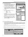
5.5.1 Select Summary Data to Reset or Download
On the Pro-Series, select the job or jobs summaries to download as follows,
Use arrow keys to review /
reset an individual job
Figure 16
Select last job only
or select a range
You have the option to download in Text or CSV format. CSV format is ideal for importing the data into a
spreadsheet. As data is transmitted from the instrument a “progress bar” will be displayed on the Pro-Series.
Now refer to the appropriate section below on capturing the data.
29
PRO-SERIES - GPS, DATA LOGGING AND TRANSFER
5.5.2 Downloading Data to HyperTerminal
(Ref. section 3.3.1 - 3.3.3 for software setup).
1.
On the laptop, double-click on the HyperTerminal icon on the desktop. This will open the HyperTerminal
Folder.
2.
Double-click on the 'RDS.ht' icon.
3.
From the menu, select 'Transfer'
'Capture Text'. A 'Capture Text' message box will appear showing the
name of the text file to which data will be saved.
4.
Type in the name of the folder and the name of the file that you wish to save the data as.
5.
Click on 'Start'. The programme is now ready to receive the data from the Pro-Series.
Text Format
CSV Format
Figure 17
'Capture Text'
7.
When the transfer is complete, from the menu, select 'Transfer'
now been saved to the designated file.
'Stop'. The data has
8.
This file may now be opened as a text file in a text editor, e.g. Word, Notepad, etc and can be printed and
edited as required.
5.5.3 Downloading Data to RDS 'Data Capture' utility
(Ref. section 3.3.4 for software setup)
30
1.
On the laptop, double-click on the 'RDS Data Capture' icon on the desktop to start the programme.
2.
Press 'START' , select the file type (.TXT or .CSV) in the 'Save as type' box. The default file name is 'capture'.
Type in the desired filename for the data to be captured.
PRO-SERIES - GPS, DATA LOGGING AND TRANSFER
3.
Click on 'Save' and the programme is now ready to receive the data. Press 'VIEW' to see the data on screen as
it downloads.
.TXT format
4.
.CSV format
All data will be saved to the current file until you click on 'STOP', at which point the file is saved to disk. You
can therefore download any number of jobs into a single file.
5.5.4 Downloading Data to a Data Module
(Ref. section 3.1 for hardware setup).
After selecting TEXT or CSV mode (fig. 16), the filename is automatically created as <jobxxxxx.txt> (or
jobxxxxx.csv) where 'xxxxx' is the job number stored in memory. If you are downloading a range of job
summaries, then a separate file is created for each summary.
If any file with the same name already exists on the data module, the instrument will prompt you to whether to
overwrite that file or not. If you want to keep an existing file then make sure you transfer it from the flash card
onto the PC and rename it.
5.5.5 Printing Data to a Printer
(Ref. section 3.2 for hardware setup).
Accept the default TEXT mode for printing and the job summary or summaries print out as a job ticket with
space for comments and a signature as shown.
31
PRO-SERIES - GPS, DATA LOGGING AND TRANSFER
6.
32
Yield Mapping with the Ceres 8000
PRO-SERIES - GPS, DATA LOGGING AND TRANSFER
6.
System ERIS Setup
As an alternative to the PS8000 operating as a standalone controller directly controlling an RDS retrofit system,
the PS8000 head unit can transmit a variable rate control signal via RS 232C to another implement controller
also installed in the cab. Conversely, the PS8000 can operate as a slave controller, receiving a rate instruction
from another implement controller and acting upon it.
NOTE 1: Although certain implement controllers are able to return a message confirming the actual rate delivered, you
can't receive this data and log it to to the Data Module, because the RXD pin on the ERIS interface receives the
GPS data.
NOTE 2: Section 2 describes setup and configuration of the GPS receiver. If your receiver is not supplied by RDS and
you encounter problems setting it up, then you may have to refer to the documentation supplied with the
receiver.
A custom interface cable is supplied to connect the PS8000 to the RS 232 port of the implement controller,
and in most cases to also connect a GPS receiver and a power supply.
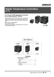
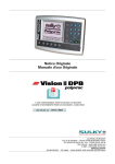
Figure 1: Typical ERIS Setup- sending rate instructions
GPS Receiver/Antenna
Third-party
Controller
Data Module (Treatment Plan)
RS 232C
Interface
(Port A)
GPS
Data
Rate
instruction
ERIS Custom Interface Cable
Fused Power Supply 9 - 48V DC
Figure 2: Typical ERIS Setup- receiving rate instructions
GPS Receiver/Antenna
Third-party
Controller
(Port A)
GPS
Data
ERIS Custom Interface Cable
Rate instruction
RS 232C
Interface
NOTE: Power Supply as normal via Pro-Series 50-way 'D' connector
33
PRO-SERIES - GPS, DATA LOGGING AND TRANSFER
The following sections give specific information for each type of implement controller. The sample messages
given, allow you to verify that the correct data is being transmitted via the RS232 serial interface. To verify the
message stream, connect the controller 9-way 'D' connector of the RDS interface cable to the COM port of the
PC, and view the data using a terminal emulation program such as Hyperterminal within Microsoft Windows.
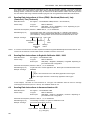
6.1
Sending Rate instructions to Vicon (EDW) / Berthoud (Bertronic) /Lely
(Centronic) Tive (Tivetronic)
RDS Cable Pt No.
Ref. Figure 1 : Use S/CB/268-1-053 (Tivetronic - see note below)
PS Port setup
Top port:
'RDS PF MODULE'
Bottom port:
'GPS(4800) + Vicon' / 'GPS(9600) + Vicon' depending on your
GPS baud rate configuration.
Serial data format (Slave): RS232 C / NMEA: 4800, 8, 1, N, no handshake
Data Message (1Hz)
The message starts with a '$' sign and ends with a '*' delimiter. Data fields are
separated by a comma. Only the RATE data field is communicated. Checksum
(error detection), Carriage Return and Line Feed are hexadecimal ASCII code.
Example message:
$RATE, 100.0 * 01 <13> <10>
Message string
identifier
Checksum
Line
Feed
Data field 1: Carriage
Return
Application
Rate
NOTE: To connect to the Tivetronic controller requires the 'Tivetronic/AgroNet RS232 Setpoint Receiver Module'. This
connects to the Tivetronic coaxial cable and has an RS232 connector on the back.
6.2
Sending Rate instructions to Bogballe Calibrator 2002 / 2003
RDS Cable Pt No.
Ref. Figure 1 : Use S/CB/268-1-047
PS Port setup
Top port:
'RDS PF MODULE'
Bottom port:
'GPS(4800) + Bogballe' / 'GPS(9600) + Bogballe' depending on
your GPS baud rate configuration.
Serial data format (Slave): RS232 C: 4800, 8, 1, N, no handshake
Data Message (1Hz):
3 bytes are sent to set the application rate. Each byte is hexadecimal ASCII code.
Example message:
4F 00 64
Byte 3: The lower 8-bit of the 16-bit binary application rate in kg/ha
Byte 2: The higher 8-bit of the 16-bit binary application rate in kg/ha
Byte 1
(The letter 'O')
In this example, Hex 0064 is a rate instruction for 100 kg/ha. The Calibrator 2003 can return a message
confirming the actual rate (see note 1 above). The Calibrator 2002 can not.
6.3
Sending Rate instructions to Amazone Amatron IIA
RDS Cable Pt No.
Ref. Figure 1 : Use S/CB/268-1-052
PS Port setup
Top port:
'RDS PF MODULE'
Bottom port:
'GPS(4800) + Amatron' / 'GPS(9600) + Amatron' depending on
your GPS baud rate configuration.
Serial data format (Slave): RS232 C: 4800, 8, 1, N, no handshake
Data Message (1Hz):
The message consists of 11 bytes in hexadecimal code.
Example message:
00 FF 30 53 00 00 01 25 00 00 54
4-byte identifier Rate instruction Checksum
(e.g. 125 kg/ha)
34
PRO-SERIES - GPS, DATA LOGGING AND TRANSFER
6.4
Sending Rate instructions to Fieldstar (or via Fieldstar to Väderstad / Horsch
(Agtron))
RDS Cable Pt No.
Ref. Figure 1 : You can use either S/CB/268-1-047 (Bogballe), S/CB/268-1-080 or
S/CB/268-1-053 (Tivetronic) cables. The only difference is the length of the lead.
PS Port setup
Top port:
'RDS PF MODULE'
Bottom port:
'GPS(4800) + FS TYPE 1' / 'GPS(9600) + FS TYPE 1' depending
on your GPS baud rate configuration.
Serial data format (Slave): RS232 C: 4800, 8, 1, N, no handshake
Data Message (1Hz):
The message starts with a '$' and ends with a '*' delimiter. 5 data fields are
separated by commas. Field 0 is a 5-byte header. The PS8000 transmits the
forward speed signal (field 1) and the rate instruction (the application rate will
appear in fields 2, 3 and 4). Checksum (error detection), Carriage Return and Line
Feed are hexadecimal ASCII code.
Example message:
$DOSES,8.52,100.0,100.0,100.0,*7F<13><10>
5-byte Forward Rate (seed) Check
(kg/ha)
sum
header speed
Line
Feed
Rate (Fert) Rate (Spray) Carriage
(kg/ha)
Return
(l/ha)
6.5
Receiving Rate instructions from Fieldstar
RDS Cable Pt No.
Ref. Figure 2 : Use S/CB/268-1-054
PS Port setup
Top port:
'Fieldstar type 1'
Bottom port:
'NOT USED'
The data message (1Hz) sent from the Fieldstar terminal is in the format shown above.
6.6
Sending Rate instructions to Väderstad
RDS Cable Pt No.
Ref. Figure 1 : Use S/CB/268-1-080
Otherwise, setup and the data format is the same as the Fieldstar terminal ( see 2.2.4 above)
6.7
Receiving Rate instructions from Agrocom ACT
RDS Cable Pt No.
Ref. Figure 2 : Use S/CB/268-1-032 (Pro-Series-PC Upload Cable). The power lead
with crimped terminals is not connected as the power supply to the PS8000 is via
the 50-way 'D' connector.
PS Port setup
Top port:
'Agrocom ACT'
Bottom port:
'NOT USED'
Serial data format:
RS232 C: 4800, 8, 1, N, no handshake
Data Message (1Hz):
The message starts with a '$' and ends with a '*' delimiter. 3 data fields are
separated by commas. Checksum (error detection), Carriage Return and Line
Feed are hexadecimal ASCII code.
Example messages:
$FERT,1,100.0*1B<13><10>
$SEED,2,100.0*09<13><10>
$SPRAY,3,100.0*57<13><10>
Plan
Type
Rate Carriage
(kg/ha Return
l/ha)
Line
Control Check
sum
Feed
channel
on PS8000
35
PRO-SERIES - GPS, DATA LOGGING AND TRANSFER
6.8
Receiving Rate instructions from Hydro-N Sensor
RDS Cable Pt No.
Ref. Figure 2 : Use S/CB/268-1-032 (Pro-Series-PC Upload Cable). The power lead
with crimped terminals is not required as the power supply to the PS8000 is via
the 50-way 'D' connector.
The cable connects to the junction box of the Hydro Agri 'Tractor cable harness'
(ref. section 5 of their operation manual).
PS Port setup
Top port:
'Hydro-N Sensor'
Bottom port:
'NOT USED'
Serial data format:
RS232 C: 4800, 8, 1, N, no handshake
Data Message (1Hz):
The PS8000 should be receiving the following message format,
Example message:
$AR0150,1F<13>
Header
Check
sum
Rate
(kg/ha
l/ha)
6.9
Carriage
Return
Sending Rate instructions to LH5000 V4
RDS Cable Pt No.
Ref Figure 1: Use S/CB/268-1-073. There is a 25-way female ‘D’ on the rear of the
5000 which is the ‘GPS’ port. This requires an LH5000 – DataLink RS232 cable to
which the RDS cable is connected.
PS Port setup
Top port:
'RDS PF MODULE'
Bottom port:
'GPS(4800) + LH5000 v4' / 'GPS(9600) + LH5000 v4' depending
on your GPS baud rate configuration.
Serial data format (Slave): RS232 C: 9600, 8, 1, N, no handshake
Data Message (1Hz):
NB. The LH 5000 must be configured to have the GPS switched OFF. This stops it
looking for the LH Data Link. The message consists of 8 bytes in hexadecimal
code. The rate instruction is a 4-databyte field. In the example, a rate of 200 l/ha set
on the PS8000 is sent as '40 0D 03 00' or 200,000 ml/ha.
Example message:
D2 00 04 40 0D 03 00 26
Check
sum
2-byte
identifier
No of
Rate
data bytes (g/ha ,
ml/ha)
6.10
Sending Rate instructions to Raven SCS Console
RDS Cable Pt No.
Ref Figure 1: Use S/CB/268-1-053.
PS Port setup
Top port:
'RDS PF MODULE'
Bottom port:
'GPS(4800) + RAVEN' / 'GPS(9600) + RAVEN' depending
on your GPS baud rate configuration.
Serial data format (Slave): RS232 C: 9600, 8, 1, N, no handshake
Data Message (1Hz):
Example message:
$R,RC,100<13><10>
Raven Identifier
Carriage
Return
Rate Change
Rate
Line
instruction
(l/ha,
Feed
kg/ha)
36
PRO-SERIES - GPS, DATA LOGGING AND TRANSFER
Document History
Issue 1:
5/1/04
Replaces UK202-5.
37