1
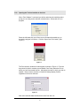
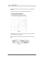
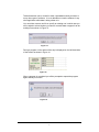
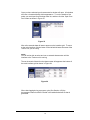
TechneWorks
Operator’s Manual
v1.0
Introduction
Welcome to TechneWorks.
This software has been designed to enable you to get the most from your Techne
equipment, Tecal Calibrators, our TU-20 range of portable thermo-regulators and
Fluidised baths. Where applicable you will be able to:
§
§
§
§
§
Input set points
Read unit temperature
Perform switch test functions
Create and run temperature cycle programs specifying set point, ramp rate and
hold time
Interface to external thermometers such as the Accu-Temp, Accu-temp II,
Cropico 3000 series and ASL250
The enabled version of the software will enable you to:
§
§
Calibrate Tecal units
Output the contents of the on-board RAM
Before running the software please make sure that your equipment is connected to
the computer using a suitable RS-232 or USB cable (please consult your equipment
manual for further details).
1
1.00
Opening the Techne Interface to the Unit
When “Run Software” is selected you will be asked to select which product
group you are using as the selection window below. Select and ok to run
program.
Down the left-hand side you will see a row of buttons that enable you to
access the program’s functions. Click the ‘Open Com Port’ button. (See
Figure 1)
Figure 1
The Port selection window will then appear as shown in Figure 2. From the
drop down list (which contains your available Com Ports) select the Port to
which you have connected the unit. Also select the units in which you wish to
operate. Note, however, that the unit itself will always display Celsius
regardless of the units selected.
Figure 2
After a few seconds data should start to arrive from the unit.
2
Figure 3 illustrates how the data is presented.
Firstly, you will see in the black box in the top left the serial port name in
yellow and the model name in white.
Figure 3
The data grid to the right contains the temperatures, units and date and time
of the reading. Also in the second column, which contains the value of the set
point, is a small button marked ‘Set’. This will enable you to manually alter
the set point at any time as will now be explained.
2.00
Manually Changing Set Points
Set points can be manually changed by clicking the ‘Set’ button.
Figure 4 shows the set point window. Note that you are able to enter the set
point (in your chosen units) and also specify, if required, the rate at which the
temperature is increased or decreased. Checking the Max Ramp box
instructs the unit to go to the new set point as quickly as possible. Click ‘OK’
to send the new set point to the unit.
Figure 4
3
3.00
Graph Output
TechneWorks maintains a real time trend graph of all the channels being
recorded.
With reference to Figure 5, the following channels are plotted:
§
§
§
§
Block set point (broken black line)
Block temperature (solid black line)
External thermometer channels (see later)
Switch state, where applicable (solid blue line)
Figure 5
It is also possible to specify the range of the vertical axis and to specify the
number of decimal places. (Figure 6).
The horizontal axis is a time base with vertical time bars every twenty updates.
Figure 6
4
3.00
Configuring and Running Temperature Programs
Click the ‘Program Set Up’ button. The program display grid will then appear
as shown in Figure 7.
Figure 7
To input step data, double click the first row of the grid. The data input panel
which then appears enables you to enter all the data required to specify a
step.
The required values are:
§
§
Set point
Ramp rate and hold time
When you have entered this data click ‘OK’ or to clear all entries in that step
click ‘Clear’ button as shown in Figure 8.
Figure 8
Proceed as above for all of your required steps. Note that it is possible to
leave gaps although this is not recommended. Once all steps have been
entered the program display grid will look similar to Figure 9.
Figure 9
5
Once you have completed your program configuration it can be saved, and
loaded at any time using the File option of the main menu located across the
top the window.
Figure 10
4.01
Running a Program
At the bottom of the display window you will see a row of buttons and other
controls. See Figure 11.
Figure 11
These enable you to stop, start and pause a program, to specify the logging
interval and, on suitable models record switch test data. To run your tests
click the ‘Start Program’ button.
A file dialog box will then appear that will enable you to save data as tab
delimited text as shown in Figure 12.
Figure 12
6
Tab delimited text can be viewed in either a spreadsheet word processor or
many other types of software. It is not advisable to view the software in any
other application whilst data is being written to it.
You can either create a new file or specify an existing one in which case you
will be asked to select whether you want to overwrite data or append it to the
existing file as shown in Figure 13.
Figure 13
During a program run the status of the step is displayed on the left-hand side
of the screen as shown in Figure 14.
Figure 14
When a program is completed you will be prompted to repeat the program
again should you so wish.
Figure 15
7
5.00
Switch Test Function
Certain models, such as the Tecal H Calibrators, enable thermostat switches
to be tested. This is done by inserting the bulb of the switch into the Block
insert and connecting the switch wires to the screw terminals on the front of
the unit.
Firstly, configure a program, usually two set points, in between which you
know that the contacts will open and close. Specify the ramp rate suitable for
particular type of switch.
The ‘Start Program’ button is then clicked having first made sure that the
Switch Test box is checked. You will then be prompted to show the serial
number of the switch under test. See Figure 16.
Figure 16
5.01
Viewing Switch Test Results and Creating Calibration Certificates
Once you have completed all of your switch tests data will be saved in two
forms. The first of these is the usual tab delimited text file that we discussed
earlier. There is also a special log file that records every change over of
switch contacts during a program run. This is accessed by clicking on the
‘Switch Test Log’ button upon which the switch test analysis window will
open.
Each row on the grid records an individual contact changeover event where,
with reference to Figure 17, the columns record the following:
§
§
§
§
§
Switch identity
The ‘From’ and ‘To’ set points (from which it is possible to deduce
whether the Block temperature was falling or rising).
Contact state (Open’ means the contacts have opened. ‘Closed’ means
contacts have just closed).
Block temperature at which the contacts changed over
Date and time of event
8
Figure 17
Creating a Certificate is simplicity itself.
Select the rows from the grid for the switch whose certificate you are creating.
Then click on the ‘Certificate’ tab at the top of the window.
You will see the image of your Certificate displayed on the screen. The
switch ID and other even data will have automatically been transferred to your
certificate, as shown in Figure 18.
Figure 18
Additional information required for the certificate is entered via the
‘Information’ tab again near the top of the screen. (See Figure 19).
Figure 19
9
This information can be saved for future use by clicking the ‘Save Default
Data’ button on the left-hand side of the screen.
You can then print the certificate by clicking the ‘Print Record’ button.
Once you have finished with all of the information in the log file it may be
emptied by clicking on the 'Clear Log’ button as shown in Figure 20.
Figure 20
5.02
A Note on Printing to PDFs
Software is readily available (some of it is free) that will enable you to
generate PDF files. These are permanent records that can be easily printed
and e-mailed as appropriate. When the ‘Print Record’ button is clicked, a
standard Windows print dialog box appears as shown in Figure 21.
Figure 21
Your PDF writer should appear as a virtual printer when you drop down the
‘Name’ list in the box. Selecting this option will output the image of the
certificate to a PDF file rather than directing it to a printer.
10
5.03
Including a Logo on your Certificate
Should you wish to incorporate a company logo into your certificate this is
done by saving, in either bitmap or JPEG format, your logo image in the same
folder as the TechneWorks .exe program file. The exact size of your picture
will depend upon the printer resolution but should typically be somewhere in
the range of 600 x 200 pixels. The image will be automatically positioned in
the top right hand corner of the certificate.
6.00
Using TechneWorks with External Thermometers
An important feature of TechneWorks is its ability to communicate with a
range of precision thermometers. These are:
§
§
§
§
Tecal Accu-Temp
Tecal Accu-Temp II
Cropico 3000
ASL F250
The purpose of this is to provide a highly accurate and traceably calibrated
reference for the block temperature. On each instrument two temperature
channels are supported. The second channel is most commonly used for
units under test when performing comparison calibrations.
The thermometer is chosen from the ‘External Thermometer’ menu item as
shown in Figure 22.
Figure 22
11
Once you have selected your thermometer its window will open. All windows
will have a characteristically similar appearance. To run the interface, first
select your serial port from the drop down list, and then click the ‘Open Com
Port’ button as shown in Figure 23.
Figure 23
After a few seconds data will start to appear on the interface grid. To return
to the main interface click the button on the left which bears the name of the
Techne unit you are using.
NOTE:
You will not be able to select and run an external thermometer until the
interface to the Techne unit is running.
The two channels of data from the thermometer will appear at the bottom of
the main interface grid as shown in Figure 24.
Figure 24
When data logging during a program cycle (See Section 4.00) the
thermometer channels will be included in the tab-delimited text file that is
generated.
12
7.00
Utilities
NOTE:
System utilities are only available in the TechneWorks enabled version. In
which case only those applicable will be available. Access to the utilities will
be denied until the main interface is running. The utilities will also be
unavailable when a program is running.
The utilities are accessed by clicking the ‘Utilities’ button - as shown in Figure
25.
Figure 25
When the button is clicked the Utilities window will appear towards the top of
which you will see a row of four buttons. (See Figure 26) These give access
to the following functions:
§
§
§
§
Initialise
Re-sets the block gain to 1.0 and the block offset to 0.0.
RAM Dump
Downloads the contents of the unit’s random access memory, which
contains the current gain and offset.
Calibrate
Enables the block to be calibrated and new gain and offset entered
Certificate
View and edit block calibration certificate data
Figure 26
13
7.10
Initialising Block Gain and Offset
Clicking the 'Initialise' button will force the block gain and offset to 1 and zero
respectively.
For the update to take effect you will need to switch the block off and back on
again. You will be prompted to do so once the update has been successfully
completed. (See Fig. 27).
Figure 27
Initialisation should be performed with great caution, as the calibration values
(gain and offset) will be permanently erased. It is recommended that this
action be only performed as part of a block calibration where data corruption
is suspected. This will enable the software to perform a block calibration
without reference to the suspected data.
7.20
RAM Dump
The RAM dump downloads, in hexadecimal format, the contents of the
Block’s random access memory. The main purpose of this is to extract the
Block’s calibration gain and offset as shown in Figure 28.
Figure 28
14
Performing a RAM dump will in no way affect the functioning of the Block
although it is stressed once again that although it is unlikely that
TechneWorks will produce bad calibration data, if in any doubt please
initialise the Block before performing As Found/As Left calibrations.
7.30
Calibration
The purpose of the block calibration is to generate a gain and offset that
enable the block temperature to reflect that indicated by an accurately
calibrated reference unit. The calibrations can be carried out using either of
the reference thermometers indicated earlier or, if the user has a thermometer
that is not supported, manual data entry can be carried out.
To access the calibration window the block interface must be running and if
needed, the reference thermometer interface must be running also.
7.31
Selecting Reference Temperature
If a reference thermometer is running it is possible to select either of the two
available channels as the reference channel. As shown in Figure 29, when a
reference thermometer interface is running, the channels are named
according to the thermometer selected. If no reference thermometer is
connected the channels will be greyed out and be unavailable for selection.
Figure 29
The figure also shows the different types of calibration tests that are available
namely:
§
§
Calibration check – which will be used to ensure that the Block is
performing to within limits
As Found/As Left where the block is first checked for calibration, new coefficient calculated and entered and then a second As Left check
performed.
15
7.32
Entering Calibration Points
A 5-point calibration is performed. If you are intending to calibrate over the
entire range of the unit it is possible to load pre-defined set points for that
purpose. This is done by clicking the ‘Load Defaults’ button, as shown in
Figure 30.
Figure 30
If, however, the unit is to be used over a limited range, it is better practice to
perform the calibration over the intended range. For this purpose the set
points are manually entered and can be saved for future use.
Once the set points have been entered click the ‘Start Calibration’ button.
You will then see the data grid, on the right side of the screen, begin to fill as
shown in Figure 31.
Figure 31
Figure 32
Below the grid you will see a box that provides information as to the current
status of the calibration test. See Figure 32.
The stability of each set point is determined by the reference temperature as
follows:
The last successive twenty reference readings must all be within ±
0.01 ° C of their mean value. As the values begin to approach stability
those readings that meet the criterion will be displayed with a pale
green background as opposed to white.
This process is repeated until all set points have been completed at
which stability point you will be prompted to click the ‘Calculate and
Send’ button shown in Figure 33
Figure 33
Please follow any on-screen instructions that appear and when prompted to
do so click the ‘Start Calibration’ button to commence the As Left part of the
test (if selected).
16
7.33
Generating a Calibration Certificate
Once a test has been completed generating a calibration certificate is a quick
and simple process. Close the calibration window and click the ‘Certificate’
button on the Utilities age.
The first step in the process is to provide the information required on the two
‘Information’ tabs as shown in Figure 34 and Figure 35.
Figure 34
Figure 35
17
The information, which can be saved for future use, includes:
§
§
§
§
§
Certificate number
Calibrator type and serial number
Customer details
Information on the reference thermometer and probe
A statement of the measurement uncertainties associated with the
calibration
The measurements taken during the test will be entered automatically into the
certificate for you.
A sample certificate is shown for you in Figure 36.
Figure 36
Clicking the ‘Print Record’ button enables a hard-copy of the certificate to be
produced (Please see earlier note with regard to printing to PDF’s.)
7.40
Including a Logo on your Certificate
Should you wish to incorporate a company logo into your certificate this is
done by saving, in either bitmap or JPEG format, your logo image in the same
folder as the TechneWorks .exe program file. The exact size of your picture
will depend upon the printer resolution but should typically be somewhere in
the range of 600 x 200 pixels. The image will be automatically positioned in
the top right hand corner of the certificate.
If you require further technical assistance please contact Barloworld Scientific Ltd
at: [email protected]
18