1
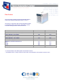
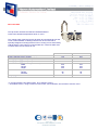
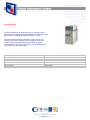
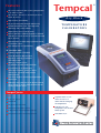
Features Choose from three models covering temperatures from -40°C to 650°C. Two versions - the basic ‘S’ and microprocessor based ‘H’ version. Tempcal Dry Block High accuracy and stability. Large interchangable multiple-drilled insert. Unique temperature zone - with improved uniformity and control stability. TEMPERATURE C ALIBRATORS Rapid heat-up and cool-down times. Calsoft calibration software supplied as standard with the ‘H’ versions and as an optional extra with the ‘S’ versions. RS232 interface for data and programme transfer, or real-time control. Fast settling time for rapid testing. ‘H’ versions only Software supplied as standard. 4 line 20 character LCD, 8 button keypad for entering programmes and viewing data. Ability to create/use/store programmes and test results internally. Programming of set temperature, ramp rate, hold time, ‘pause on switch changeover’ operation and hold until pause pressed. Switch test input for monitoring temperature thermostats. Calibration using the User Probe Interface which allows storage of the block temperature and the reading of the test sensor Tempcal® Junior Features Low cost option Hand-held Large block in 6 formats Separate heater on/off switch for fast cool down without changing set temperature Independent over temperature cut-out Indicators for over temperature cut-out and heater power Temperature sensor burnout protection Switchable °C/°F Maximum temperature 350°C ® Tempcal® Tempcal Software ‘Calsoft’ FOR BOTH H AND S MODELS, CALSOFT ENABLES YOU TO: Create, open, save and print programmes Log data from the calibrator while connected to the computer Open, save, view and print logged data Run a programme in real time mode N.B: The ‘S’ range of Tempcal calibrators must be connected to the computer at all times in order to run the programmes set up by CalSoft. FOR H MODELS ONLY, CALSOFT ENABLES YOU TO: Select 3 possible options to carry out a calibration Perform a calibration where you input the temperature of the probe manually Designed to provide a stable and accurate environment for the calibration of temperature sensors including liquid-in-glass and dial thermometers, thermocouples, RTD’s, thermal switches, transmitters and fluid filled bulbs, the Tempcal® range of Block Calibrators comes in two different formats and three temperature ranges. Model Min Temp°C Max Temp°C °C/°F Display Programme Switch Storage Test Input Software Perform a calibration using the User Probe Interface see optional accessories Perform a calibration requiring a switch test Send programmes to the calibrator Retrieve programmes from the calibrator Retrieve test results from the calibrator Erase test results Tempcal® 140S amb-45 140 Tempcal® 140H amb-45 140 Tempcal® 425S amb+20 425 Tempcal® 425H amb+20 425 Tempcal® 650S amb+25 650 Tempcal® 650H amb+25 650 - - Optional - - Optional - - Optional N.B: Tempcal 140 - using an external 4°chilled water supply connected to the integral cooling coil an actual temperature of - 40°C can be achieved. One Insert for Multiple Probes The insert blocks on the Tempcal® units have the advantage of a 38mm diameter to enable multiple probes of varying sizes to be tested at one time, making the units both economical and extremely flexible. The example shown is insert AB102M with five drilled holes from 3mm to 10mm diameter. Please contact our Sales Office if your requirement is outside our standard range. 38mm Insert Diameter Shows step 6 of a 10 step programme for a Tempcal® 650S. Step 6 has a set temperature of 100°C, a maximum ramp rate and a hold time of 10 minutes. Shows above programme running in real time mode. Programme is currently running step 1 of the 10 step programme, with data being logged and graphed at 60 second intervals. 10mm 8mm 6mm 3mm 4.5mm Tempcal® is a registered trademark of Haven Automation Shows a visual representation of a 10 step programme for a Tempcal® 650S. Specifications TEMPCAL® 140S/H TEMPCAL® 425S/H TEMPCAL® 650S/H TEMPCAL® JUNIOR Temperature Range °C Working Ambient °C Measuring Zone (M.Z.) Typical Accuracy °C Uniformity °C (in M.Z.) Immersion Depth amb-45 to 140* 10 to 30 0-50mm from base of well ±0.3 in M.Z. ±0.2 at 100 114.3mm amb+20 to 425 10 to 30 0-50mm from base of well ±0.3 in M.Z. ±0.2 at 300 114.3mm amb+25 to 650 10 to 30 0-50mm from base of well ±0.4 in M.Z. ±1 at 400 152.4mm amb+20 TO 350 10 TO 30 ±1.0 (100-300°C) - Stability ±0.05°C after 10 mins ±0.05°C after 10 mins ±0.09°C after 10 mins ±0.10°C @ 100°C ±0.15°C @ 200°C Display Resolution °C or °F Heating Rate 0.1 20°C to 100°C - 5 mins 0.1 20°C to 400°C - 15 mins 0.1 20°C to 600°C - 35 mins 0.1 20°C to 300°C - 5.2 mins (230V only) Cooling Rate Fan Cooling Programmable Ramp Rate °C/Min Switch Test Weight, Kg 100°C to 0°C - 9 mins N/A 400°C to 100°C - 25mins Automatic 600°C to 200°C - 30 mins Automatic 300°C to 100°C - 10.8 mins Automatic 0.1 to 10 on H Version on H Version 14.0kg (S) 14.4kg (H) 0.1 to 10 on H Version on H Version 9.2kg (S) 9.6kg (H) 0.1 to 10 on H Version on H Version 11.8kg (S) 12.2kg (H) 1.5kg Dimensions H x W x D 285 x 190 x 426mm 285 x 190 x 426mm 285 x 190 x 426mm 72 x 128 x 178mm (excluding handle) Voltage Hz Watts 230V or 120V 50/60 400 230V or 120V 50/60 700 230V or 120V 50/60 1100 230V or 120V 50/60 460 * The minimum temperature achievable can be reduced when used in conjunction with the CH-5 Chiller Unit - see optional accessories Tempcal® Interchangeable Insert Blocks Order Code Order Code Tempcal 140 and 425 (aluminium) Tempcal 650 (aluminium bronze) 5 x 6mm 1 x 10, 8, 6, 4.5, 3mm 2 x 6mm and 2 x 10mm 2 x 6mm and 2 x 12mm 1 x 6mm AB101M AB102M AB103M AB104M AB105M BB101M BB102M BB103M BB104M BB105M 5 x 1/4” 3/8”, 5/16”, 1/4”, 3/16”, 1/8” 2 x 3/8” and 2 x 1/4” 2 x 1/2” and 2 x 1/4” 1 x 1/4” AB1061 AB1071 AB1081 AB1091 AB1101 BB1061 BB1071 BB1081 BB1091 BB1101 Blank 1 x 9/16” 1 x 5/8” 1 x 11/16” 1 x 3/4” AB111 AB1121 AB1131 AB1141 AB1151 BB111 BB1121 BB1131 BB1141 BB1151 20mm 1 x 4, 5, 9, 11mm 1 x 6mm (immersion depth 40mm) 1 x 6mm and 1 x 9mm 9 x 3.18mm 1 x 19.5mm 1 x 10, 8, 6, 4, 3mm 1 x 12mm 1 x 15mm AB116M AB117M AB118M AB119M AB120M BB116M Description BB121M BB122M BB123M BB124M Supplied with a soft carry case with adjustable shoulder strap, removable mains lead, user manual and insert extractor tool.* In addition ‘H’ units are supplied with Calsoft Software and 1.5 metre RS232 lead. *Please state when ordering whether you require a 120V or 230V model. Tempcal Junior Unit Block Options Block Type A B C D E F Description 4 x 6mm 1 x 10, 8, 6, 4.5, 3mm 2 x 6mm, 2 x 10mm 4 x 1/4” 1 x 3/8”, 5/16”, 3/16”, 1/8” 2 x 1/4”, 2 x 3/8” N.B: The block on the Tempcal® Junior is fixed and cannot be removed. Supplied with removeable mains lead and user manual.* Optional Accessories CH-5 Chiller Unit User Probe Interface Enables fully automated and unattended calibration of temperature sensors The CH-5 Chiller Unit is designed for use in conjunction with the Tempcal 140 calibrators to achieve calibration temperature down to -40°C. The minimum temperature achievable on the Tempcal 140 models is 45°C below ambient, but by artificially cooling the heatsink of the units with water from the Chiller an actual temperature of-40°C can be achieved. The unit is designed to run on distilled or deionised water. For use on ‘H’ versions only Working Temperature Range 4-15°C Cooling Capacity 400 watts Temperature Control Thermostat on/off Electrical Control Manual Dimensions LxWxH (inc. pump) 430 x 235 x 524mm Bath Capacity 5 litres Pump Capacity 20 litres/min Cooling Probe A cooling probe is available for use with the Tempcal 425 and 650. It can be used to rapidly cool the block and to operate the unit around ambient temperature. The cooling probe must be inserted into a 10mm diameter or larger hole in the insert block. The User Probe Interface accepts K, J, N, T and E thermocouple types and 100 and 1000 ohm 3 and 4 wire RTD’s. The UPI can also be connected in series with a 0-20 mA loop and the current reading of the transmitter displayed. Simply install your sensor into the insert block and connect the wiring to the appropriate front panel terminals, switch the UPI on and select your sensor type. Create or run a programme either using the Calsoft Software or the Tempcal Calibrator memory and the Calibrator will save all the data throughout the run. When finished, data can be output as text, as a graph or a calibration certificate can be created for the sensor under test. The UPI is powered by a standard 9V battery. Sensor wires are connected to standard 4mm banana jacks. Probe Type Resolution Accuracy Range K t/c 0.1°C J t/c 0.1°C N t/c 0.1°C T t/c 0.1°C E t/c 0.1°C 0.3°C ±0.15% ±0.2% 0.3°C ±0.15% ±0.2% 0.3°C ±0.15% ±0.2% 0.3°C ±0.15% 0.3°C ±0.15% ±0.2% 0.2°C ±0.1% 0.2°C ±0.1% ±0.002mA ±0.2% -50 to 300°C 301 to 530°C 531 to 650°C -50 to 300°C 301 to 530°C 531 to 650°C -50 to 300°C 301 to 530°C 531 to 650°C -50 to 300°C 301 to 400°C -40 to 300°C 301 to 530°C 531 to 650°C -50 to 200°C 201 to 650°C -50 to 200°C 201 to 650°C 100 RTD 1000 RTD mA 0.1°C 0.1°C 0.1µA 0 to10mA 10.1 to 20.0mA Measurement House, Kingsway, Fforestfach, SWANSEA SA5 4EX, UK. Tel: +44 (0)1792 588722 Fax: +44 (0)1792 582624 e-Mail: [email protected] www.haven.co.uk Due to our policy of continual product development we reserve the right to amend this specification without notice. © Haven Automation Ltd 2004 Optional Accessory For Instrument Type Order Code Chiller Unit Cooling Probe User Probe Interface Calsoft Software only Calsoft Software and RS232 Cable Hard Carry Case Soft Carry Case UKAS Calibration Certificate Tempcal 140S/H Tempcal 425S/H, 650S/H Tempcal 140H, 425H, 650H Tempcal 140S, 425S, 650S Tempcal 140S, 425S, 650S Tempcal 140S/H, 425S/H, 650S/H Tempcal Junior All Models CH-5 FG-134 FG-136 FG-132 FG-133 FG-137 FG-154 On request Authorised Representative: GB92/1160 Designed by www.bluesky-media.net Ordering information Calibrate with confidence using the NEW Tempcal “Field” Range of Dri-Block Calibrators Following on from many years of experience with the high quality Tempcal S and H models the new F models have been introduced to offer a compact and lightweight, light weight, high performance range of Dri-Block temperature calibrators. Tempcal 140F Low temperature Portable Field Temperature Calibrator Minimum temperature Maximum temperature Temperature accuracy Temperature uniformity Temperature stability Display resolution Set point resolution Heating rate, 20°C to 100°C Cooling rate, 100°C to 0°C Large well Fan cooling Dimensions HxWxDmm Weight 45°C below ambient (typically -20°C in ambient of 25°C) 140°C ±0.3°C ±0.2°C ±0.05°C (after 10 mins) 0.01°C or 0.1°F 0.1°C or 0.1°F 5 minutes 9 minutes Ø38mm x 114 mm inserts Automatic 273x207x289 11kg Options • Inserts from standard list FINSAL• RS-232 interface plus software and cable • Carry case soft • Carry case hard • UKAS calibration certificate Tempcal 425F Medium temperature Portable Field Temperature Calibrator Minimum temperature Maximum temperature Temperature accuracy Temperature uniformity Temperature stability 20°C above ambient 425°C ±0.3°C ±0.2°C ±0.03°C at 200°C (after 10 mins) Temperature stability ±0.05°C at 425°C (after 10 mins) Display resolution 0.01°C or 0.1°F Set point resolution 0.1°C or 0.1°F Heating rate, 20°C to 400°C 12 minutes Cooling rate, 400°C to 100°C 21 minutes Large well Ø38mm x 114mm inserts. Fan cooling Automatic Dimensions HxWxDmm 270x170x255 Weight 6.3kg Options www.haven.co.uk • Inserts from standard list FINSAL• RS-232 interface plus software and cable • Cooling probe for rapid cooling of block • Carry case soft • Carry case hard • UKAS calibration certificate Tempcal 650F High temperature Portable Field Temperature Calibrator Minimum temperature Maximum temperature Temperature accuracy Temperature uniformity Temperature stability 25°C above ambient 650°C ±0.4°C ±1°C ±0.09°C (after 10 mins) Display resolution 0.01°C or 0.1°F Set point resolution 0.1°C or 0.1°F Heating rate, 20°C to 600°C 35 minutes Cooling rate, 600°C to 200°C 30 minutes Large well Ø38mm x 152mm inserts. Fan cooling Automatic Dimensions HxWxDmm 278x170x300 Weight 11 kg Options • Inserts from standard list FINSAB• RS-232 interface plus software and cable • Cooling probe for rapid cooling of block • Carry case soft • Carry case hard • UKAS calibration certificate Ordering information Tempcal 140F Tempcal 425F Tempcal 650F FDB140FD FDB140FP FDB140FY FDB140FR FDB425FD FDB425FP FDB425FY FDB425FR FDB650FD FDB650FP FDB650FY FDB650FR FDB140FS FDB140FT Tecal 140F 230v Tecal 140F 120v Tecal 140F 100v Tecal 140F 230v with RS-232 Tecal 140F 120v with RS-232 Tecal 140F 100v with RS-232 FDB425FS FDB425FT Tecal 425F 230v Tecal 425F 120v Tecal 425F 100v Tecal 425F 230v with RS-232 Tecal 425F 120v with RS-232 Tecal 425F 100v with RS-232 FDB650FS FDB650FT INSERTS FOR THE TEMPCAL 140 AND TEMPCAL 425 UNITS Part No Description FINSALA Insert 5 x 6mm probes aluminium FINSALB Insert 10 + 8 + 6 + 4.5 + 3mm probes aluminium FINSALC Insert 2 x 6mm + 2 x 10mm probes aluminium FINSALD Insert 2 x 6mm + 2 x 12mm probes aluminium FINSALE Insert 1 x 6mm probe aluminium FINSALF Insert 5 x 1/4” probes aluminium FINSALG Insert 3/8” + 5/16” + 1/4” + 3/16” + 1/8” probe aluminium FINSALH Insert 2 x 3/8” + 2 x 1/4” probes aluminium FINSALI Insert 2 x 1/2” + 2 x 1/4” probes aluminium FINSALJ Insert 1 x 1/4” probe aluminium FINSALK Insert blank aluminium FINSALL Insert 9/16” probe aluminium FINSALM Insert 5/8” probe aluminium FINSALN Insert 11/16” probe aluminium FINSALO Insert 3/4” probe aluminium FINSALP Insert 11 + 9 + 5 + 4 mm probes aluminium FINSALQ Insert 6mm probe aluminium (immersion depth 40mm) FINSALR Insert 6mm + 9mm probes aluminium FINSALT Insert 9 x 3.18mm probes aluminium FINSALZ Insert 20mm probe aluminium Haven Automation Ltd Measurement House, Kingsway Fforestfach, Swansea, SA5 4EX Tel: +44 (0) 1792 580255 Fax: +44 (0) 1792 582624 Email: [email protected] www.haven.co.uk Net weight kg 0.5 0.5 0.5 0.5 0.5 0.5 0.5 0.5 0.5 0.5 0.5 0.5 0.5 0.5 0.5 0.5 0.5 0.5 0.5 0.5 INSERTS FOR THE TEMPCAL 650 FINSABA Insert 5 x 6mm probes aluminium bronze FINSABB Insert 10 + 8 + 6 + 4.5 + 3mm probes aluminium bronze FINSABC Insert 2 x 6mm + 2 x 10mm probes aluminium bronze FINSABD Insert 2 x 6mm + 2 x 12mm probes aluminium bronze FINSABE Insert 1 x 6mm probe aluminium bronze FINSABF Insert 5 x 1/4” probes aluminium bronze FINSABG Insert 3/8” + 5/16” + 1/4” + 3/16” + 1/8” probes aluminium bronze FINSABH Insert 2 x 3/8” + 2 x 1/4” probes aluminium bronze FINSABI Insert 2 x 1/2” + 2 x 1/4” probes aluminium bronze FINSABJ Insert 1 x 1/4” probe aluminium bronze FINSABK Insert blank aluminium bronze FINSABL Insert 9/16” probe aluminium bronze FINSABM Insert 5/8” probe aluminium bronze FINSABN Insert 11/16” probe aluminium bronze FINSABO Insert 3/4” probe aluminium bronze FINSABP Insert 19.5mm probe aluminium bronze FINSABQ Insert 10/8/6/4/3mm probe aluminium bronze FINSABR Insert 12mm probe aluminium bronze FINSABS Insert 15mm probe aluminium bronze FINSABZ Insert 20mm probe aluminium bronze Visit www.haven.c o.uk Tecal 650F 230v Tecal 650F 120v Tecal 650F 100v Tecal 650F 230v with RS-232 Tecal 650F 120v with RS-232 Tecal 650F 100v with RS-232 1.1 1.1 1.1 1.1 1.1 1.1 1.1 1.1 1.1 1.1 1.5 1.1 1.1 1.1 1.1 1.1 1.1 1.1 1.1 1.1 for further information OTB-8 Series Digital Oil / Water Baths Haven OTB-8 Oil/Water Baths are a compact and reliable solution for the calibration of thermal sensors. Available in 2 models depending on range and application required. All baths are supplied complete with bath cover, drain tap, carry handles and hole to hold a certified sensor. The bath is fully insulated on the sides and the base and has a cooling coil fitted for connection to a cold water supply for use around ambient. Temperature stability as good as ±0.005°C Ranges covering -35°C* to 250°C 7 Litre or optional 12 litre capacity bath. * A Flow cooler is required to operate the OTB-8S model at below ambient temperatures. A Dip Cooler is required to operate the OTB-8HT model at below ambient temperatures TempWorks has been designed for use with OTB-8 Oil/Water Baths and the TU-20D controller on the ® refrigerated baths. It is a Windows based programme that connects via an RS232 connection to your computer. Programmes can be created, saved and recalled at any time as well as running in real time mode. Time, temperature and ramp rates can all be set up. Temperature can be set to two decimal places. Temperatures within the range of -35°C to 250°C can be programmed. Temperature Range °C Temperature Selection Temperature Stability °C (using water @ 40°C) OTB-8S Ambient +10 to 200 Digital OTB-8HT Ambient +10 to 250 Digital ±0.005% ±0.005% Pump Capacity litres/minute 10 Pump Capacity (mbar) Method of Control Temperature Sensor Adjustable over-temperature cut-out Low liquid level cut-out PC Interface TempWorks Software Bath Capacity Bath Opening (mm) 145 PID PRT YES YES YES RS232 Supplied As Standard 7 Litre 140 x 140 Use Flow Cooler -20°C Model FC-200 -35°C Model FC-500 Below Ambient Temperatures Dimensions: (mm) Bath L x W x H Head L x W x H N/A Internal Circulation only N/A PID PRT YES Plus audible alarm YES YES RS232 Supplied As Standard 7 Litre 140 x 140 Use Dip Cooler -20°C Model RU-200 -35°C Model RU-500 351 x 260 x 183 237 x 124 x 260 Flow Coolers The Flow Cooler enables the OTB-8S Oil/Water Bath to reach below ambient temperatures down to -35°C**. They work in conjunction with the thermoregulator (head) to continually extract heat from the bath fluid by means of a heat exchanger which is built into the unit. FC-200 FC-500 Minimum Achievable Temperature* (°C) -20 -35 Cooling Capacity: 20°C (watts) 140 210 Cooling Capacity: 0°C (watts) 140 210 Cooling Capacity: -10°C (watts) 110 200 Internal Capacity (ml) 200 200 Dimensions (Excluding handles) mm Width Length Height 235 420 300 370 430 325 Weight (kg) 19 39 * In a well insulated 7 litre bath system at an ambient of 20°C. ** At ambient of 20°C, using a mixture of 40% water, 40% antifreeze, 20% alcohol to achieve -35°C. DIP COOLERS The Dip Cooler enables the OTB-8HT Oil/Water Bath to reach below ambient temperatures down to -35°C. The cooling head of the Dip Coolers fit neatly and unobtrusively into the corner of the standard circulating bath and can be secured with a specially designed mounting bracket. Even if cooling can be achieved by cold tap water, a dip cooler is recommended as it conserves water and is easier and more convenient to use. Minimum Achievable Temperature* (°C) Cooling Capacity @ 0°C (watts) Cooling Capacity @ 20°C (watts) Cooling Capacity @ -10°C (watts) Nominal Dimensions (Excluding handles etc) mm Width Length Height Coil Dimensions (mm) Length Diameter Weight (kg) RU-200 -20 145 145 110 RU-500 -35** 240 240 230 235 420 300 370 430 325 85 75 19 85 75 39 * In a well insulated 7 litre bath system, at an ambient of 20°C. ** At ambient of 20°C, using a mixture of 40% water, 40% antifreeze, 20% alcohol to achieve -35°C. CH-5 Chiller Unit The CH-5 Chiller Unit is designed for use in conjunction with the Tempcal 140 calibrators and the OTB-8-H-T Digital Oil / Water Bath to achieve calibration temperature down to -40°C. The minimum temperature achievable on the Tempcal 140 models is 45°C below ambient, but by artificially cooling the heatsink of the units with water from the Chiller an actual temperature of -40°C can be achieved. The unit is designed to run on distilled or deionised water. Working temperature range Cooling capacity Temperature control Electrical control Dimensions L x W x H (inc pump) Bath capacity Pump capacity 4 - 15°C 400 watts Thermostat on/off Manual 430 x 235 x 524 mm 5 litres 20 litres/min Page 1 of 1 Fluidised Baths - SBL Series Working temperature span 50°C to 600°C (0-800°C with TC-8D) Control stability ±1°C (±0.3° with TC8-D) Three models to choose from Simple to operate The SBL range offers a working environment that is dry, easily accessible and totally free from the dangers associated with high temperature oil or salt baths. The units are designed to be bench standing and only require an electrical and air supply for operation. Air passes through the mass of the (AL203) particles via a porous plate in the base of the unit separating the individual particles and suspending them in free air, giving the properties of a liquid bath. Heaters are placed in the bath which allow temperatures of up to 600°C to be maintained. All the SBL range units have a stainless steel inner container insulated from the outer wall and a safety air pressure switch in the event of loss of air. All SBL Series fluidised baths are supplied as standard with an overspill flange and an initial charge of fluidising medium. Other available accessories include air compressor for when a convenient airline is not available, air pressure regulator/filter and stainless steel baskets to keep workpieces from touching the heater elements and to make retrieval easier. TC-8D Designed to improve the temperature stability and temperature setting obtainable with the energy regulator supplied as standard with the SBL Series of fluidised baths. The TC-8D is a self contained unit and is supplied complete with a chromel/alumel Type K thermocouple which fits into the sheath supplied with the SBL baths. The unit has digital set point and readout of bath temperature on an LED display and incorporates PID control. SBL-1 SBL-2 SBL-2D TC-8D 50 to 350 50 to 600 50 to 600 0 to 800 Temperature Stability °C, @ 50°C ±1 ±1 ±1 ±0.3 Heat up Time, minutes 20°C to maximum 60 105 105 N/A Cooling Time, minutes from maximum to 200°C Air Pressure, kPa (psi) 150 300 330 N/A 21 (3) 21 (3) 21 (3) N/A Air flow, max litres/min 57 57 57 N/A Weight of Medium (Kg) supplied with unit 13 16 32 N/A Temperature Range °C Overall size (mm) Diameter (excl. tap) 315 385 385 Height 470 470 695 Width 165 Depth 240 Height 140 Working volume (mm) Diameter 228 228 228 N/A Height 120 140 350 Refrigerated Baths Temperature Range -35°C to 100°C 7 or 12 litre capacity Temperature stability up to ±0.005°C These baths are a complete refrigerated circulating system for closed circuit applications for temperature ranges from -35 to 100°C. Two bath capacities are available, 7 litres (RB-5A) or 12 litres (RB-12A). Temperature control is by the thermoregulator giving four different combinations. COOLING (AT 20°C AMBIENT) Minimum Achievable Temperature (°C) * Maximum Achievable Temperature (°C) Cooling Capacity at 20°C (watts) Cooling Capacity at 0°C (watts) Cooling Capacity at -10°C (watts) Dimensions (L x W x H mm) Overall Size (with controller) Liquid surface to top of the bath Internal Dimensions Working length to thermoregulator Working depth – Max/Min (mm) Working Capacity – Max/Min (litres) THERMOREGULATOR Temperature Selection Temperature Stability @ 40°C (°C) Nominal Heater Power at 120V (watts) Nominal Heater Power at 230V (watts) Pump Capacity (litres/min) Pump Capacity (mbar) Method of Control Temperature Sensor PC Interface Software RB-5A -20 100 145 145 110 RB-12A -35 100 235 371 154 430 x 250 x 566 65 192 x 151 x 200 224 180 / 135 7.0 / 5.5 430 x 370 x 610 65 208 x 300 x 150 224 130 / 85 11.6 / 9.6 TE-10D Digital ±0.01 1000 1000 10 145 PID PRT NO TU-20D Digital ±0.005 1500 1800 10 145 PID PRT YES Via RS-232 OTBSoft ** (Optional Accessory) NO * Using a mixture of 40% water, 40% antifreeze, and 20% alcohol to achieve -35°C **OTBSOFT SOFTWARE OTBSoft has been designed for use with OTB-8 Oil / Water Baths and the TU-20D controller on the refrigerated baths. It ® is a Windows based programme that connects via an RS-232 connection to your computer. Programmes can be created, saved and recalled at any time as well as running in real time mode. Time, temperature and ramp rates can all be set up. Temperature can be set to two decimal places. Temperatures within the range of -35°C to 250°C can be programmed. Refrigeration units are available for connection to the system and can be controlled via the software. A Refrigeration Control Pack is needed to turn the refrigeration unit "on/off" when used with the software. FB08 Series Fluidised Baths Temperature range -100°C to 700°C Control stability ±0.2°C to ±0.5°C Three models to choose from Digital temperature indication/setpoint PID temperature control FB-08 Fluidised Baths are available in three models, the standard FB-08 covering temperatures of 50 to 700°C, the FB-08LT for low temperature operation, -100 to 200°C and the FB-08C designed for minimum supervision, works in conjunction with a supervisory computer via an RS232 (or optional IEEE488) interface. All FB-08’s are attractively finished free standing bench units with controls mounted on a recessed panel on the front of the unit. The inner container is well insulated and the outer case is vented so that it remains safe to touch even when the bath is operating at its maximum temperature. The inner container is filled from the top with alumina. When fluidised this medium is heated by four immersion heaters close to the container wall; the control thermocouple is close to the heaters. The heater elements are protected (by a pressure switch operated by the fluidising air) from excessive surface temperatures if fluidisation is lost. Clean dry air from an external source passes through two filters and two regulators, to reduce the pressure for the cyclone extraction system and for fluidisation. The fluidising air passes through a flowmeter and then to a plenum chamber from which it is distributed evenly around the inner container. The FB-08LT has provision for connection to a liquid nitrogen (LN2) supply and is fitted with an air drying system to avoid condensation of water when the fluidising air at ambient temperature is introduced into the cold fluidised bed. The LN2 supply is regulated by a flow meter on the front of the unit. Dust extraction is by means of ambient air drawn down past the probe plate and through a peripheral slot round the top of the inner container, then through a cyclone to the exhaust filter. Entrained medium, removed by the cyclone and discharged into a special jar accessible from the front of the unit, can be emptied back into the bath at regular intervals. Operating temperature is set by depressing and releasing the up/down buttons on the front panel of the control unit. Control of set temperature, incremental temperature steps, dwell times and control of dead bed state on the FB-08C can be programmed by the operator. All FB-08 precision fluidised baths are supplied with the temperature controller and a probe plate to help keep items being processed away from the heating elements of the bath and to assist in the retrieval of items from the bath. A probe carrier is also available, which holds up to eight probes of varying sizes (customer specified). It is specially designed to allow free flow of the fluidising media assuring constant uniformity, reducing short term temperature fluctuations and improving calibration accuracy. FB-08 FB-08LT FB-08C Temperature Range °C 50 to 700 -100 to 200 50 to 700 Dead bed ±0.01 Short Term @ 50°C ±0.2 Short Term @ 50°C ±0.2 @ 200°C ±0.2 Short Term @ 600°C ±0.3 Temperature Stability °C Short Term @ 600°C ±0.3 Long Term @ 50°C ±0.5 @ -100°C ±0.5 Long Term @ 50°C ±0.5 Long Term @ 600°C ±0.5 Long Term @ 600°C ±0.5 Display Resolution °C 1 1 1 Type of Control 3 term (PID) 3 term (PID) 3 term (PID) K Chromel/alumel Sensor Type K Chromel/alumel thermocouple Pt100 thermocouple Heat up Time, minutes 20 to 700°C, 105 20 to 200°C, 30 20 to 700°C, 105 Cooling Time, minutes 700 to 200°C, 165 200 to -100°C, 90 700 to 200°C, 165 Air Pressure, kPa (psi) 420 (60) 420 (60) 420 (60) Maximum Flow, litres/minute 127 170 127 Weight of Medium, kg 16 16 16 Overall Size L x W x H, mm 770 x 515 x 600 770 x 615 x 600 870 x 515 x 600 Working Volume : 165 x 385 165 x 385 165 x 385 Diameter x Depth, mm RS232 Interface NO NO YES Automatic Air Supply NO NO YES Programmable NO NO YES Fluidised Baths - BFS High Temperature Bath Temperature range 200°C to 1100°C Control stability ±0.5°C to ±3.5°C Designed for applications requiring a constant high temperature source for calibration. The BFS is supplied with a TC-5 temperature controller, a separate air supply control unit which incorporates two flowmeters for monitoring the air supply, a charge of fluidising medium (aluminium oxide) and air diffuser (zirconium oxide). The BFS has a hinged lid and a cylindrical bath. Substantial firebrick insulation is incorporated within the outer container and the lid. The inner container holds a layer of zirconium oxide, which acts as a heat insulator and a layer of aluminium oxide, the fluidising medium. The inner container is divided into inner and outer fluidised sections. Each area has a separate air supply which must be oil, water and dust free. The air supply is adjustable to obtain uniform fluidisation in both sections of the bath. Heaters are mounted in the firebrick insulation between the inner and outer container; heat is radiated inwards to the fluidised bath. An air extraction tube enables dust created by the bath’s operation to be removed if connected to an extraction duct or fan. The dust can also be trapped in a small tank of water. The TC-5 is used for setting, controlling and indicating the bath temperature. The TC-5 uses a chromel/alumel thermocouple, which mounts onto the back of the BFS and fits into the pocket of the inner container and is also fitted to the air flow control unit. Temperature Range °C Temperature Stability °C (short term) Display Resolution °C Type of Control Sensor Type Air Pressure, kPa (psi) Maximum Flow, litres/min For immersed object: Maximum load size Maximum surface area BFS with TC-5 Temperature Controller 200 to 1100 ±0.5 to 3.5 1 3 term (PID) digital set/readout K Chromel/alumel thermocouple 47 (7) 85 Weight of Medium, kg Overall Size L x W x H, mm Working Volume, Diameter x Depth, mm Overall Size L x W x H, mm (TC-5) 2.2 litres 1080mm² 16kg (aluminium oxide) 16.8kg (zirconium oxide) 686 x 686 x 876 (airflow controller adds 305mm to the width) 203 x 203 Top lid has a central opening 82.5mm square 430 x 305 x 140