1
18 SOLAHART OWNER’S MANUAL
%
'
&
$
('
)*
"
'
+
, # %
#
-
./ # , # *
'
0
)
)
#
1. 0
)
)
#
23
3
# %
#
+
6#
&
.
4
# 5
3
)
4
20
-+
)
4
20
-+
3
3
# %
*
3
5
5
5
5
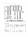
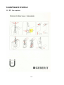
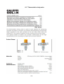
19 MAINTENANCE SCHEDULE
19.1 WC flow regulator
19.2 Tee box
19.3 Bulb globe
19.4 Fluorescent twin lamp
19.5 Extractor fan
19.6 Socket outlet for shaver
19.7 Thermostatic mixing valve
SINGLE MODULE BUILDING
ASSEMBLING, DISASSEMBLING AND RE-PACKAGING
USER’S MANUAL
Document ID: EDIL.76.07.1.EN_Rev.00 dated 11-06-2007
Language: English
for
UNITED NATIONS
NATIONS UNIES
INDEX
1.
HOW TO USE THIS MANUAL.......................................................................................................... 5
2.
GENERAL WARNINGS ...................................................................................................................... 5
3.
CONTENTS........................................................................................................................................... 5
4.
ASSEMBLING PROCEDURE ............................................................................................................ 6
5.
DISASSEMBLING PROCEDURE ................................................................................................... 25
6.
RE-PACKAGING PROCEDURE...................................................................................................... 26
1.
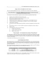
HOW TO USE THIS MANUAL
This manual contains the following graphic symbols:
Caution, danger:
Indicates situations or behavior that may put the user in danger
Warning:
Indicates useful information for the user
2.
GENERAL WARNINGS
This manual has the scope of guiding the workers in the assembling, disassembling and re-packaging procedures
of the prefabricated buildings. Lack of respect for the instructions contained in the manual will remove the
manufacturer from any and all responsibility.
The maneuvers for installation of the various parts and equipment are carefully described in this manual and have
been studied bearing in mind the weight and footprints of the pieces to be moved, as well as the time to perform
each operation.
The devices aimed at facilitating the completion of the various operations are supplied with the equipment. The
maneuvers request a minimum number of three workers. Should these indications be not respected, the
operations may become dangerous.
The workers involved to perform a specific procedure must constantly communicate with each other, monitoring
the correct procedure of the operation.
It is necessary that one operation is performed at a time, in order to avoid that the workers are placed in danger.
3.
CONTENTS
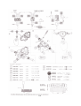
Each 20 feet ISO Standard Shipping Container contains all the components necessary to assemble three Single
Module Buildings.
The components necessary to assemble one Single Module Building are listed in the following pages. Pictures
help the users to identify and sort the components on installation site.
5
4.
ASSEMBLING PROCEDURE
The buildings are capable of being easily erected in a very short time completely by hand, without need for any
kind of heavy mechanical equipment.
Construction time for the Single Module Building will not exceed four hours with a skilled team of 3 workers.
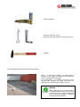
Minimum recommended hand tools:
-
Battery or electric drill/driver
-
Bits hexagon socket 7 and 10 mm
-
Bits for cross head Phillips® screws
-
Holesaw for metal 20 mm complete of arbour with
centre drill
-
Battery or electric jig saw
-
Blades for metal
6
-
Cutter with blades
-
Open jaw wrenches 13 mm
-
Double ended offset tubular box wrenches 13 mm
-
Hammer
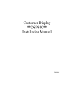
The assembling steps are described in the following:
Step 1 – Position the foundation concrete blocks (if
included in the supply) according to the dimensions
shown in the attached drawing #1.
As an alternative, it is possible to cast on site a
concrete slab, perfectly flat, whose dimensions are
3500x7130 mm and minimum height of 100 mm.
Warning
When positioning the concrete blocks it
is recommended to check that the level
is the same for all. It is also required that
the soil under the building is perfectly
draining and well ventilated.
7
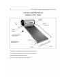
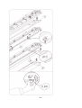
Step 2 – Assemble the supporting structure on the
ground, as shown in the drawing #2. First bolt the
initial and final pillars (items 5 & 7) with the junction
element for corner (item 10) using the bolts M8x30
complete of nut and washers (see detail “A”).
Step 3 – Bolt the central pillars (item 6) with the
junction element for central floor beam (item 12) using
the bolts M8x30 complete of nut and washers (see
detail “B”).
Step 4 – Bolt the central floor beam (item 3) with the
junction element for central floor beam (item 11) using
the bolts M8x30 complete of nut and washers (see
detail “B”).
Step 5 – Take the initial pillar and bolt it in the corner
at the base to the main floor beam (item 1) and to the
initial-final head floor beam (item 2). This operation
must be repeated also for the pillar in the opposite
side (see detail “A”).
8
Step 6 – Bolt the central cross beams (item 4) to the
two main floor beams (item 1). See detail “E”.
Step 7 – Erect the central pillars (item 6).
Warning
During the erection of the central pillars,
take care to bolt together the main floor
beams (item 1), the central cross beam
(item 3) and the central pillar (item 6).
See detail “B”.
Step 8 – The above operations must be repeated until
the floor structure is completed.
9
Step 9 – Lift the floor structure and position it above
the foundation concrete blocks.
Step 10 – Check that the floor structure is perfectly
levelled.
Step 11 – If the floor is not perfectly levelled, place
some shims under the floor structure.
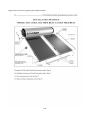
Step 12 – Place the lower U-shaped guides (items 18
& 19) on the external perimeter of the floor keeping
them 23 mm far from the external border of the floor
structure, as shown in the drawing #3. Fix them to the
structure using self-threading screws with hexagonal
head Ø4,2x19 every 45 cm approx. (see detail “F”).
10
Step 13 – Assemble the step floor. Take the floor
polyurethane sandwich panels 30 mm thick and place
them above the floor structure.
Warning
Floor panels must be cut with a jig saw
min. 60x110 mm at the corners and min.
60x55 mm at the centres near the
vertical pillars.
Step 14 – Start with the first panel 1000 mm wide
taking care to place the side with the groove against
the longitudinal U-shaped lower guide.
Step 15 - Proceed in this way until the floor is
completed.
11
Step 16 – Lay down the PVC sheet above the floor
panels.
Step 17 – Cut the PVC sheet near the vertical pillars.
Step 18 – Bolt the corner junction elements pillar-roof
right/left (item 13) at the top of the four corner pillars
(items 5 & 7). See detail “C” on drawing #2.
Step 19 – Bolt the central junction elements pillar-roof
(item 14) at the top of the central pillars (item 6). See
detail “D” on drawing #2.
12
Step 20 – Starting from the corner, bolt the main roof
beams (item 8) to the junction elements at the corner
and at the centre.
Step 21 – Bolt the junction element for cross roof
beams (item 15) both to the main roof beam (item 8)
and to the junction element central pillar-roof (item 14).
Step 22 – Complete the installation of the roof
structure at the corner bolting the head roof beams
(items 9).
13
Step 23 – Complete the installation of the roof
structure at the centre bolting the central roof beam
(item 9).
Step 24 – The supporting structure is now completed.
Step 25 - Assemble the wall panels, as shown in the
drawing #4. Place the first wall sandwich panel on the
long side of the building (item 20_1) inside the lower
U-shaped guide keeping the tongue towards the lower
short side of the building.
Step 26 – Proceed placing all the other panels until the
longitudinal wall is completed (items 20_2, 20_3,
20_4, 20_5, 20_6, 20_7), taking care to keep it in
vertical position. Screw all the panels at the base
using two self-threading screws with hexagonal head
Ø4,2x19 (see detail “G”).
14
Step 27 – Place the upper corner flashings (items 34)
at the top of the wall panels. See detail on drawing #5.
Step 28 – Each flashing must be fixed to the structure
using five self-threading screws with hexagonal head
Ø4,2x19 for each side of the profile.
Step 29 – Repeat the same procedure assembling the
other long side wall.
Step 30 – Assemble the lower short side wall. Insert
the wall sandwich panel with opening for Air
Conditioner (item 21_1) inside the lower U-shaped
guide keeping the groove towards the corner of the
building. See drawing #4.
15
Step 31 – Position the wall sandwich panel with the
window (item 21_2).
Step 32 – Position the wall sandwich panel (item
21_3) and the special wall sandwich panel groovesmooth (item 21_4). Screw all the panels at the base
using two self-threading screws with hexagonal head
Ø4,2x19 (see detail “G”).
Step 33 – Place the upper corner flashings (items 36)
at the top of the wall panels. See detail on drawing #5.
Each flashing must be fixed to the structure using five
self-threading screws with hexagonal head Ø4,2x19
for each side of the profile.
Step 34 – Assemble the upper short side wall. Insert
the special wall sandwich panel (item 22_1) inside the
lower U-shaped guide keeping the smooth side
towards the corner of the building. See drawing #4.
16
Step 35 – Position the door and over it the special wall
sandwich panel (item 22_2).
Step 36 – Position the wall sandwich panel with the
pre-fitted window (item 22_3).
Step 37 – Position the wall sandwich panel (item
21_4). Screw all the panels at the base using two selfthreading screws with hexagonal head Ø4,2x19 (see
detail “G”).
Step 38 – Place the upper corner flashings (items 36)
at the top of the wall panels. See detail on drawing #5.
Each flashing must be fixed to the structure using five
self-threading screws with hexagonal head Ø4,2x19
for each side of the profile.
17
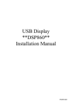
Step 39 – Place the threshold on the floor at the
bottom of the door so that to cover the U- shaped
guide and fix it to the guide itself with two selfthreading screws with hexagonal head Ø4,2x19.
Warning
It is strictly recommended to follow the position of the wall sandwich panels shown in the
drawings.
Step 40 – Stick the adhesive gasket on the external
border of roof flashings. See detail “H” on drawing #5
Step 41 – Assemble to roof covering, as shown in the
drawing #6. Place the first ribbed sandwich panel (item
24_2) so that the upper short side stay in the middle of
the central cross roof beam (item 9) and the external
long side comes out of 25 cm from the external border
of the building.
18
Step 42 – Proceed to assemble all the other roof
panels in the lower part of the building.
Step 43 – Stick the adhesive gasket on the
polyurethane foam of the roof panels in the lower part
of the building.
Step 44 – Assemble the roof panels in the upper part
of the building (item 24_1) so that they overlap those
previously put in place (see detail “M”).
Step 45 – Fix the roof panels using the self-screwing
screws with hexagonal head Ø6,3x120 and the fixing
elements (item 37) by the ribs of the roof panels,
tacking care that the screws perforate the supporting
roof beams. See details “I” – “L” – “M” – “N”.
19
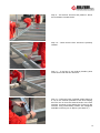
Step 46 – Place the roof flashing (item 37) in the upper
side as shown in detail “I” and fix it with self-threading
screws with hexagonal head Ø4,2x19 to the roof
panels every two ribs.
Step 47 - Place the vertical corner flashings (items
33_1 & 33_2) on the four corners of the building. Each
flashing must be fixed to the structure using four selfthreading screws with hexagonal head Ø4,2x19 for
each side of the profile. See detail “H” on drawing #5.
Step 48 – The external building is now completed.
Step 49 – Proceed with the internal finishing. Place the
skirting boards between the floor and the wall panels
all around the internal perimeter of the building.
20
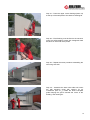
Step 50 – Place and fix to the floor panel by the
vertical pillars the L-shaped elements (item 40) using
self-threading screws with hexagonal head Ø4,2x19.
Typical for corner vertical pillars: one element only per
pillar.
Typical for central vertical pillars: two elements per
pillar.
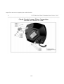
Step 51 – Mount into the appropriate frame the
window type Air Conditioner. The Air Conditioner shall
protrude on the outside.
Warning
The Air Conditioner is provided with
own Installation, Use and Maintenance
Manual. Please refer to it for any
additional information.
21
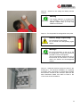
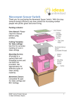
Step 52 – Mount on the ceiling the Battery Smoke
Detector.
Warning
The Smoke Detector is provided with
own Installation, Use and Maintenance
Manual. Please refer to it for any
additional information
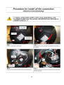
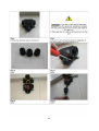
Step 53 – Fix the powder fire extinguisher to the pillar.
Caution, danger of poisoning:
Do not direct the jet at people.
Do not breath the extinguishing agent
vapors.
Warnings:
For more information on the use of the
fire extinguisher, consult the instructions
provided on the fire extinguisher.
The fire extinguisher load will last only a
few seconds. For this reason it must be
used in an efficient and knowledgeable
manner.
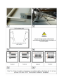
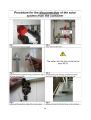
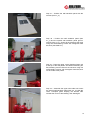
Step 54 – Install the electrical system as shown in the
drawing #11. The electrical installation is completely
pre-wired. Each component is provided with brackets
that shall be screwed to the structure. Start with the
Main Distribution Board that shall be fixed in the
corner near the Air Conditioner.
22
Step 55 – Fix all the distribution boxes at appropriate
positions.
Step 56 – Fix all the boxes with the socket outlets at
appropriate positions.
Step 57 – Fix the box with the light switches near the
entrance door.
Step 58 – Fix the internal lighting fixtures using the
appropriate metal clamps that shall be screwed to the
ceiling.
23
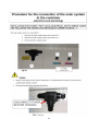
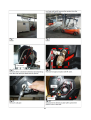
Step 59 – Fix the corrugated conduits using the plastic
clamps that shall be screwed to the panels/steel
profiles.
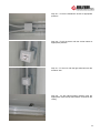
Step 60 – Make an hole in the panel over the door,
bring to the outside the cable and mount on the wall
the external lighting fixture.
Step 61 – Make an hole in the panel over the Main
Distribution Board and bring to the outside the cable
for the connection to the power supply.
Caution:
-
Do not use damaged cables or outlets.
Do not use the power outlets before making sure they are dry, clean and perfectly integral.
24
5.
DISASSEMBLING PROCEDURE
Unscrew the boxes, the lighting fixtures and the Main Distribution Board from the walls and remove the electrical
installation from the inside of the building without disconnecting the cables.
Remove the skirting boards from all around the internal perimeter of the building and unscrew the L-shaped
elements (item 38) from the floor by the vertical pillars.
Unscrew and remove the threshold on the floor at the bottom of the door.
Unscrew and remove the vertical corner flashings (items 33_1 & 33_2) at the four corners of the building, as
shown on drawing #5.
Unscrew and remove the roof flashing (item 37) in the upper side, as shown on drawing #6.
Unscrew the roof fixing elements from the ribs of the roof panels and remove them.
Remove the roof panels in the upper part of the building (item 24_1) and then all the other roof panels in the
lower part of the building (item 24_2).
Unscrew and remove the upper corner flashing (items 36) at the top of the wall on the upper short side, as
shown on drawing #5.
Unscrew at the base and remove in sequence all the wall panels: the wall sandwich panel with the pre-fitted
window (item 22_3), the wall sandwich panel (item 21_4), the door and the special wall sandwich panel (item
22_2), the special wall sandwich panel (item 22_1). See drawing #4.
Unscrew and remove the upper corner flashing (items 36) at the top of the other short side, as shown on drawing
#5.
Unscrew at the base and remove in sequence all the wall panels: the wall sandwich panel (item 21_3), the
special wall sandwich panel groove-smooth (item 21_4), the wall sandwich panel with the window (item 21_2),
the wall sandwich panel with opening for Air Conditioner (item 21_1). See drawing #4.
Remove the upper corner flashings (items 34) at the top of the long sides, as shown on drawing #5.
Unscrew at the base and remove in sequence the wall panels (items 20_7, 20_6, 20_5, 20_4, 20_3, 20_2,
20_1), as shown in the drawing #4.
Dismantle the roof supporting structure. See drawing #2.
Unbolt the central roof beam (item 9) from the central junction elements pillar-roof (item 14).
Starting from the corner, unbolt the main roof beams (item 8) from the junction elements at the corner (item 13)
and at the centre (item 14).
Unbolt the central junction elements pillar-roof (item 14) at the top of the central pillars (item 6).
Unbolt the corner junction elements pillar-roof right/left (item 13) at the top of the four corner pillars (items 5 & 7).
Remove the PVC sheet from the floor panels.
Remove the floor polyurethane sandwich panels starting from one side. See drawing #3.
Unscrew and remove the lower U-shaped guides (items 18 & 19) from the external perimeter of the floor.
Unbolt and knock-down the four pillars at corners and the two intermediate.
Dismantle the floor supporting structure. See drawing #2.
Unbolt the central cross beams (items 3/4) and the two head floor beams (item 2) from the main floor beams
(item 1).
Remove the foundation concrete blocks (if included in the supply).
25
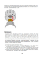
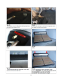
6.
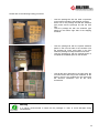
RE-PACKAGING PROCEDURE
All building components are suitable to be stored in a 20 feet ISO Standard shipping container. Please refer to the
following instruction for the packaging procedure.
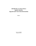
All the building components shall be packaged according to the following items (for details check the packing list):
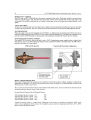
Package 1 - 20 feet ISO Standard shipping container.
Package 2 – Steel components of floor, roof and wall
supporting structure.
Package 3 – Sandwich type panels for wall and
sandwich type panels for floor.
26
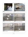
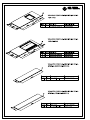
Package 4 – PVC sheathing rolls.
Package 5 – Sandwich type panels for roof and
sandwich type panels for floor.
Package 6 – Sandwich type panels for wall, sandwich
type panels with pre-fitted window and sandwich type
panels with pre-fitted frame for AirCon.
Package 7 – External doors.
27
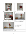
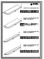
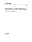
Package 8 – Concrete foundation blocks (if provided).
Package 9 – Air conditioner units.
Package 10 – Electrical system.
Package 11 – Miscellaneous (accessories, bolts,
junction elements, etc).
28
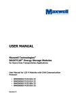
Please refer to the following loading procedure:
-
-
-
-
-
Load the package #2 with the steel components
on the bottom left side of the shipping container.
Place over it the package #3 with the sandwich
type panels and the package #4 with the PVC
rolls.
Load the package #5 with the sandwich type
panels on the bottom right side of the shipping
container.
Load the package #6 with the special sandwich
panels in the front left side of the container over
the package #2. Place some shims in the front
under the package to keep it lifted from the floor.
Load the package #7 with the external doors to
complete the available space on the left side.
Load all the other packages on the right sides: the
concrete blocks and the junction elements at the
bottom, then the air conditioners, the boxes with
the electrical installation and all the other
accessories.
Warning
It is strictly recommended to fasten all the packages in order to avoid damages during
transportation.
29
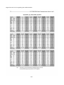
PACKING LIST