
1
® built with precisionware ® Standard & Auto User's Manual Revision D AppliedPrecision ® ii arrayWoRxe Standard & Auto User's Manual Revision D of the User's Manual for the arrayWoRxe Biochip Readers. Part number 04-720046-000 Rev D. 2004 Applied Precision, LLC. All rights reserved. No part of this manual may be reproduced, transmitted, stored in a retrieval system, or translated into any language in any form by any means without the written permission of Applied Precision, LLC. Information in this document is subject to change without notice. ArrayWoRx e is a registered trademark of Applied Precision, LLC. Cy3 and Cy5 are registered trademarks of Amersham Biosciences. All other registered names and trademarks referred to in this manual are the property of their respective companies. Applied Precision, LLC 1040 12th Ave. NW Issaquah, WA 98027 (425) 557-1000 FAX: (425) 557-1055 For questions or comments regarding this manual, please email: [email protected] AppliedPrecision Contents iii Contents 1 Getting Help 1 Using This Book ........................................................................................................................2 Document Conventions..............................................................................................................3 User Interface Description Conventions ....................................................................................3 Definitions .................................................................................................................................3 Mouse Terms .............................................................................................................................4 Using Online Help .....................................................................................................................5 Contacting Applied Precision, LLC...........................................................................................6 Customer Service Hotline ..........................................................................................................6 Corporate Offices.......................................................................................................................6 2 System Overview 7 Scanner Overview......................................................................................................................8 Workstation Overview .............................................................................................................10 Installation Requirements and Recommendations ...................................................................11 Workstation Network Configuration .......................................................................................12 Linux Configuration ................................................................................................................12 Windows Configuration...........................................................................................................12 Cable Connections ...................................................................................................................13 Safety .......................................................................................................................................14 Ultraviolet Light and Heat .......................................................................................................14 Class 1 LED Product Information............................................................................................14 Caution and Warning Labels ...................................................................................................15 3 Starting and Shutting Down the System 17 Turning On the Scanner and Workstation................................................................................18 Switch Between Linux and Windows ......................................................................................18 Opening the Main Scan Window .............................................................................................19 Closing the Main Scan Window ..............................................................................................21 Closing the Main Scan Window ..............................................................................................21 Turning Off the Scanner and Workstation ...............................................................................22 The Scanner Lights ..................................................................................................................23 4 Scanning Slides 25 e Handling Slides With arrayWoRx Standard ...........................................................................26 Insert the Slide into the Scanner ..............................................................................................26 Handling Slides With arrayWoRxe Auto..................................................................................27 Insert the Slides into the Cassette ............................................................................................27 Load the Cassette into the Scanner ..........................................................................................30 Viewing Slide Status................................................................................................................31 Cassette Idle Mode...................................................................................................................34 Use Preview to Define the Scan Area ......................................................................................34 Choose the Filter and Exposure ...............................................................................................36 Choose the Resolution and Sensitivity.....................................................................................37 Define the Advanced Options ..................................................................................................38 Advanced Tab Options ............................................................................................................38 Select Slides to Scan (arrayWoRxe Auto Scanner) ...................................................................40 Load / Unload a Single Slide ...................................................................................................40 Start and Stop the Scan ............................................................................................................41 Scanning a Slide Multiple Times .............................................................................................43 Remove Cassette from the arrayWoRxe Auto Scanner.............................................................44 View the File............................................................................................................................44 04-720046-000 Rev D/0804 iv arrayWoRxe Standard & Auto User's Manual 5 Refining Scan Settings 47 Choosing Scan Options............................................................................................................48 Working with Presets...............................................................................................................48 Exposure, Resolution and Sensitivity ......................................................................................51 Exposure ..................................................................................................................................52 Resolution ................................................................................................................................53 Sensitivity ................................................................................................................................54 Displaying Pixel Intensity in Panel View ................................................................................55 Using the Resolution Calculator ..............................................................................................55 Slide and Microarray Dimensions............................................................................................57 Extending the Scan Area..........................................................................................................58 Using Deconvolution ...............................................................................................................59 Focusing the Scanner ...............................................................................................................60 Flat-Field Calibration...............................................................................................................63 6 Viewing Image Data 65 Overview..................................................................................................................................66 Displaying an Image File in the Image Window......................................................................67 Scaling Display Intensities.......................................................................................................68 Measuring Feature Dimensions ...............................................................................................69 Examining Intensity Data with Data Inspector ........................................................................70 Selecting a Region of Interest in Data Inspector......................................................................71 7 Main Scan Window Reference 73 File Menu.................................................................................................................................74 Scan Menu ...............................................................................................................................75 Utilities Menu ..........................................................................................................................76 Help Menu ...............................................................................................................................77 Buttons.....................................................................................................................................78 Slide View ...............................................................................................................................79 Scan Settings Preset .................................................................................................................80 Scan Settings Tabs ...................................................................................................................81 Panel View...............................................................................................................................83 Scan Table ...............................................................................................................................84 The Status Bar..........................................................................................................................86 8 Image Window Reference 87 The Image Window Buttons ....................................................................................................89 Scale Image..............................................................................................................................90 File Menu.................................................................................................................................92 View Menu ..............................................................................................................................93 Options Menu ..........................................................................................................................94 Tools Menu ..............................................................................................................................95 Help Menu ...............................................................................................................................95 Data Inspector ..........................................................................................................................96 3D Data Graph .........................................................................................................................98 Histogram ..............................................................................................................................100 9 Saving Image Data 101 Overview................................................................................................................................101 Converting an Image File to TIFF .........................................................................................102 Saving Files to CD.................................................................................................................104 10 Introducing Linux and Gnome 107 Overview................................................................................................................................107 AppliedPrecision Contents v Logging On to and Off of Gnome..........................................................................................108 Getting Help on Gnome .........................................................................................................109 The Gnome Desktop ..............................................................................................................110 Managing Files with the Gnome File Manager......................................................................112 Working with the Floppy Disk and CD Drives......................................................................113 Using the GIMP to View TIFF Files .....................................................................................115 Capturing a Screen or Window in Gnome .............................................................................117 Editing Files with the gedit Text Editor.................................................................................118 Managing User Accounts.......................................................................................................119 Using LinuxConf ...................................................................................................................120 Changing a User's Password ..................................................................................................121 Deleting a User Account........................................................................................................122 Creating a New User Account ...............................................................................................123 File Permissions.....................................................................................................................125 Changing the Workstation Time/Date ...................................................................................126 Guidelines for using Linux ....................................................................................................126 11 Maintaining the System 129 Electrostatic Discharge (ESD) ...............................................................................................129 Cleaning the System ..............................................................................................................130 Replacing the Lamp Assembly ..............................................................................................130 Safety .....................................................................................................................................130 Measuring Intensity ...............................................................................................................133 Cleaning Slides ......................................................................................................................135 12 Troubleshooting 137 Problems with Images............................................................................................................137 Other Problems ......................................................................................................................138 Other Problems Cont'd...........................................................................................................139 Running the Service Script ....................................................................................................139 arrayWoRx Problem Report Form.........................................................................................142 Appendix A Filters and Dyes 143 Filters and Dyes supported by arrayWoRxe ...........................................................................144 Appendix B Signal-to-Noise 145 Index 149 04-720046-000 Rev D/0804 vi arrayWoRxe Standard & Auto User's Manual AppliedPrecision CONTENTS Using This Book ......................................................................2 Document Conventions............................................................3 Using Online Help ...................................................................5 Contacting Applied Precision, LLC.........................................6 1 GETTING HELP The arrayWoRxe documentation consists of this manual and the online Help system. This chapter describes the conventions used in this manual and how to open the online Help system. This manual provides information about the components, installation, operation, and maintenance of the arrayWoRxe Standard and arrayWoRxe Auto Biochip Readers. The online Help system provides the information included in this manual in addition to context-specific information that describes the scan software's user interface. 04-720046-000 Rev D/0804 2 arrayWoRxe Standard & Auto User's Manual Using This Book This manual is organized to help you quickly get started using arrayWoRxe and to find more detailed information about the system when you need it. Table 1 describes the organization of chapters in this manual. Table 1. Organization of Chapters Chapter Describes 1 How the manual is organized and how to open online Help. 2 The components of the system, installing the system, and safety. 3 How to start and shutdown the system and open and close the scan software. 4 The basic steps to scan a slide. 5 More details about refining the scan settings. 6 How to look at the image data generated from a scanned slide. 7 The Main Scan window, feature by feature. 8 The Image window, feature by feature. 9 How to convert image files to TIFF and save data files to CD. 10 An introduction to Linux and Gnome. 11 Basic maintenance tasks. 12 Error messages, troubleshooting steps. AppliedPrecision Chapter 1: Getting Help Document Conventions In order to make the information in this manual as easy as possible for you to locate and use, the following conventions are observed. Words in boldface are defined in the paragraph in which they appear. Italics indicate emphasis. • Bullets indicate items in a list or single-step procedures. 1. Numbered items are sequential steps for completing a procedure. Note indicates information about the previous paragraph or step in a procedure. Important indicates important or critical information about the previous paragraph or step in a procedure. Tip indicates helpful advice. See Also in the lower left corner of some pages, lists cross-references for the topic that you are reading. WARNING: Indicates important information regarding personal safety. CAUTION: Indicates important information regarding potential damage to equipment or software. User Interface Description Conventions Boldface indicates the names of buttons, menus, dialog box options, and fields. Initial Capitals indicate the names of windows, dialog boxes, and tabs. SMALL CAPITALS indicate the name of a menu command. ALL CAPITALS SAN SERIF indicate the name of a key on your keyboard, such as ENTER or DELETE. Uniform width font indicates text to enter on a command line or in the GUI. Definitions arrayWoRxe Applied Precision's product family of Biochip Readers. This consists of the original arrayWoRx scanner (now discontinued), the arrayWoRxe Standard scanner, and the arrayWoRxe Auto scanner. 04-720046-000 Rev D/0804 3 4 arrayWoRxe Standard & Auto User's Manual arrayWoRxe Standard The ‘e’ scanner that provides manual loading and unloading of single slides. arrayWoRxe Auto The ‘e’ scanner that has a 25-slide cassette with automated slide handling. Mouse Terms Pointer The mouse pointer is the icon that indicates the mouse position on the screen. It is usually a small black arrow, but changes shape to show what effect using it will have. For example, the pointer turns into a small, circle-shaped icon in the Image window to indicate that clicking a spot will center it. Point to Use the mouse to move the pointer to a position on the screen. For example, point to the File menu, means to move the mouse pointer to the File menu. Mouse button Mouse button refers to the left mouse button, unless specifically stated otherwise. For actions that require the middle or right mouse button, the mouse button is specified. For example, using the middle mouse button, drag the graph to rotate it. Click Press the left mouse button and quickly release it. To click an object on the screen, point to the object and then press the mouse button and quickly release it. Click refers to the left mouse button unless indicated otherwise. For example, click a file in the File Manager to open it, means to point to the file, press the left mouse button and quickly release it. Using the middle mouse button, click in a partially hidden window to make the window active, means to point to any place in the visible part of the window, press the middle mouse button and quickly release it. Double-click Press the left mouse button and release it two times in quick succession. For example, double-click the arrayWoRxe icon to start the Scan software, means to point to the icon and press and release the left mouse button two times quickly. Right-click Press the right mouse button and quickly release it. To right-click an object on the screen, point to it and then press the right mouse button and quickly release it. Drag Move an object on the screen to a new position by pointing to the object, holding down the left mouse button while moving the mouse pointer, and releasing the button when the pointer is at the new position. AppliedPrecision Chapter 1: Getting Help 5 Using Online Help The online Help system uses the workstation's Web browser to display its contents. Note You can view the Help without an Internet connection because all of the Help files reside on the workstation. To open the Help window: • In the Main Scan window Help menu, choose OVERVIEW OF SCANNING to open the Help window. or • While using a feature with a Help button, click the Help button to display help for the feature. To navigate the Help system: • • • Choose an item in the Contents pane of the Help window to view the topic. Click the SEARCH tab to display the Search pane. Type a word or short phrase in the field and click Search or press ENTER to display a list of topics that contain the word or phrase. To view a topic, click an item in the list of topics. Click the INDEX tab to display the Index pane. Click on a letter at the top of the pane or use the scroll bar to find an indexed word or phrase. To view the topic, click the indexed word or phrase. • Click topics. • Click File, CLOSE to close the Help window. 04-720046-000 Rev D/0804 in the lower right corner of some topics to display a list of related 6 arrayWoRxe Standard & Auto User's Manual Contacting Applied Precision, LLC If you have questions about arrayWoRxe, first refer to this manual or consult the online Help system. If you don’t find the information you need, contact us at one of the following phone numbers or addresses. Customer Service Hotline Phone: 1-800-862-5166 email: [email protected] Hours: 8:00AM - 5:00PM, Pacific Time, Monday - Friday Corporate Offices Internet Address: www.appliedprecision.com Corporate Headquarters Applied Precision, LLC 1040 12th Avenue NW Issaquah, WA 98027 USA Phone: (425) 557-1000 Fax: (425) 557-1055 European Office Applied Precision, LLC 121 High Street Marlborough SN8 1LZ United Kingdom Phone: +44 1672 518350 Fax: +44 1672 518359 Technical Publications email address: [email protected] AppliedPrecision CONTENTS Scanner Overview....................................................................8 Workstation Overview ...........................................................10 Installation Requirements and Recommendations .................11 Workstation Network Configuration .....................................12 Cable Connections .................................................................13 Safety .....................................................................................14 2 SYSTEM OVERVIEW The arrayWoRxe family of Biochip Readers consists of: • The original arrayWoRx scanner (now discontinued). • • The arrayWoRxe Standard scanner. The arrayWoRxe Auto scanner. The arrayWoRxe Standard scanner provides manual loading and unloading of single slides, whereas the arrayWoRxe Auto scanner has a 25-slide cassette with automated slide handling. The arrayWoRxe scanners integrate a high-performance CCD camera, fluorescence optics, a precision slide handling system, and sophisticated scanner software. The systems can scan microscope slides, simultaneously capture the intensities of up to 4 fluorescence wavelengths on each slide, and create data files. One multi-wavelength image file is created per scan, and separate TIFF files can be automatically generated for each wavelength. The arrayWoRxe scanners can assist you in a wide variety of applications, including: cDNA or oligonucleotide expression arrays, proteomics, combinatorial chemistry, antibody screening, SNPs (single nucleotide polymorphisms), and genomics. 04-720046-000 Rev D/0804 8 arrayWoRxe Standard & Auto User's Manual Figure 1. The arrayWoRxe Standard and arrayWoRxe Auto Scanners Scanner Overview The scanner components are the optical system, the precision motion control system, and the computer that is embedded in the scanner. The optical system is based on a CCD camera and white light source. The excitation filter is a band pass filter that selects a band of wavelengths from the full spectrum available from the white light source. These excitation wavelengths are delivered to the sample on the slide by fiber optics. The emission filter and other optics ensure that only the wavelengths emitted by the excited fluorophore on the sample reach the CCD camera. Note Virtually all wavelengths in the visible spectrum can be scanned by the arrayWoRxe scanners. The precision motion control system positions each section of the slide precisely in the optical path to ensure that the images of the sections are properly aligned in the acquired image. The embedded computer hosts the scanner software that controls the scanning process. This computer is connected to the arrayWoRxe workstation through a dedicated ethernet cable. It can be controlled and configured from the arrayWoRxe Main Scan window. AppliedPrecision Chapter 2: System Overview 9 Figure 2. Components of the CCD-camera Based Optical System The white light source is a high-intensity metal halide bulb and optical components that deliver a beam of white light to the excitation filter. The light generated by the bulb is a mixture of visible and ultraviolet wavelengths. The filter assembly holds up to four pairs of excitation and emission filters. One emission filter and one excitation filter are required to measure the intensity of a single fluorophore. Scanning software and motion control hardware place the appropriate filters in the light path for the fluorophore being measured. A tube lens with a focusing mechanism focuses the image collected by the objective into the CCD camera. The focusing mechanism is manually adjustable. The CCD camera, or Charge-Coupled Device camera, collects light from the emission filter and converts it into a digital signal that the scanner software processes to create an image file. The CCD chip is an array of semiconductor devices, or camera pixels. Each camera pixel stores an electrical charge generated by light from the emission filter. This charge is proportional to the intensity of the light, or number of photons, that reaches the pixel. Electronic circuitry on the camera converts pixel electron counts from the CCD chip into a digital signal that represents the intensity of each pixel. 04-720046-000 Rev D/0804 10 arrayWoRxe Standard & Auto User's Manual Workstation Overview The workstation is a personal computer that runs the Linux operating system. It provides a user interface to control the scanner, a CD recorder to archive data, an external network connection, and access to a Microsoft Windows environment (through VMWare). The workstation configuration is shown in the following table. Table 2. arrayWoRxe Workstation Configuration1 Minimum Workstation Configuration 1.6 GHz Intel Pentium 4 processor (or better) 1 GB RDRAM 64 MB video card 17" flat panel monitor 40 GB hard drive (arrayWoRxe Auto has an additional 80 GB hard drive) 1.44 MB, 3.5" floppy drive CD RW drive (CD archival is supported only when using arrayWoRxe software.) PS2 keyboard 3-button mouse RedHat Linux 7.1 Windows 2000 Scanning software on the workstation provides a user interface to the scanner, giving you control of the excitation frequency, resolution, exposure, and scan area. Analysis software, if installed, performs quantitative analysis on the ratio and intensity parameters associated with each spot such as mean ratio, standard deviation, etc. VMWare allows you to run Windows from the Linux desktop. After you start Windows, you can connect to a Windows network, connect to a printer, and install third party Windows applications just as you would in a typical Windows environment. Note VMWare does not support CD archiving (i.e., burning a CD). To archive data to a CD, use the arrayWoRxe software in Linux. 1 CAUTION: Installing any third party Linux applications on the arrayWoRxe workstation voids your warranty. (Third party Windows applications are allowed.) Configuration subject to change without notice. AppliedPrecision Chapter 2: System Overview 11 Installation Requirements and Recommendations Electrical Requirements • • Voltage: 100 - 240 VAC ± 10%. Frequency: 50/60 Hz. • Circuit Rating: 5 A maximum, 6.3 A fuse. • Transient over-voltages in accordance with Installation Category II in IEC 664. Space Requirements • 4 ft × 2.5 ft (120 cm × 80 cm) of counter space. Operating Environment Requirements • Indoor use. • Temperature: 65 - 77 ºF (18 - 25 ºC), daily variation of no more than 3 ºF (1.8 ºC). • Humidity: maximum relative humidity less than or equal to 50%. High humidity can result in condensation on the camera window. Excessive humidity may also reduce filter life. • • Altitude: up to 6550 ft (2000 m). POLLUTION DEGREE 22 in accordance with IEC 664. Communication Recommendations • It is suggested that the workstation be connected to a local area network for data storage. A connection to the Internet will provide access to Applied Precision's web site. To connect the system to a network you will need an IP address, domain name server address, and network mask. Important Applied Precision, LLC is not responsible for damage or harm to the workstation or scanner due to network security breaches. • Having a telephone in the same room as the system is also recommended to facilitate communication with Technical Support if necessary. UL 3101-1, First Edition, Underwriters Laboratories, Inc. defines POLLUTION DEGREE 2 as “Normally only non-conductive pollution occurs. Occasionally, however, a temporary conductivity caused by condensation must be expected.” 2 04-720046-000 Rev D/0804 12 arrayWoRxe Standard & Auto User's Manual Workstation Network Configuration This section describes the system's default network settings as delivered from the factory and how to modify these settings in order to connect the workstation to your network. The workstation contains two network ports. One is used for standard network communications and the other is used to communicate with the scanner. Specific configuration settings are required to allow networked data transfer and scanner operation. Note If you do not understand any of the terms in the following directions, or you do not know how to obtain local network information, please seek help from your IT Department before proceeding. Linux Configuration Linux uses the Eth0 and Eth1 Ethernet connections to communicate via your local network and to operate the scanner. We recommend that you connect to your local network via Windows running in VMWare (see Windows Configuration, below). Files that you want to move to and from Linux can be saved in the shared_data directory and transferred or printed via standard Windows networking protocols. Note It is not necessary to change the default Linux Eth0 network settings in order to network the workstation. Eth0 is the external network connection. It is configured by default to use a static IP address of 172.20.20.20, with a related /etc/hosts table entry. If you want to connect the Linux OS to your network, you can use Linuxconf (with 'root' privileges) to either reassign the static IP address to one that has been defined for your local network (typically done by your sysadmin), or to set Eth0 to DHCP for automatic IP address assignation. The physical connection for Eth0 is labeled "Network" at the network cable interface port on the back of the computer. Eth1 is the connection to the scanner. It is configured to use a static IP address of 159.159.159.2. The physical connection for Eth1 is labeled "Scanner" at the network cable interface port on the back of the computer. CAUTION: The Eth1 setting should NOT be modified. Modifying this setting causes communication to the scanner to fail. Windows Configuration Windows uses Network and Private Virtual to communicate via your local network and to connect to the shared_data directory in Linux. Network is the external network connection. It is configured by default to use DHCP to connect to your local network. The physical connection for Network is labeled "Network" at the network cable interface port on the back of the computer. If desired, this AppliedPrecision Chapter 2: System Overview 13 network connection can be assigned a static IP address using Windows Network and Dialup Settings. Private Virtual is the connection to the shared_data directory in Linux. It is configured to use a static IP address of 172.16.197.2. There is no physical connection for this communication path; it is accomplished via Samba in Linux and default virtual Ethernet port settings in VMWare. CAUTION: Private Virtual settings should NOT be modified. Modifying this setting causes communication with the shared_data directory to fail. Do not change the Windows 2000 account awuser or its password. Changing this account name or password will cause the workstation to become nonfunctional, due to internal networking conflicts. Cable Connections The scanner and workstation are connected by a single ethernet cable. Note that the workstation has two ethernet ports, one for the scanner and the other for a network connection. Figure 3 shows the correct cable connections. Figure 3. Scanner and Typical Workstation Cable Connections Workstation Scanner Keyboard Mouse Ethernet to Scanner Monitor Ethernet to network Power Ethernet to workstation Power Note The exact location of connectors on the workstation will depend on the computer included as part of the system. 04-720046-000 Rev D/0804 14 arrayWoRxe Standard & Auto User's Manual Safety The arrayWoRxe system is equipped with safety labels and interlocks to help protect you from potential injury that may be caused by ultraviolet light, heat, or the high voltage of the scanner's lamp. Ultraviolet Light and Heat The following hazards are associated with the scanner lamp assembly's high-intensity, metal halide bulb: • Damage to eyes and skin caused by exposure to ultraviolet radiation. • Burns caused by contact with a hot lamp assembly. • • Fire ignited by hot lamp assembly. Interaction of nearby chemicals with ultraviolet radiation. • Damage caused by placing apparatus too close to the scanner. To avoid injury or damage, do not remove the scanner cover. Also keep chemicals and equipment that are sensitive to ultraviolet radiation away from the scanner. Note The lamp access door and filter assembly are equipped with safety interlocks that turn off the lamp if the door is opened or the filter assembly is removed while the lamp is on. WARNING: Under certain conditions, the bulb can explode. If this occurs, the fumes can be toxic. Evacuate the room immediately and remain out of the room for at least 30 minutes. Call Applied Precision for a replacement bulb assembly. Class 1 LED Product Information WARNING: The arrayWoRxe system is classified as a “Class 1 LED Product (IEC 60825-1)” because it uses a bar code scanner with a red (660nm) LED. If the bar code scanner requires maintenance, please contact Applied Precision. AppliedPrecision Chapter 2: System Overview Caution and Warning Labels Hazardous Voltage Warning Label WARNING ! Hazardous Voltage Enclosed Voltage or current hazard sufficient to cause shock, burn, or death. Disconnect power cord before servicing. WARNING—HAZARDOUS VOLTAGE ENCLOSED Voltage or current hazard sufficient to cause shock, burn, or death. Disconnect the system by unplugging the power cord before servicing. Heavy Objects Caution Label ! CAUTION Heavy Object Can cause muscle strain or back injury. CAUTION—HEAVY OBJECT Can cause strain or back injury. Use proper lifting techniques when moving. Use proper lifting techniques when moving. Equipment marked with this label weighs 25 lb or more and should be lifted by two people. Hot Surfaces Caution Label ! CAUTION HOT SURFACES Do not touch. Allow surfaces to cool prior to servicing. 04-720046-000 Rev D/0804 CAUTION—HOT SURFACES Do not touch. Allow surfaces to cool prior to servicing. 15 16 arrayWoRxe Standard & Auto User's Manual AppliedPrecision CONTENTS Turning On the Scanner and Workstation..............................18 Opening the Main Scan Window ...........................................19 Closing the Main Scan Window ............................................21 Closing the Main Scan Window ............................................21 Turning Off the Scanner and Workstation .............................22 The Scanner Lights ................................................................23 3 STARTING AND SHUTTING DOWN THE SYSTEM This chapter describes how to turn on and turn off the system and start and close the scan software. It also describes the scanner lights. 04-720046-000 Rev D/0804 18 arrayWoRxe Standard & Auto User's Manual Turning On the Scanner and Workstation When you first turn on the scanner, you can perform scanner tasks such as focusing and previewing. Before you can perform a normal full resolution scan, the camera must cool down to its operating temperature. If arrayWoRxe displays a message that indicates the cameral temperature is too high, wait until the message closes before you try to perform a normal scan. Note The system ships without a Linux or Windows password. We highly recommend that administrative passwords be assigned to the system upon installation. To start the system: 1. Turn on the scanner by pressing the power button on the scanner's front panel. The Power, Status, and Lamp lights will light according to Table 3 on page 24. The arrayWoRxe Standard scanner The arrayWoRxe Auto scanner 2. Turn on the monitor. 3. Turn on the workstation. 4. Type the username awuser and press ENTER. If a Linux password is assigned to the system, type your password into the appropriate field and press ENTER again. Linux and Gnome will start up. Before you try to perform a normal full scan, wait until the Power and Lamp lights stop flashing and turn steady green. If arrayWoRxe displays a message that indicates the camera temperature is too high, wait until the message closes before you try to perform a normal scan. 5. Double-click the arrayWoRxe scanner icon on the desktop to start the software. Switch Between Linux and Windows The arrayWoRxe software runs on the Linux operating system. When you start the workstation, the Gnome desktop appears. However, you can use the VMWare application to run Windows from the Gnome desktop. You may need to run Windows to connect to your Windows network and to use optional analysis software (e.g., Tracker). AppliedPrecision Chapter 3: Starting and Shutting Down the System 19 To start Windows • On the Gnome Desktop, double click the Windows 2000 icon. VMWare starts and opens Windows. VMWare opens the Windows operating system in a window on the Linux desktop. You can typically switch between Windows and Linux by changing the position of the mouse pointer. (You can switch to Windows by moving the mouse pointer over the window that contains Windows and switch to Linux by moving the mouse pointer outside of that window.) However, in some cases (e.g., when you are shutting down Windows or using the Windows Full Screen option), you may need to use the CTRL+ALT key to gain control of the mouse in Linux. To switch from Windows to Linux: • Press CTRL+ALT to switch control of the mouse from Windows to Linux (or Linux to Windows). Opening the Main Scan Window The Main Scan window provides access to tools that control how the scanner scans a slide. Open the Main Scan window after you turn on the scanner and the workstation. Figure 4. The Main Scan Window Finished Normal Scan 04-720046-000 Rev D/0804 20 arrayWoRxe Standard & Auto User's Manual Use the following procedure to open the Main Scan window. To open the Main Scan window: 1. Double-click the arrayWoRxe icon on the desktop or Gnome panel. or Click the Gnome Main Menu button on the Gnome panel, and choose PROGRAMS, ARRAYWORX, START ARRAYWORX. Gnome Main Menu button The Analysis taskbar will open. Scan button 2. If arrayWoRxe does not open, click the Gnome Main Menu button on the Gnome panel, and choose PROGRAMS, ARRAYWORX, QUIT ARRAYWORX to properly close the program. Then repeat Step 1. 3. Wait for the Power light to stop flashing and shine steady green, then click the Scan button in the Analysis taskbar. The Main Scan window opens. If the scanner has not finished its initialization, (this takes about 2 minutes from the time the scanner is turned on) the Main Scan window opens partially and waits until communication can be established with the scanner. This partial window is normal. The full window will open when the scanner finishes initializing. AppliedPrecision Chapter 3: Starting and Shutting Down the System 21 Closing the Main Scan Window Before closing the Main Scan window, close any open scan dialog windows. Notes #1 Do not close the Main Scan window by clicking the Close box in the top right corner of the window. To ensure that the application closes properly, use the following procedure instead of the Close box to close the Main Scan window. #2 Closing the Main Scan window does not close any open Image windows or Image window analysis tools. Closing the Analysis toolbar does close any open Image windows, however. To close the Main Scan window: 1. Remove slides or cassettes from the scanner as follows: If you are using arrayWoRxe Auto and there is a cassette in the scanner, click the Eject button in the Main Scan window (or press the Eject button on the scanner) and remove the cassette after the door opens. or If you are using arrayWoRxe Standard and there is a slide in the scanner, click the Eject button in the Main Scan window (or press the Eject button on the scanner) and remove the slide after it is ejected from the slot. Click Eject 2. On the File menu, choose QUIT. Click Quit 3. If the Save Scan Settings question box appears, click Yes to save outstanding changes to the Preset that appears in the Scan Settings panel of the Main Scan window. Click No to exit without saving the changes, or click Cancel to return to the Main Scan window. 4. In the confirmation box, click Yes to close the Main Scan window. 04-720046-000 Rev D/0804 22 arrayWoRxe Standard & Auto User's Manual Turning Off the Scanner and Workstation CAUTION: Before turning off the scanner and workstation, you must close the Main Scan window as described in the previous section. You must shut down the Windows operating system before you shut down or log off of the Linux operating system. Do not shut down the Windows operating system by clicking the Close box in the top right corner of the VMWare Workstation window. This can corrupt Windows system files and require non-warranty service repairs. To turn off the scanner and workstation: 1. On the Analysis toolbar, choose File | Close to close the toolbar. Then close any other windows and applications that are running on Gnome or Linux. 2. If you are running Windows, close any windows or applications that are running on Windows. Then, from the Windows Start button, choose SHUT DOWN. In the Shut Down Windows dialog box, select Shut Down and click OK. When the VMWare dialog box appears, press CTRL+ALT and click Power Off. Important You will not be able to regain use of the cursor unless you press CTRL+ALT. 3. Close any windows and applications that are running on Gnome or Linux. 4. Click the Gnome Main Menu button. Gnome Main Menu Button 5. Choose LOG OUT on the Gnome Main menu. Click Logout See Also Working with Windows, 111 AppliedPrecision Chapter 3: Starting and Shutting Down the System 23 6. Choose Halt on the Logout dialog and then click Yes. Gnome and Linux will close and the workstation will turn off. Choose Halt Click Yes 7. Press the Power button on the front of the scanner to turn off the scanner. The Power light flashes while the system shuts down and turns off when the system is completely shut down. 8. If the Power light stays on and steady amber for more than 20 seconds, press the Power button a second time to turn off the system. Note Before the scanner completely shuts down, the Power light turns steady amber. 9. Turn off the monitor. The Scanner Lights The Power, Status, and Lamp lights on the scanner provide information about the status of the scanner. Each light has five states: green steady, green flashing, amber steady, amber flashing, and off. Table 3 shows the possible states of each light and what each state means. Scanner Lights 04-720046-000 Rev D/0804 24 arrayWoRxe Standard & Auto User's Manual Table 3. Scanner Light States and What They Mean State Power Status Lamp Green Steady Ready slide loaded lamp on Green Flashing Initializing busy scanning warming up cassette loaded, system ready to load slide (arrayWoRxe Auto only) bulb use over 1000 hrs Amber Steady Standby Amber Flashing powering down slide loading/unloading failed to light or bulb use over 1000 hrs Off power off no cassette loaded e (arrayWoRx Auto only) lamp off Note All three lights simultaneously flash amber if a system fault occurs. If there is a system fault, press the Power button to restart the system. If the problem persists, contact the Applied Precision Hotline. AppliedPrecision CONTENTS Handling Slides With arrayWoRxe Standard .........................26 Handling Slides With arrayWoRxe Auto................................27 Use Preview to Define the Scan Area ....................................34 Choose the Filter and Exposure .............................................36 Choose the Resolution and Sensitivity...................................37 Define the Advanced Options ................................................38 Start and Stop the Scan ..........................................................41 Scanning a Slide Multiple Times ...........................................43 View the File..........................................................................44 4 SCANNING SLIDES This chapter describes the basic steps required to scan slides. For more detailed information about how to use the features of the software to refine the scans, refer to Chapter 5, Refining Scan Settings. To scan slides, you insert them into the scanner and define settings in the scan software. The system then acquires the images and creates image files. An image file contains a table of intensity values and coordinates that describe excited fluorescence on the slide. The image file can be viewed in the Image window or converted to the TIFF format to be viewed in a TIFF image viewer. 04-720046-000 Rev D/0804 26 arrayWoRxe Standard & Auto User's Manual Handling Slides With arrayWoRxe Standard Insert the Slide into the Scanner Insert the slide into the scanner with the array facing down. Insert opaque slides face-up. To be detected, bar codes must be on the bottom of the slide facing down. Notes #1 Inserting the slide with the array facing down optimizes light collection. The refraction of the light as it passes through the slide can improve the signal by a factor of four. #2 If the Status light is on and green, there is already a slide in the scanner. If there is a slide in the scanner, click the Eject button on the Main Scan window or press the Eject button on the scanner front panel and remove the slide. Figure 5. The Eject Button Eject To insert a slide into the scanner: • Hold the slide by the end with the label or bar code and gently insert the slide completely into the slide slot. (Insert the slide with the array facing down unless it is an opaque slide. Insert opaque slides with the array facing up.) The Status light will flash amber as the scanner loads the slide and then turn green when the slide is loaded. Slide Slot Lamp Light Eject Button When the slide is loaded, the scanner's lamp automatically turns on. The lamp icon in the Main Scan window turns yellow and the Lamp light on the scanner's front panel turns steady green when the lamp is on and ready for scanning. AppliedPrecision Chapter 4: Scanning Slides 27 Handling Slides With arrayWoRxe Auto Insert the Slides into the Cassette Insert transparent slides into the cassette with the arrays facing down. Insert opaque slides with arrays face up. We do not recommend mixing transparent and opaque slides in the same scan job. If you do, you will need to perform a manual focus change and all transparent slides will need to be inserted with the arrays face up. This can reduce the signal-to-background on the transparent slides by a factor of two. Notes #1 If the Status light is shining a steady green or amber, there is already a cassette in the scanner. Click the Eject button on the Main Scan window or press the Load/Eject button located in front of the cassette door to open the door and eject the cassette. #2 If the Status light is off and the cassette door is closed, the scanner may have entered Cassette Idle Mode (see page 34). Press the Load/Eject button to open the cassette door. Figure 6. The Eject Button in the Software Eject Figure 7. The Load/Eject Button on the Scanner Load / Eject button 04-720046-000 Rev D/0804 28 arrayWoRxe Standard & Auto User's Manual The cassette holds up to twenty-five slides. Slots are numbered from one to twenty-five from the bottom of the cassette to the top. Slides can be placed into any of the slots and, once the cassette is loaded, the scanner will automatically determine the slot position of each slide. Figure 8. The Cassette Rear Bail Rear Bail Front Bail Cassette Guide Slot (one on each side of cassette) Front View Side View Bails on the front and back of the cassette hold the slides in place while the cassette is outside of the scanner. The front bail is moved to one side when loading slides into the cassette. After the cassette has been loaded into the scanner, the scanner opens the rear bails in order to load and unload the individual slides. See Also Slide and Microarray Dimensions, 57 AppliedPrecision Chapter 4: Scanning Slides 29 To insert slides into the cassette: 1. Grasp the cassette in one hand and use your thumb or index finger to move the front bail to the side. 2. Hold a slide by the end with the label or bar code and gently insert it completely into the cassette slot. Ensure that the slide is placed into the slot so that it is parallel to the bottom of the cassette. The scanner will not load slides that are cross-slotted (positioned so that one edge of the slide is higher in the cassette than the other). Insert transparent slides into the cassette with the arrays facing down. Insert opaque slides with arrays face up. 3. Repeat Step 2 for each of the slides that you want to insert into the cassette. 4. After all the slides have been loaded into the cassette, move the front bail so that it is positioned over the back edge of the loaded slides. 04-720046-000 Rev D/0804 CAUTION: When you are loading slides, do not place the cassette with the rear bails on a flat surface (such as a table or counter top). This can open the rear bails and cause the slides to fall out of the cassette when it is moved. 30 arrayWoRxe Standard & Auto User's Manual Load the Cassette into the Scanner An arrow on the top of the cassette points to the back of the cassette. The back of the cassette also has a double, rather than single, bail. When loading the cassette into the scanner, the back of the cassette is inserted first. To load a cassette into the arrayWoRxe Auto scanner: 1. Check the Status light. • If the Status light is shining a steady green or amber, there is already a cassette in the scanner. Click the Eject button on the Main Scan window or press the Load/Eject button located in front of the cassette door to eject the cassette. (Refer to the figures in the previous section.) or • If the Status light is off and the cassette door is closed, the scanner may have entered Cassette Idle Mode (page 34). To exit from Cassette Idle mode, press the Load/Eject button on the scanner. 2. Ensure that the front bail is positioned over the slides so that the slides do not slip out of the cassette. 3. Press the Load/Eject button to open the cassette door. 4. Place the back (arrow end) of the cassette into the scanner at an angle by gently setting the bottom-back end of the cassette down in the back of the cassette tray. AppliedPrecision Chapter 4: Scanning Slides 31 5. Lower the front end of the cassette so that its guide slots slide over the green guide pins on the inside-front of the cassette tray. Once the pins are set fully into the slots, the guide pins will hold the cassette in place. 6. Press the Load/Eject button. The scanner will pull the cassette into the system, close the door, check to ensure proper cassette positioning, and inventory the slides. If the cassette is not positioned properly, the system will automatically reopen the cassette door, eject the cassette, and display an error message. If this occurs, follow the instructions that are displayed in the error message. The Status light will shine steady amber once the cassette is loaded. After the scanner removes a slide from the cassette and loads it for scanning, the Status light will shine a steady green. Viewing Slide Status Once a cassette has been loaded and inventoried, all slots with detected slides will be displayed on the Scan Table tab of the Main Scan dialog. All of the detected slides will be automatically selected for scanning using the currently specified Scan Settings preset. The Scan Table displays the Slot, Scan, Preset, and Data Name for each detected slide. The tab also includes the Load Slide list, Multi-Scan, Disable, and Reset buttons. See Also Scan Table, 84 04-720046-000 Rev D/0804 32 arrayWoRxe Standard & Auto User's Manual Figure 9. Scan Table Tab Click here to list all slots available in cassette Click here to enable multiple scans of same slide Slot The slots in the cassette containing detected slides. Note The arrayWoRxe Auto Scan table displays the loaded slots at the top of the table. For example, if slots 2, 4, and 6 are the only loaded slots in a cassette, the table displays slots 2, 4, and 6 followed by slots 1, 3, 5, and 7. Scan Toggle button that determines whether or not the slide will be scanned. Click the button to toggle the setting. Blue indicates that the slide will be scanned; gray indicates that the slide will not be scanned. Preset Displays the default preset defined for the slide and allows different presets to be selected for each slide or multi-scan. Data Name Displays the slide identifier. If the slide identifier is being read from the bar code on the slide, the field cannot be edited. If the slide identifier is not being read from the bar code, this field will display a default slide name, which can be edited, that corresponds to the slot name. All files related to the scanned slides (e.g., panel, TIFF, etc.) will share the name displayed in this field. Note Data name lengths up to 70 characters are supported. AppliedPrecision Chapter 4: Scanning Slides 33 Load Slide Displays a list of all slots available in a cassette. Individual slides may be loaded and unloaded by selecting them from the list. Slots containing detected slides are displayed without parentheses; empty slots are displayed with parentheses. Tip You can use this option to try manually loading a slide that does not appear in the Scan Table but is known to be in the cassette. (On rare occasions, a slide is not detected during inventory.) If a slot contains a slide but it appears in the list with parentheses, you can select that slot and the scanner will attempt to re-detect the slide. If the slide can be successfully detected and loaded, it will appear in the Scan Table; however, parentheses will remain around the slide in the Load Slide list. Multi-Scan Allows a single slide to be scanned multiple times. (If only one slide is present, it is automatically added to the Scan table. If more than one slide is present, a dialog opens that allows you to choose which slide to multi-scan.) Once a slide is selected, it appears on a second (and, if applicable, third, fourth, etc.) line in the Scan Table. This allows the same slide to be scanned with different presets (exposure times, pixel sizes, resolution, etc.) The Scan Table can include up to 50 entries. Note additional entries in Scan Table after Slot 1 has been selected for Multi-Scan. (Different Presets can be selected for each multi-scan.) Disable Deselects the Scan toggle buttons on all of the slides in the table so that none of the slides are scanned. 04-720046-000 Rev D/0804 34 arrayWoRxe Standard & Auto User's Manual Reset Applies the selected preset to all of the slides in the table. This option also enables single scans for each loaded slot, removes all multi-scans, and resets all slide data names. Notes #1 The Multi-Scan dialog is displayed only for slides that are detected by the system (i.e., slides that appear in the Scan Table). #2 When you multi-scan a slide with Use Barcode For File Names selected, arrayWoRxe creates a file name for each scan by appending a scan number to the barcode. #3 When more than one slide is selected, the Preview area is cleared between scans. When performing a multi-scan on a single slide with no other slides selected, the Preview area is not cleared between scans. Cassette Idle Mode To protect the interior of the scanner from dust and other debris, an open cassette door closes after a period of scanner inactivity and the scanner enters Cassette Idle Mode. This mode is triggered when the lamp-cooling fan is automatically turned off (four minutes after the lamp is shut down either manually or automatically). If there is a cassette in the cassette tray when the scanner enters Cassette Idle Mode, the scanner pulls the cassette inside, closes the door, and inventories the slides. If there is no cassette in the tray, the scanner pulls the empty tray inside and closes the door. To exit from Cassette Idle Mode, press the Load/Eject button on the scanner. Note In Cassette Idle Mode, the Status light shines amber if there is a cassette loaded in the scanner. It remains off if there is no cassette loaded in the scanner. Use Preview to Define the Scan Area A preview scan is a single-channel, low-resolution scan that generates an image of the slide that you can use to locate the array's position. Preview scans can be performed while the camera is cooling and the lamp is warming up. This section describes two methods for using Preview to define a scan area that encloses the array. • Define the area based on a partial preview when you know the approximate location of the array on the slide. (This method is faster than obtaining a full preview.) • Define the area based on a full preview when you do not know the location of the array or when the array is randomly positioned on the slide. See Also Scanning a Slide Multiple Times, 43 AppliedPrecision Chapter 4: Scanning Slides 35 To define the scan area from a partial preview: 1. Make sure that that the Status light is shining steady green, indicating that there is a slide in the scanner. 2. Click the Area tab and drag the blue scan area rectangle to the edge of the Slide view area. (To drag the rectangle, position the mouse pointer inside the rectangle until it changes to . Then move the mouse pointer.) 3. Find the boundaries of the scan by clicking on a point in the Slide view area that is outside of the scan area rectangle. (Clicking on a point moves the slide and acquires a preview image of that point. This allows you to find the corners of the scan area.) 4. Position the blue rectangle so that it encloses the scan area. (To resize the rectangle, point to one side with the mouse until the pointer changes to . Then move the mouse pointer.) If you are defining the scan area for a batch of slides, leave some space between the blue rectangle and the array to account for variability in array printing. Figure 10. The Slide View Drag a side of the scan area rectangle to enclose the array 5. Make sure that the desired channel is marked as active in the Channels tab. To define a scan area from a full preview: 1. Make sure that that the Status light is shining steady green, indicating that there is a slide in the scanner. 2. Choose Entire Slide in the Preset list. 3. Click Preview and wait for the preview image to appear in the Slide View. 4. In the Slide View, drag the sides of the blue scan area rectangle so that the rectangle encloses the preview image of the array. If you are defining the scan area for a batch of slides, leave some space between the blue rectangle and the array to account for variability in array printing. 5. Make sure that the desired channel is marked as active in the Channels tab. Notes #1 Choose Scan, CLEAR PREVIEW to clear the preview image in Slide View. #2 If you know the dimensions for your scan, you can enter them manually in the text boxes on the Scan Area tab. 04-720046-000 Rev D/0804 36 arrayWoRxe Standard & Auto User's Manual Choose the Filter and Exposure You can choose the filter and an exposure for up to four channels. The number of channels that you choose for a scan is typically the same as the number of fluorophores that you want to measure. Note If you would like to add third party filters to your arrayWoRxe scanner, contact Applied Precision Customer Service at 1-800-862-5166 or [email protected]. Channel Each wavelength (dye) measured during a scan is represented as a channel in the scan software. A Filter name and exposure time is associated with each channel. Filter The Filter setting is named for the dye (fluorophore) to be measured. The scanner uses this setting to determine which filters to use for the scan. Exposure The time, in seconds, that the sample is exposed to light from the lamp during a scan. Figure 11. The Channels Tab Typical Settings: Number of channels 2 Ch 1: Filter Cy3 Exposure 0.10 Ch 2: Filter Cy5 Exposure 0.30 To define the channel settings for a scan: 1. Click the Channels tab in the Main Scan window. 2. Select the number of channels (between 1 and 4) for the scan. 3. Choose a dye name in the Filter drop-down list for each channel. The standard choices are: • CY3 • • CY5 Alexa 350 (DAPI)\ • Alexa 488 (FITC) 4. Enter an exposure for each channel. Click the Exposure field and type a value. You can use the left and right arrow keys on your keyboard to move the cursor in the box. Note The recommended minimum value for Exposure is 0.10, which is determined by scanner hardware. AppliedPrecision Chapter 4: Scanning Slides 37 Choose the Resolution and Sensitivity The Resolution and Sensitivity settings give you control of the pixel size and dynamic range of the image generated by the scan. • Sensitivity determines the dynamic range, or detail of information available over the range of intensities, of the image. (See Sensitivity on page 54.) • Resolution determines the size in microns of the area on the CCD chip that is represented by an image pixel. (See Resolution on page 53.) To choose the resolution for the scan: 1. Click the Image tab in the Main Scan window. 2. Select a pixel size in Resolution. Typical Settings: Sensitivity: High SNR Resolution: 9.7560 Select a pixel size Note Pixel sizes that appear with an asterisk in the drop-down box are interpolated using the next lower multiple resolution of the base (e.g., selecting a resolution 10.000* will interpolate from 9.756). When you select a pixel size, the approximate amount of memory required to store all of the files associated with the scanned image appears in the Status box. The file set size is determined by the resolution and size of the scan area, as well as the number of channels and whether TIFF files are created. 3. Select the Sensitivity. In most cases, use the High SNR sensitivity setting. For unusually bright samples, you may need to change the sensitivity setting to High Dynamic Range. 4. If you are performing a single channel scan with an exposure time greater than .15 second, select Stripe Scan mode. For shorter exposure times, unselect Stripe Scan. Note Stripe Scan∗ enables a fast scanning mode in which the shutter is left open and the exposure time is controlled by the speed of the stage motion. If you specify an exposure time that is shorter than the minimum scan time, the minimum time is used. Stripe Scan is automatically disabled for presets that contain more than one channel. Panel Scanning mode is used when Stripe Scan is not selected. ∗ Patent Pending 04-720046-000 Rev D/0804 38 arrayWoRxe Standard & Auto User's Manual Define the Advanced Options The Advanced tab allows you to specify that bar code data be used for the file name, automatically generate images in TIFF format, set the gain, and enable stitch panel flattening and connection. By default, all options on the Advanced tab are inaccessible (grayed out) to prevent accidental changes. (These options are typically not changed after they are set.) To enable access to options on the Advanced tab: 1. On the Main Scan Window, choose File, PREFERENCES to open the Preferences dialog. 2. Click Enable Advanced Mode. 3. Click Done to close the Preferences dialog. Advanced Tab Options Figure 12. The Advanced Tab See Also Exposure, Resolution and Sensitivity, 51 AppliedPrecision Chapter 4: Scanning Slides 39 Use Barcode For File Names The Scan Table includes a Data Name column that displays the slide identifier. To use bar code data for the slide identifier displayed in this column, enable this option. Note When this option is enabled, all files related to the scanned slide (e.g., panel, TIFF, etc.) will use the bar code data in their filenames. Enable Stitch Panel Flattening Uses multi-panel data to refine the flat-field calibration. The image must contain a minimum of 16 panels in order to perform panel flattening. Enable Stitch Panel Connection Normalizes intensities between the edges of panels. Gain Allows you to simulate the effect of turning up the gain on a laser PMT scanner. Like a laser/PMT-based scanner, gain can introduce non-linearities in low intensity signals and is sensitive to slide chemistry. If you use a Gain setting to acquire images, the images must be acquired with the same Gain and Exposure setting in order for the data to be comparable. On the other hand, data collected with Gain turned off can be compared even if different Exposure settings were used to collect the data. We strongly recommend turning Gain “Off” for normal data acquisition. Generate Images in TIFF Format Generates TIFF files automatically after the scan. Image files (.stc) are always generated after a scan and can be converted to TIFF at any time. Choose this option if you want the image file to be converted to TIFF immediately after the scan. Note that a separate TIFF file is generated for each channel. For example, one TIFF file is generated for Cy3 and another for Cy5. TIFF file data can also be flipped. You can use combinations of the following three settings to achieve any end orientation: • Flip Y mirrors the position of all image pixels around the X axis. • • Flip X mirrors the position of all image pixels around the Y axis. Rotate rotates the position of all image pixels 90° counter-clockwise. 04-720046-000 Rev D/0804 40 arrayWoRxe Standard & Auto User's Manual Select Slides to Scan (arrayWoRxe Auto Scanner) With the arrayWoRxe Auto scanner, slides are automatically selected for scanning after a cassette is loaded into the scanner. A description of each slide in the cassette is displayed on the Scan Table. The toggle buttons in the Scan column indicate whether slides are selected for scanning. Note The arrayWoRxe Auto Scan table displays the loaded slots at the top of the table. For example, if slots 2, 4, and 6 are the only loaded slots in a cassette, the table displays slots 2, 4, and 6 followed by slots 1, 3, 5, and 7. In the following figure, two of the occupied slots are selected for scanning. Figure 13. Selecting Slides to Scan Click this button to select/de-select a slide. To deselect slides: • Deselect the Scan column toggle buttons on the Scan Table for the slides that you do not want to scan. Deselected buttons change from blue to gray. To deselect all of the slides: • Click the Disable button to deselect all of the slides in the table. TIP A quick way to select a few slides is to click the Disable button to deselect all of the slides in the table. Then select the Scan column toggle buttons for the slides that you want to scan. Load / Unload a Single Slide To load a single slide: 1. Click the Load Slide option to display the list of slides. 2. Click the slide to load. The slide will be removed from the cassette and positioned for scanning. The scanner Status light flashes and turns green when the slide is ready. AppliedPrecision Chapter 4: Scanning Slides 41 To unload a single slide: 1. Click the Load Slide option to display the list of slides. 2. Click “None.” The loaded slide will be returned to the cassette. Note In general, it should not be necessary to “unload” a slide. When you click the Load Slide option, the current slide is automatically unloaded before the next slide is loaded. Likewise, when you have finished viewing the contents of a cassette, the cassette should be ejected. This “unloads” any currently loaded slide. Start and Stop the Scan Before you start the scan, make sure that the settings on the Area, Channels, Image, and Advanced tabs are correct. Note If arrayWoRxe displays a message that indicates the camera temperature is too high, wait until the message closes before you try to perform a normal scan. To start the scan: 1. Click the Scan button in the Main Scan window to start the scan. The Scan Options dialog opens and displays the default output Data Folder and the Job Name. 2. To change the output folder in which scanned files are stored, click Choose Data Folder and browse to a directory. Directory path lengths up to 177 characters are supported. If you enter a directory path that exceeds that length, the path name is truncated. 3. To change the default output file name, enter a name in the Job Name field. File name lengths up to 70 characters are supported. 4. If you are using arrayWoRxe Auto and a slide is loaded, you are prompted to choose one of the following options: • Choose Current Slide/Preset to scan only the slide that is loaded, using the preset that is currently selected for that slide in the Scan table. The file name of the scanned image is automatically created from the job name. Or • Choose Scan table to scan all of the slides that are selected in the Scan table, using the preset settings specified in the table. The name of the directory in which the scanned images are saved is automatically created from the job name. While arrayWoRxe is scanning, the file name of the current scan is displayed above the Slide View window. (When arrayWoRxe is not scanning, the number of the loaded slide is displayed.) The Status bar indicates the progress of the entire scan job. The relative intensity of each panel appears at the bottom of the Panel View. 04-720046-000 Rev D/0804 42 arrayWoRxe Standard & Auto User's Manual Figure 14. The Scan Button and Status Bar Start Scan button Number of loaded slide Min/Max/Mean intensities Finished Normal Scan Status bar indicates scan progress To stop a scan: • Press the Stop button in the Main Scan window. Stop Scan Important Notes #1 When you stop a scan that is in progress, no data is saved from that scan. However, data collected from all previous scans is saved. #2 You cannot stop a scan while slides or data files are being transferred. #3 If you are using the arrayWoRxe Auto scanner, the currently loaded slide will not be unloaded when you press the Stop button. #4 If you are using the arrayWoRxe Auto scanner to scan only one slide, that slide will not automatically eject when the scan is complete. AppliedPrecision Chapter 4: Scanning Slides 43 Scanning a Slide Multiple Times You can use the Multi-Scan option to scan one slide several times. This option can be useful in several different ways. • You can scan only the areas of the slide that you are interested in and exclude areas that do not contain data. This is accomplished by defining which areas of the slide to scan and performing a separate scan for each area. • You can scan the same area several times with different settings (e.g., exposure times, pixel sizes, resolution, etc.) for each scan. • You can define areas of a slide and scan each area with different settings. Clicking the Multi-Scan button on the Scan Table tab of the Main Scan dialog allows you to select a slide. (If only one slide is present, it is automatically added to the Scan table. If more than one slide is present, a dialog opens that allows you to choose which slide to multi-scan.) Once that slide has been selected, it appears on a second (and, if applicable, third, fourth, etc.) line in the Scan Table. The Scan Table can contain up to 50 entries. While arrayWoRxe is scanning, the file name of the current scan is displayed above the Slide View window. (When arrayWoRxe is not scanning, the number of the loaded slide is displayed.) Notes #1 The Multi-Scan dialog is displayed only for slides that are detected by the system (i.e., slides that appear in the Scan Table). #2 When you multi-scan a slide with Use Barcode For File Names selected, arrayWoRxe creates a different file name for each scan by appending a scan number to the barcode. #3 When more than one slide is selected, the Preview area is cleared between scans. When performing a multi-scan on a single slide with no other slides selected, the Preview area is not cleared between scans. 04-720046-000 Rev D/0804 44 arrayWoRxe Standard & Auto User's Manual Remove Cassette from the arrayWoRxe Auto Scanner To remove the cassette from the scanner: • Press the Load/Eject button in front of the cassette door. Load/Eject Button • or Click the Eject button in the Main Scan window. Eject Button View the File When the scanner has finished scanning all the slides marked for scanning in the Scan Table, images of the scanned slides can be opened in Image windows for viewing using the File, OPEN IMAGE FILE option on the Main Scan window. This option is described in Displaying an Image File in the Image Window in Chapter 6, Viewing Image Data. You can look closely at the image to determine whether the scan settings need to be refined and do a preliminary examination of image data before doing a complete analysis of the data. AppliedPrecision Chapter 4: Scanning Slides Figure 15. Image window To zoom in or out in the Image window: • To zoom in, right click on an area. • To zoom out, middle click on an area. See Also Displaying an Image File in the Image Window, 67 Choosing Scan Options, 48 04-720046-000 Rev D/0804 45 46 arrayWoRxe Standard & Auto User's Manual AppliedPrecision CONTENTS Choosing Scan Options..........................................................48 Working with Presets.............................................................48 Exposure, Resolution and Sensitivity ....................................51 Displaying Pixel Intensity in Panel View ..............................55 Using the Resolution Calculator ............................................55 Slide and Microarray Dimensions..........................................57 Using Deconvolution .............................................................59 Focusing the Scanner .............................................................60 Flat-Field Calibration.............................................................63 5 REFINING SCAN SETTINGS This chapter describes in detail how to make adjustments to the scanner and scan software in order to refine the settings described in Chapter 4, Scanning a Slide. 04-720046-000 Rev D/0804 48 arrayWoRxe Standard & Auto User's Manual Choosing Scan Options This section describes the options in the Scan Options dialog box. From the Scan menu, choose SCAN OPTIONS…to open the dialog box. Figure 16. Scan Options Choose Data Folder Opens Select File, where you can choose the folder in which to store the files generated by the scan. Note Directory path lengths up to 177 characters are supported. If you enter a directory path that exceeds that length, the path name is truncated. Enable Extended Scan Area Increase the length of the scanable slide area to 73.6 mm. (This option also changes the minimum X dimension for scanning to 2.0 mm.) This option is available only for systems that have extended scan area hardware. To determine whether your system has this hardware, check the serial number. Upgraded systems have serial numbers E6XXXXESA or A6XXXX-ESA. New systems have serial numbers E65XXX (2 color), E64XXX, or A64XXX (4 color). Launch Image Viewer After Scan When this option is selected and a single entry is enabled in the Scan Table, arrayWoRxe automatically opens the Image Viewer and loads the new image data. If more than one entry is enabled in the Scan Table, the Image Viewer does not open automatically. Exposure Time For Preview Scan (seconds) Choose the exposure time for preview scans. For the quickest preview scans, the preview exposure time should not be set lower than about 0.15 second (this varies slightly for each system). If the preview exposure time is set lower than this value, the system automatically switches from scanning one column at a time to scanning one panel at a time, which is much slower. This setting does not affect normal or full scans. Working with Presets You can save the options and values that are used repeatedly to scan similar slides in a Preset. The Preset defines the following options that are assigned to a scan. • • Scan Area Number of Channels • Exposure AppliedPrecision Chapter 5: Refining Scan Settings • 49 Resolution • Sensitivity After you define presets, you can select a preset for each slide in the Scan Table. To create a preset: 1. Choose the options on the Area, Channels, Image, and Advanced tabs that you want to save. 2. Click Create. Click Create Type a name for the set Click OK to create the set 3. Type a name for the preset in the Prompt dialog and click OK. Note If you change any of the options or values on the Channel, Scan Area, or Image tabs or move the Scan Area rectangle and click Save, the preset is immediately updated and the old settings are erased. Be careful not to inadvertently change the scan area or other options in a preset. Click Create to save the new preset without erasing the old settings. To modify a preset: 1. Select the preset that you want to modify in the list of presets. Click the arrow to see a list of presets Select a preset from the list 2. Choose the options on the Channels, Scan Area, Image, and Advanced tabs that you want to change. 3. Make sure that the settings are correct. The next step will overwrite the settings stored in the preset. 4. Click Save. Click Save to overwrite saved settings 04-720046-000 Rev D/0804 50 arrayWoRxe Standard & Auto User's Manual To delete a preset: Note You cannot delete a preset if it is being used by any of the entries in the Scan Table. The software will display a warning message and prevent the deletion. 1. Select the preset that you want to delete. 2. Click Delete. Click Yes to confirm that you want to delete the set 3. Click Yes in the Question dialog. If you are scanning more than one slide or multi-scanning, use the Scan table to define specific presets for each scan. To apply presets to slides: You can apply custom presets that you have created. ArrayWoRx also provides presets for CodeLink™ products. 1. Click the Preset arrow to view a list of presets. Click the arrow to see a list of presets Select a preset from the list 2. Select the preset for the slide or slides that you are scanning. If you are using a CodeLink product that is on the list (e.g., CodeLink 10K/20K), select the name for the product. This preset is applied to all of the slides when you load the cassette. 3. If the cassette is already loaded when you select the preset, click Reset to apply the preset to all of the slides in the table. 4. To apply a different preset to any individual loaded slide or multi-scan slot, choose the preset from the drop-down list in the Scan table Preset column. When you select a preset, the options and values on the Channels, Scan Area, Image, and Advanced tabs and the rectangles in the Slide View box change to those stored in the preset. AppliedPrecision Chapter 5: Refining Scan Settings 51 Exposure, Resolution and Sensitivity This section provides detailed information about the Exposure, Resolution, and Sensitivity settings to help you refine these settings. It assumes that you know how to choose the settings in the Main Scan window. For general instructions on choosing the settings, see the appropriate section in Chapter 4, Scanning a Slide. The CCD Camera At the heart of the scanner's optics is the CCD (Charge-Coupled Device) camera. The camera converts light from the slide into a digital signal that the scanner software processes to create the image file. The CCD chip on the camera collects filtered light from the sample. The light is filtered by the emission filter to ensure that the camera "sees" only a narrow band of wavelengths that includes the emission wavelength of the fluorophore under investigation. The CCD chip is an array of pixels. When the chip is exposed to light, it generates a 14bit value for each pixel. This value represents the number of photons that reach the pixel during the exposure. Camera electronics and scanner software convert this photon count into a 16-bit value that is the intensity value for the pixel on the image. Signal-to-Noise Ratio Because signal variation (noise) can significantly reduce data quality, you’ll need to set the exposure, resolution, and sensitivity to maximize the Spot SNR (signal-to-noise ratio). This ratio should not be confused with the signal-to-background ratio commonly referred to in microarray experiments. For more about Spot SNR, see Appendix B, Signalto-Noise. Binning Binning is a technique used to combine information from adjacent pixels on the camera into one pixel on the image. Binning increases the number of photons used to generate a single image pixel, and thus increases the signal-to-noise ratio. In 2 by 2 binning, for example, the intensity values of four camera pixels are used to calculate the intensity of a single image pixel. Binning can either occur on the camera (hardware binning) or in the scanner software (software binning). The Exposure, Resolution, and Sensitivity settings on the Main Scan window give you control over how the intensity value is determined from the photon count. The settings determine: • • the maximum dynamic range of the image the amount of memory required to store the image • the time required to scan the slide Choose settings that achieve the balance that your experiment requires between these factors. Refer to the following sections for information about the effect of these settings on the scan. 04-720046-000 Rev D/0804 52 arrayWoRxe Standard & Auto User's Manual Exposure The exposure is the amount of time, in seconds, that a pixel of the CCD is exposed to the emission light from the excited sample. The exposure should be set to: • minimize saturation of bright spots • • maximize signal-to-noise ratio minimize the amount of time it will take to scan the slide In general, the exposure time should be set to avoid saturation, yet maximize the signalto-noise ratio. If the exposure is too long, the images of the brightest spots will saturate and details on the spots will not be visible. If the exposure is too short, information about the dimmest spots will be lost. Both the signal-to-noise ratio and scan time increase as the exposure time increases. It is helpful to observe the percent-of-optimum in the Image view. A value of 125% percent-of-optimum indicates pixel saturation. (See Displaying Pixel Intensity in Panel View on page 55.) When determining the exposure setting, be careful not to use image panels that contain bright artifacts. Bright artifacts can be caused by preparation factors such as dye clumps, dust, or the existence of other impurities in the background. Generally, a slide should be scanned within a few days of being hybridized to avoid the effects of dye degradation. For spots that are dim due to dye degradation, increasing the exposure time can increase the signal intensity. However, unless the background degrades along with the spots, increasing the exposure time will not improve image quality; it will simply make the scan take longer. Typical exposure settings are shown in Table 4. Because of the linear response of the CCD camera, the intensity is directly proportional to the exposure time. For example, if an exposure setting of 0.3 second causes the Cy5 channel of the brightest spot to have an intensity of 10,000 counts, increasing the exposure time to 0.6 will increase the maximum intensity to 20,000 counts. (The maximum intensity at saturation is 65,536 counts.) Table 4. Typical Exposure Settings Dye Name Exposure in Seconds Cy3 0.1 - 0.2 Cy5 0.3 - 0.5 (max 2 sec) Tip You can choose exposure settings by examining intensity values in a Preview scan. As you move the mouse pointer over the image, the colored status bar in the Preview window displays the intensity value of the pixel that is under the mouse pointer. See Also Use Preview to Define the Scan Area, 34 Choose the Filter and Exposure, 36 AppliedPrecision Chapter 5: Refining Scan Settings 53 Resolution The resolution is the size, in microns, of the area on the slide that is represented by an image pixel. The Resolution setting determines the binning method and thus the maximum signal-to-noise ratio. Use Table 5 as a guide to choose a resolution setting to maximize signal-to-noise ratio and minimize the file size. Note The higher the resolution, the smaller the pixel size; the lower the resolution, the larger the pixel size. Table 5. The Effect of Different Resolutions on a 30 mm by 20 mm Scan Area for a TwoChannel Scan. Resolution (µm) 3.25 Higher Binning 1 by 1 Signal-tonoise Ratio File Size (MB) Lower 240 6.50 2 by 2 120 9.76 3 by 3 80 13.00 4 by 4 60 26.02 8 by 8 30 52.03 Lower 16 by 16 Higher 15 A good rule of thumb for choosing the resolution is to use a pixel size that is at least one tenth of the diameter of a typical spot or feature of interest. For example, use 3.25 for spots 40 µm or less, 9.76 for 100 µm spots, etc. An asterisk in the Resolution drop-down box indicates that the pixel size (5, 10, 15, and 20 µm) is interpolated. Pixel sizes with no asterisk are based on the size of one camera pixel and the magnification of the objective (20 µm camera pixels, 6x objective: 20 µm ÷ 6 = 3.25 µm). These pixel sizes are determined by the binning method: no binning = 3.25 µm, 2 by 2 binning = 6.5 µm, 3 by 3 = 9.756 µm, etc. Interpolated pixel sizes are acquired at the next smallest non-interpolated resolution and then processed by the software to generate an image at the interpolated resolution. For example, an image acquired at a resolution setting of 8.00* is collected at 6.50. The software then interpolates pixel sizes to 8.00. To refine the resolution: 1. Define a small test scan area that encloses typical spots and scan the test area. 2. Open the file in the Image window if it does not open automatically. If necessary, zoom in on the spot until it fills most of the Image window. 3. Click Tools, MEASURE DISTANCES. Then choose Microns as the Units. 4. Measure the diameter of the spot. Click a point on the circumference of the spot and click another point on the circumference directly opposite the first point. The line that is displayed should approximate the diameter of the spot. 5. Divide the displayed value by ten. This is the minimum resolution (i.e., biggest pixel) that you should select to scan the slide. (Applied Precision LLC recommends this method. Other methods can be used.) Note You can also use the Resolution Calculator to estimate the pixel size. 04-720046-000 Rev D/0804 54 arrayWoRxe Standard & Auto User's Manual Sensitivity The sensitivity determines whether binning is done in hardware or software and the method used to convert the photon count from the CCD camera into an intensity value. For most slides, use the default sensitivity setting, High SNR. Change the sensitivity setting if there are dim spots with biologically meaningful information (i.e., spots are dim because of under-regulated gene expression, not because of dye degradation or other slide quality reasons) or there is a wide distribution of spot intensities on the slide. Table 6. Sensitivity Settings Sensitivity Setting When to use it: High SNR (Default) Hardware binning 14-bit camera signal scaled to 16 bits Maximum signal-to-noise ratio High Dyn Range Software binning 14-bit camera signal scaled to 16 bits Binned pixels averaged to minimize saturation For typical slides When there are both very dim and very bright spots on the array If bright spots are saturated and decreasing the exposure time does not eliminate saturation, try changing the sensitivity setting. To refine the sensitivity setting: 1. 2. 3. 4. 5. 6. 7. 8. 9. 10. Perform a preview scan with the CY3 channel. In Slide View, find a bright spot that appears saturated on the display. Drag the panel tool to the spot. Look at the value displayed in Panel View to confirm that the data are saturated. Saturation occurs at 125% of optimum. Adjust the exposure until the Percentage of Optimum is near 100%. If the brightest spots still saturate with the shortest exposure time, try using higher resolution images (smaller pixel size) to reduce the image sensitivity. (The shortest exposure is from 0.07 to 0.10, depending on the system's shutter.) Repeat Steps 3 and 4 to verify that the spot is no longer saturated. If the spots are still saturated, change the sensitivity setting to Dynamic Range. Repeat steps 3 and 4 to verify that the spot is no longer saturated. Repeat steps 2-9 for the CY5 channel. See Also Using the Resolution Calculator, 55 Measuring Feature Dimensions, 69 AppliedPrecision Chapter 5: Refining Scan Settings 55 Displaying Pixel Intensity in Panel View During a scan, the colored bar at the bottom of the Panel view displays the channel and its minimum, maximum, and mean intensity values. It also displays the intensity and percent-of-optimum values of the pixel that is under the mouse pointer. (The percent-ofoptimum value is the intensity of a spot relative to the maximum intensity that the CCD camera can measure.) You can use these intensity and percent-of-optimum values to choose an exposure setting for the scan and avoid saturated spots in the image. Figure 17. Percent of Optimum in Panel View The arrayWoRxe Percent of Optimum intensity calculation is based on the full dynamic range of the detector (CCD camera). By convention, the optimum intensity is defined to be 80% of the full dynamic range. At saturation (the maximum limit of the dynamic range) the calculated percent is 125. Image intensities above the optimum indicate at least one of the pixels in the detector is nearing saturation (125% of Optimum). To avoid saturating areas of interest, you may need to reduce the exposure time. Image intensities significantly below 100% of optimum indicate that the dynamic range is not being fully utilized. To achieve the best possible signal-to-noise ratio, you may need to increase the exposure time. To determine an ideal exposure time for a scan, it is best to perform a Preview Scan first to identify the brightest areas of interest on the slide. Then, using single acquisition and the Percent of Optimum display, determine an exposure time that yields non-saturating areas while maximizing the signal-to-noise ratio for the lower intensity areas of interest. Using the Resolution Calculator Use the Resolution Calculator to help determine the proper resolution for a scan when you know the approximate size in microns of features on the slide and the level of detail you want in the image. 04-720046-000 Rev D/0804 56 arrayWoRxe Standard & Auto User's Manual To open the Resolution Calculator: 1. Click the Image tab. 2. Click Resolution Calculator.... Feature Size (microns) The nominal diameter of spots printed on the slide. Sampling The level of detail you want to see in the image. Select High for more detail, Low for less detail, and Optimal for normal detail. Recommended Resolution The software calculates and displays a resolution value based on the Feature Size and Sampling that you entered. To use the Resolution Calculator: 1. Open the Resolution Calculator. 2. Type a value in Feature Size, which is the typical diameter of a circular spot on the slide. 3. Select a Sampling level. 4. Click OK to automatically enter the suggested value in Resolution on the Image tab. 5. Click Done to close the Resolution Calculator. To customize the Resolution Calculator: 1. Open the Resolution Calculator and click Setup. 2. Enter values for each Sampling level. Each value is the number of pixels that will be used to represent a single spot or other feature in the image. 3. Click Done to close Resolution Calculator Setup. See Also Resolution, 53 Measuring Feature Dimensions, 69 AppliedPrecision Chapter 5: Refining Scan Settings 57 Slide and Microarray Dimensions The scanner accepts standard microscope slides. The array must be printed within the area enclosed by the dotted line in Figure 18 to avoid interference from the slide edge during a scan and to provide a surface for the slide holder to grip the slide. The allowable area for the array to be printed on the slide also takes into consideration the space needed on the slide for a bar code or other label. A bar code or other label should be placed on the side of the slide on which the array is printed. CAUTION: Slides that do not meet the following requirements may result in loading problems that require out of warranty service repair. • Slides with sticky edges should not be loaded in the scanner. If slide edges are adhesive enough to pick up a sheet of paper, they should be cleaned prior to loading. • Slides that are loaded in the scanner must have the dimensions shown in Figure 18. Figure 18. Slide Dimensions and Range of Acceptable Array Dimensions A E D F B C Dimension Acceptable Range (mm) A Slide length 75.0 – 76.0 B Slide width 25.0 – 26.0 C *Scan area length, maximum 60.6 D Scan area width, maximum 22 E Bar code length, maximum 22 F Bar code width, maximum 15 G Slide thickness 0.96 – 1.04 * If your system has the required hardware, you can increase the scan area length to 73.6 mm by extending the scan area (see page 58). The Length/Width (A to B) angle must be 90 ° ± 2°. 04-720046-000 Rev D/0804 58 arrayWoRxe Standard & Auto User's Manual Extending the Scan Area If your system has extended scan area hardware, you can extend the scan area to cover the entire slide. Note This option is available only for systems that have extended scan area hardware. To determine whether your system has this hardware, check the serial number. Upgraded systems have serial numbers E6XXXX-ESA or A6XXXX-ESA. New systems have serial numbers E65XXX (2 color), E64XXX, or A64XXX (4 color). Figure 19: Extended Scan Area To extend the scan area: 1. From the Main Scan window Scan menu, choose Scan Options. 2. Select Enable Extended Scan Area and click Done. The scanable region of the Slide View changes to show the extended scan area. Important When the Enable Extended Scan Area option is selected, do not use full height barcodes. These barcodes lift one end of the slide and cause a noticeable change in focus across the slide. Use barcodes that are centered on the slide and are at least 2.0 mm from either side of the slide. AppliedPrecision Chapter 5: Refining Scan Settings 59 Notes #1 When Extended Scan Area is not selected, all requested scans are dimension checked. If part of a slide is in the Extended Scan Area region, a message is displayed and the scan request is cancelled. #2 The Enable Extended Scan Area option is "sticky." It remains selected until you unselect it, even if the scanner and software are turned off and on. Using Deconvolution Deconvolution is a method designed to remove the small amount of blurring that is present in images obtained by all optical instruments. Applied Precision's proprietary deconvolution algorithms preserve the amount of light throughout the image. Blurred data is reassigned to its original location. Use deconvolution to eliminate bright spot blooming. Select this option when array spot sizes are bright or very large. To set the Deconvolve option: 1. In the Scan Settings area on the main scan window, click the Image tab. 2. Select the Deconvolve Option. To determine whether the data in an image is deconvolved: 1. On the Image window, choose File | Get Info to open the Information dialog box. 04-720046-000 Rev D/0804 60 arrayWoRxe Standard & Auto User's Manual 2. Click Header Labels. If the image data is deconvolved, the Deconvolve Image SRC statement is displayed in the Header Labels window. Focusing the Scanner Focus the scanner when scanned images appear blurry in the Panel View window. To focus the scanner: 1. Turn on the system and start the scanning software. 2. Load a slide into the scanner. 3. Click the Channels tab and choose the following scan settings: Channel 1: Filter Cy5 (or the appropriate channel), Exposure 0.3, and Resolution 3.252. 4. Drag the panel tool in Slide View to find the feature on the slide that you want to focus on and to display its image in Panel View. 5. On the Utilities menu, click FOCUS SCANNER to open Focus Scanner. 6. Open the focus access door on the side panel of the scanner. The focus access door is the door closest to the front of the scanner. 7. In Focus Scanner, click Start to begin continuous scanning. The system will display panel images in Panel View. AppliedPrecision Chapter 5: Refining Scan Settings 61 8. Drag the Panel tool in Slide View until the feature that you want to focus on is positioned in one of the corners of the Panel View image. You can zoom in on the feature in Panel View to see it more clearly (see Figure 20). 9. Watch Panel View and turn the focus knob (labeled FOCUS) incrementally until the image is in focus. Wait for the image to be acquired between turns of the knob. The Focus knob is very sensitive and only a small amount of rotation is necessary for fine adjustment. Turning the knob clockwise moves the objective toward the stage. Turning it counterclockwise moves the objective away from the stage. Focus Knob 10. In Focus Scanner, click Stop to stop image acquisition. 11. Click Done to close Focus Scanner. 12. Close the focus access door. Figure 20 shows what dust on a slide looks like as the objective is focused. Notice that the Percent of Optimum increases as the image becomes more in focus. You can also track this increase in brightness using the intensity values displayed in Focus Scanner. 04-720046-000 Rev D/0804 62 arrayWoRxe Standard & Auto User's Manual Figure 20. Dust on a Slide Used to Focus the Objective 1. Out of focus dust on slide 2. Dust specks look smaller as the objective is focused 3. Features become clearer and brighter 4. Image in focus: sharp features and highest Percent of Exposure value See Also Choose the Filter and Exposure, 36 AppliedPrecision Chapter 5: Refining Scan Settings 63 Flat-Field Calibration Flat-field calibration is an automatic adjustment that ensures that an evenly illuminated slide generates an evenly illuminated image. Perform a Flat-field calibration after adding filters, replacing the lamp, and every 200 hours of lamp use. Cleaning the Calibration slide To ensure that flat-field calibration works properly, make sure that the calibration slide is clean. Use the following precautions when you are cleaning the calibration slide: • Avoid getting the calibration slide dirty. Handle it with care and store it in a clean, dry place. • Do not use canned air or unfiltered "house" pressurized air to clean the calibration slide as this may contaminate it with fluorescent propellants, oil droplets, particulates, etc. Use a filtered deionized air source or a simple bulb blower to blow dust off the slide. • • For stubborn dirt, gently moisten the glass surface of the slide with your breath and carefully wipe the slide with a clean, soft, lint-free cloth. (See Appendix A.) • Do not use ethanol, chloroform, organic solvents, or lens tissue to clean the calibration slide; they will degrade its surface. Only use a soft lint-free cloth for cleaning this slide. To perform a flat-field calibration: 1. Make sure of the following: • The flat-field calibration slide is clean. • The system has been on for at least 20 minutes. • The lamp is on and the indicator has stopped flashing. 2. Start the scanning software and open the Main Scan window. 3. Load one of the purple calibration slides into the scanner as follows: • If you are using arrayWoRxe Standard, insert the slide into the scanner. Be sure to load the slide face down so that the image is scanned through the slide. OR • If you are using arrayWoRxe Auto, insert the slide into the cassette with the barcode label facing down. Note the number of the slot into which you load the slide so that you can select the appropriate slide to load from the Scan Table. Insert the cassette into the scanner and load the appropriate slide using the Load Slide option on the Scan Table. 4. Click the Channels tab on the main window. Select a CY3 filter and set its exposure time to .10 seconds. Then click the Image tab and set Resolution to 3.2520. 5. Click to view a single image. Then locate a bright speck on the slide and zoom in on that spot. Choose Utilities | Focus Scanner to switch to Focus mode. Adjust the focus knob until the speck is in focus. Then turn the focus knob ¼ turn counterclockwise. Stop the focus mode. (See Focusing the Scanner on page 60.) 04-720046-000 Rev D/0804 64 arrayWoRxe Standard & Auto User's Manual 6. On the Utilities menu, click CALIBRATE SCANNER. Click Calibrate Scanner 7. In Filter Set to Calibrate, choose a filter set, Cy3, for example. Then select the FlatField Calibration tab and click Calibrate Now. Click Calibrate Now 8. Click Continue to start the calibration. Click Continue to start calibration 9. When calibration for the filter set you selected in Step 7 is complete, verify that "Calibrated" appears in the Calibration State field, and that today's date appears in Last Calibrated. If the Calibration State displays “Stale,” unload and reload the slide and try again. If the Calibration State continues to display “Stale,” call Applied Precision technical support. 10. Repeat Steps 7 - 9 for each filter set to be calibrated. 11. When the calibration is finished, click Done to close Calibrate Scanner and eject the purple calibration slide. See Also The Scanner Lights, 23 AppliedPrecision CONTENTS Overview................................................................................66 Displaying an Image File in the Image Window....................67 Scaling Display Intensities.....................................................68 Measuring Feature Dimensions .............................................69 Examining Intensity Data with Data Inspector ......................70 Selecting a Region of Interest in Data Inspector....................71 6 VIEWING IMAGE DATA This chapter describes how to do some common tasks using the Image window. See Chapter 8, Image Window Reference, for a complete description of the Image window features. 04-720046-000 Rev D/0804 66 arrayWoRxe Standard & Auto User's Manual Overview The Image window is a set of tools that allows you to look at data stored in an image file. You can look at a picture of the array, a table of intensity values, a three-dimensional plot of intensity values, and a histogram of intensity values. You can display the information in these four formats simultaneously and easily move from one to the other to examine the data in the image file. Figure 21. The Image Window AppliedPrecision Chapter 6: Viewing Image Data 67 Displaying an Image File in the Image Window Only image files generated by an arrayWoRxe scanner can be viewed in the Image window. To view a TIFF file, choose SHOW DATA FOLDER... in the File menu to display the File Manager. Double-click the TIFF file in File manager to open it in a TIFF viewer such as The GIMP, a Linux image viewer. Note Image files have a file extension of .stc. To open an Image file: 1. From the File menu, choose OPEN IMAGE FILE.... 2. Select the image file that you want to open from the list of files. The current directory is displayed in the Filter box. Click '..' in the Directories box to move to the parent directory. Click to display parent directory Filter Box 3. Click OK. Tip Another way to open an image file is to click Data Folder and then double-click the file name in the Gnome File Manager. Note To display a list of files with the extension .stc, replace the asterisk (*) in the Filter box with *.stc and click Filter. See Also Saving Files to CD, 104 04-720046-000 Rev D/0804 68 arrayWoRxe Standard & Auto User's Manual Scaling Display Intensities After you open an image in the Image window, you can view features in more detail by adjusting the display intensity of each channel with the Intensity Quick Scale slider. See Scale Image on page 90. Notes #1 The adjustments you make to the display intensity values do not affect the data stored in the image file. #2 When the mouse pointer is on the image, the Status bar displays the intensity of each channel for the pixel that is under the mouse pointer. Figure 22. The Quick Scale Scroll Bar and Wavelength Selector Intensity Quick Scale Wavelength Selector To select a wavelength • Click the wavelength in the wavelength selector. When multiple wavelengths are being displayed, the selected wavelength is indicated by a yellow box. To adjust the intensity scaling: • • Drag the Quick Scale Intensity slider to adjust the display intensity of all displayed wavelengths simultaneously. or Press and hold the CTRL key while dragging the Intensity Quick Scale slider to adjust the display intensity of only the selected wavelength. Note Drag the Intensity Quick Scale slider down to increase the display intensity, up to decrease the display intensity. AppliedPrecision Chapter 6: Viewing Image Data 69 Measuring Feature Dimensions Measure Distances allows you to measure the distance between two points in the Image window. This section describes how to open the tool and make a basic measurement. Click Help in Measure Distances to view detailed information about the tool in online Help. Figure 23. Measuring the Diameter of a Spot with Measure Distances End Point (2) Units Start Point (1) Distance between start point and end point To measure the diameter of a spot: Help Open an image file in the Image window. Zoom in on the spot that you want to measure. Choose Tools, MEASURE DISTANCES. Click a point on the circumference of the spot to define the start point. Click a point on the spot's circumference directly opposite the first point to define the spot's diameter as shown in the previous figure. This is the end point. 6. The length of the line you have defined is displayed in Measure Distances. 7. To view the length in different units, click the Units button and select the units that you want to use. 1. 2. 3. 4. 5. Note If you click the Units button after making a measurement, you must re-do the point See Also Displaying an Image File in the Image Window, 67 04-720046-000 Rev D/0804 selection. 70 arrayWoRxe Standard & Auto User's Manual Examining Intensity Data with Data Inspector The Data Inspector includes several tools for examining the intensity data in the image file. This section describes how to simultaneously view a graphical image, table of intensity values, 3-D graph, and histogram of intensity values and move between these different formats. Figure 24. Image Window with Data Inspector Tools To open the Data Inspector tools: 1. 2. 3. 4. 5. 6. Open an image file in the Image window. From the Tools menu, choose DATA INSPECTOR. In Data Inspector, click Show 3D Graph. Click Show Histogram. Arrange the windows on the screen. Select a region of interest (ROI) in the Image window to display its intensity values in 3D graph, Histogram and the table in Data Inspector. The display in each window changes automatically when you change the ROI in the Image window. See Also Data Inspector, 96 AppliedPrecision Chapter 6: Viewing Image Data 71 Selecting a Region of Interest in Data Inspector The region of interest, or ROI, is a square region of the image that you can resize and move to visually examine image details. This section describes one technique that you can use to select the ROI. Follow these instructions and experiment with the tools to familiarize yourself with the ROI. Figure 25. The ROI Containing a Single Spot Pan ROI Box Center Zoom Wheel Zoom Arrow To define an ROI that contains a single spot: 1. Open the image file. 2. Zoom out until you can see the entire array in the Image window: i. Point to the zoom wheel in the lower left corner of the Image window. ii. Drag the zoom wheel up to zoom out (down to zoom in). 3. Center the region of the array that contains the spot in the Image window: i. Click . The pointer turns into a circle-shaped icon when it is in the Image window. ii. Click the spot in the Image window that you want to center. 4. Zoom in until you can see the spot and center it. i. Drag the zoom wheel down to zoom in until the spot takes up about a quarter of the Image window. ii. Click . iii. Click a point near the middle of the spot. 5. Zoom in until the spot fills the image window. Right click on an area or click the down zoom arrow to incrementally zoom in. (Middle click on an area or click the up zoom arrow to zoom out.) 04-720046-000 Rev D/0804 72 arrayWoRxe Standard & Auto User's Manual 6. Pan to adjust the spot's position in the window. i. Click . The pointer turns into a hand-shaped icon. ii. Drag the spot to move it. 7. Define the ROI: i. From the TOOLS menu, choose DATA INSPECTOR to open the Data Inspector. ii. Click Select Box. iii. In the Image window, point to the top left corner of a square that would enclose the spot. iv. Drag the bottom right corner of the ROI box toward the bottom right corner of the Image window to enclose the spot with the ROI box. v. Drag the ROI box to move it over the spot. vi. To make the ROI a circle instead of a square, select Constrain to Circle. AppliedPrecision CONTENTS File Menu...............................................................................74 Scan Menu .............................................................................75 Utilities Menu ........................................................................76 Help Menu .............................................................................77 Buttons...................................................................................78 Slide View .............................................................................79 Scan Settings Preset ...............................................................80 Scan Settings Tabs .................................................................81 Panel View.............................................................................83 Scan Table .............................................................................84 The Status Bar........................................................................86 7 MAIN SCAN WINDOW REFERENCE This chapter briefly describes the features of the Main Scan window. If you are looking for instructions on the use of a particular feature, check to see if it is described in Chapter 4, Scanning a Slide or Chapter 5, Refining Scan Settings. You can also find detailed descriptions of each feature in online Help. Figure 26. The Main Scan Window Menus, page 74 Buttons, page 78 Slide View, page 79 Panel View, page 83 Status Bar, page 86 04-720046-000 Rev D/0804 74 arrayWoRxe Standard & Auto User's Manual File Menu The File menu commands allow you to open files associated with the image file that is created when you scan a slide and to change the way buttons on the Main Scan window are labeled. Open Image File... Allows you to select an image file (with the file extension .stitch or .stc) and then open an Image window displaying the file you selected. See Displaying an Image File in the Image Window on page 67. Show Data Folder... Opens a Gnome File Manager window so that you can open files of any type. Use this command to open TIFF files. See Using the GIMP to View TIFF Files on page 115. Archive Data to CD... Starts the ArrayWoRxe CD Archive Manager, which allows you to make copies of data files on a CD. See Saving Files to CD on page 104. Important The Archive Data to CD… function only works in Linux mode, not Windows (VMWare). Preferences... Allows you to make button labels and button tool tips visible or invisible and to enable the options on the Advanced tab. See Buttons on page 78. Quit Closes the Main Scan Window. See Closing the Main Scan Window on page 21. AppliedPrecision Chapter 7: Main Scan Window Reference 75 Scan Menu The commands on the Scan menu allow you to start and stop a scan and to choose options for the scan. Preview Scan Starts a low-resolution scan of the area defined in Slide View. See Use Preview to Define the Scan Area on page 34. Normal Scan... Starts a full scan. Note If you are using arrayWoRxe Auto and a slide is loaded when you start the scan, you are prompted to choose whether to scan only that slide or to scan all of the slides that are selected in the Scan Table. See Start and Stop the Scan on page 41. Cancel Scan Stops either a Preview scan or Normal scan that is in progress. Note If more than one scan is remaining, you can choose to cancel all remaining scans or only the current scan. When you stop a scan that is in progress, no data is saved from that scan. However, data collected from all previous scans is saved. Get Single Panel Acquires the image of a single panel at the location on the slide indicated by the panel tool in Slide View. See Slide View on page 79. Clear Preview Clears all images displayed in Slide View. Scan Options... Opens Scan Options that allows you to choose options for either a Preview scan or a Normal scan. See Choosing Scan Options on page 48. 04-720046-000 Rev D/0804 76 arrayWoRxe Standard & Auto User's Manual Utilities Menu The commands on the Utilities menu allow you to control the scanner. They are generally commands that you will use to prepare for a scan or to maintain the system. Turn Lamp On/Off Turns the scanner's lamp on and off. The Lamp icon indicates whether the lamp is on or off. Focus Scanner... Opens Focus Scanner that allows you to start continuous acquisition so that you can focus the objective. See Focusing the Scanner on page 60. Calibrate Scanner... Opens Calibrate Scanner that allows you to perform Flat-field and intensity calibrations. See Flat-Field Calibration on page 63. Set Active Filter Wheel Opens the Set Active Filter Wheel dialog box that allows you to select the active filter wheel after you have changed filter wheels. Manage Inactive Presets Opens the Manage Inactive Preset dialog box that allows you change a preset so that it applies to filters in the active filter wheel, copy a preset, or delete a preset. For more about inactive presets, see the online Help. Chromatic Calibration… Performs chromatic calibration for new filters. If you would like to add third party filters to your arrayWoRxe scanner, contact Applied Precision Customer Service at 1-800-862-5166 or [email protected]. Update Scanner's Software... Opens Scanner Software Package Status that displays information about the versions of the scanner software and allows you to update the scanner software when you have an update CD. Note Scanner Software Package Status displays information about the installed scanner software. Click Help, SOFTWARE VERSIONS to display information about the installed arrayWoRxe software. AppliedPrecision Chapter 7: Main Scan Window Reference 77 Eject Slide (arrayWoRxe Standard only) Ejects the slide from the arrayWoRxe Standard scanner. Eject Cassette (arrayWoRxe Auto only) Opens the cassette door and ejects the cassette from the arrayWoRxe Auto scanner. Help Menu The Help menu commands provide access to the online Help system and to miscellaneous information for both the scanner and software. Overview of Scanning Opens the Main Help window. See Using Online Help on page 5. Scanner Information... Opens a dialog that displays information about the system software and hardware. This dialog contains three tabs: General, Filters, and Advanced. • • • General displays information regarding the system’s serial number, scan server version, instrument controller version, hardware controller OS, scanner memory, uptime, and scanner disk usage. Filters accesses dialogs for viewing the wavelength, bandpass, calibration status, and calibration values for each filter installed in the system. Advanced displays current camera temperature and bulb age. Also accesses dialogs that allow bulb age to be reset, log files to be downloaded from the scanner, filter descriptions to be edited, and bar code symbologies to be enabled. Software Versions... Opens a dialog that displays information about the software versions. 04-720046-000 Rev D/0804 78 arrayWoRxe Standard & Auto User's Manual Buttons The Main Scan Window buttons are shown in Figure 27. You can hide or show text labels on buttons using the PREFERENCES command on the File menu. Figure 27. The Main Scan Window Buttons Data Opens a Gnome File Manager window so that you can open files of any type. Equivalent to the File menu command, SHOW DATA FOLDER. See Managing Files with the Gnome File Manager on page 112. Preview Starts a low-resolution scan of the scan area indicated by the Scan Area rectangle in Slide View. Equivalent menu command: Scan, PREVIEW SCAN. See Use Preview to Define the Scan Area on page 34. Scan Starts a full scan of the scan area. Equivalent menu command: Scan, NORMAL SCAN.... See Start and Stop the Scan on page 41. Stop Stops either a Preview scan or Normal scan that is in progress. If more than one scan is remaining, you can choose to cancel all remaining scans or only the current scan. Equivalent menu command: Scan, CANCEL SCAN. Eject Removes any slide loaded in the arrayWoRxe Auto scanner, returns it to the cassette, and then ejects the cassette or removes any slide loaded in the arrayWoRxe Standard scanner. AppliedPrecision Chapter 7: Main Scan Window Reference 79 Slide View Slide View in the Main Scan window is a graphical representation of the slide. The region at the far left of Slide View represents the "no scan" area of the slide, where a barcode or other label would normally be placed on the slide. While arrayWoRxe is scanning, the file name of the current scan is displayed above the Slide View window. (When arrayWoRxe is not scanning, the number of the loaded slide is displayed.) Figure 28. Slide View Bar code or Label Panel Scan Area Rectangle Scan Area Rectangle The solid (usually blue) rectangle that you can use to define the scan area. Panel Tool The square (usually red) that represents a panel. A panel is the image acquired during a single exposure of the camera. The image is made up of stitched-together panels. When the mouse pointer is over the Slide View, The XY position of the mouse pointer is displayed in the status bar. (The lower left corner of the Slide View is the origin.) Note The values in the text boxes on the Scan Area tab change as you move or resize the scan area rectangle. Another way to set the size and position of the scan area is to type values in the text boxes. 04-720046-000 Rev D/0804 80 arrayWoRxe Standard & Auto User's Manual Scan Settings Preset A preset is a set of scan settings that you can define for use with slides that require the same scan settings. A preset is selected for each slide in the Scan Table. The preset scan settings include: • • Scan Area Number of Channels • • Exposure Resolution • Sensitivity • • Generate TIFF Images Gain Settings Figure 29. Scan Settings Preset Preset The name of the set of scan settings. Save Save the current settings as a set with the name shown in Preset. Create Save the current settings to a new name. Delete Delete the set of scan settings whose name is shown in Preset. Important You cannot delete a preset if it is being used by any of the entries in the Scan Table. The software will display a warning message and prevent the deletion. See Also Working with Presets, 48 AppliedPrecision Chapter 7: Main Scan Window Reference 81 Scan Settings Tabs The Scan Settings Tabs, together with Slide View, are where you choose scan settings before scanning a slide. Figure 30. Area Tab Origin X,Y The distance in millimeters of the bottom left corner of the Scan Area rectangle from the bottom-left corner of the slide, oriented as it is represented in Slide View. Width, Height The width and height of the scan area in millimeters. Note that width is the long side of the slide; height is the short side of the slide. Figure 31. Channels Tab No. Channels The number of channels to be scanned. Filter Determines the filter set to be used for each channel. The filter set determines the dye or wavelength that will be acquired. Exposure The number of seconds that the slide will be exposed to light while each channel is being scanned. Active Channel The channel that will be used for a preview scan. For example, in Figure 31, the active channel is Channel 1, which is Cy3. See Also Use Preview to Define the Scan Area, 34 04-720046-000 Rev D/0804 82 arrayWoRxe Standard & Auto User's Manual Figure 32. Image Tab Sensitivity Determines the method used by the software to convert intensity data from the CCD camera into image data. Resolution The size, in microns, of the area on the slide represented by a single pixel in the image. Resolution Calculator Opens a tool to help you decide what resolution to use for a scan. Stripe Scan∗ Enables a fast scanning mode in which the shutter is left open and the exposure time is controlled by the speed of the stage motion. If you specify an exposure time that is shorter than the minimum scan time, the minimum time is used. The specified and actual exposure times are recorded in a log file. Stripe Scan is automatically disabled for presets that contain more than one channel. It is off by default. Deconvolve A method designed to remove the small amount of blurring that is present in images obtained by all optical instruments. Applied Precision's proprietary deconvolution algorithms preserve the amount of light throughout the image. Blurred data is reassigned to its original location. Use deconvolution to eliminate bright spot blooming. Select this option when array spot sizes are bright or very large. Figure 33. Advanced Tab ∗ Patent Pending AppliedPrecision Chapter 7: Main Scan Window Reference 83 Use Barcode For File Names The Scan Table includes a Data Name column that displays the slide identifier. To use bar code data for the slide identifier displayed in this column, enable this option. Notes #1 When Use Barcode For File Names is enabled, all files related to the scanned slide (e.g., panel, TIFF, etc.) use the bar code data in their filenames. #2 When you multi-scan a slide with Use Barcode For File Names selected, arrayWoRxe creates a file name for each scan by appending a scan number to the barcode. Enable Stitch Panel Flattening Uses multi-panel data to refine the Flat-field calibration. The image must contain a minimum of 16 panels in order to perform panel flattening. Enable Stitch Panel Connection Normalizes intensities between the edges of panels. Gain Simulates the effects of turning up the gain on a laser PMT scanner. Generate Images in TIFF Format Generates TIFF files automatically after the scan. The Flip and Rotate options allow the TIFF image data to be rotated around the X and Y axes. Panel View Panel View is the window and group of buttons on the first tab in the lower-right corner of the Main Scan window that allows you to view a panel in detail. Figure 34. Panel View 04-720046-000 Rev D/0804 84 arrayWoRxe Standard & Auto User's Manual Panel View Window Contains the image of an acquired panel. The colored bar at the bottom of the window indicates the channel that is displayed and the minimum, maximum, and mean intensity values for that channel. It also shows the intensity and percent-of-optimum values of the pixel that is under the mouse pointer. (The percent-of-optimum value is the intensity of a spot relative to the maximum intensity that the CCD camera can measure. This value indicates whether pixels in the image are saturated.) Acquire Single Panel Image Acquires the image of a single panel at the location on the slide indicated by the Panel tool in the Slide View. (This provides the same results as clicking on the image in the Panel view or choosing Scan | Get Single Panel from the main Scan window menu.) The image is acquired in the Active Channel (the channel that is selected in the Channels tab). Display Brightness/Contrast Control Opens Panel View Scale Options that gives you control over the intensity scaling of the display in Panel View. You can choose to have the scan software automatically scale the image or you can manually adjust the minimum intensity cutoff, maximum intensity cutoff, and the Gamma value. These adjustments affect only the display in Panel View; they affect neither the display in Slide View, nor the data stored in the Image file. Zoom In Make the image in Panel View larger. (You can also zoom in and center on a point by right clicking on that point.) Zoom Out Make the image in Panel View smaller. (You can also zoom out by middle clicking on a point.) Home Restores the display of the image in the Panel view to its original state. The image is resized to fit in the Panel view with the image centered in the view. The intensities are automatically scaled and restored to their original values. TIP The Home button is useful when you want to center the image after you have used the scroll bars. Scan Table Scan Table is the second tab in the lower-right corner of the Main Scan window. It contains the Scan Table along with several buttons that you can use to set up the table. The table varies slightly for the arrayWoRxe Standard and arrayWoRxe Auto products. In addition to the Multi-Scan, Disable, and Reset buttons on the arrayWoRxe Standard Scan Table, the arrayWoRxe Auto Scan Table contains the Load Slide option and displays information about the slides and the cassette, as shown on Figure 35. Scan Table. AppliedPrecision Chapter 7: Main Scan Window Reference 85 Figure 35. Scan Table Note The arrayWoRxe Auto Scan table displays the loaded slots at the top of the table. For example, if slots 2, 4, and 6 are the only loaded slots in a cassette, the table displays slots 2, 4, and 6 followed by slots 1, 3, 5, and 7. Load Slide Allows individual slides to be loaded and scanned. Slots containing detected slides are displayed in the Load Slide list without parentheses. Empty slots are displayed with parentheses. See Viewing Slide Status in Chapter 4, Scanning a Slide for additional information regarding this option. Multi-Scan Allows a single slide to be scanned multiple times during the same scan job using different presets (or the same presets). Disable Deselects all of the Scan toggle buttons so that none of the slides in the table are selected for scanning. Reset Applies the selected preset to all of the slides in the table. This option also removes all multi-scans, resets all slide data names, and reselects each loaded slide to be scanned once. Slot Allows you to see which slots in the cassette contain detected slides. Scan Toggle button that determines whether or not the slide will be scanned. Click the button to toggle the setting. Blue indicates that the slide will be scanned; gray indicates that the slide will not be scanned. 04-720046-000 Rev D/0804 86 arrayWoRxe Standard & Auto User's Manual Preset Displays the default preset defined for the slide and allows different presets to be selected for each slide or multi-scan. Data Name Displays the slide identifier. If bar code data is being read from the slides, this identifier will be read from the bar code. If not, this field will display a slide name that corresponds to the slot name. Custom names can be manually entered. All files generated from the scanned slides (e.g., panel, TIFF, etc.) are named using the identifier displayed in this field. Note Data name lengths up to 70 characters are supported. The Status Bar The Status Bar displays different types of information, depending on whether scans are being set up or are in progress. • While you are changing the scan area in the Slide View or defining a pixel size in the Resolution dialog, the approximate file size required for the scanned image appears in the right side of the Status Bar. This includes the .stc file and any TIFF files to be created. • While the Scan dialog is open (after you push the Scan button), the Status bar displays the estimated scan time. • During the scanning process, the Status bar is a progress indicator that displays information about the status of the scanner. The left side of the Status bar displays the progress of a scan. The right side displays the percentage of the scan that is completed and the time remaining for the scan. • At any other time, the left side of the Status bar displays the XY position of the mouse pointer when it is on the Slide view. (The origin is the bottom left corner of the slide area.) See Also Load the Cassette into the Scanner, 30 AppliedPrecision CONTENTS The Image Window Buttons ..................................................89 Scale Image............................................................................90 File Menu...............................................................................92 View Menu ............................................................................93 Options Menu ........................................................................94 Tools Menu ............................................................................95 Help Menu .............................................................................95 Data Inspector ........................................................................96 3D Data Graph .......................................................................98 Histogram ............................................................................100 8 IMAGE WINDOW REFERENCE This chapter provides a brief description of each feature of the Image window, including Data Inspector. If you are looking for instructions on the use of a particular feature, check to see if it is described in Chapter 6, Viewing Image Data. You can also find detailed descriptions of each feature in online Help, which you can view by clicking Help in the window or dialog for the feature you are using. Figure 36. The Image Window Menu Bar Window Number Button Channel Scroll Bar Arrow Intensity Quick Scale slider Scroll Bar Slider Scroll Bars Zoom Wheel Zoom to One Status Bar Scale Bar 04-720046-000 Rev D/0804 88 arrayWoRxe Standard & Auto User's Manual Menu Bar The File, View, Options, Tools, and Help menu commands are described beginning with File Menu on page 92. You can execute some menu commands using a shortcut key. The shortcut key for such commands appears next to the command on the menu. For example, to save a file, you can either choose SAVE... on the File menu or press CTRL+S. Window Number A number is assigned to each open Image window. If you have more than one Image window open, you can refer to a window by its window number. You can also use a window number to specify input by dragging it into the Input field (instead of using the file name). Buttons Navigate the Image window and adjust the intensity of the display. The Scale, Pan, Center, and Home button descriptions begin on page 89. Wavelength Selector Click one of the two wavelengths in the Wavelength Selector to show or hide the wavelength in the Image window. You can show one wavelength at a time, or both simultaneously. For example, the 595 nm channel can be shown in green, the 685 nm channel in red, or both simultaneously. See View Menu on page 93 for a description of how to change display colors. Toggle the display of a channel by clicking the wavelength in the Wavelength Selector. Click once to select the wavelength yellow box. Then click again to turn the channel off or on. Intensity Quick Scale Drag the Quick Scale slider up or down to increase or decrease the maximum intensity displayed in the Image window for the channel highlighted on the Channel Selector. See Scale Image on page 90 for a more detailed description of display intensity. Zoom Wheel Drag the Zoom wheel up to zoom out (make the image smaller) or down to zoom in (make the image larger). Note that you can move the pointer anywhere on the screen while zooming in or out. You can incrementally zoom in and out by clicking the zoom arrows directly above and below the zoom wheel. Click the up arrow to zoom out, the down arrow to zoom in. TIP You can also control the zoom with the mouse. Click the right mouse button on a point to zoom in and center the image on that point. Click the middle mouse button to zoom out. Mouse Shortcut You can also use the center and right mouse buttons to zoom in and out and center the image on the point you click. Press the center button to zoom out, the right button to zoom in. Zoom to One Return the zoom level to the default zoom level. AppliedPrecision Chapter 8: Image Window Reference 89 Status Bar The Status bar displays pixel intensity values and the zoom level. When the mouse pointer is on the image, the Status bar displays the intensity of each channel for the pixel that is under the mouse pointer. When the mouse pointer is off the image, the status bar displays a zoom level that indicates whether the image is larger or smaller than its original size. An image displayed at its original size has a zoom level of one. A zoom level greater than one indicates the image is zoomed in; a level less than one indicates it is zoomed out. Scale Bar Provides a scale for the image. Scroll Bars Use the scroll bars to move the image horizontally or vertically in the Image window. Click a scroll bar arrow to move the image incrementally, or drag a slider to move more quickly. The Image Window Buttons The Image window buttons allow you to navigate the Image window and adjust the intensity of the display. Scale Opens Scale Image that gives you control over the intensity scaling of the display in the Image window. You can define the intensity envelope of the display for each channel and compare minimum, maximum, and mean intensity values of the display with the intensity values of the collected data stored in the image file. The adjustments you make in Scale Image only affect the way the image appears on the screen; they do not affect the data stored in the Image file. See Scale Image on page 90. Pan Turns the pointer into a hand-shaped pointer that you can use to drag a point in the image to a new position. Center Turns the pointer into a circle that you can click on a spot in the image to place that spot in the center of the Image window. Home Moves the image to its position in the Image window before the last position change made using the Pan or Center button. 04-720046-000 Rev D/0804 90 arrayWoRxe Standard & Auto User's Manual Scale Image The options in Scale Image determine how the intensity value of each pixel stored in the image file is mapped to a display intensity value in the Image window. A scaling function determines the mapped values. Scale Image gives you control over three parameters of the scaling function: the minimum display intensity value, the maximum value, and an exponent value that affects how values between the minimum and maximum display intensity values are determined. Intensity values at or below the display minimum are all displayed with the same display value (e.g., 0 or black). Intensity values at or above the maximum are displayed as the same value (e.g., 255 or white). Click Scale in the Image window to open Scale Image. Note Changing intensity scaling values does not alter image data, only the display. Figure 37. Scale Image Max Display Intensity Handle Number of pixels (y-axis) Min Display Intensity Handle Intensity (x-axis) Minimum Image Intensity Maximum Image Intensity Min/Max Display Intensity Handles You can drag a Min/Max display intensity handle left or right to change the display intensity. The Max Display Intensity handle defines the upper cutoff intensity (the display intensity of the brightest pixel). The Min Display Intensity handle defines the lower cutoff intensity (the display intensity of the dimmest pixel). In general, decrease the upper cutoff intensity to make spots appear brighter and increase the lower cutoff frequency to make spots appear dimmer. Note You should scale an image before you save it as a 24-bit RGB image. Wave The channel to scale is linked to the Channel Selector in the Image window. You can choose a channel by either clicking a Wave value in Scale Image, or by selecting a channel in Channel Selector. Scale Image displays information about the channel indicated by Wave. For example, the intensity values in Figure 37 are for the 595 nm wavelength channel. AppliedPrecision Chapter 8: Image Window Reference 91 Display Min/Max/Exp These values are the display intensity values of the dimmest and brightest display pixels in the Image window, and the value of the exponent parameter, respectively. The exponent parameter determines how intensity values are distributed in the display. The default values are the minimum and maximum intensity values of pixels in the image file. You can refine the display by dragging the display intensity handles in Scale Image. Tip To change the exponent value, drag the lower portion of the intensity scaling function line (directly above the Min Display Intensity handle). Image Min/Max The minimum and maximum intensity values of pixels stored in the Image file. These values are actual data values from the Image file and cannot be changed. Show Histogram Displays a frequency plot of the distribution of pixel intensities in the image file. The y-axis shows the number of pixels of a given intensity. Log Displays the intensity histogram using a log scale. The default value is 1. Done Closes Scale Image. Restore Default Scale Applies default values to display scaling. The default values are the minimum and maximum intensity values of the image file, and an exponent parameter of one. Help Displays the online Help topic for Scale Image. 04-720046-000 Rev D/0804 92 arrayWoRxe Standard & Auto User's Manual File Menu The File menu commands allow you to open image files, save them in different formats, and print them. Open... Allows you to choose an image file to open in the Image window. Save... Saves the image or a portion of the image in the Image window to a file. You can choose how intensity values are scaled in the saved file. Save As TIFF... Saves the image or a portion of the image in the Image window to a TIFF file. You can set scaling parameters for each channel, and save each channel to a separate TIFF file. See Converting an Image File to TIFF on page 102. Print... Prints the image in the Image window to a printer or file. A printer must be connected to the workstation and Linux must be configured properly. If you need to print to a printer on a Linux or UNIX network, contact Applied Precision Customer Service. Note Another way to print images is to save them in TIFF format in the shared_data drive, open Microsoft Windows through VMWare, and print the TIFF files to a printer on the Windows network. Get Info... Displays information about the image in the Image window, such as minimum, maximum, and mean intensity values, size of the intensity table, and the type of lens used to acquire the image. Close Window Closes the Image window. AppliedPrecision Chapter 8: Image Window Reference 93 View Menu The commands in the View menu allow you to change the appearance of the display in the Image window. The commands do not affect the data stored in the image file. Color Allows you to toggle between color and grayscale display of the image in the Image window. When in Color mode, up to three channels may be displayed at the same time. When in Grayscale mode, only one channel may be displayed at a time. Tip You can customize grayscale mode to display an inverted grayscale or a variety of color maps. To select a color map, choose VIEW, SELECT IMAGES from the Image window to open the Select Image Colors dialog and click Modify Grayscale Colormap. Show Min/Max In Grayscale mode, allows you to change the color of pixels with intensity values of zero to cyan, and saturated pixels (with maximum intensity values) to magenta. Select Image Colors... Allows you to choose the colors used to represent each channel. The default image colors are green for wave (channel) 1 and red for wave (channel) 2. Select Graphics Colors... Allows you to choose the colors of lines that are displayed in the Image window. by the Line Profile and other tools. To change the color of the scale bar, choose the Display command in the Options menu (see Options Menu, page 94). Zoom Up Makes the image in the Image window larger. Note You can also use the mouse to zoom up or down. Zoom Down Makes the image in the Image window smaller. 04-720046-000 Rev D/0804 94 arrayWoRxe Standard & Auto User's Manual Options Menu The commands on the Options menu allow you to change the appearance of the Image window. Border Tools Allows you to hide or show the border tools. The border tools are the buttons and scroll bars along the left, bottom, and right edges of the Image window. When the border tools are hidden, the display area of the Image window is larger. Tip Hiding border tools is useful when you capture screen shots of images. Display... Opens Display Attributes, which allows you to view and modify settings that affect how the image is displayed in the Image window. Click Help in Display Attributes for more information about the settings. Note You can specify values in Display Attributes to change or move the Scale Bar. AppliedPrecision Chapter 8: Image Window Reference 95 Tools Menu The four commands on the Tools menu each open a dialog. The descriptions below briefly describe each command. For more detailed information about the tools in each dialog, click Help in the dialog. Point Values Displays the coordinates and intensity value of a pixel as you move the pointer over the pixel in the Image window. Line Profile Defines and plots an intensity profile graph of a row or column of pixel intensities in the Image window. For example, you can view a graph of pixel intensities for a row of spots. You can set options to draw lines horizontally or vertically. You can also move lines by clicking the left mouse button. Data Inspector Opens the Data Inspector to view a table of intensity values and look at intensity data and basic ratio data in different ways. See Examining Intensity Data with Data Inspector on page 70. Measure Distances Measures the size of features in the Image window, such as spot diameter, in nanometers, microns, millimeters, or pixels. See Measuring Feature Dimensions on page 69. Help Menu The Help menu command, ON WINDOW, opens the online Help topic for the Image window. You can also open online Help topics by clicking Help in a dialog to display help about the options in the dialog. 04-720046-000 Rev D/0804 96 arrayWoRxe Standard & Auto User's Manual Data Inspector The Data Inspector displays image intensity and intensity ratio data from a region of interest (ROI) in the Image window in various formats. Using Data Inspector, you can define the size of the region of interest and save data to ASCII files. Figure 38. Data Inspector Data Table Data Table The data table is the table of values displayed in Data Inspector. It displays intensity values of each pixel in the ROI. If Ratio is selected, the table displays the ratio of intensities of two channels for each pixel, for example Cy3:Cy5. File Menu Allows you to save the currently viewed table of data in an ASCII text file for off-line processing, open a file to collect statistics records, or close the Data Inspector. View Menu Allows you to create a 3D graph or a Histogram display. Options Menu Allows you to choose options for the format of the Statistics Record output file, select options for subtracting background intensity from calculations, choose the wavelengths to use in ratio calculations, and modify settings (number of bins, bin width, etc.) for histogram plots. AppliedPrecision Chapter 8: Image Window Reference 97 Current Window The window number of the Image window from which data is being displayed in Data Inspector. Select Box Allows you to define a region of interest (ROI) in the Image window. Click Select Box and then move the cursor to the Image window and select a region to define the ROI. The data from this ROI is then displayed by Data Inspector, whether in the Data Table, Histogram or 3D Data Graph. Columns/Rows The size of the region of interest. Columns is the number of horizontal pixels, and Rows is the number of vertical pixels in the region of interest. You can define the size by entering the values in the fields, or by clicking Select Box and defining the ROI graphically. Constrain to Circle When Constrain to Circle is turned on, Data Inspector only displays intensity data for pixels inside the circle shown by the ROI box in the Image window. This makes it possible to display data for the pixels in a spot without including background pixels. Show 3D Graph Opens a 3-D graph of ROI pixel intensities in a separate window. The graph updates automatically as you move and resize the ROI. Show Histogram Displays a histogram of the intensity distribution of pixels in the ROI in a separate window. The graph updates automatically as you move and resize the ROI. Ratio Changes the values displayed in the table, 3D graph, and histogram from absolute intensity values to intensity ratios of channels in the ROI. Statistics Displays the minimum, maximum, and mean intensities, number of pixels, and the standard deviation of intensity values of the image file being displayed in the Image window. If Ratio is selected, the Statistics field displays the average ratio of intensities in the ROI. 04-720046-000 Rev D/0804 98 arrayWoRxe Standard & Auto User's Manual 3D Data Graph The 3D Data Graph displays the intensity or ratio profile of a region of interest in the Image window defined in Data Inspector. The graph automatically updates itself when you define a new ROI in the Image window or make other changes in Data Inspector. Figure 39. Sample 3D Data Graph Rotate and resize the graph using the mouse and key combinations shown in Table 7. Table 7. 3D Graph Rotation and Zoom Commands Action Mouse / Key Rotate Use the middle mouse button to rotate the graph in any direction. or Hold the X, Y, Z, or E key and use the middle mouse button to rotate the graph around a single axis. Hold the SHIFT key and use the middle mouse button to move the graph to a new position in the window. Hold the CTRL key and use the middle mouse button to drag the graph up or down or to zoom out or in. Hold the CTRL key and use the left mouse button to select a region of the graph and to zoom in on the region. Press the r key to return the graph to its original size. Move Zoom Zoom Region Reset Zoom Mesh Allows you to show or hide the mesh outline. Shaded Allows you to show or hide the polygon surface. Contours Allows you to show or hide iso-value lines. AppliedPrecision Chapter 8: Image Window Reference 99 Zones Turns on or off color coding of value ranges. Smooth Zones Turns color blending on or off when Zones is selected. Note To view a two-dimensional contour map of the region of interest, turn off Mesh, Shaded, and Barchart and turn on Contours, Zones, and Smooth Zones. Bar Chart Allows you to toggle between bars and surface. Legend Allows you to show or hide a key showing color and value equivalents. Keep Scale Constant When Keep Scale Constant is selected, the minimum and maximum intensity value of the entire image defines the range of the graph. Otherwise, the graph is scaled using the minimum and maximum values of the region of interest. Note When both Keep Scale Constant and Legend are on, all cells in the legend may not be visible. Add Optional Title... Creates and displays a title for the graph. 04-720046-000 Rev D/0804 100 arrayWoRxe Standard & Auto User's Manual Histogram The Data Inspector Histogram displays the intensity distribution of a region of interest in the Image window. More detailed information about using the Histogram is available in online Help. Click Help in Data Inspector Histogram or Histogram Calculation Options to display help for those tools. Figure 40. Data Inspector Histogram Graph Properties... Allows you to change the appearance of the histogram. Options... Allows you to change the parameters of the histogram. AppliedPrecision CONTENTS Overview..............................................................................101 Converting an Image File to TIFF .......................................102 Saving Files to CD...............................................................104 9 SAVING IMAGE DATA Overview The arrayWoRxe software creates and saves image files for each slide that is scanned. These files are saved in an Applied Precision proprietary format that has an .stc extension. You can set scan options to automatically create TIFF files when you save image files or you can convert image files to TIFF files after they are saved. After converting image files to TIFF format, you can save the TIFF files on a network drive or to a CD. Note Save arrayWoRxe image files to the default shared_data shared drive on the arrayWoRxe workstation. Files in this folder can be opened from either Linux or Windows. 04-720046-000 Rev D/0804 102 arrayWoRxe Standard & Auto User's Manual Converting an Image File to TIFF This section describes how to convert an image file that is displayed in the Image window to a TIFF file. TIFF files can also be generated at scan time using the selections on the Advanced tab. Note Before converting a file, make sure that a TIFF version of the file has not already been created. Look in the data folder that contains the image file. TIFF versions of the image file are assigned a name based on the file name with the extension .tif. You can export files in three TIFF formats: 8-bit grayscale, 16-bit grayscale, and 24-bit RGB (color). The 8-bit and 16-bit formats create one file for each wavelength. The 24-bit RGB format creates one file that includes up to three wavelengths. To export an image file to TIFF from the Image window: 1. Open the image file in the Image window. 2. On the Image window File menu, choose SAVE AS TIFF. AppliedPrecision Chapter 9: Saving Image Data 103 3. To save a portion of the image in the Image window to TIFF, click Select Region and select the region in the Image window to save. 4. If you want to save the file to a directory other than the one that appears in the Output Directory field, click Output Directory and browse to a directory (or type in a directory). If you want to save TIFF files to a different directory, we recommend that you create and use subdirectories (folders) inside the shared_data shared drive. 5. The software names the file based on the file prefix. Change the name in the File Prefix box if you want to use a different prefix. 6. Select the TIFF format by choosing an Output Size option. 7. Click Do It to complete the export. 04-720046-000 Rev D/0804 104 arrayWoRxe Standard & Auto User's Manual Saving Files to CD The first procedure in this section describes how to save files on a CD-R using the CD Archive Manager. Choose CD RECORDING... or ON WINDOW... on the Help menu for a detailed description of the Archive Manager features. Notes #1 The Archive Data to CD… function only works in native Linux mode, not Windows (VMWare). #2 If the files you want to copy to CD are on a network drive, we recommend that you copy the files to the hard drive on the workstation before copying them to a CD. This will minimize potential data transfer delays that may make it difficult to create the CD. To copy files to a CD using the CD Archive Manager: 1. Place a blank CD-R in the CD drive. 2. Choose ARCHIVE DATA TO CD... on the Main Scan window File menu or click the Archive Data to CD button on the toolbar to open the CD Archive Manager. Disc Status File Window 3. Click Files to display the File Manager. AppliedPrecision Chapter 9: Saving Image Data 105 4. Drag each file that you want to copy from the File Manager to the CD Archive Manager file window. As you put files in the file window, the status box directly above the window tells you how much space the files require, and the percent of space remaining on the CD. Tip You can select more than one file in the File Manager by holding down the CTRL key while selecting files. 5. When you have placed all of the files that you want to copy into the file window, click Create CD to open Create CD. 6. If you want to keep a list of CDs that have been created using Archive Manager, select Add CD Catalog Entry and/or Save CD Catalog On Disc. Type a name, note, and archiver name to be recorded in the catalog in the boxes, as needed. (Add CD Catalog Entry adds this entry to the local catalog stored on the workstation. Save CD Catalog on Disc saves the catalog on the newly created CD. Click Help for more information about the catalog.) 7. Click Create CD to start copying files to the CD. Wait for the message “CD Creation Complete” to appear in the Archive Manager status box before proceeding. 8. Open /mnt/cdrom in File Manager to ensure that the files have been copied to the CD. 9. Click Eject Disc and remove the CD from the drive. If the CD does not eject, rightclick on the CD icon on the Linux desktop and choose Unmount Volume from the popup menu. 10. Choose File, QUIT to close the Archive Manager. 11. Close the File Manager windows. Note If you copied files from a network to the workstation hard drive before copying to the CD, you can use File Manager to delete the files from the hard drive after copying them to the CD. 04-720046-000 Rev D/0804 106 arrayWoRxe Standard & Auto User's Manual AppliedPrecision CONTENTS Overview..............................................................................107 Logging On to and Off of Gnome........................................108 Getting Help on Gnome .......................................................109 The Gnome Desktop ............................................................110 Working With Windows ......................................................111 Managing Files with the Gnome File Manager....................112 Working with the Floppy Disk and CD Drives....................113 Using the GIMP to View TIFF Files ...................................115 Capturing a Screen or Window in Gnome ...........................117 Editing Files with the gedit Text Editor...............................118 Managing User Accounts.....................................................119 Using LinuxConf .................................................................120 Changing a User's Password ................................................121 Deleting a User Account......................................................122 Creating a New User Account .............................................123 File Permissions...................................................................125 Changing the Workstation Time/Date .................................126 Guidelines for using Linux ..................................................126 10 INTRODUCING LINUX AND GNOME This chapter is an introduction to the Linux operating system and Gnome user interface. It describes the basic tasks you need to know to use the software. The chapter also describes how to get more help from the Gnome online Help system. The arrayWoRxe workstation also uses Windows 2000; however, since most users are familiar with Windows operating systems, we do not describe how to use Windows in this manual. Overview Linux is one of the operating systems on the arrayWoRxe workstation. Gnome is a userfriendly, windows-based interface between you and Linux. Most of the usability of Gnome is similar to MacOS and Windows. Although most of the work you do on the system can be done using Gnome, you may want to use Linux commands for some tasks. To access the Linux command line, open the Gnome Terminal Emulator by clicking 04-720046-000 Rev D/0804 on the Gnome Panel. 108 arrayWoRxe Standard & Auto User's Manual Logging On to and Off of Gnome To use the workstation, you must first log on to Gnome. If you are logging on to a new system for the first time, see Turning On the Scanner and Workstation on page 18 for the username and password to use. To log on to Gnome: 1. Turn on the workstation and monitor. 2. When the Login screen appears, move the mouse pointer to the Welcome dialog. 3. Type the username awuser and press ENTER. If a Linux password has been assigned to the system, type your password into the appropriate field and press ENTER again. Linux and Gnome will start up. To log off of Gnome: 1. Close all windows and applications on the Gnome desktop. Note To close arrayWoRxe software, choose QUIT or CLOSE from the File menu instead of using the window's close box. 2. Click the Gnome Main Menu button. Gnome Main Menu 3. Choose LOG OUT. Click Log out 4. In the Logout dialog, choose Halt to shut down the workstation. Choose Logout to log off of Gnome and return to the Login screen. 5. Click Yes to log out of Gnome or click No to return to the desktop without logging out. AppliedPrecision Chapter 10: Introducing Linux and Gnome 109 Getting Help on Gnome If you cannot find the information you need about Gnome in this chapter, refer to the Gnome online documentation. To open the Gnome online documentation: 1. Turn on the workstation and log on to Gnome. 2. Click the Help button on the Gnome Panel at the bottom of the screen. Help Button Tip You can also open Gnome Help by middle-clicking anywhere on the desktop and choosing Help, GNOME HELP from the menu. Figure 41. The Gnome Online Help Contents Page The Gnome User's Guide is a useful introduction for new users and a basic reference for more experienced users. The Man pages are a collection of documents that serve as a technical reference to Linux commands. They are useful to experienced users who are looking for command syntax and parameter lists. The Info pages are similar to the Man pages, but provide more in-depth information about the commands. The Info pages are written for experienced Unix or Linux users. Gnome Documents is a comprehensive list of the online Gnome documentation. It is organized alphabetically by feature name. When you can't find the information you are looking for in the Gnome User's Guide, try looking in Gnome Documents. 04-720046-000 Rev D/0804 110 arrayWoRxe Standard & Auto User's Manual The Gnome Desktop The Gnome Desktop is the workspace on the screen. Figure 42. The Gnome Desktop File Manager Icon Gnome Main Menu Button Task Buttons Workspace Area The Gnome Main menu provides access to applications. Click the Main Menu button (shaped like a footprint) in the Gnome panel to open the Main menu. Point to an item on the menu to display that item's menu. Figure 43. The Gnome Main menu. Tip An easy way to set up your desktop so that you can toggle between the arrayWoRxe software and a Windows application is to run arrayWoRxe on one workspace and run Windows (through VMWare) on another. AppliedPrecision Chapter 10: Introducing Linux and Gnome 111 Working with Windows This section describes a few techniques for opening, moving, resizing, and closing windows on the Gnome desktop. The behavior of your desktop depends on the Sawfish window manager settings. Making a window active causes it to be on top and makes the buttons, menus, and fields in the window respond to the mouse. To make a window active: • Using the middle mouse button, click anywhere in the window. When you minimize a window, the window disappears from the desktop, but the application continues to run. To minimize a window: • In the top right corner of the window, click the minimize box. Minimize Box To open a minimized window: 1. Locate the task button for the window task bar at the bottom of the desktop. 2. Click the window's task button. Task Buttons Note The best way to close a window is to close it from the File menu. Using the close box to close a window may not stop all processes associated with the application running in the window. To close a window: • From the File menu, choose CLOSE or QUIT. Sometimes an application stops working properly and does not respond to the mouse. To close an application that has stopped responding: 1. Right-click the application's button in the task bar. 2. Choose KILL APP. 04-720046-000 Rev D/0804 112 arrayWoRxe Standard & Auto User's Manual Managing Files with the Gnome File Manager This section describes how to open, copy, move, and delete files using the Gnome file manager. More information about using the File Manager is available in the online Help. To open the Gnome File Manager: • Double-click the Home directory icon on the desktop. • or Choose PROGRAMS, FILE MANAGER from the Gnome Main Menu. The location of files on your system depends on its configuration. The following procedure describes how to open an image file stored in the default data directory. To open an image file: 1. Open the Gnome File Manager. 2. Double-click shared_data. 3. Double-click the file in the File Manager to open it. • • .stc files are opened by arrayWoRxe. .tif files are opened by the GIMP. A file's Mime type determines which application opens it when you double-click the file in File Manager. See Launching Applications From the Gnome File Manager in the online Gnome User's Guide for information about Mime types. AppliedPrecision Chapter 10: Introducing Linux and Gnome 113 To copy or move a file: 1. Find the file in File Manager. 2. Right-click the file that you want to copy to open a menu of file options. 3. Choose COPY... or MOVE... from the menu. 4. Type or choose the name of the directory to which you want to move the file. or Type the name of the file to which you want to copy the file. 5. Click OK. Tip You can also move a file by opening a File Manager window for the source and destination directory and dragging the file from the source to the destination directory. To delete a file: 1. 2. 3. 4. Find the file in File Manager. Right-click the file that you want to delete to open a menu of file options. Choose DELETE. Click Yes. Working with the Floppy Disk and CD Drives Setting up a Linux system to use a floppy or CD is more involved than setting up these devices for a Windows system. In Linux, devices such as the floppy disk drive and the CD read-write drive are represented as files. Before Linux can read from or write to a disk or CD, the drive must be mounted to the file system. Before you remove the disk from the drive, the drive must be unmounted. See Mounting and unmounting drives in If you are new to Linux/UNIX in the online Gnome User's Guide. Note If you look at the contents of a floppy disk or CD in the File Manager and don't see any files, the floppy disk drive or CD read-write drive may not be mounted. 04-720046-000 Rev D/0804 114 arrayWoRxe Standard & Auto User's Manual To mount a drive: 1. Insert the disk in the floppy drive or the CD in the CD drive. 2. Choose PROGRAMS, SYSTEM, DISK MANAGEMENT on the Gnome Main menu to open the User Mount tool. 3. Click Mount for the drive you are mounting in the User Mount Tool: • /mnt/floppy to mount a floppy disk • /mnt/cdrom to mount a CD 4. Click Exit to close the User Mount Tool. Before you remove a disk or CD from its drive, unmount it. If you remove a disk without unmounting the drive, data you expect to be written to the disk may not be written. Similarly, you will not be able to “eject” a CD from its drive until it has been unmounted. You can tell whether a drive is mounted or unmounted by looking at the Mount/Unmount button in the User Mount Tool. The button will say "mount" if the drive is not mounted, and "unmount" if the drive is mounted. Tip The CD will mount automatically when it is first inserted. To unmount a drive: 1. Choose PROGRAMS, SYSTEM, DISK MANAGEMENT on the Gnome Main menu. 2. Click Unmount for the drive you are mounting in the User Mount Tool: • /mnt/floppy to unmount a floppy disk • /mnt/cdrom to unmount a CD Tip If there is an icon on the desktop for the drive, you can mount and unmount it by clicking the icon with the right mouse button and choosing either Mount or Unmount from the menu. AppliedPrecision Chapter 10: Introducing Linux and Gnome 115 Using the GIMP to View TIFF Files The GIMP is an image manipulation program. When you open a .tif file from the File Manager, it opens in the GIMP. You can open the GIMP by choosing PROGRAMS, GRAPHICS, THE GIMP from the Gnome Main menu. The GIMP displays the image in one window and the Toolbox and other tools in separate windows. Figure 44. The GIMP Toolbox To get help from the GIMP online Help system: 1. Choose Help, HELP... in the GIMP Toolbox. 2. Click the Index tab in the GIMP Help Browser. Index 04-720046-000 Rev D/0804 116 arrayWoRxe Standard & Auto User's Manual Figure 45. An Image Displayed in a GIMP Window To open a .tif file in the GIMP: • • Double-click the file in File Manager. or Choose PROGRAMS, GRAPHICS, THE GIMP from the Gnome Main menu, choose File, OPEN in the GIMP Toolbox, and select the file from directories displayed in Load Image. To close a file: 1. Right-click the GIMP image window to display the File menu. 2. Choose CLOSE. To quit the GIMP: • • Choose File, QUIT in the GIMP Toolbox. or Right-click the GIMP image window and choose Quit. AppliedPrecision Chapter 10: Introducing Linux and Gnome 117 Capturing a Screen or Window in Gnome This section describes how to use the Screenshooter to capture an image of the screen or of a window on the screen. There are several other ways to capture screens, including the Linux import command. For help with the import command, from the GNOME Help index, click Man Pages and click import in the list of user commands. To capture a screen or window: 1. If the Screenshooter icon is not on your Gnome Panel, click the Main Menu button in the Gnome panel and select Applets, UTILITY, SCREENSHOOTER. 2. Capture a screen, window, or area as follows: • To capture a screen shot of the entire desktop, click or • . To capture an image of a specific window or area, click and click on the window or drag the cursor across the area that you want to capture. Note You can also use the GIMP (see page 115) to acquire screenshots by choosing File, SCREENSHOT, ACQUIRE SCREENSHOT In the GIMP Main window. You can choose to acquire an image of the entire desktop display or to acquire an image of a single window, with or without decorations (overlays). 04-720046-000 Rev D/0804 118 arrayWoRxe Standard & Auto User's Manual Editing Files with the gedit Text Editor You may occasionally need to edit text files. This topic describes how to open a file with a text editor, and how to save and close the file. If you need more detailed information about using gedit, you can download an HTML User's Manual at http://gedit.sourceforge.net. To open a file in gedit: 1. Choose PROGRAMS, APPLICATIONS, GEDIT from the Gnome Main menu. 2. Choose OPEN... from the File menu and select the file from the Open File... window. Note You can also open a file by dragging its icon from a File Manager window into the gedit window. To save and close a file in gedit: 1. Choose File, SAVE. 2. Select the directory in which to save the file in the Save As... window. 3. Type the name of the file in the Selection field at the bottom of the Save As... window. 4. Click OK. 5. Choose File, EXIT. AppliedPrecision Chapter 10: Introducing Linux and Gnome 119 Managing User Accounts This section describes how to create and delete a user account and how to change a user's password using LinuxConf. Be very careful of the changes that you make using LinuxConf. You can make changes to the system configuration that will cause Linux to operate erratically or not at all. Changing a user's password and deleting a user's account are straightforward tasks that you can accomplish with little experience with Linux and Gnome. Adding a new user account requires that you make changes to the window manager settings that require experience with the Sawfish window manager. Please contact the Applied Precision Hotline if you need assistance adding a new user account. You can also manage user accounts from the Linux command line. To display the help files for the command line commands, open the terminal emulator and type man useradd, man userdel, or man passwd. Note To change user account information, you must know the root password to log on to Gnome as root. 04-720046-000 Rev D/0804 120 arrayWoRxe Standard & Auto User's Manual Using LinuxConf LinuxConf is a Gnome user management tool that allows a system manager, or user logged on as root, to create and delete user accounts and change a user's password. Note To use LinuxConf, you must be logged on as root. To open LinuxConf: 1. Turn on the system. 2. Type root in the Login box to log on to Gnome as root. If you do not have access to the root password, contact the Applied Precision hotline (see page 6). 3. Type the root password in the Password box. 4. Choose PROGRAMS, SYSTEM, LINUXCONF from the Gnome Main menu to open LinuxConf. Figure 46. LinuxConf Directory Tree CAUTION: When you are logged on as root, you can damage the system configuration. Do not make any changes that may have effects that you are not certain of. Always log off after finishing working in LinuxConf. Additional information about using LinuxConf is available in the LinuxConf online Help system. You can view parts of the help system by clicking the Help buttons in Linux Conf, or you can access the entire help system. AppliedPrecision Chapter 10: Introducing Linux and Gnome 121 Changing a User's Password Before changing a user's password, you must log on to the system as root and open LinuxConf. If you do not know the root password, contact your system administrator and have them perform the following procedure for you. To change a user's password: 1. If the Config tab in LinuxConf is not already on top, click the Config tab. 2. In the directory tree, go to User accounts under Users accounts, Normal. This will display the Users accounts tab. 3. Click the user name in the Accounts list on the Users accounts tab. 4. Click Passwd at the bottom of the User Information tab. Config Tab User accounts Quit Passwd 5. Type the new password in Changing password and click Accept. 6. Click Quit on the Config tab to close LinuxConf. Note Users can change their passwords by choosing PROGRAMS, SYSTEM, CHANGE PASSWORD from the Gnome footprint menu. 04-720046-000 Rev D/0804 122 arrayWoRxe Standard & Auto User's Manual Deleting a User Account Before you delete a user's account, decide what you want to do with the data stored in the account's directories. You can either compress and store the data, delete it, or leave the data in the user's account directories where it is accessible only to a user logged on as root. To delete a user's account, you must first log on to the system as root and open LinuxConf. To delete a user account: 1. If the Config tab in LinuxConf is not already on top, click the Config tab. 2. In the directory tree, go to User accounts under Users accounts, Normal. This will display the Users Accounts tab. 3. Click the user name in the Accounts list on the Users accounts tab. Config Tab User accounts Quit Del 4. Click Del at the bottom of the User Information tab to open Deleting account. AppliedPrecision Chapter 10: Introducing Linux and Gnome 123 5. Choose the appropriate option: Archive the account's data compresses and saves data in the user's home directory to the Oldaccounts directory in the system's default directory. Delete the account's data deletes all of the data stored in the user's home directory. Leave the account's data in place deletes the user's account, but leave the user's home directory on the system. Only a user logged on as root can access the data. 6. Click Accept to delete the account. 7. Click Quit to close LinuxConf. Creating a New User Account Creating a new arrayWoRxe user account involves two steps: A Creating the account in LinuxConf. B Changing the window manager settings for the new user account. Important Note Do not create a new user account unless you know how to change the Sawfish window manager settings as described in this section. If, after reading these instructions, you aren't sure how to change the window manager settings, please call the Applied Precision Hotline for help. A To create a new user account: 1. If the Config tab in LinuxConf is not already on top, click the Config tab. 2. In the directory tree, go to User accounts under Users accounts, Normal. This will display the Users accounts tab. 3. Click Add at the bottom of the Users Accounts tab to display the User Account Creation tab and the Base Info tab. 04-720046-000 Rev D/0804 124 arrayWoRxe Standard & Auto User's Manual 4. On the Base Info tab, complete the text boxes as appropriate. The only required field is Login name. Linux will assign the following values to fields that you don't complete: Full name: blank. group: username, where username is the name that you type in the Login name field. Home directory: /home/username Command interpreter: /bin/bash User ID: Linux assigns an unused User ID number to the account. 5. As necessary, choose options on the Params and Privileges tabs for the user account. 6. Click Accept. 7. Enter a password for the account in Changing password and confirm it. 8. Click Quit to close LinuxConf. Use the following instructions as a guide to change the Sawfish window manager settings for a new user. The procedure will vary depending on the version of Sawfish installed on your system. B To change settings in the Sawfish window manager: CAUTION. You can render your window manager inoperable by changing settings in the Sawfish window manager. If you need help making window manager settings, please contact the Applied Precision Hotline. 1. On the Gnome Main menu, choose Programs, SETTINGS, DESKTOP, WINDOW MANAGER to open Control Center. 2. Check that Sawfish is the current window manager. 3. Click Run Configuration Tool for Sawfish to open Sawfish configurator. 4. Select Expert in Show options suitable for __ users. 5. In the Sawfish tree, select Focus. 6. Select enter-exit in When does the mouse pointer affect the input focus. 7. In the Sawfish tree, select Move/Resize. 8. Select box in How windows being moved are animated. 9. Select box in How windows being resized are animated. 10. In the Sawfish tree, select Bindings. 11. Select Window in Context. 12. Select Button1-Click1. 13. Click Delete. 14. Click OK to close Sawfish configurator. 15. Choose File, Exit to close the Sawfish Control Center. AppliedPrecision Chapter 10: Introducing Linux and Gnome 125 File Permissions File ownership and file permissions are the means by which Linux protects files from unauthorized use. This section is a brief introduction to these concepts and describes how to view a file's permissions. For more information about file ownership and permissions, see Permissions under If you are new to Linux/UNIX in the online GNOME User's Guide. A file's owner is the user whose account was logged on when the file was either created or copied to the system. The file's permissions are settings that determine which users can read, write to or execute the file. To view a file's permissions: 1. Right-click the file in File Manager to display the File menu. 2. Choose PROPERTIES to open the Properties dialog. 3. Click the Permissions tab to view the permissions settings for the file. The settings are shown for the user who is logged on and using the system. 04-720046-000 Rev D/0804 126 arrayWoRxe Standard & Auto User's Manual Changing the Workstation Time/Date Before changing the time and date, you must log on to the system as root and open LinuxConf. If you do not know the root password, contact your system administrator and have them perform the following procedure for you. Note The time zone should not be changed at the same time the current time is set. Close and open LinuxConf for each operation. To change the time zone: 1. If the Control tab in LinuxConf is not already on top, click the Control tab. 2. In the directory tree, click on date & time. The date and time options are displayed in an area to the right of the directory tree. 3. Click the zone button to open a list of available time zones. 4. Navigate in the list to the time zone that represents your local area and select it. 5. Click Accept. 6. Click Quit (no check) on the Control tab to close LinuxConf. To change the time and date: 1. If the Control tab in LinuxConf is not already on top, click the Control tab. 2. In the directory tree, click on date & time. The date and time options are displayed in an area to the right of the directory tree. 3. Enter the current hour information in the hour text box. Guidelines for using Linux Following these guidelines for using Linux will help you to avoid problems with arrayWoRxe. Screensaver If the screensaver is on, turn it off. Screensaver activity can interfere with the normal function of the system, particularly during long periods of data collection. To turn off the Screensaver: • From the menu in the task bar, choose Programs | Settings | Desktop | ScreenSaver. Then select No Screensaver in the Screen Saver list on the Screensaver dialog. AppliedPrecision Chapter 10: Introducing Linux and Gnome 127 “Incompatible” filename characters Mac and Windows OS filename conventions allow spaces or other characters that aren't "safe" or sanctioned by Linux. The following rules apply to Linux file and directory names: • Filename length supports up to 255 characters. • • You cannot use / as a file name; this is always the name of the root directory. Linux is case sensitive; be aware of this when you are using capital and lower case letters. Many characters are not allowed in file names because they have reserved meanings. These include / \ % ~ < > ( ) { } [ ] * ? “ ‘ $ ^ # @ | & ; • • It’s best to choose letters (upper or lower case), numbers 0-9, or _ or . for filenames. The – character is also fine. • Spaces are not allowed in names. • • Try to create file names that mean something and can be recognized later. You can have a directory and a file named the same. • DeltaVision files have the extension “.dv”, OTF files are “.otf”, etc. Do not change or eliminate filename extensions. Memory Buffering Linux "caching" of memory to the hard drive is very aggressive. In particular, Linux may pause or slow down more frequently, depending on the degree of disk caching. To monitor memory buffering: • From the menu in the task bar, choose Applets | Monitors | CPU/MEM usage to display the memory usage on the task bar. Then watch what happens to the bottom bar in the applet (the top two are for processor and memory, respectively). This should give you an idea of swap memory usage; if the middle bar goes up to its maximum you'll see the bottom bar start to be used. This represents cached memory, which is considerably slower. System Lockup To escape from a system lockup, try simultaneously pressing the Ctl-Alt-BackSpace keys, which should take you back to the System Log-In Screen. 04-720046-000 Rev D/0804 128 arrayWoRxe Standard & Auto User's Manual AppliedPrecision CONTENTS Electrostatic Discharge (ESD) .............................................129 Cleaning the System ............................................................130 Replacing the Lamp Assembly ............................................130 Measuring Intensity .............................................................133 Cleaning Slides ....................................................................135 11 MAINTAINING THE SYSTEM This chapter describes procedures required to keep the system hardware in optimum operating condition. Electrostatic Discharge (ESD) There is a risk of damaging electronic components with electrostatic discharge when you are performing the maintenance tasks described in this chapter. The following guidelines will help you avoid electrostatic discharge. Electrostatic discharge is the release of static electricity from one place to another. Static charges are easily generated and can be stored on people and various materials, including plain plastics. People often carry charges of 1000 to 5000 V but do not feel the sensation of a discharge under 3000 V. Plastics can hold charges of several hundred to 25,000 V. A few hundred volts can damage most semiconductor devices in a fraction of a microsecond. • • Keep static-generating materials (i.e. cardboard, plastic sheets, paperwork, and tape) three feet (one meter) away from the system. When you turn off the scanner, keep the power cord plugged in so that the system is electrically grounded. CAUTION The system contains microelectronic devices which can be damaged by electrostatic discharge. 04-720046-000 Rev D/0804 130 arrayWoRxe Standard & Auto User's Manual Cleaning the System Wipe the surfaces of the scanner as needed with a lint-free cloth slightly moistened with water. Replacing the Lamp Assembly The lamp assembly provides light to the optical system. The assembly consists of a metal-halide bulb and lamp housing. After 1000 hours of use, the bulb in the lamp assembly can no longer supply the intensity and spectral range of light required by the scanner’s optics. The scanner software keeps track of the hours of use for the bulb and, after 1000 hours, the Lamp light on the front of the scanner changes to amber. In order to ensure that the bulb is properly aligned in the optical system, replace the entire assembly as a unit. Note Use only replacement bulbs supplied by Applied Precision. Safety There are three risks associated with handling the lamp assembly: exposure to heat, exposure to ultraviolet light, and exposure to mercury vapor. Oil from fingerprints on the bulb can heat up and cause the bulb to explode when it is turned on, releasing dangerous vapor. Observe the following safety precautions when handling the bulb assembly: • Do not open the lamp access door while the lamp is turned on. • • Wait for the lamp assembly to cool before handling the assembly. Do not touch the bulb. Use lens tissue or a lint-free cloth to handle the bulb. Clean fingerprints from the bulb using an organic solvent such as ethanol and a lint-free cloth. Note The lamp access door is equipped with a safety interlock. If you open the lamp access door while the lamp is turned on, the safety interlock turns off the lamp. WARNING: Under certain conditions, the bulb can explode. If this occurs, the fumes can be toxic. Evacuate the room immediately and remain out of the room for at least 30 minutes. Call Applied Precision for a replacement bulb assembly. Overall steps for replacing the lamp assembly: A B C D Turn off the scanner and allow the lamp assembly to cool. Replace the assembly. Reset the bulb age counter in the scanner software. Perform a flat-field calibration. AppliedPrecision Chapter 11: Maintaining the System 131 WARNING: The lamp assembly can get extremely hot. Make sure that the lamp is turned off and has cooled for at least fifteen minutes before replacing the lamp assembly. A To turn off the scanner: 1. Make sure that there is not a slide in the scanner. 2. Turn off the scanner. 3. If you just turned off the lamp, wait fifteen minutes for it to cool. Note The lamp cooling fan will turn on automatically and stay on for a few minutes after you turn off the lamp. WARNING: DO NOT TOUCH THE BULB! Fingerprints on the bulb can cause it to overheat when it is turned on and possibly explode. If this occurs, evacuate the room immediately and remain out of the room for at least 30 minutes. Call Applied Precision for a replacement bulb assembly. Figure 47. Lamp Assembly Lamp cable connector Plastic knob Lamp assembly thumb screws Finger tighten only! Do not use a screwdriver! Bulb 04-720046-000 Rev D/0804 132 arrayWoRxe Standard & Auto User's Manual B To replace the lamp assembly: 1. Open the lamp access door on the side panel of the scanner. The lamp access door is the door closest to the rear of the scanner. Lamp access door on side panel of scanner 2. Gently pull up on the door as you open it. It should be horizontal when it is open. You can also remove the door. 3. Loosen the two lamp assembly screws at the top right and bottom left of the lamp assembly plate. Note If the plate is hot, wait for it to cool before unscrewing the screws. 4. Grasp the plastic knob and gently pull out the lamp assembly. 5. Disconnect the lamp cable from the assembly and put the assembly aside. 6. Remove the new lamp assembly from its packaging. Note Use only replacement bulbs supplied by Applied Precision. 7. Being careful not to touch either the front or back of the bulb, refer to Figure 48 and check that the clips securely attach the bulb to the plate. 8. Connect the lamp cable to the new assembly. The cable connectors are keyed so that they only connect in the correct position. 9. Install the lamp assembly. Be careful not to pinch the cables. 10. Hold the lamp assembly plate flush against the scanner frame and finger-tighten the two screws clockwise. DO NOT USE A SCREWDRIVER! 11. Close the lamp access door. AppliedPrecision Chapter 11: Maintaining the System 133 Figure 48. Check the Bulb Assembly before Installing It Check that the bulb is securely clipped to the assembly C To reset the bulb age counter: 1. 2. 3. 4. 5. 6. 7. Start the system. Open the Main Scan window. On the Help menu, choose SCANNER INFORMATION to open Scanner Information. Click the Advanced tab. Click Reset Bulb Age.... Click Yes to reset the Bulb Age counter to zero. Click Done. D To perform a flat-field calibration • See Flat-Field Calibration on page 63. Measuring Intensity The intensity of the light that reaches the slide is a critical determinant of the quality of the images that you produce. It is important that the intensity not vary significantly for each batch of slides that you scan. Take periodic intensity measurements to make sure that intensity levels are within the acceptable range. If the intensity level falls below the level shown in Table 8 for a lamp assembly in use or the lamp has 1000 hours or more of use, replace the lamp assembly. 04-720046-000 Rev D/0804 134 arrayWoRxe Standard & Auto User's Manual Table 8. Acceptable Minimum Intensity Levels New Lamp Assembly Lamp Assembly in Use Cy3 3.0 1.5 Cy5 9.0 4.5 To measure the intensity: 1. Turn on the system and start the scanning software. 2. Open the Main Scan window. 3. Load the Intensity Calibration slide with the label facing down. Important If you are using an arrayWoRxe Auto scanner, note the number of the slot into which you load the slide so that you can select the appropriate slide to scan in the Scan Table. Then insert the cassette into the scanner and load the appropriate slide using the Load Slide option on the Scan Table. 4. On the Utilities menu, choose CALIBRATE SCANNER to open Calibrate Scanner. Click Calibrate Scanner 5. Set the following scanning parameters: Cy3 channel selected with exposure of 0.1 sec., resolution 3.25 µm, sensitivity High SNR. 6. Drag the Panel Tool (the yellow square in the Slide View) to different locations while checking the Percentage of Optimum value reported at the bottom of the Panel View window. Find an area that has a value of 6% or less using the Cy3 channel and the settings described in Step 5 above. Avoid areas with bright specks, which have high Percentage of Optimum values. 7. After you've found an appropriate area on the slide, click the Measure Intensity tab in Calibrate Scanner. 8. Choose the Filter Set for the wavelength you want to measure. AppliedPrecision Chapter 11: Maintaining the System Cleaning Slides To acquire optimal images, it is a good idea to clean slides thoroughly before placing them in the scanner. Dust or other artifacts can affect image quality and should be removed as thoroughly as possible before slides are scanned. Use one of the following recommended methods to clean slides: • Use the edge of another slide to scrape the back (non-array) side of your slide. • Using an anti-static gun, slowly squeeze and release the trigger several times approximately 10 cm away from the non-array side of the slide. • Use a combination of the above: scrape the slide, use the anti-static gun, and then scrape the slide again. 04-720046-000 Rev D/0804 135 136 arrayWoRxe Standard & Auto User's Manual AppliedPrecision CONTENTS Problems with Images..........................................................137 Other Problems ....................................................................138 Running the Service Script ..................................................139 arrayWoRx Problem Report Form.......................................142 12 TROUBLESHOOTING Problems with Images Condition Probable Cause Action Dim spots on image. Exposure time not long enough. Increase exposure time. Rescan the slide with Apply Panel Flattening changed to the opposite setting. For example, if Apply Panel Flattening is turned on and you see paneling, try turning it off and rescanning the slide. If paneling persists, contact the Applied Precision Service Hotline for assistance. Seeing paneling. Bright spots on image. Dust on slide. Clean slide. No image. Lamp is not turned on. Turn lamp on. Dim image. Bulb may not be bright enough. Check brightness measurement. If necessary, replace bulb. Spots out of focus. Microscope not focused on array. Focus microscope on array. 04-720046-000 Rev D/0804 138 arrayWoRxe Standard & Auto User's Manual Other Problems Condition Probable Cause Action Workstation can't connect to the scanner (acquisition window opens partially). Cables loose, disconnected, or connected to Ethernet port on workstation instead of scanner port. Check the Ethernet cables. Acquisition Improper shut-down of software fails to acquisition software. launch. 1) From the Linux Main menu , choose PROGRAMS, ARRAYWORX, STOP ARRAYWORX. 2) Wait a few seconds for files to be cleaned up. Then try to re-launch the acquisition software. Scanner is not functional. 1) Perform a visual inspection (e.g., check for cables that are not connected). 2) Shut down and then restart the workstation and scanner. 3) If the system still does not work, call the Applied Precision Service Hotline. Blown fuse. Use the 10A Slow Blow fuse that is shipped with the system for use with 100-120V. If primary power is 220-240V, use a T6.3AH fuse as an alternate. Unable to Mount a drive or eject a CD. Open a Linux Terminal window and enter the following commands >umount /mnt/cdrom >mount /mnt/cdrom The "Give root password for maintenance" prompt appears while Linux is starting up. This may occur when Linux or Windows have not been shut down properly. 1) Type the root password and press ENTER. 2) At the system prompt, type fsck / 3) At each (Repair filesystem) prompt, press ENTER until you see the message "System has been modified." 4) At the system prompt, type fsck /boot and then repeat Step 3. 5) Type exit and press ENTER to continue the Linux start up process. Note This procedure requires knowledge of the system's root password. When the system leaves the factory, no passwords are assigned. We highly recommend that administrative passwords be assigned to the system at installation. Buffer Underrun. The CD recorder asks for its next serving of data and the data isn't ready. This will most likely result in an unusable disc. Avoid using the computer for doing other things while the recording is taking place. Also, you should have the files that you are archiving on disks that are local to your workstation. Accessing a disk drive over the network may not work. Record at a speed lower than the maximum for your recorder. AppliedPrecision Chapter 12: Troubleshooting 139 Other Problems Cont'd Condition Probable Cause Action When Windows is started through VMWare on the workstation, a message indicating Windows is 'Restoring connection to 172.16.197.1' is displayed for approximately 90 seconds. The system is waiting for a DHCP server that may not exist on your local network. If your system is connected to a local Windows network, contact your system administrator. If your system is not connected to a local Windows network, use the following instructions to fix this problem. 1. Start Windows. Then right click the Network icon and select Properties. 2. Select Internet Protocol (TCP/IP) in the Components list. 3. Click Properties and select Use the following IP Address. 4. Enter 172.20.20.21in the IP Address field. 5. Enter 255.255.255.0 in the Subnet Mask field. 6. Click OK. When prompted, click OK again. 7. Restart the system to verify proper functionality. Note Clicking Cancel on the "Restoring connection to…" message box disables the shared_data directory link between Windows and Linux for the session. Running the Service Script Follow these instructions if an Applied Precision technician asks you to provide system diagnostic files. To run the Awe Service script: 1. Turn on the workstation and scanner, log in as awuser, and open the ArrayWoRxe software. 2. Double click the Home Directory icon on the desktop. 3. Make sure that the scanner is on. (The scanner is on if the Power LED is green or flashing green or if all three LEDs are flashing amber). 4. Browse to the /usr/local/bin directory and double click the service_term.sh file. (If your system doesn't have this file, contact APLLC to get installation media and follow the instructions in To install the Awe Service script on page 140.) 5. Follow the directions in the terminal window. The Scanner Service files are collected and placed in the service.tar.z file in the /tmp/service/ directory. This file is compressed and ready to send to APLLC. 04-720046-000 Rev D/0804 140 arrayWoRxe Standard & Auto User's Manual To run the Awe Service script with verbose output: 1. Turn on the workstation and scanner, log in as awuser, and open the ArrayWoRxe software. 2. Double click the Home Directory icon on the desktop. 3. Browse to the /usr/local/bin directory. 4. Double click the diagnostic_term.sh file. (If your system doesn't have this file, contact APLLC to get installation media and follow the instructions in To install the Awe Service script on page 140.) 5. Follow the directions in the terminal window. 6. At the Select Branch prompt, choose the option specified by the APLLC technician: • For Scan Client output, verify that the main arrayWoRxe toolbar is open. Then enter c. 7. 8. 9. 10. • For Main Toolbar output, enter m. Run the script as directed by the technician. To stop verbose output, close the arrayWoRxe software application. Follow the directions in the terminal window to gather the rest of the files. If you are prompted to collect root access, enter n unless the technician specifically requests these files. (If you choose to collect root access files, you will need to enter the root password.) The Scanner Service files are collected and placed in the service.tar.z file in the /tmp/service/ directory. This file is compressed and ready to send to APLLC. Follow the instructions to install the Awe Service scripts if your workstation does not have the service_term.sh file or the diagnostic_term.sh file. Before you start, contact APLLC to get the files that you need to install these scripts. To install the Awe Service script: 1. 2. 3. 4. 5. 6. 7. 8. 9. Load the five Awe Service script attached files onto a floppy drive. Turn on the ArrayWoRxe Workstation and Scanner. Log on to the Workstation as root (this is required to load the files). Insert the floppy containing the Service script in the workstation drive. Right click on the floppy icon and choose Mount device (this mounts the floppy drive). Right click the floppy icon and choose Open. Double click the install.sh file (this loads the files on the floppy disk). Right click the floppy icon and choose Unmount Device. Remove the floppy and log off of root. AppliedPrecision Chapter 12: Troubleshooting 141 To send files to APLLC Service: • After running the Awe Service Script, choose one of the following options to send the service.tar.Z file in the /temp/service/ directory to APLLC Service for review: Send as an attachment to e-mail: Attach the the service.tar.Z file to an email and send it to [email protected]. This is the recommended approach because it is the quickest method. Also attach any image files that you want the technician to review. If the image files are too big for you to email, send them to the Applied Precision Web site as described below. Send to the Applied Precision Web site: Go to the http://www.appliedprecision.com/arrayworx/serviceupload/ upload.asp Web page. Then follow the instructions on the form to send the service.tar.Z file and any image files that you want the technician to review. Send in CD format: Save your image files and the service.tar.Z file on a CD. Then send the CD to: Applied Precision, LLC Inc. 1040 12th Avenue N.W. Issaquah, WA 98027-8929. Note If you have a problem running these procedures or need additional assistance, please call the Customer Service Hotline at 1 (800) 862-5166. 04-720046-000 Rev D/0804 142 arrayWoRxe Standard & Auto User's Manual arrayWoRxe Problem Report Form Research Facility: System Serial Number: Contact Person: softWoRx version: (use Help → Software Version to display) Phone: E-mail: Date: Problem Encountered: Please write a detailed description, answering as many of the following questions as possible. Questions: 1 2 3 4 5 6 7 8 9 10 When did this first occur? Was there any recent change or update to the system prior to the problem occurring? What sequence of operations produces the problem? What other programs were running when you encountered the problem? What error messages, if any, were shown? Is the failure the same each time or does it show different symptoms? Does it occur consistently or is it random? Does it go away after the workstation is re-booted? Does it go away after the instrument controller is re-booted? How often do you re-boot the workstation and instrument controller? Additional Comments: (See Page 2 for additional clarification issues) Please e-mail this form to [email protected] or Fax to: 1-425-557-1055, attn: Bio Service Hotline. AppliedPrecision CONTENTS Filters and Dyes supported by arrayWoRxe .........................144 APPENDIX A FILTERS AND DYES arrayWoRxe supports the filters and dyes shown on the following table. If you would like to add third party filters to your arrayWoRxe scanner, contact Applied Precision Customer Service at 1-800-862-5166 or [email protected]. 04-720046-000 Rev D/0804 144 arrayWoRxe Standard & Auto User's Manual Filters and Dyes supported by arrayWoRxe Filters Cy3 (540/25 X) (595/50 M) Cy5 (635/30 X) (685/40 M) Dyes Alexa 532 Alexa 546 Bodipy TMR Bodipy TMR-X Cy3 Lissamine™ Rhodamine LOLO-1 Lysotracker Red Mitotracker Orange PO-PO-3 PO-PRO-3 Resorufin Rhod-2 Rhodamine Phalloidin Rhodamine Red ROX (5-ROX) R-Phycoerythrin Sulfarhodamine 101 SYTOX Orange TAMRA (5-TAMRA) TM Rhodamine TRITC Alexa 633 Alexa 647 Alexa 660 Allophycocyanin Bodipy 630/650-X Bodipy 650/665-X Cy5 Cy5.5 DDAO Nile Blue TO-PRO-3 TOTO-3 To Be Released Alexa 594 Alexa 568 (580/20 X) Alexa 594 (640/10 M) Bodipy TR Bodipy TR-X Cy 3.5 Naphthofluorescein SYTO 17 Texas Red YO-PRO-3 YOYO-3 Filters Alexa 350 (360/40 X) (460/50 M) Alexa 488 (480/30 X) (530/40 M) Dyes 1,8-ANS 6,8-difluoro-7-hydroxy-4-methylcoumarin 7-amino-4-hydroxycoumarin 7-amino-4-methylcoumarin Alexa 350 AMCA Aminocoumarin Anthroyl Stearate Calcein Blue Cascade Blue Coumarin Dansa DAPI Granular Blue Hoechst 33258 Lysosensor Blue Lysotracker Blue Marina Blue Pyrene Quinine Sulfate True Blue 5- (and -6) carboxy-2',7'-dichlorofluorescein Acridine Orange Alexa 488 BCECF Bodipy FL Calcein Cy2 CyQUANT GR DNA Star FAM (5-FAM) FITC Fluorescein Fluorescein Chlorotiazinyl Fluor-X Lysosensor Green Mitotracker Green Neurotrace 500/525 Oli Green Oregon Green Pico Green Rhodamine 110 Rhodamine 123 Rhodamine Green Rhodol Green Ribo Green SYBR DX SYBR Gold SYTO 11 SYTO 13 SYTOX Green TO-PRO-1 TOTO-1 YO-PRO-1 YOYO-1 AppliedPrecision CONTENTS Example: Two Scanners, One Spot......................................146 Image Noise .........................................................................147 Noise & Spot Detection .......................................................147 Background..........................................................................147 Dynamic Range....................................................................147 Conclusion ...........................................................................148 APPENDIX B SIGNAL-TO-NOISE For microarray experiments, the signal-to-background ratio is calculated as the mean of a spot's intensity divided by the mean of its local background. This ratio (commonly and erroneously called "signal to noise” or “SNR") is often used as a measure of scanner performance. If the same microarray spots are imaged with two or more scanners, the instrument that delivers the highest signal-to-background ratio is usually judged superior. Unfortunately, using the average spot and background intensities to generate a simple ratio is not an effective gauge of scanner performance. The problem is that this ratio doesn’t consider signal variation, which can have significant effects on the data. Since "noise" is simply another name for variation, any calculation of "signal to noise" by definition must account for variation in the measured data. The commonly used signal-tobackground measure doesn’t do this, which often leads to faulty conclusions. 04-720046-000 Rev D/0804 146 arrayWoRxe Standard & Auto User's Manual Example: Two Scanners, One Spot In Figure 49, two scanners have been used to image the same spot. Figure 49. The same spot imaged with two different scanners Scanner A Scanner B The same spot imaged with two different scanners yields significantly different spot and background variation, in addition to different average intensities (the horizontal lines). Although the background of the image from Scanner A averages slightly over 200 counts, it has low variability and the spot is readily detected. The image from Scanner B has significantly more "noise," i.e., variation in both the spot and background intensities. Consequently, the spot imaged by Scanner B cannot be detected using standard criteria. This difference is correctly interpreted as better performance by Scanner A, due to its superior ability to separate the spot's signal from the local background when including effects of variability. The intensity plots (shown in the lower panels) indicate that Scanner A has a less desirable signal-to-background ratio than Scanner B. In particular, the average background intensity of the image from Scanner A is about twice that of Scanner B, significantly reducing its signal-to-background ratio. With greater separation of the spot's average intensity from its average local background, Scanner B would appear to provide better detection. Clearly, however, this is not the case. The spot imaged with Scanner A can be seen quite easily, whereas the same spot imaged with Scanner B is much more difficult to distinguish. Why does the signal-to-background metric fail to identify the clearer of the two spot images? Because it ignores variation in the spot and background measurements. When this is taken into account, the image from Scanner A is correctly identified as providing superior detection of the spot. AppliedPrecision Appendix B: Signal-To-Noise 147 Image Noise All microarray images have noise (or variation) in the imaged signals. Noise comes from two primary sources: the slide’s "chemistry" (printing and hybridization) and the microarray scanner itself. High quality printing and hybridization require high quality images to extract the maximum amount of useful data from the slide. In other words, low "chemistry noise" from careful optimization of spot printing and hybridization will be of limited benefit if scanner noise is high, as shown in Figure 49. Noise also reduces the dynamic range because the spot detection limit is higher for noisier images – the lowest detectable spots must be brighter to overcome the effects of noise, reducing the range of useful intensities for the experiment. Noise & Spot Detection For microarray experiments, a measure of spot vs. background that also includes the effects of image noise can be derived as follows: Spot SNR = Mean (spot) - Mean (background) Standard Deviation (background) This calculation can be called the Spot SNR. Using this formula, Scanner A in Figure 49 provides a Spot SNR value about 6 times higher than Scanner B, due to much less noise in the image. Adopting a standard detection criterion of Spot SNR ≥ 3.0, Scanner A readily detects the spot, whereas Scanner B fails to detect it. Background Figure 49 also illustrates another common fallacy: namely, that lower background intensities yield higher quality data. In this case, the lower average background intensity in Scanner B’s image did not make the spot more detectable. Background intensity is a complex combination of chemistry, slide autofluorescence, and scanner imaging performance. The baseline value of “zero” is essentially arbitrary among different scanners. Comparisons of low-intensity data should therefore be made using relative information such as measurements of Spot SNR values taken from the same spot. Dynamic Range Yet another common misconception involves dynamic range. Scanner B does not have twice the dynamic range of Scanner A simply because its background is 100 counts as compared to 200 counts. To be meaningful, dynamic range should be calculated using the lowest detectable spot as the value in the denominator, not the average background intensity. 04-720046-000 Rev D/0804 148 arrayWoRxe Standard & Auto User's Manual Conclusion Spot SNR provides a much more accurate measure of scanner performance than the signal-to-background ratio (commonly and erroneously called "SNR"). When a slide’s chemistry is of high quality (i.e., spot and background morphologies are very uniform), duplicate measurements of Spot SNR can be made with different scanners to accurately compare imaging performance. Without accounting for variation, signal-to-background measurements should be avoided because conclusions made about image quality and scanner performance are usually erroneous and misleading. AppliedPrecision Index 149 INDEX A Accounts, user, 119 Acquire Single Panel Image, 84 Adjusting intensity scale, 68 Advanced tab, enabling options on, 38 Altitude, 11 Analysis taskbar, 20 Application stops responding, 111 Applied Precision, LLC, contacting, 6 Archive Manager, CD, 104 Archiving data to CD, 74 Area Tab, 81 Array. See microarray arrayWoRxe Auto about, 4 loading slides into cassette, 27 arrayWoRxe Standard about, 4 loading a slide, 26 B Background intensity, 147 subtracting, 96 Bar Chart, 99 Barcodes enabling symbologies, 77 location on slide, 57 using for file names, 34, 39, 83 Batch of slides settings for, 48, 80 Benchmark, scan area, 48 Binning, 51 Bright spots correcting, 137 Brightness, adjusting display, 68 Buffer Underrun, 138 Bulb. See Lamp assembly age counter, 77 life, 130 replacing, 130 resetting the bulb age counter, 133 Button labels, hiding and showing, 74, 78 Buttons Image Window, 89 Main Scan window, 78 task, 110 04-720046-000 Rev D/0804 C Cable connections, 13 Calibration Flat-field, 63 when to perform, 63 Camera temperature, 18, 77 Cancel a scan, 41 Capture screen, 117 Cassette bails, 28 eject, 27 inserting slides, 27, 29 load into scanner, 30 pictures of, 28 removing from scanner, 44 Cassette Idle Mode defined, 34 to exit from, 34 Caution defined, 3 labels, 14 CCD camera, 51 checking temperature, 18 description, 9 linear response of, 52 CD creating list of files on CD, 105 mount and unmount, 113 operating system support, 10 save files to, 104 Centering image, 89 Channels active channel for preview scan, 81 adjusting intensity values, 68 defining settings for, 36 displaying intensity of, 89 intensity ratios, 97 intensity scale of, 89 min and max intensity, 55 number of channels to scan, 81 properties,displaying, 84 save as TIFF, 92 select colors for, 93 setting filters and exposure for, 36 show or hide, 88 single channel scans, 37 Channels Tab, 36, 81 150 arrayWoRxe Standard & Auto User's Manual Circle region of interest as, 97 Cleaning the System, 130 Clear selected slides, 33 Clear Preview, 75 Click, 4 Close application, 111 Close Main Scan window, 21 CodeLink, 50 Colors display, 93 of lines in Image window, 93 selecting color or grayscale mode, 93 Computer workstation, configuration, 10 Connecting networks, 10 Connection, stitch panel, 39 Connections, workstation and scanner, 13 Constrain to circle, 97 Contact Applied Precision, 6 Conventions, document, 3 Converting image file to TIFF, 102 Copy file, 112 Counter space, for system, 11 Counter, bulb age, 133 Create preset, 48 Current rating, of electric supply, 11 Customer Service Hotline, 6 Customizing Gnome settings, 124, 90 Cy3/Cy5, choosing filter set for, 36 D Data saving for Linux and Windows, 12 Data button, 78 Data folder defined, 48 opening a file in, 67 Data Graph about, 98 opening, 70 Data Inspector, 95 opening, 70 using, 96 Data Name, 32, 86 Data Table of intensity values, 96 Delete file, 112 Preset, 49 user account, 122 Desktop Gnome, 110 starting scan from, 19 DHCP, 12 Dim image correcting, 137 Dim spots changing sensitivity for, 54 correcting exposure time, 137 Dimensions measuring, 69 slide and microarray, 57 Directory shared_data, 12 Disable button, 33, 85 Disk, mount and unmount, 113 Display intensity, 68 setting attributes, 94 wavelengths, 88 Distance, measuring, 69 Document conventions, 3 Double-click, 4 Downloading log files, 77 Drag, 4 Drive, mount and unmount, 113 Dyes choosing filter set for, 36 supported, 144 Dynamic range and sensitivity, 37 Percent of Optimum, 55 sensitivity option, 54 setting, 37 true dynamic range, 147 using High Dyn Range, 54 E Eject cassette, 27, 44 slide, 77 Eject button, 78 Electrical requirements, 11 Electrostatic discharge, 129 Emission filter, 9 Enable Stitch Panel Connection, 83 Enable Stitch Panel Flattening, 83 Environmental requirements, 11 Excitation filter, 9 Excluding scan areas, 43 Exit Main Scan window, 21 Exporting TIFF files, 102 Exposure and intensity, 52, 55 defined, 36, 52 for preview scan, 48 AppliedPrecision Index guidelines, 52, 55 ideal, 55 setting, 81 typical settings, 52 Extending scan area extending, 58 F Fast scanning mode, 37, 82 Feature Size, 56 defined, 56 File choosing data folder for scan results, 48 copy, 112 delete, 112 find in File Manager, 112 move, 112 open image file, 74 permissions, 125 size required for scan, 86 File Manager, Gnome, 112 File menu Image window, 92 Main Scan window, 74 File Names using bar codes, 39 File Prefix changing, 103 Filters calibration status and values, 77 choosing a filter set, 36 description, 9 selecting, 81 supported, 144 Flat-field calibration defined, 63 refining, 83 when to perform, 63 Flattening, stitch panel, 39 Flipping TIFF image, 39 Floppy disk drive, mount and unmount, 113 Fluor, choosing filter set for, 36 Fluorophore, 8 Focus illustration, 61 scanner, 60 Focus Access door, 60 Focus knob, 61 Foot icon, Gnome, 110 Frequency, of electric supply, 11 Fuse, 11 replacing, 138 G Gain, simulating laser PMT scanner, 39 04-720046-000 Rev D/0804 gedit, 118 Get Single Panel, 75 GIMP about, 115 opening a file, 116 Gnome, 107 desktop, 110 File Manager, 112 LinuxConf, 119 log on and off, 18, 108 main menu, 19, 110 mount drives, 113 online Help, 109 opening a TIFF, 115 root user, 119 screen capture, 117 setting window options, 124 task buttons, 110 text editor, 118 unmount drives, 113 User's Guide, 109 Gnome Documents, 109 Gnome Panel, starting scan from, 19 Gnome User's Guide, 109 Graphs 3D Intensity Profile, 98 intensity histogram, 100 Grayscale mode selecting, 93 H Hard drive, 10 Hazardous Voltage warning, 14 Heavy Objects caution, 14 Help Gnome, 109 Image window, 95 Main Scan window, 77 online, 5 using, 5 Histogram about, 100 of intensity distribution, 97 settings, 96 using with other tools, 70 Hot Surfaces caution, 14 Humidity, 11 I Idle mode cassette, 34 Image centering, 89 display attributes, 94 information, 92 151 152 arrayWoRxe Standard & Auto User's Manual moving in Image window, 89 moving with scroll bars, 89 setting intensity scale, 90 Image file defined, 25 displaying, 67 Image tab, 37 Image Viewer, launching after scan, 48 Image window, 44, 65, 87 Info pages, 109 Insert slide, 26 Installation, 11 Intensity adjusting display, 68 adjusting maximum, 88 and Percent of Optimum, 55 background, 147, 90 displaying data, 96 distribution, 97, 100 examining, 70 frequency plot, 91 normalize between panel edges, 83 profile plot, 95 ratio, 97 statistics, 97 viewing min/max values, 91 Intensity of lamp, measuring, 133 Intensity saturation, 55 Intensity scale distribution, 90 Intensity scaling, 84 Intensity scaling, display, 90 Internet Address, Applied Precision, 6 K Kill App, 111 L Label dimensions, 57 Lamp about, 9 access door, 132 automatically turns on, 26 intensity, 133 scanner light, 23 turning on, 26 when to replace, 133 Lamp assembly illustration, 131 replacing, 130 safety precautions, 130 Launch Image Viewer after scan, 48 Level of detail setting, 56 Light bulb. See Lamp assembly Lights, scanner, 23 Line profile, 95 Linux, 107 DHCP, 12 network connections, 12 static IP, 12 LinuxConf, 119 Load cassette into scanner, 30 slide (arrayWoRxe Standard), 26 slides into cassette, 27 slide list, 31, 33 undetected slide, 33 Load/Eject button, 44 Log on, 18 Log on as root, 119 M Main menu Gnome, 110 Scan, 19 Main Scan window, 73 closing, 21 opening, 20 Man pages, 109 Measure Distances, 95 Measure Features, 69 Memory, 10 Menu, Main Scan, 19 Microarray scanning through slide, 26 size, 34, 79 Modify preset, 49 Mount drives, 113 Move file, 112 Moving using scroll bars, 89 Multi-Scan and create file names from barcodes, 83 button, 31 of a single slide, 33 remove all, 34 using, 33 N Network connection, 11 connection for Linux, 12 connection for Windows, 12 default settings, 12 DHCP, 12 ports, 12 Noise and spot detection, 147 sources, 147 AppliedPrecision Index Normal Scan, 75 O Objective focusing, 60 Online help, 5 Open image files, 67, 74 TIFF files, 67, 74 Operating systems Linux, 10 Linux network configuration, 12 switch between Windows and Linux, 18 Windows, 10 Windows network configuration, 12 Optimum, Percent of, 55 Options menu, 94 Origin, XY, 81 P Panel defined, 79 tool, 79 Panel connection, stitch, 39 Panel flattening, stitch, 39 Panel View, 83 about, 84 colored bar, 84 Panel, Gnome, 19 Password changing user, 121 Password, first time user, 18 Percent of Optimum defined, 55 Permissions, file, 125 Pixel coordinates and intensity values, 95 displaying intensity, 89 distribution of pixel intensities, 91 intensity distribution, 97 intensity graph, 97 setting, 37 size, 53 PMT scanner, simulating gain, 39 Point Values tool, 95 Point, with mouse, 4 Position changing image position, 72 moving image, 89 on Slide view, 86 restoring image to Home position, 84 Power cable, 13 Power light, 23 Power requirements, 11 Power up sequence, 18 04-720046-000 Rev D/0804 Precautions for changing bulb, 130 Preferences setting, 74 Preset button, 32 Presets applying, 50 applying to all slides, 34 defined, 80 deleting, 50, 80 modifying, 49 options, 48, 80 resetting, 33 Preview clear, 75 exposure, 48 scan, 34 Preview button, 78 Print area of slide, 57 files, 12 images, 92 Progress indicator, 86 Q Quit Main Scan window, 21 R Ratio data, 95 Ratios intensity, 97 Recommended Resolution, 56 Region of interest as a circle, 97 defined, 71 defining, 97 intensity profile, 98 selecting, 71 size, 97 Removing cassette, 44 slide, 78 Rename preset, 80 Requirements, installation, 11 Reset bulb age counter, 133 Reset button, 34, 85 Resizing scan area, 35 Resolution, 53 calculating, 55 defined, 37, 82 guidelines, 53 minimum, 53 refining, 53 153 154 arrayWoRxe Standard & Auto User's Manual relation to pixel size, 53 Resolution Calculator, 55 Right-click, 4 ROI. See Region of interest Root user, 119 Rotating TIFF image, 39 S Safety, 14 light and heat hazards, 14 Sampling, 56 Saturated spots, 55 Saturation, 52 Save for Linux and Windows, 12 in shared_data directory, 12 Save as TIFF, 92 files, 88 files in gedit, 118 files to CD, 74 for Linux and Windows, 101 images, 92 intensity data to ASCII files, 96 preset, 80 rename preset, 80 select region to TIFF, 103 user account data, 123 Save Scan settings, 48 Sawfish window manager, 111 Scale adjusting intensity scale, 91 enabling the Scale bar, 89 intensity, setting, 68 Scale Bar, 89 Scale Image, 90 Scan at low resolution, 75 canceling, 75 displaying estimated time, 86 file size, 86 finding boundaries, 35 minimizing scan time, 52 multiple scans of a slide, 33 normal, 75 preview, 75 progress indicator, 86 width and height, 81 Scan area, 34 cropping, 35 moving, 34 rectangle, 79 resizing, 35 selecting, 34 Scan Area extending, 58 Scan button, 32, 78 Scan menu, Main Scan window, 75 Scan Options, 48 Scan Settings saving, 48 using presets, 80 Scan table, 31, 84 Scan, starting and stopping, 41 Scanner applications, 7 components, 8 evaluating performance, 148 focusing, 60 Scanner disk usage, 77 Scanner Lamp replacing lamp assembly, 130 turning on or off, 76 Scanner memory, 77 Scanner Software Package Status, 76 Scanner, connecting to workstation, 13 Scanning an area with different settings, 43 excluding areas, 43 Screen capture, 117 Screenshooter, 117 Scroll Bars, 89 SELECT BOX, IN DATA INSPECTOR, 72 Selecting channels, 88 colors for wavelengths, 93 scan area, 34 Selector, wavelength, 88 Sensitivity setting, 37, 54 Serial number, 77 Settings saving scan settings, 48 shared_data creating subdirectories in, 103 printing from, 92 purpose of, 12 saving to, 101 Show or hide 3D Graph contours, 98 tool tips, 74 toolbar, 94 wavelengths, 88 signal variation, 51, 145 Signal-To-Noise Spot SNR, 147 Signal-to-noise ratio, 51, 54 maximizing, 52 Single panel acquiring image of, 75 Size microarray, 34 AppliedPrecision Index slide and microarray, 57 Slide descriptions, 40 deselecting all slides, 33, 40 determine if slide is detected, 85 dimensions, 57 graphical view, 79 identifier, 86 insert in arrayWoRxe Standard scanner, 26 insert in cassette, 27 load or unload a single slide, 40 manually load undetected slide, 33 multiple scans of a slide, 33 multi-scan option, 33 reset data names, 34 scanning, 25 select to scan, 40 selecting a few slides, 40 settings for batch, 48 transparent vs. opaque, 27 type, 57 unloading, 41 viewing status, 31 Slide View, 79 clear images in, 75 Slot, 32 SNR, sensitivity option, 54 Software Package Status, 76 Software version, 76, 77 Space requirement, of system, 11 Spot SNR, 147 Start a scan, 41 Start arrayWoRxe software, 19 Start system, 18 Static. See Electrostatic Statistics, 97 Statistics Record file format, 96 Status bar, 42, 86 Status light, 23 stc file extension, 39 Stitch panel connection, 39 Stitch panel flattening, 39 Stop a scan, 41 Stop button, 78 Stripe Scan, 82 when to use, 37 Switch operating systems between Linux and Windows, 18 while shutting down, 19 T Task buttons, Gnome, 110 Technical support, 6, 11 Temperature, operating, 11 04-720046-000 Rev D/0804 Text editor, 118 TIFF converting image file to, 102 format options, 102 generate automatically, 39 opening, 67 rotating, 83 rotating image, 39 save as, 92 TIFF Viewer. See GIMP Time estimated scan time, 86 guidelines for exposure time, 52 minimizing scan time, 52 Tool tips turn on or off, 74 Toolbar show or hide, 94 Tools Data Inspector, 95 hide or show, 94 Image window, 66 Line Profile, 95 Measure Distances, 95 set display attributes, 93 Tools menu, 95 Turn off system, 18 Turn on system, 18 U Ultraviolet light, 14 Unmount drives, 113 URL, Applied Precision, 6 Use Barcode for File Names option, 34 User accounts creating, 123 managing, 119 User Mount, 113 Username, first time user, 18 User's Guide, Gnome, 109 Utilities menu, Main Scan window, 76 V Version, software, 76, 77 View channel intensities, 68 image files, 67 TIFF files, 67 View menu, 93 Viewing scan data, 44 VMWare, 10 W Warning 155 156 arrayWoRxe Standard & Auto User's Manual defined, 3 Warning labels, 14 Wavelength selector, 68, 88 Wavelengths display intensity of, 68 measuring intensity, 134 select colors for, 93 selecting, 68 show or hide, 88 Web site, Applied Precision, 5, 6 White light source, 9 Window close, 111 make active, 111 minimize, 111 Window manager, Sawfish, 111 Window Number, 88 Windows DHCP, 12 network configuration, 12 switch to, 18 VMWare, 10 Workstation configuration, 10 connecting to scanner, 13 Z Zoom 3D Data Graph, 98 Image window, 88, 93 Panel View, 83 AppliedPrecision


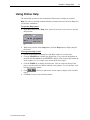


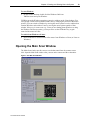
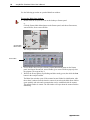
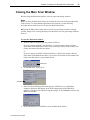
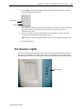

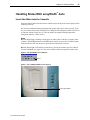

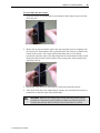
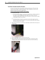


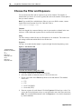
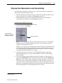


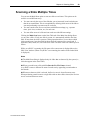
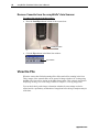


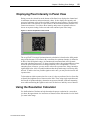


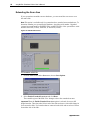
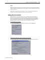
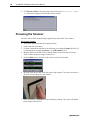

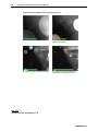


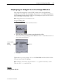
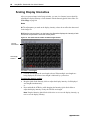


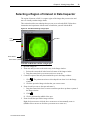
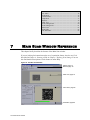


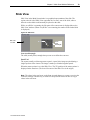
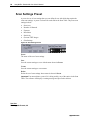

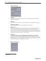


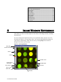


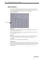
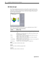

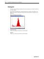
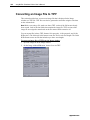

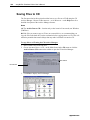


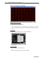
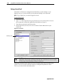

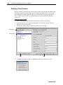
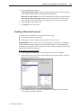

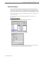
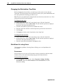


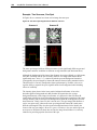


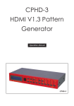


![User's Guide [Advanced Scan Operations]](http://vs1.manualzilla.com/store/data/006865872_1-8b3a85e3ed58d035968500e47824ff56-150x150.png)