1
Océ VarioLink 2221 VarioLink 2821 VarioLink 3621 The road to efficiency User’s Guide Advanced Scan Operations SU-501 Océ-Technologies B.V. Copyright 2008,Océ-Technologies B.V. Venlo, The Netherlands. All rights reserved. No part of this work may be reproduced, copied, adapted, or transmitted in any form or by any means without written permission from Océ. Océ-Technologies B.V. makes no representation or warranties with respect to the contents hereof and specifically disclaims any implied warranties of merchantability or fitness for any particular purpose. Further, Océ-Technologies B.V. reserves the right to revise this publication and to make changes from time to time in the content hereof without obligation to notify any person of such revision or changes. Edition 2009-02 GB Contents 1 2 Introduction 1.1 Energy Star® ..................................................................................... 1-4 What is an ENERGY STAR® Product? .......................................... 1-4 1.2 Trademarks and registered trademarks......................................... 1-5 License information........................................................................ 1-5 OpenSSL Statement ...................................................................... 1-6 1.3 About this manual............................................................................. 1-9 Structure of the manual ................................................................. 1-9 Notations........................................................................................ 1-9 Images that are used ................................................................... 1-10 Function precautions ................................................................... 1-10 Functions that cannot be used .................................................... 1-10 1.4 User manuals .................................................................................. User manual [Copy Operations]................................................... User manual [Network Scanner Operations]................................ User manual [Box Operations] ..................................................... User manual [Print Operations] .................................................... User manual [Advanced Scan Operations] (this manual)............. User manual [Facsimile Operations] ............................................ 1-12 1-12 1-12 1-12 1-12 1-12 1-12 1.5 Explanation of manual conventions.............................................. Safety advices.............................................................................. Sequence of action ...................................................................... Tips .............................................................................................. Special text markings................................................................... 1-13 1-13 1-13 1-14 1-14 Features 2.1 IP address faxing .............................................................................. 2-3 2.2 Scan to PC......................................................................................... 2-4 2.3 IP Scanner ......................................................................................... 2-5 2.4 IP Relay.............................................................................................. 2-6 2.5 Web Connection ............................................................................... 2-7 VarioLink 2221/2821/3621 Contents-1 3 IP address faxing 3.1 Specifying a recipient with a one-touch dial button ...................... 3-3 Selecting a one-touch dial button................................................... 3-3 Specifying a recipient by touching a one-touch dial button ........... 3-3 Entering the number of the one-touch dial button ......................... 3-5 Searching for a one-touch recipient ............................................... 3-7 3.2 Entering an address .......................................................................... 3-9 To enter an address ........................................................................ 3-9 3.3 Specifying the scanning quality and zoom ratio .......................... 3-12 Quality ........................................................................................... 3-12 To select an Quality setting .......................................................... 3-13 Density .......................................................................................... 3-14 To select a Density setting............................................................ 3-14 Original Size Setting...................................................................... 3-15 3.4 Specifying additional functions...................................................... 3-16 Specifying the transmission source information........................... 3-18 Specifying the transmission report printing condition .................. 3-20 Specifying 2in1 transmission ........................................................ 3-21 Specifying double-sided transmission settings ............................ 3-22 Specifying priority transmission.................................................... 3-23 Specifying timer transmission settings ......................................... 3-23 Specifying the stamp setting ........................................................ 3-25 3.5 If the transmission could not be completed ................................. 3-26 Viewing the transmission report ................................................... 3-26 Resending ..................................................................................... 3-27 3.6 Receiving an IP address fax ........................................................... 3-28 3.7 Adding a recipient ........................................................................... 3-29 To program a one-touch dial button............................................. 3-31 Changing/deleting a one-touch dial button .................................. 3-34 Copying a one-touch dial button .................................................. 3-35 Registering/editing/deleting the secondary recipient ................... 3-36 Naming an index ........................................................................... 3-37 To name an index ......................................................................... 3-37 Registering a mail program........................................................... 3-39 To register a mail program............................................................ 3-41 Changing/deleting a mail program ............................................... 3-44 Contents-2 VarioLink 2221/2821/3621 4 Scan to PC operations 4.1 Before saving .................................................................................... 4-3 Installing IP Scanner on the computer........................................... 4-3 Checking the network settings ...................................................... 4-3 4.2 Specifying a destination with a one-touch dial button ................. Selecting a one-touch dial button.................................................. Specifying a recipient by touching a one-touch dial button .......... Entering the number of the one-touch dial button......................... Searching for a one-touch recipient .............................................. 4.3 Entering an address ....................................................................... 4-11 To enter an address ..................................................................... 4-11 4.4 Specifying the scanning quality and zoom ratio.......................... Quality .......................................................................................... To select an Quality setting.......................................................... Density ......................................................................................... To select a Density setting........................................................... Original Size Setting..................................................................... 4-14 4-14 4-15 4-16 4-16 4-17 4.5 Specifying additional functions ..................................................... Specifying the transmission report printing condition ................. Specifying 2in1 transmission ....................................................... Specifying double-sided transmission settings ........................... Specifying priority transmission ................................................... Specifying timer transmission settings ........................................ Specifying the stamp setting ....................................................... Specifying the file name............................................................... 4-18 4-20 4-21 4-22 4-24 4-25 4-26 4-27 4.6 If the data could not be saved ....................................................... 4-28 Viewing the transmission report................................................... 4-28 Resending .................................................................................... 4-29 4.7 Registering a destination ............................................................... Programming a one-touch dial button......................................... To program a one-touch dial button ............................................ Changing/deleting a one-touch dial button ................................. Copying a one-touch dial button ................................................. Registering/editing/deleting the secondary recipient .................. VarioLink 2221/2821/3621 4-4 4-4 4-5 4-7 4-9 4-30 4-30 4-32 4-35 4-36 4-37 Contents-3 5 IP Scanner 5.1 Before using IP Scanner ................................................................... 5-3 IP Scanner and ImageReceiver ...................................................... 5-3 Using a dial-up router ..................................................................... 5-4 Using a modem or terminal adapter ............................................... 5-4 Using Windows XP Service Pack 2/Windows Vista........................ 5-4 Allowing ImageReceiver to be used ............................................... 5-6 ImageReceiver port conflicts .......................................................... 5-7 SSL transmissions .......................................................................... 5-8 Installing certificates ..................................................................... 5-10 5.2 Installing/uninstalling utilities......................................................... 5-13 ImageReceiver installation methods............................................. 5-13 Installing utilities............................................................................ 5-14 Uninstalling utilities (for Windows 2000/XP/Server 2003)............. 5-17 5.3 IP Scanner operations..................................................................... 5-19 Main window................................................................................. 5-19 Available commands..................................................................... 5-21 Scanner Settings dialog box......................................................... 5-23 Sort Settings dialog box (Scanner tab) ......................................... 5-25 Sort Settings dialog box (RX Document tab) ................................ 5-26 Sort Settings dialog box (TX Document tab) ................................ 5-27 Divided Settings dialog box .......................................................... 5-29 Receive Notify Settings dialog box............................................... 5-30 ViewWindow ................................................................................. 5-32 Printer Setting dialog box ............................................................. 5-33 Print Property dialog box .............................................................. 5-34 5.4 ImageReceiver operations.............................................................. 5-36 ImageReceiver icon ...................................................................... 5-36 ImageReceiver commands ........................................................... 5-37 Automatic Print Settings dialog box ............................................. 5-40 Folder and Printer Settings dialog box ......................................... 5-41 5.5 Registering scan buttons and scan operations............................ 5-42 General operation ......................................................................... 5-42 Starting IP Scanner ....................................................................... 5-42 Registering a scan button............................................................. 5-43 Scanning a document using the registered settings .................... 5-46 Viewing the scanned image .......................................................... 5-48 Specifying automatic printing with IP Scanner............................. 5-49 Automatically printing with IP Scanner ......................................... 5-52 Specifying automatic printing with ImageReceiver....................... 5-53 Automatically printing using a one-touch dial button ................... 5-56 Exiting IP Scanner......................................................................... 5-56 Contents-4 VarioLink 2221/2821/3621 5.6 6 Other operations............................................................................. 5-57 Forwarding a received document to IP Scanner ......................... 5-57 Forwarding to IP Scanner ............................................................ 5-58 IP Relay operations 6.1 Before transmitting........................................................................... 6-3 Setting “Gateway TX” to “Restrict”................................................ 6-3 Specifying settings for relay stations ............................................. 6-3 6.2 Specifying a recipient with a one-touch dial button ..................... 6-4 Selecting a one-touch dial button.................................................. 6-4 Specifying a recipient by touching a one-touch dial button .......... 6-5 Entering the number of the one-touch dial button......................... 6-7 Searching for a one-touch recipient .............................................. 6-9 Specifying chain dialing ............................................................... 6-11 6.3 Entering a fax number .................................................................... 6-12 To enter a fax number.................................................................. 6-12 6.4 Specifying the scanning quality and zoom ratio.......................... Quality .......................................................................................... To select an Quality setting.......................................................... Density ......................................................................................... To select a Density setting........................................................... Original Size Setting..................................................................... 6-15 6-15 6-16 6-17 6-17 6-18 6.5 Specifying additional functions ..................................................... Specifying the transmission report printing condition ................. Specifying 2in1 transmission ....................................................... Specifying double-sided transmission settings ........................... Specifying the priority transmission setting ................................. Specifying timer transmission settings ........................................ Specifying the stamp setting ....................................................... 6-19 6-21 6-22 6-23 6-25 6-26 6-27 6.6 If the transmission could not be completed ................................ 6-28 Viewing the transmission report................................................... 6-28 Resending .................................................................................... 6-29 6.7 Registering a recipient ................................................................... Programming a one-touch dial button......................................... To program a one-touch dial button ............................................ Changing/deleting a one-touch dial button ................................. Copying a one-touch dial button ................................................. Registering/editing/deleting the secondary recipient .................. VarioLink 2221/2821/3621 6-30 6-30 6-32 6-35 6-36 6-37 Contents-5 7 8 Specifying settings using Web Connection 7.1 Settings that can be specified using Web Connection ................................................................................ 7-3 Scan tab (User mode) ..................................................................... 7-3 Network tab (Administrator mode).................................................. 7-4 7.2 Using Web Connection ..................................................................... 7-5 System requirements...................................................................... 7-5 Accessing Web Connection............................................................ 7-6 If user authentication settings have been applied .......................... 7-7 If account track settings have been applied ................................... 7-7 Structure of pages .......................................................................... 7-8 Logging on to Administrator mode ............................................... 7-10 Web browser cache ...................................................................... 7-12 With Internet Explorer ................................................................... 7-12 With Netscape .............................................................................. 7-12 7.3 One-Touch Key Registration (User mode) .................................... 7-13 Naming an index ........................................................................... 7-17 Registering a one-touch dial recipient .......................................... 7-19 Registering a secondary recipient ................................................ 7-21 To regist a secondary recipient .................................................... 7-22 Changing the settings for a one-touch dial recipient.................... 7-25 Deleting a one-touch dial recipient ............................................... 7-27 7.4 IP Relay Settings (Administrator mode) ........................................ 7-29 Selecting the IP relay station to be used ...................................... 7-29 To select a relay station ................................................................ 7-30 Registering an IP relay station ...................................................... 7-32 To register an IP relay station ....................................................... 7-33 Specifying management settings 8.1 Available parameters ........................................................................ 8-3 Parameters that can be specified from the Administrator Management screen ....................................................................... 8-3 List of required network settings .................................................... 8-3 8.2 IP Relay Settings ............................................................................... 8-6 Registering an IP relay station ........................................................ 8-6 To register an IP relay station ......................................................... 8-6 Selecting an IP relay station ........................................................... 8-9 Specifying the relay result port ..................................................... 8-10 Contents-6 VarioLink 2221/2821/3621 8.3 9 Specifying software switch settings (machine functions) .......... Software SW settings................................................................... To specify a software switch setting............................................ Specifying settings to limit dialing and broadcast transmissions (mode 018) ............................................................ Specifying settings for the image in the results report (mode 023) ................................................................................... Specifying settings for checked receiver transmissions (mode 200) ................................................................................... Specifying transmission source information for direct faxing and IP address faxing (mode 351) .................................... Specifying whether transmission source information is added when directly faxing, performing an IP relay operation, or forwarding received documents (mode 352) ........................... Specifying the default address input screen (mode 366) ............ Specifying settings for the information indicated in the report for direct faxing/IP relay transmissions (mode 368)..................... Specifies the coding method for IP relay transmissions (mode 381) ................................................................................... Specifying settings concerning the transmission results for IP relay transmissions (mode 382) ............................................... Specifying settings to limit the use of communication modes–1(mode 475) .................................................................... Specifying settings to limit the use of communication modes–2 (mode 476) ................................................................... Specifying settings to limit the use of communication modes– 3/Specifying restrictions for registering fax addresses and printing reports and specifying how one-touch dial recipients are displayed (mode 477)............................................................. Specifying the deleting method for [Del.] in input screens (mode 478) ................................................................................... Specifying settings for limiting user authentication to only Scan functions (mode 479) ................................................................... 8-11 8-11 8-13 8-15 8-16 8-17 8-19 8-20 8-21 8-22 8-23 8-24 8-26 8-28 8-30 8-32 8-33 Troubleshooting 9.1 When a certain screen appears ...................................................... 9-3 9.2 Error codes........................................................................................ Scan to PC operations................................................................... IP Scanner operations.................................................................... IP relay operations ......................................................................... VarioLink 2221/2821/3621 9-4 9-4 9-5 9-6 Contents-7 9.3 Troubleshooting ................................................................................ 9-7 IP address faxing ............................................................................ 9-7 Scan to PC operations.................................................................... 9-8 IP Scanner operations .................................................................... 9-9 IP relay operations and others ...................................................... 9-14 10 Appendix 10.1 Specifications .................................................................................. 10-3 IP address faxing specifications ................................................... 10-3 Scan to PC specifications............................................................. 10-3 IP Scanner specifications ............................................................. 10-4 IP relay specifications ................................................................... 10-4 10.2 Entering text..................................................................................... 10-5 To type text ................................................................................... 10-5 List of available characters ........................................................... 10-6 10.3 Glossary............................................................................................ 10-7 10.4 Index ............................................................................................... 10-11 Contents-8 VarioLink 2221/2821/3621 1 Introduction Introduction 1 1 Introduction Thank you for choosing this machine. This user manual contains details on the operations required to use the advanced Scan functions of the VarioLink 2221, 2821 and 3621, precautions on their use, and basic troubleshooting procedures. In order to ensure that these machines are used correctly and efficiently, carefully read this user manual before using the machine. After reading the user manual, store it in the user manual holder so that it can easily be referred to when questions or problems arise during operation. Views of the actual equipment may be slightly different from the illustrations used in this user manual. VarioLink 2221/2821/3621 1-3 Introduction 1 1.1 Energy Star® As an ENERGY STAR® Partner, we have determined that this machine meets the ENERGY STAR® Guidelines for energy efficiency. What is an ENERGY STAR® Product? An ENERGY STAR® product has a special feature that allows it to automatically switch to a "low-power mode" after a period of inactivity. An ENERGY STAR® product uses energy more efficiently, saves you money on utility bills and helps protect the environment. 1-4 VarioLink 2221/2821/3621 Introduction 1.2 1 Trademarks and registered trademarks Netscape Communications, the Netscape Communications logo, Netscape Navigator, Netscape Communicator, and Netscape are trademarks of Netscape Communications Corporation. Compact-VJE Copyright 1986-2003 VACS Corp. RC4® is a registered trademark or trademark of RSA Security Inc. in the United States and/or other countries. RSA® is a registered trademark or trademark of RSA Security Inc. RSA BSAFE® is a registered trademark or trademark of RSA Security Inc. in the United States and/or other countries. License information This product includes RSA BSAFE Cryptographic software from RSA Security Inc. VarioLink 2221/2821/3621 1-5 Introduction 1 OpenSSL Statement OpenSSL License Copyright © 1998-2000 The OpenSSL Project. All rights reserved. Redistribution and use in source and binary forms, with or without modification, are permitted provided that the following conditions are met: 1. Redistributions of source code must retain the above copyright notice, this list of conditions and the following disclaimer. 2. Redistributions in binary form must reproduce the above copyright notice, this list of conditions and the following disclaimer in the documentation and/or other materials provided with the distribution. 3. All advertising materials mentioning features or use of this software must display the following acknowledgment: "This product includes software developed by the OpenSSL Project for use in the OpenSSL Toolkit. (http://www.openssl.org/)" 4. The names "OpenSSL Toolkit" and "OpenSSL Project" must not be used to endorse or promote products derived from this software without prior written permission. For written permission, please contact [email protected]. 5. Products derived from this software may not be called "OpenSSL" nor may "OpenSSL" appear in their names without prior written permission of the OpenSSL Project. 6. Redistributions of any form whatsoever must retain the following acknowledgment: "This product includes software developed by the OpenSSL Project for use in the OpenSSL Toolkit (http://www.openssl.org/)" THIS SOFTWARE IS PROVIDED BY THE OpenSSL PROJECT "AS IS" AND ANY EXPRESSED OR IMPLIED WARRANTIES, INCLUDING, BUT NOT LIMITED TO, THE IMPLIED WARRANTIES OF MERCHANTABILITY AND FITNESS FOR A PARTICULAR PURPOSE ARE DISCLAIMED. IN NO EVENT SHALL THE OpenSSL PROJECT OR ITS CONTRIBUTORS BE LIABLE FOR ANY DIRECT, INDIRECT, INCIDENTAL, SPECIAL, EXEMPLARY, OR CONSEQENTIAL DAMAGES (INCLUDING, BUT NOT LIMITED TO, PROCUREMENT OF SUBSTITUTE GOODS OR SERVICES; LOSS OF USE, DATA, OR PROFITS; OR BUSINESS INTERRUPTION) HOWEVER CAUSED AND ON ANY THEORY OF LIABILITY, WHETHER IN CONTRACT, STRICT LIABILITY, OR TORT (INCLUDING NEGLIGENCE OR OTHERWISE) ARISING IN ANY WAY OUT OF THE USE OF THIS SOFTWARE, EVEN IF ADVISED OF THE POSSIBILITY OF SUCH DAMAGE. This product includes cryptographic software written by Eric Young ([email protected]). This product includes software written by Tim Hudson ([email protected]). 1-6 VarioLink 2221/2821/3621 Introduction 1 Original SSLeay License Copyright © 1995-1998 Eric Young ([email protected]) All rights reserved. This package is an SSL implementation written by Eric Young ([email protected]). The implementation was written so as to conform with Netscape’s SSL. This library is free for commercial and non-commercial use as long as the following conditions are adhered to. The following conditions apply to all code found in this distribution, be it the RC4, RSA, Ihash, DES, etc., code; not just the SSL code. The SSL documentation included with this distribution is covered by the same copyright terms except that the holder is Tim Hudson ([email protected]). Copyright remains Eric Young’s, and as such any Copyright notices in the code are not to be removed. If this package is used in a product, Eric Young should be given attribution as the author of the parts of the library used. This can be in the form of a textual message at program startup or in documentation (online or textual) provided with the package. Redistribution and use in source and binary forms, with or without modification, are permitted provided that the following conditions are met: 1. Redistributions of source code must retain the copyright notice, this list of conditions and the following disclaimer. 2. Redistributions in binary form must reproduce the above copyright notice, this list of conditions and the following disclaimer in the documentation and/or other materials provided with the distribution. 3. All advertising materials mentioning features or use of this software must display the following acknowledgement: "This product includes cryptographic software written by Eric Young ([email protected])" The word ‘cryptographic’ can be left out if the routines from the library being used are not cryptographic related. 4. If you include any Windows-specific code (or a derivative thereof) from the apps directory (application code) you must include an acknowledgement: "This product includes software written by Tim Hudson ([email protected])" THIS SOFTWARE IS PROVIDED BY ERIC YOUNG "AS IS" AND ANY EXPRESS OR IMPLIED WARRANTIES, INCLUDING, BUT NOT LIMITED TO, THE IMPLIED WARRANTIES OF MERCHANTABILITY AND FITNESS FOR A PARTICULAR PURPOSE ARE DISCLAIMED. IN NO EVENT SHALL THE AUTHOR OR CONTRIBUTORS BE LIABLE FOR ANY DIRECT, INDIRECT, INCIDENTAL, SPECIAL, EXEMPLARY, OR CONSEQUENTIAL DAMAGES (INCLUDING, BUT NOT LIMITED TO, PROCUREMENT OF SUBSTITUTE GOODS OR SERVICES; LOSS OF USE, DATA, OR PROFITS; OR BUSINESS INTERRUPTION) HOWEVER CAUSED AND ON ANY THEORY OF LIABILITY, WHETHER IN CONTRACT, STRICT LIABILITY, OR TORT VarioLink 2221/2821/3621 1-7 1 Introduction (INCLUDING NEGLIGENCE OR OTHERWISE) ARISING IN ANY WAY OUT OF THE USE OF THIS SOFTWARE, EVEN IF ADVISED OF THE POSSIBILITY OF SUCH DAMAGE. The licence and distribution terms for any publicly available version or derivative of this code cannot be changed, i.e., this code cannot simply be copied and put under another distribution licence [including the GNU Public Licence.] All other product names mentioned are trademarks or registered trademarks of their respective companies. Information carried in this manual including design and related materials, and software contained in the machine and software attached to the CD-ROM are valuable assets of NEC, NEC AccessTechnica, Ltd. and respective licensee(s). NEC, NEC AccessTechnica, Ltd. and the licensee shall reserve all rights to design, produce, copy, use and sell this manual, including the patents, copyrights, and other proprietary rights, except when such an action is permitted to be transferred to another company with a written consent. 1-8 VarioLink 2221/2821/3621 Introduction 1.3 1 About this manual This user manual covers the functions that are added when the scanner unit is installed on the VarioLink 2221, 2821 and 3621. This section introduces the structure of the manual and the notations used for product names, etc. This manual is intended for users who understand the basic operations of computers and this machine. For operating procedures of the Windows or Macintosh operating system and software applications, refer to the corresponding manuals. Structure of the manual This manual consists of the following chapters. Chapter 1 Introduction Chapter 2 Features Chapter 3 IP address faxing Chapter 4 Scan to PC operations Chapter 5 IP Scanner Chapter 6 IP Relay operations Chapter 7 IP Relay operations Chapter 8 Specifying management settings Chapter 9 Troubleshooting Chapter 10 Appendix Notations Product Name Notation in the Manual VarioLink 2221/2821/3621 this machine or this device or VarioLink 2221/2821/3621 Internal network controller Printer controller Microsoft Windows NT 4.0 Windows NT 4.0 Microsoft Windows 2000 Windows 2000 Microsoft Windows XP Windows XP Microsoft Windows Vista Windows Vista Microsoft Windows Server 2003 Windows Server 2003 Microsoft Windows Server 2008 Windows Server 2008 When the operating systems listed above are all written together Windows NT 4.0/2000/XP VarioLink 2221/2821/3621 1-9 Introduction 1 Images that are used Generally, the touch panel screens and application windows that appear in this manual show that only the optional scanner unit has been installed. Function precautions Follow the precautions listed below when using these functions. - Since the privacy of transmissions through the Internet or an intranet is limited, we recommend sending important documents directly to the recipient through a common telephone line. - Telephones on a LAN cannot be used. - It may take some time for a transmission to be sent due to Internet/intranet traffic. - Depending on the mail servers, it may not be possible to send documents with a large number of pages or a large amount of image data. Functions that cannot be used The following functions can be used with normal fax transmissions using a common telephone line, but cannot be used if only the scanner unit is installed. - Batch transmission - Polling reception - Polling transmission - Quick scan transmission - Password transmission - Remote copying - Confidential box transmissions - Bulletin registration - On-hook dialing - Remote bulletin retrieval - "No Reduction" setting 2 Note Password transmission and remote copying can be specified in the operation, but they will not function. 1-10 VarioLink 2221/2821/3621 Introduction 1 The following functions can be used. - Quality settings - Density settings - Original Size Setting - Transmission report - 2in1 - Double-sided transmission - Stamp (optional) - Transmission source information* - Priority transmission - Timer transmission - Rotation transmission* *Functions that can be used with Internet faxing and IP address faxing VarioLink 2221/2821/3621 1-11 Introduction 1 1.4 User manuals The following user manuals have been prepared for this machine. User manual [Copy Operations] This manual contains details on basic operations and the operating procedures for the various copy functions. - Refer to this user manual for details on operating procedures for copy functions, including precautions on installation/use, turning the machine on/off, loading paper, and troubleshooting operations such as clearing paper misfeeds. User manual [Network Scanner Operations] This manual contains details on specifying network functions for standard equipment and on operations for scanning functions. - Refer to this user manual for details on operating procedures for network functions and for using the Scan to E-Mail, Scan to FTP, Scan to SMB and Internet fax operations. User manual [Box Operations] This manual contains details on operating procedures for using the Box functions. - Refer to this user manual for details on printing a proof copy or a locked job and on functions that use the optional hard disk drive, such as routing and saving documents in boxes. User manual [Print Operations] This manual contains details on operating procedures using the standard built-in printer controller. - For details on the printing functions, refer to user manual (PDF file) on User Software CD-ROM. User manual [Advanced Scan Operations] (this manual) This manual contains details on the operating procedures for the functions that can be used when the optional scanner unit is installed. - Refer to this user manual for details on using the IP address faxing, IP Relay and Scan to PC operations and on using IP Scanner. User manual [Facsimile Operations] This manual contains details on operating procedures for using the Fax functions. - Refer to this user manual for details on operating procedures for the Fax functions when the fax kit is installed. 1-12 VarioLink 2221/2821/3621 Introduction 1.5 1 Explanation of manual conventions The marks and text formats used in this manual are described below. Safety advices 6 DANGER Failure to observe instructions highlighted in this manner may result in fatal or critical injuries in fact of electrical power. % Observe all dangers in order to prevent injuries. 7 WARNING Failure to observe instructions highlighted in this manner may result in serious injuries or property damage. % Observe all warnings in order to prevent injuries and to ensure safe use of the copier. 7 CAUTION Failure to observe instructions highlighted in this manner may result in slight injuries or property damage. % Observe all cautions in order to prevent injuries and to ensure safe use of the copier. Sequence of action 1 The number 1 as formatted here indicates the first step of a sequence of actions. 2 Subsequent numbers as formatted here indicate subsequent steps of a sequence of actions. An illustration inserted here shows what operations must be performed. Text formatted in this style provides additional assistance. % Text formatted in this style describes the action that will ensure the desired results are achieved. ? VarioLink 2221/2821/3621 1-13 Introduction 1 Tips 2 Note Text highlighted in this manner contains useful information and tips to ensure safe use of the copier. 2 Reminder Text highlighted in this manner contains information that should be reminded. ! Detail Text highlighted in this manner contains references for more detailed information. Special text markings [Copy] key The names of keys on the control panel are written as shown above. MACHINE SETTING Display texts are written as shown above. 1-14 VarioLink 2221/2821/3621 2 Features Features 2 2 Features 2.1 IP address faxing Scan data is sent through the Intranet, without passing though a mail server on the network. The data can only be received by a machine of the same type as this one and set up to receive IP address faxes. - This machine must be connected to a LAN and the network settings must be specified. For details on specifying the network settings, refer to the User manual [Network Scanner Operations]. For network settings related to this machine, refer to "Available parameters" on page 8-3. - If a destination is registered with a one-touch dial button, a transmission can be sent simply by touching the one-touch dial button. - For details, refer to chapter 2, "IP address faxing" on page 3-3. IP address Fax terminal (Same type of unit as this machine) Intranet VarioLink 2221/2821/3621 2-3 Features 2 2.2 Scan to PC Scan data is sent to the specified computer on the network and saved in a folder that has already been set up. This allows paper documents to be saved as electronic data simply with the touch a button, even in an environment where a mail server is not used. Using the included IP Scanner and ImageReceiver utilities, the folder where the data is to be saved must be specified in advance on the computer receiving the data. In addition, depending on the settings specified in IP Scanner, a folder can be created with the name of the one-touch button and the data can be saved in it. - The document is sent as a TIFF or PDF image file. - TIFF image files can be viewed on Windows with the included Tiff Viewer. - PDF image files can be viewed with Adobe Reader. - Even in an environment that does not have a LAN, a crossover cable can be used to directly connect this machine to the computer so that the Scan to PC operation can be used. - If there is a DHCP server on the network, this function may not operate correctly since IP addresses are automatically assigned to each computer. In this case, specify a fixed IP address for the computer or use IP Scanner to save the data. - This machine must be connected to a LAN and the network settings must be specified. For details on specifying the network settings, refer to the User manual [Network Scanner Operations]. For network settings related to this machine, refer to "Available parameters" on page 8-3. - For details, refer to chapter 3, "Scan to PC operations" on page 4-3. Client computer Intranet 2-4 VarioLink 2221/2821/3621 Features 2.3 2 IP Scanner Scan data is sent to the specified computer on the network, and the data is saved in a folder created with the same name as the registered scan button. From the computer, register scan settings as a scan button on this machine to save paper documents as electronic data simply by touching the scan button. - The document is sent as a TIFF or PDF image file. - TIFF image files can be viewed on Windows with the included Tiff Viewer. - PDF image files can be viewed with Adobe Reader. - Even in an environment that does not have a LAN, a crossover cable can be used to directly connect this machine to the computer so that IP Scanner can be used. - This machine must be connected to a LAN and the network settings must be specified. For details on specifying the network settings, refer to the User manual [Network Scanner Operations]. For network settings related to this machine, refer to "Available parameters" on page 8-3. - For details, refer to chapter 4, "IP Scanner" on page 5-3. - Documents sent as a fax transmission or as an Internet fax can also be forwarded to the computer specified in IP Scanner by the administrator. Client computer Scan settings VarioLink 2221/2821/3621 2-5 Features 2 2.4 IP Relay A fax is sent through a relay machine connected to the LAN. If one relay machine is connected to a telephone line in an intranet, specify the relay machine from the machines (this machine) connected to the LAN to send a fax using the telephone line. The results of the relayed fax transmission can be checked from the machine that sent the fax transmission. - This machine must be connected to a LAN and the network settings must be specified. For details on specifying the network settings, refer to the User manual [Network Scanner Operations]. For network settings related to this machine, refer to "Available parameters" on page 8-3. - If a destination is registered with a one-touch dial button, a transmission can be sent simply by touching the one-touch dial button. - For details, refer to chapter 5, "IP Relay operations" on page 6-3. Fax Fax terminal transmission Telephone line Relay machine Machine sending the command 2-6 VarioLink 2221/2821/3621 Features 2.5 2 Web Connection The computer can be used to check the machine transmission/printing status and whether or not the fax is printed. In addition, various items can be registered, such as one-touch buttons. Web Connection has a mode for operations performed by general users and a mode for operations performed by the administrator. - This machine must be connected to a LAN and the network settings must be specified. For details on specifying the network settings, refer to the User manual [Network Scanner Operations]. - For details, refer to chapter 6, "Specifying settings using Web Connection" on page 7-3. VarioLink 2221/2821/3621 2-7 2 2-8 Features VarioLink 2221/2821/3621 3 IP address faxing IP address faxing 3 3 IP address faxing 3.1 Specifying a recipient with a one-touch dial button If the IP address of a recipient is registered with a one-touch dial button, data can be sent simply by touching the one-touch dial button. In addition, other transmission functions can be added or a mail program can be registered. For details on registering a one-touch dial button or a mail program, refer to "Adding a recipient" on page 3-29. Selecting a one-touch dial button A one-touch dial button can selected in any of the following ways. Use the appropriate method according to the number of recipients and the desired use. - Directly touching the one-touch dial button - Entering the number of the one-touch dial button - Searching for the name of a recipient Specifying a recipient by touching a one-touch dial button 1 Position the document to be scanned. 2 Press the [Fax/Scan] key. – 3 The screen that appears after the [Fax/Scan] key is pressed can be specified using the "Default Screen" parameter in the User’s Choice screen. For details, refer to the User manual [Copy Operations]. Touch [One-Touch]. VarioLink 2221/2821/3621 3-3 IP address faxing 3 4 Select the index containing the desired recipient, and then touch the one-touch dial button. – – – 5 Specify the appropriate settings on the Quality & Reduction tab according to the document to be sent. – 6 – 3-4 For details, refer to "Specifying the scanning quality and zoom ratio" on page 3-12. Specify the necessary settings on the Menu tab. – 7 Multiple recipients can be specified for simultaneous transmission with the same onetouch dial button. A maximum of 300 recipients can be specified with a single one-touch dial button. To select an index, touch the tab of the desired index, or touch or to select a different tab. If software switch settings were specified to prevent broadcast transmissions, a fax cannot be sent to multiple recipients. For details on the software switch settings, refer to "Specifying software switch settings (machine functions)" on page 8-11. If the optional fax kit has been installed, specify the necessary settings on the FAX Menu tab. For details, refer to "Specifying additional functions" on page 3-16. Press the [Start] key. VarioLink 2221/2821/3621 IP address faxing 3 Entering the number of the one-touch dial button Each one-touch dial button is assigned a number, as shown below. Instead of touching a one-touch dial button, specifying the number of the one-touch dial button allows a recipient to quickly be selected. Index 1 1 Position the document to be scanned. 2 Press the [Fax/Scan] key. 3 Press the [#] key in the control panel. VarioLink 2221/2821/3621 Index 36 3-5 IP address faxing 3 4 Using the keypad, type in the number of the one-touch dial button. – – – 5 Specify the appropriate settings on the Quality & Reduction tab according to the document to be sent. – 6 – 3-6 For details, refer to "Specifying the scanning quality and zoom ratio" on page 3-12. Specify the necessary settings on the Menu tab. – 7 The specified one-touch dial button is highlighted. Multiple recipients can be specified for simultaneous transmission with the same onetouch dial button. A maximum of 300 recipients can be specified with a single one-touch dial button. If software switch settings were specified to prevent broadcast transmissions, a fax cannot be sent to multiple recipients. For details on the software switch settings, refer to "Specifying software switch settings (machine functions)" on page 8-11. If the optional fax kit has been installed, specify the necessary settings on the FAX Menu tab. For details, refer to "Specifying additional functions" on page 3-16. Press the [Start] key. VarioLink 2221/2821/3621 IP address faxing 3 Searching for a one-touch recipient The name of a recipient registered with a one-touch dial button can be searched for in order to select the one-touch dial button. 1 Position the document to be scanned. 2 Press the [Fax/Scan] key. 3 Touch [Search]. – 4 If an LDAP search is possible, touch [LDAP Search] to search further. Type in the name of the recipient, and then touch [Search]. A screen appears, containing the list of one-touch dial buttons programmed with a recipient whose name begins with the entered name. 5 Touch the desired one-touch dial button to select it. – – Multiple recipients can be specified for simultaneous transmission with the same onetouch dial button. A maximum of 300 recipients can be specified with a single one-touch dial button. If software switch settings were specified to prevent broadcast transmissions, a fax cannot be sent to multiple recipients. For details on the software switch settings, refer to "Specifying software switch settings (machine functions)" on page 8-11. VarioLink 2221/2821/3621 3-7 IP address faxing 3 6 Specify the appropriate settings on the Quality & Reduction tab according to the document to be sent. – 7 Specify the necessary settings on the Menu tab. – – 8 3-8 For details, refer to "Specifying the scanning quality and zoom ratio" on page 3-12. If the optional fax kit has been installed, specify the necessary settings on the FAX Menu tab. For details, refer to "Specifying additional functions" on page 3-16. Press the [Start] key. VarioLink 2221/2821/3621 IP address faxing 3.2 3 Entering an address The address of a recipient not registered in a one-touch dial button can be entered directly to be specified. 2 Note If software switch settings were specified to limit dialing, a fax cannot be sent by directly typing in the address. For details on the software switch settings, refer to "Specifying software switch settings (machine functions)" on page 8-11. To enter an address 1 Position the document to be scanned. 2 Press the [Fax/Scan] key. 3 Touch [Direct Input]. 4 Select the communication mode. Touch [Change Comm. Mode]. VarioLink 2221/2821/3621 3-9 IP address faxing 3 5 Touch [InternetFAX], then [IP-TX], and then touch [Enter]. 6 Type in the IP address of the recipient machine. – – 7 To select the maximum transmission size and coding method, touch [E-Mail Mode]. 8 On the E-Mail Mode screen, settings can be specified for the following. Select the desired settings, and then touch [Enter]. – – – 3-10 If a DNS server is specified from the Network Setting screen, the host name can be typed in. Touch [Host], and then type in the host name. To change the entered address, press the [C] (clear) key, and then enter the correct address. TX Size (Max.): Specify the maximum document size that can be transmitted. Select "Letter/Legal" or "11 x 17". TX Quality (Max.): Select the maximum resolution that can be sent. Select "200dpi", "400dpi" or "600dpi". Coding Method: Select the coding method for the data to be sent. Select "MH", "MR" or "MMR". The data amount for the coding methods increase as follows: MMR, MR, MH. VarioLink 2221/2821/3621 IP address faxing 9 To change the port number, touch [Port]. – – 10 For details, refer to "Specifying the scanning quality and zoom ratio" on page 3-12. Specify the necessary settings on the Menu tab. – – 12 To change the port number, press the [C] (clear) key, use the keypad to type in the port number, and then touch [Enter]. To return to the default setting, touch [Default]. Specify the appropriate settings on the Quality & Reduction tab according to the document to be sent. – 11 3 If the optional fax kit has been installed, specify the necessary settings on the FAX Menu tab. For details, refer to "Specifying additional functions" on page 3-16. Press the [Start] key. VarioLink 2221/2821/3621 3-11 IP address faxing 3 3.3 Specifying the scanning quality and zoom ratio Touch [Quality & Reduction] in the screen that appears when the [Fax/Scan] key is pressed to specify the scanning image quality and zoom ratio. ! Detail When a transmission is finished, the transmission settings return to their defaults. Quality Select the scanning resolution (amount of details). From the following available resolution settings, select the appropriate resolution according to the type of document being scanned. Setting Description Standard For documents with normal text (such as handwriting) Fine Super Fine 600dpi Text For documents containing small print, such as newspapers, or documents containing detailed illustrations Text/Photo 600dpi Text&Photo For documents containing both text and images with color shades (such as photos) GSR Super GSR 600dpi Photo For documents with color shades, such as photos ! Detail If data is sent with the "Text/Photo" setting selected, moire patterns may appear in some photos. This is not a sign of a malfunction. To reduce the appearance of moire patterns, send the data with the "GSR" or "Super GSR" setting. If a high resolution was selected in order to send a clean image, the size of the image data that is sent may become large and the provider or server may not allow the data to be sent. First, check the size limitations for data that can be sent. 3-12 VarioLink 2221/2821/3621 IP address faxing 3 To select an Quality setting 1 Touch [Quality & Reduction]. 2 Touch [Quality], and then touch the button for the desired Quality setting. – To select a higher resolution, touch [600 dpi]. VarioLink 2221/2821/3621 3-13 IP address faxing 3 Density From the following available resolution settings, select the appropriate resolution according to the type of document being scanned. Setting Description Light For documents with a dark background color, such as newspaper and blueprints Std. For normal documents Dark For documents with faint or colored text To select a Density setting 3-14 1 Touch [Quality & Reduction]. 2 Touch [Density], and then touch the button for the desired Density setting. VarioLink 2221/2821/3621 IP address faxing 3 Original Size Setting The scanned area can be specified as a standard size. However, a portion of a large document can be sent or a non-standard-sized document can be sent as a standard size. 1 Touch [Quality & Reduction]. 2 Touch [Reduction/Area], and then touch [Original Size Set.]. 3 Select the desired scanning size, and then touch [Enter]. – Touch [Auto Detect] to automatically select the size closest to the size of the document. However, if the document is smaller than Letter size, Letter size is selected. VarioLink 2221/2821/3621 3-15 IP address faxing 3 3.4 Specifying additional functions Touch [Menu] in the screen that appears when the [Fax/Scan] key is pressed to add the following functions. 2 Note If the optional fax kit has been installed, [Menu] changes to [Fax Menu]. Function Setting 1 tab *(Set 1 tab) Setting 2 tab *(Set 2 tab) Description TSI Select the information, such as this machine’s name, fax number or address or the recipient’s name, that is printed at the edge of the page. For details on registering transmission source information, refer to the User manual [Network Scanner Operations]. If a recipient’s name is selected, the recipient name registered with the one-touch dial button is printed. TX Report Select the conditions for printing the transmission results report. Default: Select this setting to print the report according to the setting specified from the Administrator Management screen. ON: Select this setting to print the report, regardless of the transmission result. If TX Fails: Select this setting to print the report only if the transmission failed. OFF: Select this setting to not print the report, regardless of the transmission result. 2in1 Select whether or not to send the data using the "2in1" function (reducing two pages to fit in a single page). 2-Sided TX Select whether or not a double-sided transmission is performed. The position of the binding margin and the page orientation can also be specified. Rotation TX Select whether or not to rotate the scan image according to the paper orientation of the receiving machine. This function can be specified when sending an A4-size image with a resolution of 200 dpi or less. Priority TX Select whether or not the data is sent with priority over the other jobs. Timer TX Setting Specify the time that the fax is to be sent. Stamp Specify whether the scanned image is stamped to indicated that it has been scanned. The document must be loaded into the ADF. 2 Note In order to use the "Stamp" function, optional stamp unit must be installed. * Changes to ( ) if the optional fax kit has been installed. 3-16 VarioLink 2221/2821/3621 IP address faxing 3 2 Note The following parameters and functions have no effect, even if settings have been specified. - "Subject Selection" on the Network tab - "Reply Address" on the Network tab - "File Name" on the Network tab - "Email Notification" on the Network tab VarioLink 2221/2821/3621 3-17 IP address faxing 3 Specifying the transmission source information Select the information, such as this machine’s name, fax number or address or the recipient’s name, that is printed at the edge of the page. FROM: NEWYORK Image data has been attached to the e-mail. 1 Touch [Menu]. – 2 Touch [TSI] on the Setting 1 tab. – 3-18 If the optional fax kit has been installed, touch [FAX Menu]. If the optional fax kit has been installed, touch [TSI] on the Set 1 tab. 3 Select the print type for the transmission information, and then touch [TSI Selection]. 4 Select the transmission source name, and then touch [Enter]. VarioLink 2221/2821/3621 IP address faxing 5 3 Touch [Enter]. VarioLink 2221/2821/3621 3-19 IP address faxing 3 Specifying the transmission report printing condition The conditions for printing the transmission result report can be specified. The conditions for printing the transmission result report are preset with the "Report Settings" parameters from the Administrator Management 1 screen. Follow the procedure described below to change these conditions. 1 Touch [Menu]. – 2 Touch [TX Report] on the Setting 1 tab. – 3 3-20 If the optional fax kit has been installed, touch [FAX Menu]. If the optional fax kit has been installed, touch [TX Report] on the Set 1 tab. Specify the desired printing condition, and then touch [Enter]. VarioLink 2221/2821/3621 IP address faxing 3 Specifying 2in1 transmission 1 Touch [Menu]. – 2 If the optional fax kit has been installed, touch [FAX Menu]. Touch [2in1] on the Setting 1 tab. – If the optional fax kit has been installed, touch [2in1] on the Set 1 tab. The button is highlighted. To cancel the function, touch the button again to deselect it. VarioLink 2221/2821/3621 3-21 IP address faxing 3 Specifying double-sided transmission settings 1 Touch [Menu]. – 2 If the optional fax kit has been installed, touch [FAX Menu]. Touch [2-Sided TX] on the Setting 1 tab. – 3 If the optional fax kit has been installed, touch [2-Sided TX] on the Set 1 tab. Select the appropriate binding margin position. – – – Left Bind: The document is scanned with a binding margin on the left side. Top Bind: The document is scanned with a binding margin at the top. Auto: The binding margin is set according to the scanning direction. 4 Touch [Original Direction]. 5 Select the orientation of the document, and then touch [Enter]. – 6 Auto: The long side of the document is automatically set as the binding position. Touch [Enter]. – To cancel the function, touch [OFF]. ! Detail When loading a double-sided document with pages of different widths, we recommend loading the pages with the same orientation. When a document with pages of different orientations is scanned, the orientation of the image data may not be correct. 3-22 VarioLink 2221/2821/3621 IP address faxing 3 Specifying priority transmission 1 Touch [Menu]. – 2 If the optional fax kit has been installed, touch [FAX Menu]. Touch [Priority TX] on the Setting 2 tab. – If the optional fax kit has been installed, touch [Priority TX] on the Set 2 tab. The button is highlighted. To cancel the function, touch the button again to deselect it. Specifying timer transmission settings 1 Touch [Menu]. – 2 Touch [Timer TX Setting] on the Setting 2 tab. – 3 If the optional fax kit has been installed, touch [Timer TX Setting] on the Set 2 tab. Specify the time that the transmission is to be sent. – 4 If the optional fax kit has been installed, touch [FAX Menu]. Touch [Hour] or [Minute], and then use the keypad to type in the desired time. Touch [Enter]. – To cancel the function, touch [OFF]. VarioLink 2221/2821/3621 3-23 IP address faxing 3 2 Note Up to 200 documents can be specified with a timer transmission. 3-24 VarioLink 2221/2821/3621 IP address faxing 3 Specifying the stamp setting 1 Touch [Menu]. – 2 Touch [Stamp] on the Setting 2 tab. – 3 If the optional fax kit has been installed, touch [FAX Menu]. If the optional fax kit has been installed, touch [Stamp] on the Set 2 tab. Select the stamping position, and then touch [Enter]. VarioLink 2221/2821/3621 3-25 IP address faxing 3 3.5 If the transmission could not be completed If the transmission could not be completed correctly, a transmission result report is printed. ! Detail The setting for printing the transmission report can be changed. For details, refer to the User manual [Network Scanner Operations]. Viewing the transmission report 2 1 3 4 IMAGE 3-26 5 No. Item Description 1 Report output date Shows the date that the report was printed. 2 Transmission source name Shows the name and address of the transmission source. 3 Transmission information Shows the number for the transmitted document, the time required, and the communication mode. VarioLink 2221/2821/3621 IP address faxing 3 No. Item Description 4 Transmission results Shows the transmission results. Any of the following may be indicated. OK: The transmission was completed successfully. INTERR: The transmission was interrupted. F.MEM: The memory is full. NG: The transmission was completed unsuccessfully. PT.DEL: The transmission to some recipients failed. F.DATA: The size of the data exceeds the allowable limit. IMG NG: The transmission resolution was incorrect so the transmission was ended. Error code: For details, refer to "Error codes" on page 9-4. 5 Transmission image Shows a part of the transmitted image. Resending A maximum of 20 documents that could not be sent are saved to be sent again. 1 Touch [Job List], touch [Type], and then select the document that could not be sent. – 2 If [Retry] or [Change Destination] appears in the screen, the document can be resent without being scanned again. To send the document to the same recipient, touch [Retry]. – To send the document to a different recipient, touch [Change Destination]. VarioLink 2221/2821/3621 3-27 IP address faxing 3 3.6 Receiving an IP address fax If an IP address fax is sent to this machine, it is automatically received and printed. The IP address of this machine must first be specified in the Network Setting screen. ! Detail The reception method specified from the FAX Setting screen (displayed from the Administrator Management 1 screen) is valid only if the fax is received using a general telephone line. This setting is not applied when an IP address fax is received. 3-28 VarioLink 2221/2821/3621 IP address faxing 3.7 3 Adding a recipient If a recipient is registered with a one-touch dial button, the transmission can be sent easily and accurately. Two types of recipients can be registered with a one-touch dial button: a main recipient and a secondary recipient, where the data is sent if the transmission to the main recipient fails. 2 Note If "Restrict One-Touch Editing" on the Administrator Set screen (displayed from the Administrator Management 1 screen) is set to "ON", if software switch settings were specified to limit registration of onetouch dial buttons to the administrator, or if "Enhance Security" is set to "ON", one-touch dial buttons can only be registered, edited or deleted from Administrator mode. For details on the settings in Administrator mode, refer to the User manual [Facsimile Operations]. For details on the software switch settings, refer to "Specifying software switch settings (machine functions)" on page 8-11. ! Detail Any of the following communication modes can be specified for the secondary recipient. - PC (E-Mail) - PC (Scanner) - InternetFAX (Internet FAX) - InternetFAX (IP-TX) - InternetFAX (IP Relay) - FAX (G3)* * The communication mode can be specified if the optional fax kit is installed. 2 Note Certain communication modes may not be available, depending on the machine settings. For details, check with the administrator. VarioLink 2221/2821/3621 3-29 IP address faxing 3 Settings can be specified for the following. Item Description One-Touch Name Type in the name of the recipient that will appear on the one-touch dial button. Up to 12 characters can be entered. Destination Type in the IP address or host name for the recipient. TX Size (Max.) Specify the maximum document size that can be transmitted. Select "Letter/Legal" or "11×17". TX Quality (Max.) Select the maximum resolution that can be sent. Select "200dpi", "400dpi" or "600dpi". Coding Method Select the coding method for the data to be sent. Select "MH", "MR" or "MMR". The data amount for the coding methods increase as follows: MMR, MR, MH. Port Type in the port number (between 1 and 65535). 2 Reminder If the [Utility/Counter] key was pressed to register items and specify settings, be sure to press the [Reset] key in the control panel after returning to the initial screen. 3-30 VarioLink 2221/2821/3621 IP address faxing 3 To program a one-touch dial button 1 Press the [Utility/Counter] key. 2 Touch [User Setting]. 3 Touch [E-Mail Input]. – 4 If the optional fax kit has been installed, touch [FAX]. Touch [One-Touch]. VarioLink 2221/2821/3621 3-31 IP address faxing 3 5 Touch the one-touch dial button to be programmed. – – 6 Type in the recipient name that will appear on the one-touch dial button, and then touch [Next]. 7 Select the communication mode. Touch [InternetFAX], touch [IP-TX], and then touch [Next]. 8 Type in the IP address of the recipient. – – 3-32 Touch an index tab or touch [Index List], and then touch the desired one-touch dial button. If the machine is set to allow LDAP searches, a screen appears, allowing the one-touch dial button to be set to either permit or prohibit the address from being found with an LDAP search. For this button, select "OFF". If a DNS server is specified from the Network Setting screen, the host name can be typed in. Touch [Host Name], and then type in the host name. To change the entered address, press the [C] (clear) key, and then enter the correct address. VarioLink 2221/2821/3621 IP address faxing 3 9 To select the maximum transmission size and coding method, touch [E-Mail Mode]. 10 On the E-Mail Mode screen, settings can be specified for the following. Select the desired settings, and then touch [Enter]. – – – 11 TX Size (Max.): Specify the maximum document size that can be transmitted. Select "Letter/Legal" or "11×17". TX Quality (Max.): Select the maximum resolution that can be sent. Select "200dpi", "400dpi" or "600dpi". Coding Method: Select the coding method for the data to be sent. Select "MH", "MR" or "MMR". The data amount for the coding methods increase as follows: MMR, MR, MH. To change the port number, touch [Port]. – – To change the port number, press the [C] (clear) key, use the keypad to type in the port number, and then touch [Enter]. To return to the default setting, touch [Default]. 12 Touch [Next]. 13 Check the information to be registered, and then touch [Enter]. 14 Touch [Enter] in each screen until the initial screen appears. VarioLink 2221/2821/3621 3-33 IP address faxing 3 Changing/deleting a one-touch dial button 1 Perform steps 1 through 4 of the procedure in "To program a onetouch dial button". 2 Touch the one-touch dial button that you wish to change or delete. 3 Touch the button for the setting to be changed, and then change the setting. – 4 Check the information to be registered, and then touch [Enter]. – 5 3-34 To delete the one-touch dial button, touch [Delete]. When deleting, a confirmation message appears. Touch [Yes]. Touch [Enter] in each screen until the initial screen appears. VarioLink 2221/2821/3621 IP address faxing 3 Copying a one-touch dial button 1 Perform steps 1 through 4 of the procedure in "To program a onetouch dial button". 2 Touch the button for the one-touch recipient to be copied. 3 Touch [One-Touch], and then touch [One-Touch Copy]. 4 Touch the button where the onetouch dial button settings are to be copied. – – 5 Select a one-touch dial button where no settings have been registered yet. To deselect the one-touch dial button where the information is to be copied to, touch the selected one-touch dial button again. Touch [Enter] in each screen until the initial screen appears. VarioLink 2221/2821/3621 3-35 IP address faxing 3 Registering/editing/deleting the secondary recipient 1 Perform steps 1 through 4 of the procedure in "To program a onetouch dial button". 2 Touch the one-touch dial button to be programmed with a secondary recipient. 3 Touch [One-Touch], and then touch [Sub Address Registration]. 4 Enter the information for the secondary recipient, and then touch [Enter]. – – 5 3-36 If a secondary destination is already registered, check the settings that appear, and then touch [Change Settings] or [Delete]. When deleting, a confirmation message appears. Touch [Yes]. Touch [Enter] in each screen until the initial screen appears. VarioLink 2221/2821/3621 IP address faxing 3 Naming an index By categorizing one-touch dial buttons in indexes named, for example, as "Offices" or "Customers", the desired one-touch dial button can easily be found. ! Detail The entered index name can contain a maximum of 8 characters. 36 indexes can be registered, and up to 15 one-touch dial buttons can be registered in each index. To name an index 1 Perform steps 1 through 3 of the procedure in "To program a onetouch dial button". 2 Touch [Index]. 3 Touch the index button to be programmed. VarioLink 2221/2821/3621 3-37 IP address faxing 3 3-38 4 Type in the index name, and then touch [Enter]. 5 Touch [Enter] in each screen until the initial screen appears. VarioLink 2221/2821/3621 IP address faxing 3 Registering a mail program If the functions used during transmission are registered with the recipient information, a transmission can be performed with the registered settings simply by touching a button. These are called mail programs. This is convenient for sending a transmission to a specific recipient with specific settings. ! Detail Up to 30 mail programs can be registered. However, the total number of one-touch dial buttons and mail programs must not exceed 540. Up to 300 recipients can be registered with a single mail program. Some functions or parameters registered with a mail program have no effect depending on the operation performed, as shown in the following table. For details on each function and parameter, refer to the appropriate page. o : Has an effect + : Has an effect under certain conditions - : Does not have an effect Operation Function/Parameter IP address faxing Scan to PC IP Relay Quality o o o Density o o o Zoom - - - Original Size Setting o o o TSI o - o TX Report o o o 2in1 o o o 2-Sided TX o o o Rotation TX + - + Priority TX o o o Timer TX Setting o o o Stamp + + + Subject Selection - - - Reply Address - - - File Name - o - Email Notification - - - VarioLink 2221/2821/3621 3-39 IP address faxing 3 ! Detail For details on the settings for the following operations, refer to the User manual [Network Scanner Operations]. - Scan to E-Mail - Scan to FTP - Scan to SMB - Scan to HDD - Internet fax 2 Note In order to use the "Stamp" function, optional stamp unit must be installed. 2 Reminder If the [Utility/Counter] key was pressed to register items and specify settings, be sure to press the [Reset] key in the control panel after returning to the initial screen. 3-40 VarioLink 2221/2821/3621 IP address faxing 3 To register a mail program 1 Press the [Utility/Counter] key. 2 Touch [User Setting]. 3 Touch [E-Mail Input]. – 4 If the optional fax kit has been installed, touch [FAX]. Touch [Mail Program]. – If the optional fax kit has been installed, touch [FAX Program]. VarioLink 2221/2821/3621 3-41 IP address faxing 3 5 Touch the one-touch dial button to be programmed. – 6 Type in the program name that will appear on the one-touch dial button, and then touch [Next]. – – 7 The program name can contain up to 12 characters. If the optional fax kit has been installed, touch [Next] to display a screen for selecting a program. Select the desired program, and then touch [Next]. Specify the recipient. – – – 3-42 Touch an index tab or touch [Index List], and then touch the desired one-touch dial button. To specify a recipient with a onetouch dial button, touch [OneTouch], touch a one-touch dial button to select a recipient, and then touch [Enter]. To search for a one-touch dial button, touch [Search], specify the recipient, and then touch [Enter]. If no recipient is to be registered, touch [No Destination]. 8 Touch [Next]. 9 Touch [Transmission Setting]. VarioLink 2221/2821/3621 IP address faxing 10 3 Specify the functions to be registered. – – – Touch [Quality] to specify settings for "Quality", "Density", "Zoom", and "Original Size Setting". Touch [Menu 1] to specify settings for "TSI", "TX Report", "Priority TX", "Timer TX Setting", "2in1", "2-Sided TX", "Rotation TX", and "Stamp". Touch [Menu 2] to specify settings for "Subject Selection", "Reply Address", "File Name", and "Email Notification". 11 Touch [Enter]. 12 Check the information to be registered, and then touch [Enter]. 13 Touch [Enter] in each screen until the initial screen appears. VarioLink 2221/2821/3621 3-43 IP address faxing 3 Changing/deleting a mail program 1 Perform steps 1 through 4 of the procedure in "Registering a mail program". 2 Touch the one-touch button for the mail program that you wish to change or delete. – 3 Touch the button for the setting to be changed, and then change the setting. To delete the mail program, touch [Delete]. 4 Check the information to be registered, and then touch [Enter]. – 5 3-44 Touch an index tab or touch [Index List], and then touch the desired one-touch dial button. When deleting, a confirmation message appears. Touch [Yes]. Touch [Enter] in each screen until the initial screen appears. VarioLink 2221/2821/3621 4 Scan to PC operations Scan to PC operations 4 Scan to PC operations 4.1 Before saving 4 Perform the following operations before using the Scan to PC operation. Installing IP Scanner on the computer When IP Scanner is installed, two utilities (IP Scanner and ImageReceiver) are installed. When the computer is restarted after the utilities are installed, ImageReceiver starts automatically, and its icon appears in the Windows taskbar. When performing a Scan to PC operation, make sure that ImageReceiver has started normally. While ImageReceiver is running, its icon appears in the Windows taskbar. ! Detail If ImageReceiver has not started up, start it up by clicking "Start", pointing to "Programs" (or "All Programs"), then "IP Scanner", then clicking "ImageReceiver". Checking the network settings If there is a DHCP server on the network, data may not be sent correctly since IP addresses are automatically assigned to each computer. In this case, specify a fixed IP address for the computer or use IP Scanner. ! Detail For details on installing and using IP Scanner and on checking the scanned image, refer to chapter 4, "IP Scanner" on page 5-3. VarioLink 2221/2821/3621 4-3 Scan to PC operations 4 4.2 Specifying a destination with a one-touch dial button If the IP address of a computer is registered with a one-touch dial button, data can be saved on the computer simply by touching the one-touch dial button. In addition, other transmission functions can be added or a mail program can be registered. ! Detail For details on registering a one-touch dial button, refer to "Registering a destination" on page 4-30. For details on registering a mail program, refer to "Registering a mail program" on page 3-39. Selecting a one-touch dial button A one-touch dial button can selected in any of the following ways. Use the appropriate method according to the number of destinations and the desired use. - Directly touching the one-touch dial button - Entering the number of the one-touch dial button - Searching for the name of the destination 4-4 VarioLink 2221/2821/3621 Scan to PC operations 4 Specifying a recipient by touching a one-touch dial button 1 Position the document to be scanned. 2 Press the [Fax/Scan] key. – The screen that appears after the [Fax/Scan] key is pressed can be specified using the "Default Screen" parameter in the User’s Choice screen. For details, refer to the User manual [Copy Operations]. 3 Touch [One-Touch]. 4 Select the index containing the desired recipient, and then touch the one-touch dial button. – – – – 5 To select an index, touch the tab of the desired index, or touch or to select a different tab. For details on changing the index names, refer to "Naming an index" on page 3-37. Multiple recipients can be specified for simultaneous transmission with the same one-touch dial button. A maximum of 300 recipients can be specified with a single one-touch dial button. If software switch settings were specified to prevent broadcast transmissions, a fax cannot be sent to multiple recipients. For details on the software switch settings, refer to "Specifying software switch settings (machine functions)" on page 8-11. Specify the appropriate settings on the Quality & Reduction tab according to the document to be sent. – For details, refer to "Specifying the scanning quality and zoom ratio" on page 4-14. VarioLink 2221/2821/3621 4-5 Scan to PC operations 4 6 Specify the necessary settings on the Menu tab. – – 7 4-6 If the optional fax kit has been installed, specify the necessary settings on the FAX Menu tab. For details, refer to "Specifying additional functions" on page 4-18. Press the [Start] key. VarioLink 2221/2821/3621 Scan to PC operations 4 Entering the number of the one-touch dial button Each one-touch dial button is assigned a number, as shown below. Instead of touching a one-touch dial button, specifying the number of the one-touch dial button allows a recipient to quickly be selected. Index 1 1 Position the document to be scanned. 2 Press the [Fax/Scan] key. 3 Press the [#] key in the control panel. VarioLink 2221/2821/3621 Index 36 4-7 Scan to PC operations 4 4 Using the keypad, type in the number of the one-touch dial button. – – – 5 Specify the appropriate settings on the Quality & Reduction tab according to the document to be sent. – 6 – 4-8 For details, refer to "Specifying the scanning quality and zoom ratio" on page 4-14. Specify the necessary settings on the Menu tab. – 7 The specified one-touch dial button is highlighted. Multiple recipients can be specified for simultaneous transmission with the same onetouch dial button. A maximum of 300 recipients can be specified with a single one-touch dial button. If software switch settings were specified to prevent broadcast transmissions, a fax cannot be sent to multiple recipients. For details on the software switch settings, refer to "Specifying software switch settings (machine functions)" on page 8-11. If the optional fax kit has been installed, specify the necessary settings on the FAX Menu tab. For details, refer to "Specifying additional functions" on page 4-18. Press the [Start] key. VarioLink 2221/2821/3621 Scan to PC operations 4 Searching for a one-touch recipient The name of a recipient registered with a one-touch dial button can be searched for in order to select the one-touch dial button. 1 Position the document to be scanned. 2 Press the [Fax/Scan] key. 3 Touch [Search]. – 4 If an LDAP search is possible, touch [LDAP Search] to search further. Type in the name of the recipient, and then touch [Search]. A screen appears, containing the list of one-touch dial buttons programmed with a recipient whose name begins with the entered name. 5 Touch the desired one-touch dial button to select it. – – Multiple recipients can be specified for simultaneous transmission with the same onetouch dial button. A maximum of 300 recipients can be specified with a single one-touch dial button. If software switch settings were specified to prevent broadcast transmissions, a fax cannot be sent to multiple recipients. For details on the software switch settings, refer to "Specifying software switch settings (machine functions)" on page 8-11. VarioLink 2221/2821/3621 4-9 Scan to PC operations 4 6 Specify the appropriate settings on the Quality & Reduction tab according to the document to be sent. – 7 Specify the necessary settings on the Menu tab. – – 8 4-10 For details, refer to "Specifying the scanning quality and zoom ratio" on page 4-14. If the optional fax kit has been installed, specify the necessary settings on the FAX Menu tab. For details, refer to "Specifying additional functions" on page 4-18. Press the [Start] key. VarioLink 2221/2821/3621 Scan to PC operations 4.3 4 Entering an address The address of a recipient not registered in a one-touch dial button can be entered directly to be specified. 2 Note If software switch settings were specified to limit dialing, data cannot be saved by directly typing in the address. For details on the software switch settings, refer to "Specifying software switch settings (machine functions)" on page 8-11. To enter an address 1 Position the document to be scanned. 2 Press the [Fax/Scan] key. 3 Touch [Direct Input]. 4 Select the communication mode. Touch [Change Comm. Mode]. VarioLink 2221/2821/3621 4-11 Scan to PC operations 4 5 Touch [PC], then [Scanner], and then touch [Enter]. 6 Type in the IP address of the machine where the data is to be saved. – – 7 To select the file format and coding method, touch [Scan Mode]. 8 On the Scan Mode screen, settings can be specified for the following. Select the desired settings, and then touch [Enter]. – – 9 File Type: Select either "TIFF" or "PDF". Coding Method: Select the coding method ("MH" or "MMR") for the data to be sent. The data amount with the MMR coding method is less than with the MH method. To change the port number, touch [Port]. – – 4-12 If a DNS server is specified from the Network Setting screen, the host name can be typed in. Touch [Host], and then type in the host name. To change the entered address, press the [C] (clear) key, and then enter the correct address. To change the port number, press the [C] (clear) key, use the keypad to type in the port number, and then touch [Enter]. To return to the default setting, touch [Default]. VarioLink 2221/2821/3621 Scan to PC operations 10 Specify the appropriate settings on the Quality & Reduction tab according to the document to be sent. – 11 For details, refer to "Specifying the scanning quality and zoom ratio" on page 4-14. Specify the necessary settings on the Menu tab. – – 12 4 If the optional fax kit has been installed, specify the necessary settings on the FAX Menu tab. For details, refer to "Specifying additional functions" on page 4-18. Press the [Start] key. VarioLink 2221/2821/3621 4-13 Scan to PC operations 4 4.4 Specifying the scanning quality and zoom ratio Touch [Quality & Reduction] in the screen that appears when the [Fax/Scan] key is pressed to specify the scanning image quality and zoom ratio. ! Detail When a transmission is finished, the transmission settings return to their defaults. Quality Select the scanning resolution (amount of details). From the following available resolution settings, select the appropriate resolution according to the type of document being scanned. Setting Description Standard For documents with normal text (such as handwriting) Fine Super Fine 600dpi Text For documents containing small print, such as newspapers, or documents containing detailed illustrations Text/Photo 600dpi Text&Photo For documents containing both text and images with color shades (such as photos) GSR Super GSR 600dpi Photo For documents with color shades, such as photos ! Detail If data is sent with the "Text/Photo" setting selected, moire patterns may appear in some photos. This is not a sign of a malfunction. To reduce the appearance of moire patterns, send the data with the "GSR" or "Super GSR" setting. If a high resolution was selected in order to send a clean image, the size of the image data that is sent may become large and the provider or server may not allow the data to be sent. First, check the size limitations for data that can be sent. 4-14 VarioLink 2221/2821/3621 Scan to PC operations 4 To select an Quality setting 1 Touch [Quality & Reduction]. 2 Touch [Quality], and then touch the button for the desired Quality setting. – To select a higher resolution, touch [600 dpi]. VarioLink 2221/2821/3621 4-15 Scan to PC operations 4 Density From the following available resolution settings, select the appropriate resolution according to the type of document being scanned. Setting Description Light For documents with a dark background color, such as newspaper and blueprints Std. For normal documents Dark For documents with faint or colored text ! Detail If "600 dpi Text" or "600 dpi Text & Photo" is selected, the density can be set to one of three levels: "Light", "Std.", and "Dark". To select a Density setting 4-16 1 Touch [Quality & Reduction]. 2 Touch [Density], and then touch the button for the desired Density setting. VarioLink 2221/2821/3621 Scan to PC operations 4 Original Size Setting The scanned area can be specified as a standard size. However, a portion of a large document can be sent or a non-standard-sized document can be sent as a standard size. 1 Touch [Quality & Reduction]. 2 Touch [Reduction/Area], and then touch [Original Size Set.]. 3 Select the desired scanning size, and then touch [Enter]. – Touch [Auto Detect] to automatically select the size closest to the size of the document. However, if the document is smaller than Letter size, Letter size is selected. VarioLink 2221/2821/3621 4-17 Scan to PC operations 4 4.5 Specifying additional functions Touch [Menu] in the screen that appears when the [Fax/Scan] key is pressed to add the following functions. 2 Note If the optional fax kit has been installed, [Menu] changes to [Fax Menu]. Function Setting 1 tab *(Set 1 tab) Setting 2 tab *(Set 2 tab) Description TX Report Select the conditions for printing the transmission results report. Default: Select this setting to print the report according to the setting specified from the Administrator Management screen. ON: Select this setting to print the report, regardless of the transmission result. If TX Fails: Select this setting to print the report only if the transmission failed. OFF: Select this setting to not print the report, regardless of the transmission result. 2in1 Select whether or not to send the data using the "2in1" function (reducing two pages to fit in a single page). 2-Sided TX Select whether or not a double-sided transmission is performed. The position of the binding margin and the page orientation can also be specified. Priority TX Select whether or not the data is sent with priority over the other jobs. Timer TX Setting Specify the time that the fax is to be sent. Stamp Specify whether the scanned image is stamped to indicate that it has been scanned. The document must be loaded into the ADF. 2 Note In order to use the "Stamp" function, optional stamp unit must be installed. Network *(Net.) File Name The name of the saved data file can be specified. Up to 16 characters can be entered. * Changes to ( ) if the optional fax kit has been installed. 4-18 VarioLink 2221/2821/3621 Scan to PC operations 4 2 Note The following parameters and functions have no effect, even if settings have been specified. - "TSI" on the Setting 1 tab - "Rotation TX" on the Setting 1 tab - "Subject Selection" on the Network tab - "Reply Address" on the Network tab - "Email Notification" on the Network tab VarioLink 2221/2821/3621 4-19 Scan to PC operations 4 Specifying the transmission report printing condition The conditions for printing the transmission result report can be specified. The conditions for printing the transmission result report are preset with the "Report Settings" parameters from the Administrator Management 1 screen. Follow the procedure described below to change these conditions. 1 Touch [Menu]. – 2 Touch [TX Report] on the Setting 1 tab. – 3 4-20 If the optional fax kit has been installed, touch [FAX Menu]. If the optional fax kit has been installed, touch [TX Report] on the Set 1 tab. Specify the desired printing condition, and then touch [Enter]. VarioLink 2221/2821/3621 Scan to PC operations 4 Specifying 2in1 transmission 1 Touch [Menu]. – 2 If the optional fax kit has been installed, touch [FAX Menu]. Touch [2in1] on the Setting 1 tab. – If the optional fax kit has been installed, touch [2in1] on the Set 1 tab. The button is highlighted. To cancel the function, touch the button again to deselect it. VarioLink 2221/2821/3621 4-21 Scan to PC operations 4 Specifying double-sided transmission settings 1 Touch [Menu]. – 2 Touch [2-Sided TX] on the Setting 1 tab. – 3 If the optional fax kit has been installed, touch [2-Sided TX] on the Set 1 tab. Select the appropriate binding margin position. – – – Left Bind: The document is scanned with a binding margin on the left side. Top Bind: The document is scanned with a binding margin at the top. Auto: The binding margin is set according to the scanning direction. 4 Touch [Original Direction]. 5 Select the orientation of the document, and then touch [Enter]. – 6 Auto: The long side of the document is automatically set as the binding position. Touch [Enter]. – 4-22 If the optional fax kit has been installed, touch [FAX Menu]. To cancel the function, touch [OFF]. VarioLink 2221/2821/3621 Scan to PC operations 4 ! Detail When loading a double-sided document with pages of different widths, we recommend loading the pages with the same orientation. When a document with pages of different orientations is scanned, the orientation of the image data may not be correct. VarioLink 2221/2821/3621 4-23 Scan to PC operations 4 Specifying priority transmission 1 Touch [Menu]. – 2 If the optional fax kit has been installed, touch [FAX Menu]. Touch [Priority TX] on the Setting 2 tab. – If the optional fax kit has been installed, touch [Priority TX] on the Set 2 tab. The button is highlighted. To cancel the function, touch the button again to deselect it. 4-24 VarioLink 2221/2821/3621 Scan to PC operations 4 Specifying timer transmission settings 1 Touch [Menu]. – 2 Touch [Timer TX Setting] on the Setting 2 tab. – 3 If the optional fax kit has been installed, touch [Timer TX Setting] on the Set 2 tab. Specify the time that the transmission is to be sent. – 4 If the optional fax kit has been installed, touch [FAX Menu]. Touch [Hour] or [Minute], and then use the keypad to type in the desired time. Touch [Enter]. – To cancel the function, touch [OFF]. 2 Note Up to 200 documents can be specified with a timer transmission. VarioLink 2221/2821/3621 4-25 Scan to PC operations 4 Specifying the stamp setting 1 Touch [Menu]. – 2 Touch [Stamp] on the Setting 2 tab. – 3 4-26 If the optional fax kit has been installed, touch [FAX Menu]. If the optional fax kit has been installed, touch [Stamp] on the Set 2 tab. Select the stamping position, and then touch [Enter]. VarioLink 2221/2821/3621 Scan to PC operations 4 Specifying the file name The name of the data file attached to an e-mail message can be specified. Up to 16 characters can be entered. 1 Touch [Menu]. – 2 Touch [File Name] on the Network tab. – 3 If the optional fax kit has been installed, touch [FAX Menu]. If the optional fax kit has been installed, touch [File Name] on the Net. tab. Type in the file name, and then touch [Enter]. – – It is not necessary to enter the file extension. To cancel the setting, touch [OFF]. VarioLink 2221/2821/3621 4-27 Scan to PC operations 4 4.6 If the data could not be saved If the transmission could not be completed correctly, a transmission result report is printed. ! Detail The setting for printing the transmission report can be changed. For details, refer to the User manual [Network Scanner Operations]. Viewing the transmission report 2 1 3 4 IMAGE 4-28 5 No. Item Description 1 Report output date Shows the date that the report was printed. 2 Transmission source name Shows the name and address of the transmission source. 3 Transmission information Shows the number for the transmitted document, the time required, and the communication mode. VarioLink 2221/2821/3621 Scan to PC operations 4 No. Item Description 4 Transmission results Shows the transmission results. Any of the following may be indicated. OK: The transmission was completed successfully. INTERR: The transmission was interrupted. F.MEM: The memory is full. NG: The transmission was completed unsuccessfully. PT.DEL: The transmission to some recipients failed. F.DATA: The size of the data exceeds the allowable limit. IMG NG: The transmission resolution was incorrect so the transmission was ended. Error code: For details, refer to "Error codes" on page 9-4. 5 Transmission image Shows a part of the transmitted image. Resending A maximum of 20 documents that could not be sent are saved to be sent again. 1 Touch [Job List], touch [Type], and then select the document that could not be sent. – 2 If [Retry] or [Change Destination] appears in the screen, the document can be resent without being scanned again. To send the document to the same recipient, touch [Retry]. – To send the document to a different recipient, touch [Change Destination]. VarioLink 2221/2821/3621 4-29 Scan to PC operations 4 4.7 Registering a destination Programming a one-touch dial button If a recipient is registered with a one-touch dial button, the transmission can be sent easily and accurately. Two types of recipients can be registered with a one-touch dial button: a main recipient and a secondary recipient, where the data is sent if the transmission to the main recipient fails. 2 Note If "Restrict One-Touch Editing" on the Administrator Set screen (displayed from the Administrator Management 1 screen) is set to "ON", if software switch settings were specified to limit registration of onetouch dial buttons to the administrator, or if "Enhance Security" is set to "ON", one-touch dial buttons can only be registered, edited or deleted from Administrator mode. For details on the settings in Administrator mode, refer to the User manual [Facsimile Operations]. For details on the software switch settings, refer to "Specifying software switch settings (machine functions)" on page 8-11. ! Detail Any of the following communication modes can be specified for the secondary recipient. - PC (E-Mail) - PC (Scanner) - InternetFAX (Internet FAX) - InternetFAX (IP-TX) - InternetFAX (IP Relay) - FAX (G3)* * The communication mode can be specified if the optional fax kit is installed. 2 Note Certain communication modes may not be available, depending on the machine settings. For details, check with the administrator. 4-30 VarioLink 2221/2821/3621 Scan to PC operations 4 Settings can be specified for the following. Item Description One-Touch Name Type in the name of the recipient that will appear on the onetouch dial button. Up to 12 characters can be entered. Example: Tokyo br Destination Type in the IP address of the computer where the data is to be saved. Port Type in the port number (between 1 and 65535). File Type Select the format ("TIFF" or "PDF") of the file that is to be sent. Coding Method Select the coding method for the data to be sent. Select "MH" or "MMR". The data amount with the MMR coding method is less than with the MH method. 2 Reminder If the [Utility/Counter] key was pressed to register items and specify settings, be sure to press the [Reset] key in the control panel after returning to the initial screen. VarioLink 2221/2821/3621 4-31 Scan to PC operations 4 To program a one-touch dial button 1 Press the [Utility/Counter] key. 2 Touch [User Setting]. 3 Touch [E-Mail Input]. – 4 4-32 If the optional fax kit has been installed, touch [FAX]. Touch [One-Touch]. VarioLink 2221/2821/3621 Scan to PC operations 5 Touch the one-touch dial button to be programmed. – – Touch an index tab or touch [Index List], and then touch the desired one-touch dial button. If the machine is set to allow LDAP searches, a screen appears, allowing the one-touch dial button to be set to either permit or prohibit the address from being found with an LDAP search. For this button, select "No". 6 Type in the recipient name that will appear on the one-touch dial button, and then touch [Next]. 7 Select the communication mode. Touch [PC], touch [Scanner], and then touch [Next]. 8 Type in the IP address of the machine where the data is to be saved, and then touch [Next]. – – 9 4 If a DNS server is specified from the Network Setting screen, the host name can be typed in. Touch [Host Name], and then type in the host name. To change the entered address, press the [C] (clear) key, and then enter the correct address. To select the file format and coding method, touch [Scan Mode]. VarioLink 2221/2821/3621 4-33 Scan to PC operations 4 10 On the Scan Mode screen, settings can be specified for the following. Select the desired settings, and then touch [Enter]. – – 11 To change the port number, touch [Port]. – – 4-34 File Type: Select either "TIFF" or "PDF". Coding Method: Select the coding method ("MH" or "MMR") for the data to be sent. The data amount with the MMR coding method is less than with the MH method. To change the port number, press the [C] (clear) key, use the keypad to type in the port number, and then touch [Enter]. To return to the default setting, touch [Default]. 12 Touch [Next]. 13 Check the information to be registered, and then touch [Enter]. 14 Touch [Enter] in each screen until the initial screen appears. VarioLink 2221/2821/3621 Scan to PC operations 4 Changing/deleting a one-touch dial button 1 Perform steps 1 through 4 of the procedure in "To program a onetouch dial button". 2 Touch the one-touch dial button that you wish to change or delete. 3 Touch the button for the setting to be changed, and then change the setting. – 4 Check the information to be registered, and then touch [Enter]. – 5 To delete the one-touch dial button, touch [Delete]. When deleting, a confirmation message appears. Touch [Yes]. Touch [Enter] in each screen until the initial screen appears. VarioLink 2221/2821/3621 4-35 Scan to PC operations 4 Copying a one-touch dial button 1 Perform steps 1 through 4 of the procedure in "To program a onetouch dial button". 2 Touch the button for the one-touch recipient to be copied. 3 Touch [One-Touch], and then touch [One-Touch Copy]. 4 Touch the button where the onetouch dial button settings are to be copied. – – 5 4-36 Select a one-touch dial button where no settings have been registered yet. To deselect the one-touch dial button where the information is to be copied to, touch the selected one-touch dial button again. Touch [Enter] in each screen until the initial screen appears. VarioLink 2221/2821/3621 Scan to PC operations 4 Registering/editing/deleting the secondary recipient 1 Perform steps 1 through 4 of the procedure in "To program a onetouch dial button". 2 Touch the one-touch dial button to be programmed with a secondary recipient. 3 Touch [One-Touch], and then touch [Sub Address Registration]. 4 Enter the information for the secondary recipient, and then touch [Enter]. – – 5 If a secondary destination is already registered, check the settings that appear, and then touch [Change Settings] or [Delete]. When deleting, a confirmation message appears. Touch [Yes]. Touch [Enter] in each screen until the initial screen appears. VarioLink 2221/2821/3621 4-37 4 4-38 Scan to PC operations VarioLink 2221/2821/3621 5 IP Scanner IP Scanner 5 5 IP Scanner 5.1 Before using IP Scanner This section contains various information that should be understood before IP Scanner is used. IP Scanner and ImageReceiver Descriptions for IP Scanner and ImageReceiver are provided below. - These utilities are available only when a document is scanned. For details on saving a received fax transferred to IP Scanner, refer to "Forwarding a received document to IP Scanner" on page 5-57. - An data scanned with this machine and sent to a computer is received with ImageReceiver and saved as an image file with IP Scanner. Before using IP Scanner, make sure that ImageReceiver has been started. - While ImageReceiver is running, its icon appears in the Windows taskbar. Normally, ImageReceiver starts automatically when Windows is started. - If ImageReceiver has not started up, start it up by clicking "Start", pointing to "Programs" (or "All Programs" with Windows XP), then "IP Scanner", then clicking "ImageReceiver". - When ImageReceiver begins to receive image data, the icon in the Windows tasktray flashes. - Depending on the specified ImageReceiver settings, image data can be received with ImageReceiver, even if IP Scanner is not started. ! Detail With IP Scanner, JBIG-encoded TIFF files cannot be viewed. VarioLink 2221/2821/3621 5-3 IP Scanner 5 Using a dial-up router Before using IP Scanner, correctly specify the IP address of this machine. Caution must be taken particularly if IP Scanner is used in an environment where a dial-up router is used. If the IP address is incorrectly specified in an environment where a dial-up router is used, the dial-up router may dial unnecessarily. In addition, depending on the network settings specified on the computer, the dial-up router may dial unnecessarily, regardless of whether the IP address is correctly specified. Using a modem or terminal adapter If a computer installed with a modem (or connected to a terminal adaptor) is being used, the modem (or terminal adaptor) may dial. If this occurs, select "Never dial a connection" or "Dial whenever a network connection is not present" below "Dial-up and Virtual Private Network settings" on the Connections tab of the Internet Properties dialog box. For details, refer to the manual for the operating system. Using Windows XP Service Pack 2/Windows Vista With Windows XP Service Pack 2 with Advanced Securities (SP2)/Windows Vista, transmission performed by ImageReceiver may be affected by the enhanced security features (Windows firewall is activated as a standard setting). In order to use ImageReceiver, click [Unblock] in the Windows Security Alert message. All transmissions performed by ImageReceiver are set to pass through the Windows firewall, and all ImageReceiver functions can be used as usual. 5-4 VarioLink 2221/2821/3621 IP Scanner 5 ! Detail If [Keep Blocking] was clicked, all transmissions performed by ImageReceiver are blocked by the Windows firewall, and the ImageReceiver functions can no longer be used. For details on allowing ImageReceiver to be used, refer to "Allowing ImageReceiver to be used" on page 5-6. ! Detail The Windows Security Alert message appears when ImageReceiver is started under the following conditions. - When Windows XP SP2 or Windows Vista is installed when ImageReceiver is already installed - When ImageReceiver is re-installed on a computer installed with Windows XP SP2 or Windows Vista VarioLink 2221/2821/3621 5-5 IP Scanner 5 Allowing ImageReceiver to be used If [Keep Blocking] was clicked in the Windows Security Alert message, ImageReceiver can no longer be used. In this case, follow the procedure described below to allow ImageReceiver to be used. 1 Open Control Panel, and then double-click "Security Center", which was installed with Windows XP SP2. 2 In the Windows Security Center dialog box, click "Windows Firewall". 3 In the Windows Firewall dialog box, click the Exceptions tab. (For Windows Vista, select "Allow a program through Windows Firewall".) 4 In the "Programs and Services" list, check that "MGS" with the ImageReceiver program name is registered. 5 Select the "MGS" check box. 6 Click [OK]. ! Detail The firewall setting can only be changed by a user with administrator privileges. 5-6 VarioLink 2221/2821/3621 IP Scanner 5 ImageReceiver port conflicts If a mail server is running on a computer installed with IP Scanner, a confirmation message appears. If IP Scanner (and ImageReceiver) and the mail server are being used on the same computer, click [Change ImageReceiver port]. However, to use this function, the setting must match the Port setting for the one-touch dial button used with the Scan to PC operation. The port number can be checked after it is changed by clicking "Help", then "Computer Information" in IP Scanner. When using IP Scanner (and ImageReceiver) without changing the port number, stop the mail server, and then restart ImageReceiver. If the port number was unintentionally changed, uninstall IP Scanner, and then install it again. VarioLink 2221/2821/3621 5-7 IP Scanner 5 SSL transmissions - - - 5-8 Transmissions for using IP Scanner to program/delete scan buttons can be encrypted. If this machine is set for SSL transmissions, the following dialog box may appear. If this dialog box appears, click [View Certificate], and then install a certificate. Once a certificate is installed, this dialog box may not appear during the period that the certificate is valid. When the certificate expires, this dialog box will appear again, and the certificate must be installed again. For details installing certificates, refer to "Installing certificates" on page 5-10. Use Web Connection to create certificates. For details on the creating certificates, refer to the User manual [Network Scanner Operations]. If IP Scanner is communicating with a device using SSL, an icon of a key appears in the lower-right corner of the window. VarioLink 2221/2821/3621 IP Scanner 5 ! Detail In order for IP Scanner to communicate with this machine using SSL, Internet Explorer 5.0 or later is required. For SSL communication, an Internet Explorer encryption level of 56 bits or more is required. If the encryption level is not 56 bits or more, obtain the encryption pack from the Microsoft Web site and install it. To enable SSL transmissions and use IP Scanner, use IP Scanner version 1.55.x or later. VarioLink 2221/2821/3621 5-9 IP Scanner 5 Installing certificates 5-10 1 When the Security Alert dialog box appears, click [View Certificate]. 2 Click [Install Certificate]. VarioLink 2221/2821/3621 IP Scanner 5 3 Click [Next]. 4 Select the "Automatically select the certificate store based on the type of certificate" check box, and then click [Next]. VarioLink 2221/2821/3621 5-11 IP Scanner 5 5 Click [Finish]. 6 Click [Yes]. The certificate is installed. 5-12 VarioLink 2221/2821/3621 IP Scanner 5.2 5 Installing/uninstalling utilities IP Scanner is available from the utilities disk included with this machine. About 35 MB of hard disk free space is required to install IP Scanner. ImageReceiver installation methods Install ImageReceiver in either of the following ways, depending on your operating environment. Installation method Description Installs as application This is the normal installation method. The settings for saved image data used in IP Scanner can be used. Installs as service Use this installation method when being used on a server or shared terminal. The utility can be installed on computers running Windows Server 2003, XP or 2000. ImageReceiver can be used even if the user has not logged on; however, the settings for saved image data used in IP Scanner cannot be used. VarioLink 2221/2821/3621 5-13 IP Scanner 5 Installing utilities 1 Start up the computer, and then insert the CD-ROM. The installer starts up. 2 5-14 Select "Install IP Scanner". VarioLink 2221/2821/3621 IP Scanner 5 3 Check the contents of the dialog box, and then click the [Next] button. 4 Follow the instructions that appear to finish the installation. 5 In the Setup Complete dialog box, click [Finish]. 6 Restart the computer. VarioLink 2221/2821/3621 5-15 IP Scanner 5 2 Note An influence on ImageReceiver communication occurs in an environment where Windows XP Service Pack 2 with Advanced Securities (SP2)/Windows Vista is used along with the security function enhancement. Refer to "Using Windows XP Service Pack 2/Windows Vista" on page 5-4. 5-16 VarioLink 2221/2821/3621 IP Scanner 5 Uninstalling utilities (for Windows 2000/XP/Server 2003) Before uninstalling IP Scanner, exit ImageReceiver. 1 In Windows, select "Start", and then "Control Panel" to open the Control Panel. – 2 Double-click "Add or Remove Programs". – 3 With Windows 2000, double-click "Add/Remove Programs". Select "IP Scanner", and then click [Change/Remove]. – 4 With Windows 2000, select "Start", "Settings", and then "Control Panel" to open the Control Panel. With Windows Vista, select "IP Scanner", and then click [Uninstall]. Click [Yes]. VarioLink 2221/2821/3621 5-17 IP Scanner 5 5-18 5 Follow the instructions that appear to finish the uninstallation. 6 Restart the computer. VarioLink 2221/2821/3621 IP Scanner 5.3 5 IP Scanner operations The window and menu for IP Scanner is described below. Main window This window appears when IP Scanner is started. 2 3 4 10 1 7 8 9 5 11 6 No. Element Name Description 1 Close button Click this button to exit IP Scanner. 2 Check RX now button Click this button to check if scan data has arrived. 3 Large Icons, Small Icons, List, and Details buttons Click these buttons to change how the icons are displayed. 4 Thumbnails button Click this button to start ViewWindow and display a list of thumbnails for all TIFF, PDF and JPG files in the open folder. For details, refer to "ViewWindow" on page 5-32. 5 [Scanner Key Registration] button Click this button to display the Scanner Settings dialog box to program a button on the machine for specifying the computer where data is to be sent. For details, refer to "Scanner Settings dialog box" on page 5-23. If the "Same as Previous" check box is selected, the button will be programmed with the same settings as the previous button that was programmed. If a machine is not connected, the illustration of the machine appears faint. 6 [Delete Scanner Key] button Click this button to erase the programmed scan button on the machine. VarioLink 2221/2821/3621 5-19 IP Scanner 5 No. 5-20 Element Name Description 7 "Save folder as a key" check box If this check box is selected, a folder with the same name as the button is automatically created when a scan button is programmed. 8 "Delete the key after image is saved" check box If this check box is selected, the scan button is automatically erased as soon as the scanned image is saved in a folder. 9 "Delete the key on exit" check box If this check box is selected, the scan button is automatically erased when IP Scanner is exited. 10 Menu bar Click the commands in the menus to specify various settings. For details, refer to "Available commands" on page 5-21. 11 Status bar Displays the operating status of the application. VarioLink 2221/2821/3621 IP Scanner 5 Available commands The commands on the various menus are described below. 1 No. 1 2 2 3 4 5 6 7 8 Menu Command Description File View file Select this command to view the selected image file. New Folder Select this command to create a new folder in the folder that is displayed. Delete Select this command to delete the selected file or folder. Rename Select this command to change the name of the selected file or folder. Exit Select this command to exit IP Scanner. Cut Select these commands to select, move, copy files or folders. Edit Copy Paste Select All 3 View Large Icons Small Icons Select these commands to change how the icons are displayed. List Details Thumbnails Select this command to display thumbnails of the scanned documents. For details, refer to "ViewWindow" on page 5-32. Refresh Select this command to update the display of files and folders. 4 Go To Saving folder Select this command to display the folder where the data was saved. 5 Scanner Scanner Key Registration Select this command to program a scan button on the machine. Scanner Key Delete Select this command to erase the programmed scan button on the machine. Reg. Same as Previous Select this command to program the button with the same settings as the previous button that was programmed. VarioLink 2221/2821/3621 5-21 IP Scanner 5 No. 6 7 Menu Command Description Image Check Check now Select this command to check if scan data has arrived. Automatic Select this command to automatically check if scan data has arrived. Manual Select this command to manually check if scan data has arrived. Connection Setting Select this command to specify the IP address of the machine. Image Folder Setting Select this command to change the folder where the image is saved. Settings 2 Note A removable drive, CD-ROM drive or network drive cannot be specified as the destination folder. 8 5-22 Help Viewer Settings Select this command to change the viewer that is opened from IP Scanner. Sort Settings Select this command to specify settings for sorting scanned documents. For details, refer to "Sort Settings dialog box (RX Document tab)" on page 5-26. Divided Settings Select this command to specify settings for dividing scanned documents. For details, refer to "Divided Settings dialog box" on page 5-29. Receive Notify Settings Select this command to specify settings for computer notification for transmitting scanned documents. For details, refer to "Receive Notify Settings dialog box" on page 5-30. Selected folder as saving location Select this command to specify the displayed folder as the save destination. Configure Arrival Notification Select this command to specify the displayed folder as the notification folder for computer reception notifications. Show dialogue after received Select this command to display a message to notify that the image was received. Notify other PC after received Select this command to send a notification informing a different computer that the image was received. Computer Information Select this command to display the IP address of the computer and the SMTP port of ImageReceiver. Help Topics Select this command to display the Help for IP Scanner. About This Product Select this command to display the version information for IP Scanner. VarioLink 2221/2821/3621 IP Scanner 5 Scanner Settings dialog box This dialog box appears so that scan settings can be registered on the machine. 1 2 3 4 5 6 7 8 9 10 11 12 13 14 15 No. Element Name Description 1 "Scanner Key Name" box Type in the name of the scan button that will appear in the machine’s touch panel. If the "Save folder as a key" check box in the main window was selected, a folder with the same name as the button is created on the computer. 2 "Scan Area" box Select the area to be scanned. If "Auto Detect" is selected, the scanning area is automatically determined according to the size of the document. 3 "Quality" box Select the scanning resolution. 4 "Contrast" slider Specify the density for scanning. 5 "Drop Out Color" check box This item is not available with this machine. VarioLink 2221/2821/3621 5-23 IP Scanner 5 5-24 No. Element Name Description 6 "File Type" box Select "TIFF" or "PDF" for the format in which the file is saved. 7 "B/W Coding Method" parameter Select "MH" or "MMR" as the encoding method for saving files. Some images cannot be viewed on the computer, depending on the encoding. In that case, select "MH" to increase the possibility that the image can be viewed. The size of the encoded data depends on the image data; however, generally, MH data is larger than MMR data. 8 "Specify File Name" parameter "Yes": Select this setting to save the image data with the specified file name. "No": Select this setting to save the file with a name consisting of the device name and date that the image was scanned. 9 "File Name" box Type in the name that the file will be saved with when "Specify File Name" is set to "Yes". 10 "2in1" group box "Yes": Select this setting to save a two-page document as a one-page scan image. This setting is available only if an automatic document feeder is used. 11 "Original" group box Select whether the document is single-sided or double-sided. If "2 sided" is selected, the location of the binding margin and the document orientation can be specified. 12 [Scanner Key Registration] button Click this button to program a button on the machine for specifying the location where data is to be saved. 13 [Automatic Print] group box If "Yes" is selected, "Automatic Print Settings" becomes available in ImageReceiver. 14 [Printer Setting] button Click this button to display the Printer Setting dialog box. This button is available when "Automatic Print" is set to "Yes". 15 [Default] button Click this button to revert all parameters to their default settings. VarioLink 2221/2821/3621 IP Scanner 5 Sort Settings dialog box (Scanner tab) 1 2 No. Element Name Description 1 "Folder by key name" check box If this check box is selected, a folder with the same name as the programmed scan button is automatically created. When sending a Scan to PC transmission from this machine, a folder is automatically created with the same name as the destination of the one-touch dial button. If a transmission is sent with the address entered directly, a folder is automatically created with the name "(Input)". This check box is connected to the "Save folder as a key" check box in the main window. 2 "Create new folder by Date" check box If this check box is selected, the data is saved in a folder created with a name from the date that the image was sent from the machine. The format of the date can be specified. Example: For December 24, 2005 (Saturday) • yyyy.mm.dd: 2005.12.24 • yyyy.mm: 2005.12 • yyyy.mm.dd-dd: 2005.12.18-24 *If "Start week on" was set to "Sun" (A week is considered to be 7 days from the selected day. However, at the end of the month, the months will not be straddled.) VarioLink 2221/2821/3621 5-25 IP Scanner 5 Sort Settings dialog box (RX Document tab) 1 2 3 4 5 No. 5-26 Element Name Description 1 "Folder by key name" check box If this check box is selected, a folder is automatically created with the same name as the programmed one-touch dial button when a received document is transferred to IP Scanner. This check box is not connected to the "Save folder as a key" check box in the main window. 2 "Create new folder by Date" check box If this check box is selected, the data is saved in a folder created with a name from the date that the document was sent. The format of the date can be specified. Example: For December 24, 2005 (Saturday) • yyyy.mm.dd: 2005.12.24 • yyyy.mm: 2005.12 • yyyy.mm.dd-dd: 2005.12.18-24 *If "Start week on" was set to "Sun" (A week is considered to be 7 days from the selected day. However, at the end of the month, the months will not be straddled.) 3 "Sort by FAX information" check box If this check box is selected, the data is sorted, for example using the fax recipient information, and saved in a folder. 4 "FAX Information" list Click [Up] or [Down] to select the fax information to be used for sorting. From the selected items, the items toward the top of the list will be given priority when the data is sorted. 5 "Create new folder" check box If this check box is selected, the document (image data) is saved in a new folder created from the sender information if there is no folder created with the sender information of the received document. VarioLink 2221/2821/3621 IP Scanner 5 Sort Settings dialog box (TX Document tab) 1 2 3 4 5 6 No. Element Name Description 1 "Folder by key name" check box If this check box is selected, a folder is automatically created with the same name as the programmed one-touch dial button when a sent document is transferred to IP Scanner. This check box is not connected to the "Save folder as a key" check box in the main window. 2 "Create new folder by Sender Information" check box If this check box is selected, the data is saved in a folder created with a name from the sender information (user name or account name) of the sent document. 3 "Sender Information" box Click [Up] or [Down] to select the sender information to be used for sorting. From the selected items, the items toward the top of the list will be given priority when the data is sorted. If no account is to be specified, set "Group Name" to "Public". 4 "Create new folder by Communication mode" check box If this check box is selected, the data is saved in a folder created with the number corresponding to the communication mode of the sent document. 5 "Create new folder by Date" check box If this check box is selected, the data is saved in a folder created with a name from the date that the document was sent. The format of the date can be specified. Example: For December 24, 2005 (Saturday) • yyyy.mm.dd: 2005.12.24 • yyyy.mm: 2005.12 • yyyy.mm.dd-dd: 2005.12.18-24 *If "Start week on" was set to "Sun" (A week is considered to be 7 days from the selected day. However, at the end of the month, the months will not be straddled.) VarioLink 2221/2821/3621 5-27 IP Scanner 5 No. 6 5-28 Element Name Description "Create new folder by TX Destination Information" check box If this check box is selected, the data is saved in a folder created with a name from the sender information of the sent document. VarioLink 2221/2821/3621 IP Scanner 5 Divided Settings dialog box This dialog box appears so that settings can be specified to divide and save scanned documents. 1 2 3 4 5 No. Element Name Description 1 "Divide a scanned document to save" check box If this check box is selected, a scanned document can be divided and saved as separate files. A document to be divided and saved can be scanned in one operation. 2 "Divide by short separator" setting If this setting is selected and a document of different page lengths is scanned, those pages are identified as interleaves, and the document is divided by those interleaves and saved as separate files. When loading the document into the ADF, load the document so that the left sides of the pages (leading edges) are aligned. There are limitations on the page sizes that can be mixed. Refer to "Mixed originals paper sizes". This setting is available only if the "Divide a scanned document to save" check box is selected. 3 "Files separator" check box If this check box is selected, the pages inserted as interleaves are also saved as image data. 4 "Divide by width" setting If this setting is selected and a document of different page widths is scanned, the pages of the same width are saved together as a separate file. When loading the document into the ADF, load the document so that the top edges of the pages (edges toward the rear of the machine) are aligned. This setting is available only if the "Divide a scanned document to save" check box is selected. 5 "Divide document as single pages" setting If this setting is selected, each page of the scanned document is saved as a separate file. This setting is available only if the "Divide a scanned document to save" check box is selected. VarioLink 2221/2821/3621 5-29 IP Scanner 5 Receive Notify Settings dialog box 1 2 4 No. 5-30 3 5 6 7 Element Name Description 1 Saving destination A different computer can be notified when an image is received in a specific folder. Here, select the destination folder where the image is received and the different computer is notified. 2 "Notify List" Displays information on the notification destination specified for the selected folder. A faint icon beside a folder indicates that the notification destination is set for a containing folder. 3 [Add] button Click this button to add a notification destination. Type in the IP address of the computer that will receive the notification, and then click [OK]. If a port number is specified, select the "Specify Port" check box, and then specify the port number. Specify the SMTP port number used by ImageReceiver on the computer to receive the notification (normally "25"). VarioLink 2221/2821/3621 IP Scanner 5 No. Element Name Description 4 [Edit] button Click this button to edit or change the selected notification destination. If the notification destination is set for a containing folder (the icon is faint), [Edit] is not available. 5 [Delete] button Click this button to delete the selected notification destination. If the notification destination is set for a containing folder (the icon is faint), [Delete] is not available. 6 "Apply to Sub-Folders" check box If this check box is selected, the same notification settings are applied to all sub-folders contained in the selected folder. 7 [Test] button Click this button to send a test notification to the selected notification destination. The following message appears on the computer specified as the notification destination. ImageReceiver must be started up on the computer specified as the notification destination. In addition, a test notification cannot be sent to a notification destination specified as a containing folder (the icon is faint). VarioLink 2221/2821/3621 5-31 IP Scanner 5 ViewWindow If the thumbnail display was clicked, a reduced image of all images saved in the selected folder can be viewed. Click an image to view the file. 1 No. 1 Description Appears when the file contains multiple pages. Click the bar to change the page. 2 Note JBIG-encoded TIFF files cannot be displayed. Images created with a device other than this machine (for example, with a computer) may not be displayed. 5-32 VarioLink 2221/2821/3621 IP Scanner 5 Printer Setting dialog box 1 2 3 No. Element Name Description 1 "Printer Name" box From the printers registered in the computer’s Printers folder, select the printer to be used for automatic printing. 2 [Print Property] button Click this button to display the Print Property dialog box. 3 "Delete File After Printing" check box If this check box is selected, the received image data is deleted after it is automatically printed. VarioLink 2221/2821/3621 5-33 IP Scanner 5 Print Property dialog box 1 2 3 4 5 6 7 8 9 10 11 No. 5-34 Element Name Description 1 "Paper Select Method" box Specify the method for selecting paper used for automatic printing. If "Print on Selected Paper" is selected, the data is printed on the paper and with the orientation specified in this dialog box, regardless of the size of the image. If "Print on Paper Same as Image Size" is selected, the data is printed on the paper and with the orientation matching that of the image, regardless of the settings specified in this dialog box. If "Select When Printing" is selected, the Print Select dialog box appears before printing. "Select When Printing" does not appear if ImageReceiver was installed as a service. 2 "Adjust Image to Fit to Paper Size" check box If this check box is selected, the image is printed enlarged/reduced to fit the size of the paper. 3 "Minimal" check box If this check box is selected, the image is printed reduced so that no part of the image is lost. VarioLink 2221/2821/3621 IP Scanner 5 No. Element Name Description 4 "Automatically Rotates Image when Image Orientation is different from Paper Orientation." check box If this check box is selected, the image is rotated before being printed when the orientation of the image differs from that of the paper. 5 "Position" parameter Select how images are arranged in the paper when printed. 6 "Paper Size" box Select the paper size. The paper sizes that can be used with the selected printer are listed. 7 "Orientation" parameter Select the printing orientation. 8 "Paper Source" box Select the paper supply method. The paper supply methods that can be used with the selected printer are listed. 9 "Copies" box Specify the number of copies printed. Specify a number that does not exceed the maximum number of copies that can be specified with the selected printer. 10 [Properties] button Click this button to display the printer properties for the selected printer. 11 "Resolution" box Select the printing resolution. The resolutions that can be used with the selected printer are listed. VarioLink 2221/2821/3621 5-35 IP Scanner 5 5.4 ImageReceiver operations ImageReceiver icon After IP Scanner is installed, the ImageReceiver icon appears in the Windows taskbar when the computer is started. If this icon is not displayed, the scanned image cannot be received by the computer. The icon changes as shown below, depending on the ImageReceiver settings. Icon Description An image is open in IP Scanner. (green) An image is open in ImageReceiver. (blue) An image is open in ImageReceiver (when the utility was installed as a service). (blue) 5-36 VarioLink 2221/2821/3621 IP Scanner 5 ImageReceiver commands Right-click the icon in the taskbar to display a menu. 1 2 3, 4, 5 6, 7 8, 9 10 No. Command Description 1 Save received images If there is a check mark beside this command, image data is opened in ImageReceiver at the same time that it is received, even if IP Scanner is not started. When "Save received images" is clicked, a message appears, confirming whether or not the setting specified in IP Scanner or ImageReceiver is to be taken over. To take over the setting, click [Yes]. 2 Automatic Print Settings Click this command to display the Automatic Print Settings dialog box. For details, refer to"Automatic Print Settings dialog box" on page 5-40. 3 "Settings for saved images"–"Image Folder Setting" Click this command to change the folder where the image data is saved. This command is available only if there is a check mark beside "Save received images". A removable drive, CD-ROM drive or network drive cannot be specified as the destination folder. 4 "Settings for saved images"–"Sort Settings" Select this command to specify settings for sorting scanned documents. This command is available only if there is a check mark beside "Save received images". For details, refer to "Sort Settings dialog box (Scanner tab)" on page 5-25. 5 "Settings for saved images"–"Divided Settings" Select this command to specify settings for dividing scanned documents. This command is available only if there is a check beside "Save received images". For details, refer to "Divided Settings dialog box" on page 5-29. 6 "Notify Settings"–"Receive Notify Settings" Select this command to specify settings for computer notification for transmitting scanned documents. This command is available only if there is a check beside "Save received images". For details, refer to "Receive Notify Settings dialog box" on page 5-30. VarioLink 2221/2821/3621 5-37 IP Scanner 5 No. 7 Command Description "Notify Settings"-"Error Notify Settings" Select this command to display the Error Notify Settings dialog box. To send error notifications to another computer, select the "Error notify to other PC" check box, type in the IP address of the computer that will receive the notification, and then click [OK]. To specify a port number, select the "Specify Port" check box, and then specify the port number. Specify the number of the SMTP port used by ImageReceiver on the computer to receive the notification (normally "25"). Click [Test]. A test notification is sent to the specified recipient. 8 "Receive Settings"–"RX Display" If there is a check mark beside this command, a dialog box appears, notifying the user that image data has been received. From the Image Confirmation dialog box, the viewer can be started and the folder specified as the destination for saving images can be viewed. In addition, from this dialog box, image data files can be deleted or renamed. 5-38 VarioLink 2221/2821/3621 IP Scanner 5 No. 9 Command Description "Receive Settings"– "Connection Filter" Click this command to display the Connection Filter dialog box. If the "Filter" check box is selected, the connection destination can be restricted by clicking [Add] to register an IP address. In the "Allowed IP Address" list, register the IP address of the computer that receives notifications sent between this machine and the computer. If the "Display Received Image Notify" check box is selected, the computer reception notification is received from a different computer. If the "Display Error Notify" check box is selected, computer error notifications from a different computer are received. 10 Help VarioLink 2221/2821/3621 Displays the Help for ImageReceiver, its version information, the reception log, and the error log. 5-39 IP Scanner 5 Automatic Print Settings dialog box 1 6 2 No. 5-40 3 4 5 Element Name Description 1 "Folder For Printing" list This list shows the folder that was specified for automatic printing. If multiple folders are listed, printing settings are given priority, starting from the top. Click [Up] and [Down] to specify the priority of the automatic printing folders. 2 [Add] button Click this button to display the Folder and Printer Settings dialog box. Automatic printing folders can be added. 3 [Edit] button Click this button to display the Folder and Printer Settings dialog box. The settings for automatic printing folders can be edited. 4 [Delete] button Click this button to delete the selected automatic printing folder. 5 [Copy] button Click this button to display the Folder and Printer Settings dialog box. The settings for the selected automatic printing folder can be duplicated. 6 "Print Settings" box This box shows the settings for the folder shown in the "Folder For Printing" list. VarioLink 2221/2821/3621 IP Scanner 5 Folder and Printer Settings dialog box 1 2 3 4 5 No. Element Name Desription 1 "Folder" box This box shows the folder that was specified for automatic printing. To select a different folder, click [Browse], and then select the desired folder. 2 "Apply to Sub-Folders" check box If this check box is selected, the same automatic printing settings are applied to all sub-folders contained in the selected folder. 3 "Printer Name" box From the printers registered in the computer’s Printers folder, select the printer to be used for automatic printing. 4 [Print Property]button Click this button to display the Print Property dialog box. For details, refer to "Print Property dialog box" on page 5-34. 5 "Delete File After Printing" check box If this check box is selected, the received image data is deleted after it is automatically printed. VarioLink 2221/2821/3621 5-41 IP Scanner 5 5.5 Registering scan buttons and scan operations General operation Follow the procedure described below to scan using IP Scanner. 1 Start IP Scanner. (from the computer) 2 Program a scan button. (from the computer) 3 Scan the document. (from the machine) 4 View the scanned image. (from the computer) 5 Exit IP Scanner. (from the computer) Starting IP Scanner 1 Click "Start", point to "Programs" (or "All Programs" with Windows XP), then "IP Scanner", and then click "IP Scanner". 2 Type in the IP address of the machine, and then click [OK]. – If the machine’s IP address is already specified, this step is not necessary. The main window appears. 5-42 VarioLink 2221/2821/3621 IP Scanner 5 Registering a scan button Specify the machine scanning settings from IP Scanner, and then transfer them to the machine and save them as a scan button. Make sure that ImageReceiver is running. 0 Only one scan button can be programmed from a single computer (same IP address). 0 A maximum of 6 scan buttons can be programmed on this machine. If 6 scan buttons have already been programmed, select a button in the machine’s touch panel, and then touch [Delete] to delete it. In this case, "Scanner Available" remains displayed in IP Scanner. Click [Delete Scanner Key] to display "Scanner Key Registration". 1 In the main window, click [Scanner Key Registration]. VarioLink 2221/2821/3621 5-43 IP Scanner 5 2 Specify the scan settings in the Scanner Settings dialog box. – 5-44 For details, refer to "Scanner Settings dialog box" on page 5-23. VarioLink 2221/2821/3621 IP Scanner 5 3 Click [Scanner Key Registration]. 4 Click [OK]. – To check the computer IP address, click "Help", then "Computer Information". The scan button on the machine is programmed. VarioLink 2221/2821/3621 5-45 IP Scanner 5 Scanning a document using the registered settings 5-46 1 Position the document to be scanned. 2 Press the [Extra Scan] key in the control panel. 3 Touch the programmed scan button. VarioLink 2221/2821/3621 IP Scanner 4 5 Press the [Start] key. The document is scanned, and sent to the specified computer. If "Show dialogue after received" was specified, a dialog box appears on the computer, indicating that data has been received. VarioLink 2221/2821/3621 5-47 IP Scanner 5 Viewing the scanned image 1 Start IP Scanner. 2 In the main window, select the folder where the data is saved, and then double-click the image file. The software linked to the file is started, and the image is displayed. ! Detail If the "Save folder as a key" check box in the main window was selected, the image file is saved in a folder created with the same name as the button. If [Thumbnails] was selected, a reduced image of the TIFF and PDF files saved in the open folder can be viewed. Click a thumbnail to open ViewWindow and view the image. 5-48 VarioLink 2221/2821/3621 IP Scanner 5 Specifying automatic printing with IP Scanner 1 Start IP Scanner. 2 In the main window, click [Scanner Key Registration]. VarioLink 2221/2821/3621 5-49 IP Scanner 5 3 Specify the scanner key name in the Scanner Settings dialog box. – 4 Specify settings beside "Scan Area", "Quality" and "Contrast". 5 Select "Yes" beside "Automatic Print", and then click [Printer Setting]. 6 Select a printer, and then click [Print Property]. – 5-50 For details, refer to "Scanner Settings dialog box" on page 5-23. For details, refer to "Printer Setting dialog box" on page 5-33. VarioLink 2221/2821/3621 IP Scanner 7 5 Specify the necessary settings in the "Page Settings" and "Printer Settings" group boxes, and then click [OK]. – For details, refer to "Print Property dialog box" on page 5-34. 8 Click [OK]. 9 Click [Scanner Key Registration]. The scan button on the machine is programmed. VarioLink 2221/2821/3621 5-51 IP Scanner 5 Automatically printing with IP Scanner 1 Position the document to be scanned. 2 Press the [Extra Scan] key. 3 Touch the scan button programmed for automatic printing. – Touch the button with the same name as that registered from the computer. – Only one scan button can be programmed from a single computer (same IP address). The selected button appears highlighted. 4 Press the [Start] key. The transmission to the computer begins, and after the computer receives the image data, it is printed according to the specified automatic printing settings. ! Detail A maximum of six scan buttons can be programmed on this machine. If the maximum number of scan buttons have been programmed, select a button in the machine’s touch panel, and then touch [Delete] to delete it. In this case, "Scanner Available" remains displayed in IP Scanner. If this occurs, click [Delete Scanner Key], and then follow the instructions that appear until [Scanner Key Registration] appears. 5-52 VarioLink 2221/2821/3621 IP Scanner 5 Specifying automatic printing with ImageReceiver 1 Right-click the ImageReceiver icon, and then click "Automatic Print Settings". – 2 For details, refer to "ImageReceiver operations" on page 5-36. Click [Add] in the Automatic Print Settings dialog box. VarioLink 2221/2821/3621 5-53 IP Scanner 5 3 Specify the necessary settings in the "Folder Setting" group box of the Folder and Printer Settings dialog box. – 4 5-54 Make sure that the folder settings specified here correspond to the sort settings. Select a printer, and then click [Print Property]. VarioLink 2221/2821/3621 IP Scanner 5 5 Specify the necessary settings in the "Page Settings" and "Printer Settings" group boxes, and then click [OK]. – For details, refer to "Print Property dialog box" on page 5-34. 6 Click [OK] in the Folder and Printer Settings dialog box. 7 Click [OK] in the Automatic Print Settings dialog box. VarioLink 2221/2821/3621 5-55 IP Scanner 5 Automatically printing using a one-touch dial button 1 Position the document to be scanned. 2 Press the [Fax/Scan] key. 3 Select the computer specified for automatic printing. – – 4 For details on using one-touch dial buttons, refer to "Specifying a destination with a one-touch dial button" on page 4-4. For details on programming onetouch dial buttons, refer to "Programming a one-touch dial button" on page 4-30. Press the [Start] key. The transmission to the computer begins, and after the computer receives the image data, it is printed according to the specified automatic printing settings. Exiting IP Scanner % 5-56 On the "File" menu, click "Exit". VarioLink 2221/2821/3621 IP Scanner 5.6 5 Other operations Forwarding a received document to IP Scanner Received image data can be converted to a TIFF or PDF image file, then forwarded to the IP Scanner on the computer. In order to transfer a received document to IP Scanner, the following settings must be specified. Parameter To manage documents Page Reference F-Code User manual [Facsimile Operations] Port RX Doc. Settings Forwarding Destination User manual [Network Scanner Operations] To register the IP address of a distribution destination with a one-touch dial button "Registering a destination" (p. 4-30) If the "Sort by FAX information" check box is selected in the RX Document tab of the dialog box displayed by clicking "Sort Settings" on the "Settings" menu of IP Scanner, the image file is saved in a folder created with a name from the transmission source information (telephone number, etc.) for the received fax document. If the recipient information contains characters that cannot be used in folder names (\ / : * ? ” < > or |), a folder is not created using the recipient information. In this case, the image file is saved in a folder created with the name of the button or the date. (If characters that cannot be used in the folder name are used to register the name of the button, the characters are replaced with "_" (underline).) However, if the "Folder by key name" check box or the "Create new folder by Date" check box is not selected, the data is saved in the folder "My Images". If the forwarding destination computer is not turned on or if ImageReceiver has not started up, the forwarded document cannot be received. In that case, the received document is printed and the image file is deleted after being printed. If it is difficult to identify the recipient from a folder name created with only the recipient information, for example, if the recipient information (transmission source information) contains only a telephone number, a more easily identifiable name can be added in front of the recipient information. To change the folder name, click "Rename" in Windows. Example: "Sales $ 123456789" Type in the name as follows: <name_for_identifying_the_recipient> $ (Be sure to enter.) <recipient_information> VarioLink 2221/2821/3621 5-57 IP Scanner 5 2 Note Data from the same recipient can be saved in the same folder, even the folder name is later changed. Forwarding to IP Scanner Specify the following settings to save received document data in the specified computer folder. 1 In a one-touch dial button, register the IP address of the computer where the data will be forwarded. – 2 Specify the forwarding settings from the Document Management screen (displayed from the Administrator Management 1 screen). – 3 5-58 Select Scan to PC as the transmission mode. For details on the document management settings, refer to the User manual [Network Scanner Operations]. In the Sort Settings dialog box (RX Document tab) of IP Scanner, specify the folder where the data is to be filed. VarioLink 2221/2821/3621 6 IP Relay operations IP Relay operations 6 IP Relay operations 6.1 Before transmitting 6 Perform the following operations before using the IP Relay operation. Specify the following settings to use this machine to send the command for sending a fax relayed through another machine. Setting “Gateway TX” to “Restrict” Set "Gateway TX" in the Scanner Settings screen (displayed by touching [Admin. 2] - [Network Settings] - [Network Setting1]) to "Restrict". ! Detail If this machine is to be used as a relay machine, set "Gateway TX" to "Allow". For details on using this machine as a relay machine, refer to the User manual [Facsimile Operations]. Incorrect transmissions to unintended recipients can be prevented. For details, refer to "Specifying software switch settings (machine functions)" on page 8-11. Specifying settings for relay stations Specify the IP address and domain name of the relay machines. Select relay machines that are connected to the general telephone line. For details, refer to the following pages. To specify the settings from this machine’s control panel, refer to "IP Relay Settings" on page 8-6. To specify the settings from Web Connection, refer to "IP Relay Settings (Administrator mode)" on page 7-29. VarioLink 2221/2821/3621 6-3 IP Relay operations 6 6.2 Specifying a recipient with a one-touch dial button If a recipient is registered with a one-touch dial button, data can be sent simply by touching the one-touch dial button. In addition, other transmission functions can be added or a mail program can be registered. ! Detail For details on registering a one-touch dial button, refer to "Registering a recipient" on page 6-30. For details on registering a mail program, refer to "Registering a mail program" on page 3-39. Selecting a one-touch dial button A one-touch dial button can be selected in any of the following ways. Use the appropriate method according to the number of recipients and the desired use. - Directly touching the one-touch dial button - Entering the number of the one-touch dial button - Searching for the name of a recipient - Specifying chain dialing 6-4 VarioLink 2221/2821/3621 IP Relay operations 6 Specifying a recipient by touching a one-touch dial button 1 Position the document to be scanned. 2 Press the [Fax/Scan] key. – The screen that appears after the [Fax/Scan] key is pressed can be specified using the "Default Screen" parameter in the User’s Choice screen. For details, refer to the User manual [Copy Operations]. 3 Touch [One-Touch]. 4 Select the index containing the desired recipient, and then touch the one-touch dial button. – – – – 5 Multiple recipients can be specified for simultaneous transmission with the same onetouch dial button. A maximum of 300 recipients can be specified with a single one-touch dial button. To select an index, touch the tab of the desired index, or touch or to select a different tab. For details on changing the index names, refer to "Naming an index" on page 3-37. If software switch settings were specified to prevent broadcast transmissions, a fax cannot be sent to multiple recipients. For details on the software switch settings, refer to "Specifying software switch settings (machine functions)" on page 8-11. Specify the appropriate settings on the Quality & Reduction tab according to the document to be sent. – For details, refer to "Specifying the scanning quality and zoom ratio" on page 6-15. VarioLink 2221/2821/3621 6-5 IP Relay operations 6 6 Specify the necessary settings on the Menu tab. – – 7 6-6 If the optional fax kit has been installed, specify the necessary settings on the FAX Menu tab. For details, refer to "Specifying additional functions" on page 6-19. Press the [Start] key. VarioLink 2221/2821/3621 IP Relay operations 6 Entering the number of the one-touch dial button Each one-touch dial button is assigned a number, as shown below. Instead of touching a one-touch dial button, specifying the number of the one-touch dial button allows a recipient to quickly be selected. Index 1 1 Position the document to be scanned. 2 Press the [Fax/Scan] key. 3 Press the [#] key in the control panel. VarioLink 2221/2821/3621 Index 36 6-7 IP Relay operations 6 4 Using the keypad, type in the number of the one-touch dial button. – – – 5 Specify the appropriate settings on the Quality & Reduction tab according to the document to be sent. – 6 – 6-8 For details, refer to "Specifying the scanning quality and zoom ratio" on page 6-15. Specify the necessary settings on the Menu tab. – 7 The specified one-touch dial button is highlighted. Multiple recipients can be specified for simultaneous transmission with the same onetouch dial button. A maximum of 300 recipients can be specified with a single one-touch dial button. If software switch settings were specified to prevent broadcast transmissions, a fax cannot be sent to multiple recipients. For details on the software switch settings, refer to "Specifying software switch settings (machine functions)" on page 8-11. If the optional fax kit has been installed, specify the necessary settings on the FAX Menu tab. For details, refer to "Specifying additional functions" on page 6-19. Press the [Start] key. VarioLink 2221/2821/3621 IP Relay operations 6 Searching for a one-touch recipient The name of a recipient registered with a one-touch dial button can be searched for in order to select the one-touch dial button. 1 Position the document to be scanned. 2 Press the [Fax/Scan] key. 3 Touch [Search]. – 4 If an LDAP search is possible, touch [LDAP Search] to search further. Type in the name of the recipient, and then touch [Search]. A screen appears, containing the list of one-touch dial buttons programmed with a recipient whose name begins with the entered name. 5 Touch the desired one-touch dial button to select it. – – Multiple recipients can be specified for simultaneous transmission with the same onetouch dial button. A maximum of 300 recipients can be specified with a single one-touch dial button. If software switch settings were specified to prevent broadcast transmissions, a fax cannot be sent to multiple recipients. For details on the software switch settings, refer to "Specifying software switch settings (machine functions)" on page 8-11. VarioLink 2221/2821/3621 6-9 IP Relay operations 6 6 Specify the appropriate settings on the Quality & Reduction tab according to the document to be sent. – 7 Specify the necessary settings on the Menu tab. – – 8 6-10 For details, refer to "Specifying the scanning quality and zoom ratio" on page 6-15. If the optional fax kit has been installed, specify the necessary settings on the FAX Menu tab. For details, refer to "Specifying additional functions" on page 6-19. Press the [Start] key. VarioLink 2221/2821/3621 IP Relay operations 6 Specifying chain dialing If the recipient’s address is longer than 64 characters, the address can be specified by combining addresses registered to one-touch dial buttons and an entered address. Touch [Chain], and then select one-touch dial buttons or enter an address. ! Detail Chain dialing can only be used with one recipient per transmission. With chain dialing, the address can contain up to 192 characters (64 characters from a one-touch dial button + 64 characters from a onetouch dial button + 64 characters from an entered address). 2 Note The one-touch dial buttons to be used with chain dialing must be programmed in advance. VarioLink 2221/2821/3621 6-11 IP Relay operations 6 6.3 Entering a fax number The fax number of a recipient not registered in a one-touch dial button can be entered directly to be specified. 2 Note If software switch settings were specified to limit dialing, a fax cannot be sent by directly typing in the fax number. For details on the software switch settings, refer to "Specifying software switch settings (machine functions)" on page 8-11. To enter a fax number 6-12 1 Position the document to be scanned. 2 Press the [Fax/Scan] key. 3 Touch [Direct Input]. 4 Select the communication mode. Touch [Change Comm. Mode]. VarioLink 2221/2821/3621 IP Relay operations 5 Touch [InternetFAX], then [IP Relay], and then touch [Enter]. 6 Type in the fax number of the recipient. – – 7 6 To change the entered fax number, press the [C] (clear) key, and then enter the correct fax number. The entered number can be up to 64 digits long. To change the relay machine, touch [Relay Station], and then select the desired relay station. – Click "IP Relay Settings" (page 8-6) on the Network Setting screen to register the relay machine in advance. 8 Touch [Enter]. 9 Specify the appropriate settings on the Quality & Reduction tab according to the document to be sent. – For details, refer to "Specifying the scanning quality and zoom ratio" on page 6-15. VarioLink 2221/2821/3621 6-13 IP Relay operations 6 10 Specify the necessary settings on the Menu tab. – – 11 6-14 If the optional fax kit has been installed, specify the necessary settings on the FAX Menu tab. For details, refer to "Specifying additional functions" on page 6-19. Press the [Start] key. VarioLink 2221/2821/3621 IP Relay operations 6.4 6 Specifying the scanning quality and zoom ratio Touch [Quality & Reduction] in the screen that appears when the [Fax/Scan] key is pressed to specify the scanning image quality and zoom ratio. ! Detail When a transmission is finished, the transmission settings return to their defaults. Quality Select the scanning resolution (amount of details). From the following available resolution settings, select the appropriate resolution according to the type of document being scanned. Setting Description Standard For documents with normal text (such as handwriting) Fine Super Fine 600dpi Text For documents containing small print, such as newspapers, or documents containing detailed illustrations Text/Photo 600dpi Text & Photo For documents containing both text and images with color shades (such as photos) GSR Super GSR 600dpi Photo For documents with color shades, such as photos ! Detail If data is sent with the "Text/Photo" setting selected, moire patterns may appear in some photos. This is not a sign of a malfunction. To reduce the appearance of moire patterns, send the data with the "GSR" or "Super GSR" setting. If a high resolution was selected in order to send a clean image, the size of the image data that is sent may become large and the provider or server may not allow the data to be sent. First, check the size limitations for data that can be sent. VarioLink 2221/2821/3621 6-15 IP Relay operations 6 To select an Quality setting 1 Touch [Quality & Reduction]. 2 Touch [Quality], and then touch the button for the desired Quality setting. – 6-16 To select a higher resolution, touch [600 dpi]. VarioLink 2221/2821/3621 IP Relay operations 6 Density From the following available resolution settings, select the appropriate resolution according to the type of document being scanned. Setting Description Light For documents with a dark background color, such as newspaper and blueprints Std. For normal documents Dark For documents with faint or colored text ! Detail If "600 dpi Text" or "600 dpi Text & Photo" is selected, the density can be set to one of three levels: "Light", "Std.", and "Dark". To select a Density setting 1 Touch [Quality & Reduction]. 2 Touch [Density], and then touch the button for the desired Density setting. VarioLink 2221/2821/3621 6-17 IP Relay operations 6 Original Size Setting The scanned area can be specified as a standard size. However, a portion of a large document can be sent or a non-standard-sized document can be sent as a standard size. 1 Touch [Quality & Reduction]. 2 Touch [Reduction/Area], and then touch [Original Size Set.]. 3 Select the desired scanning size, and then touch [Enter]. – 6-18 Touch [Auto Detect] to automatically select the size closest to the size of the document. However, if the document is smaller than Letter size, Letter size is selected. VarioLink 2221/2821/3621 IP Relay operations 6.5 6 Specifying additional functions Touch [Menu] in the screen that appears when the [Fax/Scan] key is pressed to add the following functions. 2 Note If the optional fax kit has been installed, [Menu] changes to [Fax Menu]. Function Setting 1 *(Set 1) Setting 2 *(Set 2) Description TSI Select the information, such as this machine’s name, fax number or address or the recipient’s name, that is printed at the edge of the page. For details on registering transmission source information, refer to the User manual [Network Scanner Operations]. If a recipient’s name is selected, the recipient name registered with the onetouch dial button is printed. TX Report Select the conditions for printing the transmission results report. Default: Select this setting to print the report according to the setting specified from the Administrator Management screen. ON: Select this setting to print the report, regardless of the transmission result. If TX Fails: Select this setting to print the report only if the transmission failed. OFF: Select this setting to not print the report, regardless of the transmission result. 2in1 Select whether or not to send the data using the "2in1" function (reducing two pages to fit in a single page). 2-Sided TX Select whether or not a double-sided transmission is performed. The position of the binding margin and the page orientation can also be specified. Rotation TX Select whether or not to rotate the scan image according to the paper orientation of the receiving machine. This function can be specified when sending an A4-size image with a resolution of 200 dpi or less. Priority TX Select whether or not the data is sent with priority over the other jobs. Timer TX Setting Specify the time that the fax is to be sent. Stamp Specify whether the scanned image is stamped to indicated that it has been scanned. The document must be loaded into the ADF. 2 Note In order to use the "Stamp" function, optional stamp unit must be installed. * Changes to ( ) if the optional fax kit has been installed. VarioLink 2221/2821/3621 6-19 IP Relay operations 6 2 Note The following parameters have no effect, even if settings have been specified. - "Subject Selection" on the Network tab - "Reply Address" on the Network tab - "File Name" on the Network tab - "EMail Notification" on the Network tab 6-20 VarioLink 2221/2821/3621 IP Relay operations 6 Specifying the transmission report printing condition The conditions for printing the transmission result report can be specified. The conditions for printing the transmission result report are preset with the "Report Settings" parameters from the Administrator Management 1 screen. Follow the procedure described below to change these conditions. 1 Touch [Menu]. – 2 Touch [TX Report] on the Setting 1 tab. – 3 If the optional fax kit has been installed, touch [FAX Menu]. If the optional fax kit has been installed, touch [TX Report] on the Set 1 tab. Specify the desired printing condition, and then touch [Enter]. VarioLink 2221/2821/3621 6-21 IP Relay operations 6 Specifying 2in1 transmission 1 Touch [Menu]. – 2 If the optional fax kit has been installed, touch [FAX Menu]. Touch [2in1] on the Setting 1 tab. – If the optional fax kit has been installed, touch [2in1] on the Set 1 tab. The button is highlighted. To cancel the function, touch the button again to deselect it. 6-22 VarioLink 2221/2821/3621 IP Relay operations 6 Specifying double-sided transmission settings 1 Touch [Menu]. – 2 Touch [2-Sided TX] on the Setting 1 tab. – 3 If the optional fax kit has been installed, touch [FAX Menu]. If the optional fax kit has been installed, touch [2-Sided TX] on the Set 1 tab. Select the appropriate binding margin position. – – – Left Bind: The document is scanned with a binding margin on the left side. Top Bind: The document is scanned with a binding margin at the top. Auto: The binding margin is set according to the scanning direction. 4 Touch [Original Direction]. 5 Select the orientation of the document, and then touch [Enter]. – 6 Auto: The long side of the document is automatically set as the binding position. Touch [Enter]. – To cancel the function, touch [OFF]. VarioLink 2221/2821/3621 6-23 IP Relay operations 6 ! Detail When loading a double-sided document with pages of different widths, we recommend loading the pages with the same orientation. When a document with pages of different orientations is scanned, the orientation of the image data may not be correct. 6-24 VarioLink 2221/2821/3621 IP Relay operations 6 Specifying the priority transmission setting 1 Touch [Menu]. – 2 If the optional fax kit has been installed, touch [FAX Menu]. Touch [Priority TX] on the Setting 2 tab. – If the optional fax kit has been installed, touch [Priority TX] on the Set 2 tab. The button is highlighted. To cancel the function, touch the button again to deselect it. VarioLink 2221/2821/3621 6-25 IP Relay operations 6 Specifying timer transmission settings 1 Touch [Menu]. – 2 Touch [Timer TX Setting] on the Setting 2 tab. – 3 If the optional fax kit has been installed, touch [Timer TX Setting] on the Set 2 tab. Specify the time that the transmission is to be sent. – 4 If the optional fax kit has been installed, touch [FAX Menu]. Touch [Hour] or [Minute], and then use the keypad to type in the desired time. Touch [Enter]. – To cancel the function, touch [OFF]. 2 Note Up to 200 documents can be specified with a timer transmission. 6-26 VarioLink 2221/2821/3621 IP Relay operations 6 Specifying the stamp setting 1 Touch [Menu]. – 2 Touch [Stamp] on the Setting 2 tab. – 3 If the optional fax kit has been installed, touch [FAX Menu]. If the optional fax kit has been installed, touch [Stamp] on the Set 2 tab. Select the stamping position, and then touch [Enter]. VarioLink 2221/2821/3621 6-27 IP Relay operations 6 6.6 If the transmission could not be completed If the transmission could not be completed correctly, a transmission result report is printed. ! Detail The setting for printing the transmission report can be changed. For details, refer to the User manual [Network Scanner Operations]. Viewing the transmission report 2 1 3 4 5 IMAGE 6-28 No. Item Description 1 Report output date Shows the date that the report was printed. 2 Transmission source name Shows the name of the transmission source. 3 Transmission information Shows the number for the transmitted document, the time required, and the communication mode. VarioLink 2221/2821/3621 IP Relay operations 6 No. Item Description 4 Transmission results Shows the transmission results. Any of the following may be indicated. OK: The transmission was completed successfully. INTERR: The transmission was interrupted. F.MEM: The memory is full. NG: The transmission was completed unsuccessfully. PT.DEL: The transmission to some recipients failed. F.DATA: The size of the data exceeds the allowable limit. IMG NG: The transmission resolution was incorrect so the transmission was ended. Error code: For details, refer to "Error codes" on page 9-4. 5 Transmission image Shows a part of the transmitted image. Resending A maximum of 20 documents that could not be sent are saved to be sent again. 1 Touch [Job List], touch [Type], and then select the document that could not be sent. – 2 If [Retry] or [Change Destination] appears in the screen, the document can be resent without having to be scanned again. To send the document to the same recipient, touch [Retry]. – To send the document to a different recipient, touch [Change Destination]. VarioLink 2221/2821/3621 6-29 IP Relay operations 6 6.7 Registering a recipient Programming a one-touch dial button If a recipient is registered with a one-touch dial button, the transmission can be sent easily and accurately. Two types of recipients can be registered with a one-touch dial button: a main recipient and secondary recipients, where the data is sent if the transmission to the main recipient fails. 2 Note If "Restrict One-Touch Editing" on the Administrator Set screen (displayed from the Administrator Management 1 screen) is set to "ON", if software switch settings were specified to limit registration of onetouch dial buttons to the administrator, or if "Enhance Security" is set to "ON", one-touch dial buttons can only be registered, edited or deleted from Administrator mode. For details on the settings in Administrator mode, refer to the User manual [Facsimile Operations]. For details on the software switch settings, refer to "Specifying software switch settings (machine functions)" on page 8-11. ! Detail Any of the following communication modes can be specified for the secondary recipient. - PC (E-mail) - PC (Scanner) - InternetFAX (Internet FAX) - InternetFAX (IP-TX) - InternetFAX (IP Relay) - FAX (G3)* * The communication mode can be specified if the optional fax kit is installed. 2 Note Certain communication modes may not be available, depending on the machine settings. For details, check with the administrator. 6-30 VarioLink 2221/2821/3621 IP Relay operations 6 Settings can be specified for the following. Item Description One-Touch Name Type in the name of the recipient that will appear on the one-touch dial button. Up to 12 characters can be entered. Example: Tokyo br Destination Type in the fax number for the recipient. The entered number can be up to 64 digits long. IP Relay Station Setting Select the relay station. 2 Reminder If the [Utility/Counter] key was pressed to register items and specify settings, be sure to press the [Reset] key in the control panel after returning to the initial screen. VarioLink 2221/2821/3621 6-31 IP Relay operations 6 To program a one-touch dial button 1 Press the [Utility/Counter] key. 2 Touch [User Setting]. 3 Touch [E-Mail Input]. – 4 6-32 If the optional fax kit has been installed, touch [FAX]. Touch [One-Touch]. VarioLink 2221/2821/3621 IP Relay operations 5 6 Touch the one-touch recipient button to be registered. – – Touch an index tab or touch [Index List], and then touch the desired one-touch dial button. If the machine is set to allow LDAP searches, a screen appears, allowing the one-touch dial button to be set to either permit or prohibit the address from being found with an LDAP search. For this button, select "No". 6 Type in the recipient name that will appear on the one-touch dial button, and then touch [Next]. 7 Select the communication mode. Touch [InternetFAX], touch [IP Relay], and then touch [Next]. 8 Type in the fax number for the recipient. – – The entered number can be up to 64 digits long. To change the entered fax number, press the [C] (clear) key, and then enter the correct fax number. VarioLink 2221/2821/3621 6-33 IP Relay operations 6 6-34 9 To change the relay machine, touch [Relay Station], and then select the desired relay station. 10 Touch [Enter]. 11 Touch [Next]. 12 Check the information to be registered, and then touch [Enter]. 13 Touch [Enter] in each screen until the initial screen appears. VarioLink 2221/2821/3621 IP Relay operations 6 Changing/deleting a one-touch dial button 1 Perform steps 1 through 4 of the procedure in "To program a onetouch dial button". 2 Touch the one-touch dial button that you wish to change or delete. 3 Touch the button for the setting to be changed, and then change the setting. – To delete the one-touch dial button, touch [Delete]. 4 Check the information to be registered, and then touch [Enter]. 5 Touch [Enter] in each screen until the initial screen appears. VarioLink 2221/2821/3621 6-35 IP Relay operations 6 Copying a one-touch dial button 1 Perform steps 1 through 4 of the procedure in "To program a onetouch dial button". 2 Touch the button for the one-touch recipient to be copied. 3 Touch [One-Touch], and then touch [One-Touch Copy]. 4 Touch the button where the onetouch dial button settings are to be copied. – – 5 6-36 Select a one-touch dial button where no settings have been registered yet. To deselect the one-touch dial button where the information is to be copied to, touch the selected one-touch dial button again. Touch [Enter] in each screen until the initial screen appears. VarioLink 2221/2821/3621 IP Relay operations 6 Registering/editing/deleting the secondary recipient 1 Perform steps 1 through 4 of the procedure in "To program a onetouch dial button". 2 Touch the one-touch dial button to be programmed with a secondary recipient. 3 Touch [One-Touch], and then touch [Sub Address Registration]. 4 Enter the information for the secondary recipient, and then touch [Enter]. – – 5 If a secondary destination is already registered, check the settings that appear, and then touch [Change Settings] or [Delete]. When deleting, a confirmation message appears. Touch [Yes]. Touch [Enter] in each screen until the initial screen appears. VarioLink 2221/2821/3621 6-37 6 6-38 IP Relay operations VarioLink 2221/2821/3621 7 Specifying settings using Web Connection Specifying settings using Web Connection 7 7 Specifying settings using Web Connection 7.1 Settings that can be specified using Web Connection Web Connection is a device management utility supported by the HTTP server integrated into the device. Using a Web browser on a computer connected to the network, machine settings can be specified from Web Connection. Specifying settings with the utility is convenient since text can easily be typed in from your computer instead of with the machine’s control panel. The following network and scan function settings can be specified. Web Connection provides a User mode, which can be accessed by all users, and an Administrator mode, which can only be accessed with the required administrator access code. The following settings can be specified in each mode. Scan tab (User mode) Parameter Description One-Touch Key Registration Program one-touch dial registrations for recipients of document sent by IP address faxing, and the Scan to PC and IP relay operations. The registered data can also be changed or deleted. In addition, the index name can be changed. FAX Program Registration Register fax programs as one-touch dial registrations. Unlike the one-touch dial registrations where only recipients are registered, scan settings and multiple recipients can be registered. The registered data can also be changed or deleted. For details, refer to the User manual [Network Scanner Operations]. 2 Note If the optional fax kit has been installed, the Scan tab changes to the Fax/Scan tab. VarioLink 2221/2821/3621 7-3 Specifying settings using Web Connection 7 2 Note If the "Restrict One-Touch Editing" parameter on the Administrator Set screen (displayed from the Administrator Management screen) is set to "ON", the Scan (2) tab is added to the Administrator mode page so that one-touch recipients can be registered, changed and deleted. The Scan tab does not appear on the User mode page. Network tab (Administrator mode) Parameter Description IP Relay Settings When sending a fax as an IP relay, specify the IP address and domain name of the relay machines. In addition, the main relay stations to be used can be selected. For details on other network settings required to use this machine, refer to the User manual [Network Scanner Operations]. 7-4 VarioLink 2221/2821/3621 Specifying settings using Web Connection 7.2 7 Using Web Connection System requirements Item Environment Network Ethernet (TCP/IP) Computer applications For Windows NT 4.0: Microsoft Internet Explorer 4 or later, or Netscape Navigator 4.73 or 7.0 For Windows 2000: Microsoft Internet Explorer 5 or later, or Netscape Navigator 7.0 For Windows XP/Server 2003: Microsoft Internet Explorer 6 or later, or Netscape Navigator 7.0 For Windows Vista/Server 2008: Microsoft Internet Explorer 7 or later, or Netscape Navigator 7.0 *With Microsoft Internet Explorer 5.5, one-touch dial buttons may not be exported correctly. Use Microsoft Internet Explorer 5.5 Service Pack 1 or later. ! Detail Web Connection is a device management utility supported by the HTTP server integrated into the device. Using a Web browser on a computer connected to the network, machine settings can be specified from Web Connection. 2 Reminder Do not use a proxy server when accessing from Web Connection. 2 Note If this machine has been set so that TCP/IP use is prohibited, Web Connection cannot be used. VarioLink 2221/2821/3621 7-5 Specifying settings using Web Connection 7 Accessing Web Connection Web Connection can be accessed directly from a Web browser. 1 Start up the Web browser. 2 In the Address bar, type the IP address of this machine, and then press the [Enter] key. – http://<IP_address_of_machine>/ Example: If the IP address of this machine is 192.168.1.20 http://192.168.1.20/ ! Detail When SSL/TLS is enabled, the URL becomes: https://<IP_address_of_machine>/ Even if "http://" is entered, the URL at "https://" is automatically accessed. (If "Enhance Security" is set to "ON", SSL is forcibly enabled.) 7-6 VarioLink 2221/2821/3621 Specifying settings using Web Connection 7 If user authentication settings have been applied If user authentication or external server authentication settings have been applied, the following page appears. Type in the user name and the password, and then click [Log-in]. ! Detail For details on user authentication, refer to User manual [Copy Operations]. Contact the network administrator for a user name and password. When logged on with user authentication, a timeout occurs and you will automatically be logged off from Administrator mode if no operation is performed for 10 minutes. If "Enhance Security" is set to "ON" or if access locks are specified with the software switch settings, incorrectly entering the password three times locks the machine so that no operation can be performed. If this machine is locked, contact the administrator of the machine. To log off, click [Log-out] in the upper-right corner of the page. If account track settings have been applied If account track settings have been applied, the account number is not required in order to access Web Connection. VarioLink 2221/2821/3621 7-7 Specifying settings using Web Connection 7 Structure of pages The page that appears immediately after Web Connection is accessed is called the User mode page. All users can view this page. ! Detail By entering the password in the "Administrator Password" box, the Administrator mode page can be displayed. For details, refer to "Logging on to Administrator mode" on page 7-10. The pages of Web Connection are constructed as shown below. 2 3 4 5 1 6 7 8 7-8 VarioLink 2221/2821/3621 Specifying settings using Web Connection No. 7 Item Description 1 Administrator mode logon box Enter the password to log on to Administrator mode. 2 Status display The statuses of this machine’s printer section and scanner section are displayed using icons. 3 Message display If an error occurred in the machine, the status of the malfunction/error and other error information are displayed. 4 Device name The name of the device being accessed is displayed. 5 [Log-out] button This button appears after you have logged on when user authentication settings have been applied. Click this button to log off. 6 Tabs Select the category of the page to be displayed. The following tabs are displayed in User mode. • System • Job • Print • Scan 2 Note If the optional fax kit has been installed, the Fax/Scan tab appears. 7 Menu Information and settings for the selected tab are listed. The menu that appears differs depending on the tab that is selected. 8 Information and settings Details of the item selected from the menu are displayed. 2 Note To reset the status display and message display, click [Refresh] in the browser. VarioLink 2221/2821/3621 7-9 Specifying settings using Web Connection 7 Logging on to Administrator mode You can switch between User mode and Administrator mode. However, you must be logged on to Administrator mode in order to specify system or network settings. 0 When logged on to Administrator mode, the control panel of this machine is locked and cannot be used. 0 Depending on the status of the machine, you may not be able to log on to Administrator mode. 0 When logged on to Administrator mode, a timeout occurs and you will automatically be logged off from Administrator mode if no operation is performed for 10 minutes. 1 7-10 Type in the administrator access code, and then click [Log-in]. VarioLink 2221/2821/3621 Specifying settings using Web Connection 7 The Administrator mode page appears. 2 To return to User mode, click [Log-out]. VarioLink 2221/2821/3621 7-11 Specifying settings using Web Connection 7 Web browser cache The most recent information may not appear in the Web Connection pages because older versions of pages are saved in the cache for the Web browser. In addition, problems may occur when the cache is used. When using Web Connection, disable the cache for the Web browser. ! Detail If the utility is used with the cache enabled and Administrator mode was timed out, the timeout page may appear even when Web Connection is accessed again. In addition, since the machine’s control panel remains locked and cannot be used, the machine must be restarted. In order to avoid this problem, disable the cache. 2 Note The menus and commands may vary depending on the Web browser version. For details, refer to the Help for the Web browser. With Internet Explorer 1 On the "Tools" menu, click "Internet Options". 2 On the General tab, click [Settings] under "Temporary Internet files". 3 Select "Every visit to the page", and then click [OK]. With Netscape 7-12 1 On the "Edit" menu, click "Preferences". 2 In the "Category" box on the left side of the dialog box, click "Advanced", then "Cache". 3 Under "Compare the page in the cache to the page on the network", select "Every time I view the page". VarioLink 2221/2821/3621 Specifying settings using Web Connection 7.3 7 One-Touch Key Registration (User mode) Register recipients of scanned data as one-touch dial registrations. In addition, the index name can be specified. ! Detail 36 indexes can be registered on this machine, and up to 15 one-touch dial buttons and fax programs can be registered in each index. The following types of recipients can be registered. Type Description TX: PC (Scanner) Register a recipient of a Scan to PC operation. A secondary recipient can also be registered in case the transmission failed. TX: InternetFAX (IP-TX) Register a recipient of an IP address fax. A secondary recipient can be registered in case the transmission failed. TX: InternetFAX (IP-Relay) Register a recipient of an IP relay transmission. A secondary recipient can be registered in case the transmission failed. VarioLink 2221/2821/3621 7-13 Specifying settings using Web Connection 7 The following parameters are available on the page for each communication mode. If "TX: PC (Scanner)" was selected Parameter Description One-Touch Name Type in the name of the recipient that will appear as the name of the one-touch dial registration. Up to 12 characters can be entered. Example: Tokyo br Destination Address Type in the IP address or host name for the recipient. 2 Note A host name can be typed in if "DNS Configuration" (specified from the Network Setting screen) is set to "YES". 7-14 Port Number Type in the port number (between 1 and 65535). File Type Select the format ("TIFF" or "PDF") of the file that is to be sent. Coding Method Select the coding method for the data to be sent. Select "MH" or "MMR". The data amount with the MMR coding method is less than with the MH method. VarioLink 2221/2821/3621 Specifying settings using Web Connection 7 If "TX: InternetFAX (IP-TX)" was selected Parameter Description One-Touch Name Type in the name of the recipient that will appear as the name of the one-touch dial registration. Up to 12 characters can be entered. Example: Tokyo br Destination Address Type in the IP address or host name for the recipient. 2 Note A host name can be typed in if "DNS Configuration" (specified from the Network Setting screen) is set to "Yes". Port Number Type in the port number (between 1 and 65535). TX Size (Max.) Specify the maximum document size that can be transmitted. Select "Letter/Legal" or "11×17". TX Quality (Max.) Select the maximum resolution that can be sent. Select "200dpi", "400dpi" or "600dpi". Coding Method Select the coding method for the data to be sent. Select "MH", "MR" or "MMR". The data amount for the coding methods increase as follows: MMR, MR, MH. VarioLink 2221/2821/3621 7-15 Specifying settings using Web Connection 7 If "TX: InternetFAX (IP-Relay)" was selected 7-16 Parameter Description One-Touch Name Type in the name of the recipient that will appear as the name of the one-touch dial registration. Up to 12 characters can be entered. Example: Tokyo br Destination Number Type in the fax number for the recipient. The entered number can be up to 64 digits long. Relay Station Select the relay station. VarioLink 2221/2821/3621 Specifying settings using Web Connection 7 Naming an index 1 Click the Scan tab. – If the optional fax kit has been installed, click the Fax/Scan tab. 2 Click [One-Touch Key Registration]. 3 From the "Index" list, click a named index (center table). The one-touch dial recipients saved in the selected index appear at the bottom of the page. VarioLink 2221/2821/3621 7-17 Specifying settings using Web Connection 7 4 Type in the name of the index, and then click [Apply]. – Up to 8 characters can be entered. The indexes are listed at the top of the page. 7-18 VarioLink 2221/2821/3621 Specifying settings using Web Connection 7 Registering a one-touch dial recipient 1 Click the Scan tab. – If the optional fax kit has been installed, click the Fax/Scan tab. 2 Click [One-Touch Key Registration]. 3 From the "Index" list, click the index where the one-touch dial recipient is to be saved. The one-touch dial recipients saved in the selected index appear at the bottom of the page. 4 Click a one-touch dial registration that is not yet programmed. – One-touch dial registrations that are not yet programmed appear as "---". VarioLink 2221/2821/3621 7-19 Specifying settings using Web Connection 7 5 Select the communication mode to be registered, and then click [Next]. – Certain communication modes may not be available, depending on the machine settings. For details, check with the administrator. 6 Specify the parameters in the page for the selected communication mode. 7 Click [Apply]. The one-touch dial recipient is registered. 7-20 VarioLink 2221/2821/3621 Specifying settings using Web Connection 7 Registering a secondary recipient If "TX: PC (Scanner)", "TX: InternetFAX (IP-TX)" or "TX: InternetFAX (IPRelay)" was selected, a secondary recipient can be specified in case the transmission failed. ! Detail Any of the following communication modes can be specified for the secondary recipient. - TX: PC (E-mail) - TX: PC (Scanner) - TX: InternetFAX (IP-TX) - TX: InternetFAX (E-mail) - TX: InternetFAX (IP-Relay) - FAX (G3)* * The communication mode can be specified if the optional fax kit is installed. 2 Note Certain communication modes may not be available, depending on the machine settings. For details, check with the administrator. VarioLink 2221/2821/3621 7-21 Specifying settings using Web Connection 7 To regist a secondary recipient 7-22 1 Click the box for the one-touch dial recipient to be programmed with a secondary recipient. 2 Click [Next]. 3 Click [Sub Address Registration]. VarioLink 2221/2821/3621 Specifying settings using Web Connection 4 Select the communication mode for the secondary recipient, and then click [Next]. – 5 7 Certain communication modes may not be available, depending on the machine settings. For details, check with the administrator. Specify the various settings, and then click [Apply]. – For details on the various settings, refer to "Registering a one-touch dial recipient" on page 7-19. VarioLink 2221/2821/3621 7-23 Specifying settings using Web Connection 7 2 Note The name that appears beside "One-Touch Name" is the same as that specified for the main recipient. All other parameters can be specified. To delete the registered secondary recipient, click [Sub Address Delete]. 7-24 VarioLink 2221/2821/3621 Specifying settings using Web Connection 7 Changing the settings for a one-touch dial recipient 1 Click the Scan tab. – If the optional fax kit has been installed, click the Fax/Scan tab. 2 Click [One-Touch Key Registration]. 3 From the "Index" list, click the index that contains the one-touch dial recipient that is to be changed. The one-touch dial recipients saved in the selected index appear at the bottom of the page. 4 Click the one-touch dial recipient whose settings are to be changed. – A fax program cannot be selected, even if it clicked. VarioLink 2221/2821/3621 7-25 Specifying settings using Web Connection 7 5 To change the communication mode, select the mode, and then click [Next]. – – 6 Specify the parameters in the page for the selected communication mode. – 7-26 Certain communication modes may not be available, depending on the machine settings. For details, check with the administrator. If a secondary destination is already registered, "TX: PC (FTP Server)" and "TX: PC (SMB)" do not appear. For details on the various settings, refer to "Registering a one-touch dial recipient" on page 7-19. VarioLink 2221/2821/3621 Specifying settings using Web Connection 7 Deleting a one-touch dial recipient 1 Click the Scan tab. – If the optional fax kit has been installed, click the Fax/Scan tab. 2 Click [One-Touch Key Registration]. 3 From the "Index" list, click the index that contains the one-touch dial recipient that is to be changed. The one-touch dial recipients saved in the selected index appear at the bottom of the page. VarioLink 2221/2821/3621 7-27 Specifying settings using Web Connection 7 7-28 4 Select the check box of the one-touch dial recipient to be deleted. 5 Click [Delete]. VarioLink 2221/2821/3621 Specifying settings using Web Connection 7.4 7 IP Relay Settings (Administrator mode) When sending a fax as an IP relay, specify the IP address and domain name of the relay machines. In addition, the main relay stations to be used can be selected. Selecting the IP relay station to be used Select an IP relay station from the IP relay machines that have been registered in advance. For details on registering an IP relay station, refer to "Registering an IP relay station" on page 7-32. Settings can be specified for the following. Parameter Description IP Relay Destination The IP address of the currently selected relay station appears. To change the relay station, click [Select]. Relay Result Port Type in the number of the port that will receive the results. If this number is changed, it will be applied after the machine is turned off, then on again. VarioLink 2221/2821/3621 7-29 Specifying settings using Web Connection 7 To select a relay station 7-30 1 In the Administrator mode, click the Network tab. 2 Click [IP Relay Settings], then [IP Relay Settings]. 3 To change the relay station, click [Select]. VarioLink 2221/2821/3621 Specifying settings using Web Connection 4 Select a registered relay station, and then click [Apply]. 5 If necessary, change the Port setting. 6 Click [Apply]. 7 2 Reminder If the port number is changed, be sure to turn the machine off, then on again after the settings have been specified. When turning the machine off, then on again with the main power switch, wait about 10 seconds to turn the machine on after turning it off. The machine may not operate correctly if it is turned on immediately after being turned off. VarioLink 2221/2821/3621 7-31 Specifying settings using Web Connection 7 Registering an IP relay station An IP relay machine can be registered or its settings can be changed. Up to 8 IP relay stations can be registered. Settings can be specified for the following. Parameter Description IP Relay Address Type in the IP address or host name for the relay machine. 2 Note A host name can be typed in if "DNS Configuration" (specified from the Network Setting screen) is set to "YES". 7-32 Port Type in the port number (between 1 and 65535). Domain Name Type in the domain name of the relay station. VarioLink 2221/2821/3621 Specifying settings using Web Connection 7 To register an IP relay station 1 In the Administrator mode, click the Network tab. 2 Click [IP Relay Settings], then [IP Relay Destination Registration]. 3 To register a new relay station, click a box where an IP relay station address has not been registered ("---"). – – To change registered settings, click an IP address that appears. To delete an IP relay station, select the check box for the IP relay station to be deleted, and then click [Delete]. VarioLink 2221/2821/3621 7-33 Specifying settings using Web Connection 7 4 7-34 Specify the settings for the relay station, and then click [Apply]. VarioLink 2221/2821/3621 8 Specifying management settings Specifying management settings 8 8 Specifying management settings 8.1 Available parameters Parameters that can be specified from the Administrator Management screen The following Administrator Management parameters are related to the information in this manual. Parameter Description IP Relay Settings When sending a fax as an IP relay, specify the IP address and domain name of the relay machines. In addition, the main relay stations to be used can be selected. Software SW Use to specify the machine settings. 2 Reminder If the [Utility/Counter] key was pressed to register items and specify settings, be sure to press the [Reset] key in the control panel after returning to the initial screen. List of required network settings The network settings should be specified as shown below in order for the operations described in this manual to be used. For details on network settings other than those available on the IP Relay Settings screen, refer to the User manual [Network Scanner Operations]. o : Required / : Available + : Necessary depending on environment - : Unavailable with the operation ! Detail When using IP address faxing and IP Relay operations, do not specify a setting for "Self-Domain Name". VarioLink 2221/2821/3621 8-3 Specifying management settings 8 Operation Parameter IP Address Fax Scan to PC IP Scanner IP Relay DHCP + + + + IP Address Setting o o o o Subnet Mask o o o o Gateway + + + + Self-Domain Name - - - - Network Board Set + + + + YES/NO + + - + Host Name + + - + Domain Name + + - + DNS Server Address + + - + / / / - SMTP Server Address - - - - E-Mail Address - - - - SMTP Authentication User Name - - - - SMTP Authentication Password - - - - POP3 Server Address - - - - POP3 User Name - - - - POP3 Password - - - - Auto-RX Check - - - - E-Mail Mode / - - - Scan Mode - / - - Activity Report - - - - RX Doc. Header Print - - - - E-Mail Header Text - - - - Gateway TX - - - + Subject Registration - - - - Basic Settings DNS Settings Machine Name Machine Name SMTP Settings POP3 Settings Priority Compress Level Scanner Settings 8-4 VarioLink 2221/2821/3621 Specifying management settings 8 Operation Parameter IP Address Fax Scan to PC IP Scanner IP Relay Divide Settings - - - - Ping: Specify as necessary. Frame Type Set: Specify a frame type when connecting to the NetWare server and using the PC print function. LDAP Setting: Specify when performing an LDAP search. IP Filtering: Specify when using the IP filtering function. IP Relay Settings IP Relay Station Registration - - - o IP Relay Station Setting - - - o Relay Result Port - - - o VarioLink 2221/2821/3621 8-5 Specifying management settings 8 8.2 IP Relay Settings Registering an IP relay station An IP relay station can be registered. Up to 8 IP relay stations can be registered. Settings can be specified for the following. Parameter Description IP Relay Address Type in the IP address or host name for the relay machine. Port Type in the port number (between 1 and 65535). Domain Name Type in the domain name of the relay station. To register an IP relay station 8-6 1 After entering Administrator mode, touch [Admin. 2]. 2 Touch [Network Settings], [Network Setting 2], then [IP Relay Settings]. 3 Touch [IP Relay Station Registration]. VarioLink 2221/2821/3621 Specifying management settings 4 Touch the button for the number where the relay station is to be registered. 5 Touch [IP Relay Address]. 6 Type in the IP address of the relay station. – 8 To register the relay station by its host name, touch [Host Name], and then type in the host name. [Host Name] appears only if "DNS Settings" is set to "YES". 7 To change the port number, touch [Port], and then type in the desired port number. 8 Touch [Enter]. VarioLink 2221/2821/3621 8-7 Specifying management settings 8 8-8 9 Touch [Domain Name]. 10 Type in the domain name of the IP relay station, and then touch [Enter]. 11 Touch [Enter] in each screen until the initial screen appears. VarioLink 2221/2821/3621 Specifying management settings 8 Selecting an IP relay station 1 After entering Administrator mode, touch [Admin. 2]. 2 Touch [Network Settings], [Network Setting 2], then [IP Relay Settings]. 3 Touch [IP Relay Station Setting]. 4 Touch the button for the relay station to be used, and then touch [Enter]. 5 Touch [Enter] in each screen until the initial screen appears. VarioLink 2221/2821/3621 8-9 Specifying management settings 8 Specifying the relay result port 1 After entering Administrator mode, touch [Admin. 2]. 2 Touch [Network Settings], [Network Setting 2], then [IP Relay Settings]. 3 Touch [Relay Result Port]. 4 Type in the number of the port where the result is to be received, and then touch [Enter]. – 5 8-10 To change the current setting, press the [C] (clear) key, and then type in the desired setting. Touch [Enter] in each screen until the initial screen appears. VarioLink 2221/2821/3621 Specifying management settings 8.3 8 Specifying software switch settings (machine functions) By specifying the software switch settings ("Mode Selection", "Bit Selection" and "Hex Selection"), various machine functions can be changed to meet your specific needs. 2 Reminder Do not change any modes or bits other than those described in this manual. 2 Note When "Enhance Security" is set to "ON", the software switch settings cannot be changed. Software SW settings Parameter Description Mode Selection The parameter to be specified is expressed as a three-digit number. Use the keypad to type in the value. Bit Selection The bits are the eight numbers that construct the mode status. By specifying a binary number (0 or 1) for each of the bits (0 through 7), a setting for each parameter can be specified. HEX Selection Specify a setting for each mode as a hexadecimal number (0 through 9 and A through F). Bit setting "0011 0000" is expressed as the hexadecimal setting "30". Specify a mode setting by using either bits or hexadecimal values. VarioLink 2221/2821/3621 8-11 Specifying management settings 8 Examples of settings for "Bit Selection" (binary numbers) and "HEX Selection" (hexadecimal numbers) are shown below. 8-12 Decimal number "Bit Selection" setting (binary number) "HEX Selection" setting (hexadecimal number) 0 0000 0000 00 1 0000 0001 01 2 0000 0010 02 3 0000 0011 03 4 0000 0100 04 5 0000 0101 05 6 0000 0110 06 7 0000 0111 07 8 0000 1000 08 9 0000 1001 09 10 0000 1010 0A 11 0000 1011 0B 12 0000 1100 0C 13 0000 1101 0D 14 0000 1110 0E 15 0000 1111 0F 16 0001 0000 10 17 0001 0001 11 18 0001 0010 12 19 0001 0011 13 20 0001 0100 14 · · · · · · · · · 252 1111 1100 FC 253 1111 1101 FD 254 1111 1110 FE 255 1111 1111 FF VarioLink 2221/2821/3621 Specifying management settings 8 To specify a software switch setting 1 After entering Administrator mode, touch [Admin. 2]. 2 Touch [Software SW]. 3 Touch [Mode Selection], and then use the keypad to type in the mode number. 4 Specify a mode setting by using either bits or hexadecimal values. – To specify the bits, touch [Bit Selection], touch or to move the cursor to the bit to be changed, use the keypad to specify the bit, and then touch [Enter]. – To specify the hex value, touch [HEX Selection], use the keypad or touch [A] through [F] to specify the value, and then touch [Enter]. VarioLink 2221/2821/3621 8-13 Specifying management settings 8 5 To change the setting for a different mode, repeat steps 3 and 4. 6 Touch [Enter] in each screen until the initial screen appears. 7 Turn the machine off, then on again. 2 Reminder When turning the machine off, then on again with the main power switch, wait about 10 seconds to turn the machine on after turning it off. The machine may not operate correctly if it is turned on immediately after being turned off. 8-14 VarioLink 2221/2821/3621 Specifying management settings 8 Specifying settings to limit dialing and broadcast transmissions (mode 018) Specify whether or not broadcast transmissions and dialing to specify destinations are limited. Settings at time of purchase Bit 7654 3210 Setting 0 0 0 0 0 0 0 1 (HEX: 01) Specifying the setting During the production of this unit, the settings in the shaded cells were selected. The numbers on the right side indicate the page numbers with descriptions for the corresponding function. Bit Description Setting Description Page Reference 7, 6, 5, 4 ---------------------- 0000 *Do not change these bits when specifying setting for this function. ---------- 3 Specifies whether or not dialing to specify a destination is prohibited. *1 0 Permitted ---------- 1 Prohibited Specifies whether or not broadcast transmissions are prohibited. 0 Permitted 1 Prohibited ---------------------- 01 *Do not change these bits when specifying setting for this function. 2 1, 0 ---------- ---------- *1 Prohibited when bit 6 of software switch setting mode 477 is set so that the settings can only be specified in Administrator mode VarioLink 2221/2821/3621 8-15 Specifying management settings 8 Specifying settings for the image in the results report (mode 023) Specify whether or not an image of the transmitted document is added to the results report Settings at time of purchase Bit 7654 3210 Setting 1 1 1 1 1 0 0 0 (HEX: F8) Specifying the setting During the production of this unit, the settings in the shaded cells were selected. The numbers on the right side indicate the page numbers with descriptions for the corresponding function. Bit Description Setting Description Page Reference 7, 6, 5, 4 ----------------------- 1111 *Do not change these bits when specifying setting for this function. ---------- 3 Specifies whether or not an image of the transmitted document is added to the results report. 0 Is not added 1 Is added p. 3-20, p. 4-20, p. 6-21 ----------------------- 000 *Do not change these bits when specifying setting for this function. 2, 1, 0 8-16 ---------- VarioLink 2221/2821/3621 Specifying management settings 8 Specifying settings for checked receiver transmissions (mode 200) Specify whether or not the fax transmission is sent after checking the CSI (called subscriber ID) signal from the recipient’s machine. Settings at time of purchase Bit 7654 3210 Setting 0 0 0 0 0 1 0 0 (HEX: 04) Specifying the setting During the production of this unit, the settings in the shaded cells were selected. Bit Description Setting Description Page Reference 7, 6, 5 ----------------------- 000 *Do not change these bits when specifying settings for this function. ---------- 4 Specifies whether or not the machine performs a checked receiver transmission if the called number does not contain special characters for a checked receiver transmission. 0 Does not perform a checked receiver transmission ---------- 1 Performs a checked receiver transmission Specifies the number of digits of the CSI signal that are compared when performing a checked receiver transmission. (If the called number does not fulfill the number of digits specified here, a comparison is made with all digits of the called number. If a comparison is made with a comparison number using special characters, the comparison is made with all digits of the comparison number, regardless of the number of digits specified with this setting.) 0000 Cancel 0001 1 digit 0010 2 digits 0011 3 digits 0100 4 digits 0101 5 digits 0110 6 digits 0111 7 digits 1000 8 digits 1001 9digits 1010 10 digits 1011-1111 *Do not specify this setting for this function. 3, 2, 1, 0 VarioLink 2221/2821/3621 ---------- 8-17 Specifying management settings 8 Compared item and the setting for the number of digits compared in the CSI signal Example: When the number of digits to be compared in the CSI signal is set to 6 and a 10-digit CSI signal is received Compared item Comparison relationship Operation Recipient’s telephone number When the recipient’s telephone number has more digits than the number of digits to be compared from the CSI signal The comparison is performed according to the setting for the number of digits compared in the CSI signal. (With a 10-digit called number, digit 6 from the end is compared.) When the recipient’s telephone number has less digits than the number of digits to be compared from the CSI signal The comparison is performed only with the number of digits in the called number. (With a 4-digit called number, digit 4 from the end is compared.) When the comparison number has less digits than the number of digits in the CSI signal The comparison is performed only with the number of digits in the comparison number. (With a 10-digit comparison number, digit 10 from the end is compared.) When the comparison number has more digits than the number of digits in the CSI signal The comparison is performed only with the number of digits in the comparison number. (With a comparison number of 11 or more digits, digit 11 from the end is compared. However, since the CSI signal contains only 10 digits, it will not match, resulting in a transmission error.) Comparison number 8-18 VarioLink 2221/2821/3621 8 S p e c if y in g m a n a g e m e n t s e ttin g s Specifying transmission source information for direct faxing and IP address faxing (mode 351) Specify the transmission source information for directly faxing or forwarding received IP address fax documents. Settings at time of purchase Bit 7654 3210 Setting 0 0 0 1 1 0 0 0 (HEX: 18) Specifying the setting During the production of this unit, the settings in the shaded cells were selected. Bit Description Setting Description Page Reference 7, 6, 5, 4, 3, 2 -------------------------- 000110 *Do not change these bits when specifying setting for this function. ---------- 1 Specifies whether the device name of the transmission source or the IP address is added to the Subject line when a received IP address fax is forwarded. 0 Priority given to device name ---------- 1 Priority given to IP address ---------- -------------------------- 0 *Do not change this bit when specifying settings for this function. ---------- 0 VarioLink 2221/2821/3621 8-19 Specifying management settings 8 Specifying whether transmission source information is added when directly faxing, performing an IP relay operation, or forwarding received documents (mode 352) Specify how transmission source information is added when directly faxing, performing an IP relay operation, or forwarding received documents. Settings at time of purchase Bit 7654 3210 Setting 1 1 0 1 0 0 0 0 (HEX: D0) Specifying the setting During the production of this unit, the settings in the shaded cells were selected. Bit Description Setting Description Page Reference 7 -------------------------- 1 *Do not change this bit when specifying settings for this function. ---------- 6 Specifies where transmission source information is added with direct faxing and IP relay operations. 0 Outside of the document ---------- 1 Inside the document Specifies whether or not a transmission source information is added to received documents that are forwarded. 0 Not added 1 Added Specifies how transmission source information is added when a received document is forwarded. 0 Outside of the document 1 Inside the document -------------------------- 0000 *Do not change these bits when specifying setting for this function. 5 4 3, 2, 1, 0 8-20 ---------- ---------- ---------- VarioLink 2221/2821/3621 Specifying management settings 8 Specifying the default address input screen (mode 366) Specify the default screen for IP address faxing and Scan to PC operations. Settings at time of purchase Bit 7654 3210 Setting 0 0 0 0 1 0 0 0 (HEX: 08) Specifying the setting During the production of this unit, the settings in the shaded cells were selected. The numbers on the right side indicate the page numbers with descriptions for the corresponding function. Bit Description Setting Description Page Reference 7 -------------------------- 0 *Do not change this bit when specifying settings for this function. ---------- 6 Specifies the default address input screen for IP address faxing and Scan to PC operations. 0 Gives priority to IP address input p. 4-30 1 Gives priority to host name input -------------------------- 001000 *Do not change these bits when specifying setting for this function. 5, 4, 3, 2, 1, 0 VarioLink 2221/2821/3621 ---------- 8-21 Specifying management settings 8 Specifying settings for the information indicated in the report for direct faxing/IP relay transmissions (mode 368) Specify whether or not the results of direct faxing or IP relay transmissions are indicated in the reception report. Settings at time of purchase Bit 7654 3210 Setting 1 1 0 0 0 0 1 0 (HEX: C2) Specifying the setting During the production of this unit, the settings in the shaded cells were selected. Bit Description Setting Description Page Reference 7 -------------------------- 1 *Do not change this bit when specifying settings for this function. ---------- 6 Specifies the valid range of administrator passwords. *Regardless of the setting specified for this bit, this machine is set to normally require the administrator password with the machine and with Web Connection. 1 The administrator password is required with this machine and with Web Connection. ---------- 5, 4, 3, 2 -------------------------- 0000 *Do not change these bits when specifying setting for this function. ---------- 1 Specifies whether or not the results of scan transmissions are indicated in the transmission report. 0 Not indicated ---------- 1 Indicated Specifies whether or not the results of direct faxing or IP relay transmissions are indicated in the reception report. 0 Not indicated 1 Indicated 0 8-22 ---------- VarioLink 2221/2821/3621 Specifying management settings 8 Specifies the coding method for IP relay transmissions (mode 381) Specify the default settings for the coding method for IP relay transmissions. Settings at time of purchase Bit 7654 3210 Setting 1 0 0 0 0 0 0 0 (HEX: 80) Specifying the setting During the production of this unit, the settings in the shaded cells were selected. Bit Description Setting Description Page Reference 7, 6, 5, 4, 3 -------------------------- 10000 *Do not change these bits when specifying setting for this function. ---------- 2, 1, 0 Specifies the coding method for IP relay transmissions. 000 MH ---------- 001 MR 010 MMR 011 JBIG Others *Do not specify any settings other than those mentioned above when specifying settings for this function. VarioLink 2221/2821/3621 8-23 Specifying management settings 8 Specifying settings concerning the transmission results for IP relay transmissions (mode 382) Specify the length of time until the transmission results for an IP relay transmission times out and the operation that is performed when a timeout occurs. Settings at time of purchase Bit 7654 3210 Setting 0 1 0 0 0 0 0 0 (HEX: 40) Specifying the setting During the production of this unit, the settings in the shaded cells were selected. Bit Description Setting Description Page Reference 7 Specifies the operation that is performed when the return of transmission results for an IP relay transmission times out. 0 Transmission error ---------- 1 Normal transmission Specifies the length of time until transmission results for an IP relay transmission times out.* 0000 0 minutes 6, 5, 4, 3 2, 1, 0 8-24 -------------------------- 0001 5 minutes 0010 10 minutes 0011 15 minutes 0100 20 minutes 0101 30 minutes 0110 40 minutes 0111 50 minutes 1000 1 hour 1001 2 hours 1010 3 hours 1011 4 hours 1100 5 hours 1101 6 hours 1110 7 hours 1111 8 hours 000 *Do not change these bits when specifying setting for this function. ---------- ---------- VarioLink 2221/2821/3621 Specifying management settings 8 * If the specified timeout time is short, for example, 5 or 10 minutes, the status of a document queued to be sent from a relay machine or the G3 transmission time for the relay machine and recipient may cause a timeout (failed transmission). VarioLink 2221/2821/3621 8-25 Specifying management settings 8 Specifying settings to limit the use of communication modes–1 (mode 475) Specify whether to permit or prohibit the use of individual communication modes. Prohibited communication modes do not appear in their selection screens. 2 Note Programmed one-touch dial buttons can be used for transmission even if a prohibited communication mode has been specified. If all communication modes are prohibited (modes 475 to 477), some screens, such as those for specifying transmission settings, may not normally be displayed. Settings at time of purchase Bit 7654 3210 Setting 0 0 0 0 0 0 0 0 (HEX: 00) Specifying the setting During the production of this unit, the settings in the shaded cells were selected. The numbers on the right side indicate the page numbers with descriptions for the corresponding function. Bit Description Setting Description Page Reference 7 Specifies whether or not the use of TCP/IP is prohibited. 0 Permitted ---------- 1 Prohibited Specifies whether or not the use of LPD is prohibited. 0 Permitted 1 Prohibited Specifies whether or not the use of a RAW port is prohibited. 0 Permitted 1 Prohibited Specifies whether or not the use of SLP is prohibited. 0 Permitted 1 Prohibited Specifies whether or not the use of a Scan to FTP is prohibited. 0 Permitted 1 Prohibited 6 5 4 3 8-26 ---------- ---------- ---------- ---------- VarioLink 2221/2821/3621 Specifying management settings 8 Bit Description Setting 2 Specifies whether or not the use of an FTP server is prohibited. 1 0 Description Page Reference 0 Permitted ---------- 1 Prohibited Specifies whether or not the use of SNMP is prohibited. 0 Permitted 1 Prohibited ---------------------- 0 *Do not change this bit when specifying settings for this function. VarioLink 2221/2821/3621 ---------- ---------- 8-27 Specifying management settings 8 Specifying settings to limit the use of communication modes–2 (mode 476) Specify whether to permit or prohibit the use of individual communication modes. Prohibited communication modes do not appear in their selection screens. 2 Note Programmed one-touch dial buttons can be used for transmission even if a prohibited communication mode has been specified. If all communication modes are prohibited (modes 475 to 477), some screens, such as those for specifying transmission settings, may not normally be displayed. Settings at time of purchase Bit 7654 3210 Setting 0 0 0 0 0 0 0 0 (HEX: 00) Specifying the setting During the production of this unit, the settings in the shaded cells were selected. The numbers on the right side indicate the page numbers with descriptions for the corresponding function. Bit Description Setting Description Page Reference 7 Specifies whether or not the use of the Scan to SMB operation is prohibited. 0 Permitted ---------- 1 Prohibited Specifies whether or not the use of SMB printing is prohibited. 0 Permitted 1 Prohibited 5 Specifies whether or not the use of G3 faxing is prohibited. 0 Permitted 1 Prohibited 4 Specifies whether or not the use of the Scan to HDD operation is prohibited. 0 Permitted 1 Prohibited Specifies whether or not the use of the Scan to E-Mail operation is prohibited. 0 Permitted 1 Prohibited 6 3 8-28 ---------- ---------- ---------- ---------- VarioLink 2221/2821/3621 Specifying management settings 8 Bit Description Setting 2 Specifies whether or not the use of the Internet fax operation is prohibited. 1 0 Description Page Reference 0 Permitted ---------- 1 Prohibited Specifies whether or not the use of IP relay is prohibited. 0 Permitted 1 Prohibited Specifies whether or not the use of IP address fax operation is prohibited. 0 Permitted 1 Prohibited VarioLink 2221/2821/3621 ---------- ---------- 8-29 Specifying management settings 8 Specifying settings to limit the use of communication modes– 3/Specifying restrictions for registering fax addresses and printing reports and specifying how one-touch dial recipients are displayed (mode 477) Specify whether to permit or prohibit the use of individual communication modes. Prohibited communication modes do not appear in their selection screens. Specify whether or not fax addresses can be registered and reports can be printed by users, and specify whether or not one-touch dial information is displayed in screens and reports. 2 Note Programmed one-touch dial buttons can be used for transmission even if a prohibited communication mode has been specified. If all communication modes are prohibited (modes 475 to 477), some screens, such as those for specifying transmission settings, may not normally be displayed. 8-30 VarioLink 2221/2821/3621 Specifying management settings 8 Settings at time of purchase Bit 7654 3210 Setting 0 0 0 0 0 0 0 0 (HEX: 00) Specifying the setting During the production of this unit, the settings in the shaded cells were selected. The numbers on the right side indicate the page numbers with descriptions for the corresponding function. Bit Description Setting Description Page Reference 7 Specifies whether or not the use of the computer (scanner) is prohibited. 0 Permitted ---------- 1 Prohibited Specifies whether settings for registering fax addresses or printing reports can be specified by only the administrator or also by the user. 0 Settings can also be specified by users. 1 Settings can only be specified in Administrator mode. Specifies whether or not only recipient names are displayed (and the fax number or address is not displayed) in reports and Job List screens and when a onetouch dial button is touched. *1, *2 0 Displayed 1 Not displayed 4 ----------------------- 0 *Do not change this bit when specifying setting for this function. ---------- 3 Specifies whether or not the use of TCPSocket is prohibited. 0 Permitted ---------- 1 Prohibited ----------------------- 000 *Do not change these bits when specifying setting for this function. 6 5 2, 1, 0 ---------- ---------- ---------- *1 If bit 6 is set to "1", the settings will not be applied if bit 5 is set to "1" (not displayed). If you do not wish to display the fax number or address of the recipient, bit 6 must also be set to "1" (settings can only be specified in Administrator mode). *2 If the recipient is directly specified from the Direct Input tab, the recipient is displayed, even if "1" (not displayed) is selected. VarioLink 2221/2821/3621 8-31 Specifying management settings 8 Specifying the deleting method for [Del.] in input screens (mode 478) Specify the deleting method for [Del.] in input screens. Select whether the character at cursor’s position or the character to the left of the cursor is deleted. Settings at time of purchase Bit 7654 3210 Setting 0 0 0 0 0 0 0 0 (HEX: 00) Specifying the setting The grayed out cells are the settings at the time of purchase. Bit Description Setting Description Page Reference 7 Specify the deleting method for [Del.] in input screens. 0 Deletes the character at the cursor’s position p. 10-5 1 Deletes the character to the left of the cursor ---------------------- 0000000 *Do not change these bits when specifying setting for this function. 6, 5, 4, 3, 2, 1, 0 ---------- 2 Note Default setting: 0 8-32 VarioLink 2221/2821/3621 8 S p e c if y in g m a n a g e m e n t s e ttin g s Specifying settings for limiting user authentication to only Scan functions (mode 479) Specify whether or not user authentication is performed only when the [Fax/Scan] or [Extra Scan] key is pressed. Settings at time of purchase Bit 7654 3210 Setting 0 0 0 0 0 0 0 0 (HEX: 00) Specifying the setting During the production of this unit, the settings in the shaded cells were selected. The numbers on the right side indicate the page numbers with descriptions for the corresponding function. Bit Description Setting Description Page Reference 7, 6, 5 ---------------------- 000 *Do not change these bits when specifying setting for this function. ---------- 4, 3, 2, 1, 0 Specifies whether or not to limit authentication on Fax and Scan functions. 11001 Limited ---------- 00000 Not limited 2 Reminder Do not specify settings for mode 479 other than those described in "Specifying the setting". ! Detail If user authentication is limited to Scan functions, touch [Account/User Auth.] in the Administrator Management 1 screen, and then select "External Server" as the user authentication method. For details on the external server authentication settings, refer to the User manual [Copy Operations]. VarioLink 2221/2821/3621 8-33 8 8-34 Specifying management settings VarioLink 2221/2821/3621 9 Troubleshooting Troubleshooting 9 Troubleshooting 9.1 When a certain screen appears 9 If the following screen appears, perform the operation described below. The administrator is logged on to the machine from a computer on the network. Wait until the administrator has finished their operation and logged off. If the administrator exits the browser without logging off, the administrator must log on again, then log off. VarioLink 2221/2821/3621 9-3 Troubleshooting 9 9.2 Error codes If an error occurred during a transmission, an error code appears in the Job List or in a report. Perform the operations described below. Scan to PC operations 9-4 Error Code Cause Remedy EAXXXX The IP address specified by the recipient is incorrect. Correct the recipient’s IP address. ImageReceiver was not started. Start ImageReceiver. The IP address of the recipient is not specified correctly in the dialog box that appears after clicking "Receive Settings", then "Connection Filter" in ImageReceiver. Click "Receive Settings", then "Connection Filter" in ImageReceiver, specify the correct IP address, and then restart ImageReceiver. ImageReceiver is not operating correctly. Restart the computer. Re-install IP Scanner. Check the TCP/IP settings on the computer. The LAN cable is not connected. Check that the LAN cable is correctly connected. The network settings on the computer are not specified correctly. Check the TCP/IP settings on the computer. The network load on the recipient’s computer is too high. Check that large e-mail messages are not being received at the recipient’s computer and that large files are not being downloaded from the Web. Too much data is being sent. If a high scanning resolution has been specified, decrease the number of pages scanned at one time and scan the document again. Access is blocked by the setting specified for the computer’s firewall (Windows firewall) for the Internet connection. Change the setting specified for the computer’s firewall (Windows firewall) for the Internet connection according to the instructions from your network administrator. VarioLink 2221/2821/3621 Troubleshooting 9 IP Scanner operations Error Code Cause Remedy EAXXXX ImageReceiver was not started. Start ImageReceiver. The IP address of the recipient is not specified correctly in the dialog box that appears after clicking "Receive Settings", then "Connection Filter". Click "Receive Settings", then "Connection Filter", specify the correct IP address, and then restart ImageReceiver. ImageReceiver is not operating correctly. Restart the computer. Re-install IP Scanner. Check the TCP/IP settings on the computer. The LAN cable is not connected. Check that the LAN cable is correctly connected. The network settings on the computer are not specified correctly. Check the TCP/IP settings on the computer. The network load on the recipient’s computer is too high. Check that large e-mail messages are not being received at the recipient’s computer and that large files are not being downloaded from the Web. Too much data is being sent. If a high scanning resolution has been specified, reduce the resolution or decrease the number of pages scanned at one time, and then scan the document again. Access is blocked by the setting specified for the computer’s firewall (Windows firewall) for the Internet connection. Change the setting specified for the computer’s firewall (Windows firewall) for the Internet connection according to the instructions from your network administrator. VarioLink 2221/2821/3621 9-5 Troubleshooting 9 IP relay operations 9-6 Error Code Cause Remedy E53XXX Since the recipient specified for gateway transmission is incorrect, transmission is not possible. Check with the sender. E65XXX An attempt was made to send data that cannot be sent through a gateway transmission. An attempt was made to send an e-mail message with a file attachment in a format other than TIFF-F or with text where one line exceeds 1000 characters. Check with the sender. EBXXXX Data sent through a gateway transmission cannot be received. Check that the mail server can transmit and that the network settings are correct. VarioLink 2221/2821/3621 Troubleshooting 9.3 9 Troubleshooting Remedies for several possible problems are described below. IP address faxing Problem Cause Remedy Transmission is not possible. The connections are incorrect. Check the LED indicator on the hub and check the connections. Since the image data is too large, a timeout occurred at the receiving end. • Increase the timeout setting on the receiving end. • Decrease the size of the image data, and then try transmitting again. The settings necessary for the device are not registered. Specify the necessary network settings. The LAN cable is damaged. Replace the LAN cable. IP has been limited with IP filtering. Check with the administrator of the machine. Other causes Check the list of transmissions in the Job List screen for details of the transmission error, and then refer to the table of error codes. VarioLink 2221/2821/3621 9-7 Troubleshooting 9 Scan to PC operations Problem Cause Remedy Transmission is not possible. -------- Check the list of transmissions in the Job List screen for details of the transmission error, and then refer to the table of error codes. The LAN cable is damaged. Replace the LAN cable. IP has been limited with IP filtering. Check with the administrator of the machine. The data is not received by the computer. -------- Check the list of transmissions in the Job List screen for details of the transmission error, and then refer to the table of error codes. The data was received, but the image cannot be viewed. IP Scanner has not started up. Start up IP Scanner, check for new transmissions, and then replace the received data file with the image file. An application that allows images to be viewed is not installed, or the application is installed, but is not linked to images. Install the viewing application. Link the file to a viewing application that allows you to view TIFF and PDF files. An error occurred while the image was converted by IP Scanner or the file was not created correctly. That file is unusable. Exit ImageReceiver, and then send the scan again. If a high scanning resolution has been specified, reduce the resolution or decrease the number of pages scanned at one time, and then scan the document again. It takes some time to interrupt the operation. Wait until the operation is interrupted. To interrupt the operation quickly, exit ImageReceiver. However, data already received at the computer but not yet processed with IP Scanner will be deleted. Transmission from a terminal or reception to a computer cannot be interrupted. 9-8 VarioLink 2221/2821/3621 Troubleshooting 9 IP Scanner operations Problem Cause Remedy Transmission is not possible. -------- Check the list of transmissions in the Job List screen for details of the transmission error, and then refer to the table of error codes. Settings are not specified correctly in the dialog box that appears after clicking "Receive Settings", then "Connection Filter". Check the settings in the dialog box that appears after clicking "Receive Settings", then "Connection Filter". The data is not received by the computer. The data was received, but the image cannot be viewed. Transmission from a terminal or reception to a computer cannot be interrupted. VarioLink 2221/2821/3621 The LAN cable is damaged. Replace the LAN cable. Two LAN boards are installed. This configuration cannot be used if two LAN boards are installed. Change the priority order in the computer (Windows) network settings. -------- Check the list of transmissions in the Job List screen for details of the transmission error, and then refer to the table of error codes. Another mailer is started up. Exit the mailer. IP Scanner has not started up. Start up IP Scanner, check for new transmissions, and then replace the received data file with the image file. An application that allows images to be viewed is not installed, or the application is installed, but is not linked to images. Install the viewing application. Link the file to a viewing application that allows you to view TIFF and PDF files. An error occurred while the image was converted by IP Scanner or the file was not created correctly. That file is unusable. Exit ImageReceiver, and then send the scan again. If the image resolution is high, reduce the resolution or decrease the number of pages before scanning. It takes some time to interrupt the operation. Wait until the operation is interrupted. To interrupt the operation quickly, exit ImageReceiver. However, data already received at the computer but not yet processed with IP Scanner will be deleted. 9-9 Troubleshooting 9 Problem Cause Remedy The message "Failed to connect to machine" appears. The machine has not been turned on. Turn on the machine. The device IP address entered in IP Scanner is incorrect. Correct the IP address. The TCP/IP setting for the computer is incorrect. Check the network settings on the computer. Use of TCP/IP from this machine has been prohibited. Check with the administrator of the machine. The computer is not connected to a network. Check the network connections for the computer. The LAN cable is not connected. Check that the LAN cable is correctly connected. Although SSL settings are enabled, no certificate is installed. Install a certificated. For details, refer to the User manual [Network Scanner Operations]. Although SSL settings are enabled, a version of Internet Explorer that is earlier than 5.0 is used. Use Internet Explorer 5.0 or later. Although SSL settings are enabled, the encryption level for Internet Explorer is less than 56 bits. Obtain the encryption pack from the Microsoft Web site and install it. A Security Alert message appears. Install a certificate. ImageReceiver was not started. Start ImageReceiver. ImageReceiver is not operating correctly. Restart the computer. The message "Connection Failure with ImageReceiver. Do you want to start up ImageReceiver?" appears. 2 Reminder When turning the machine off, then on again with the main power switch, wait about 10 seconds to turn the machine on after turning it off. The machine may not operate correctly if it is turned on immediately after being turned off. The message "ImageReceiver detected of XXX" appears. 9-10 Other software is using this port. • The mail server and IP Scanner cannot be used together. Do not start up the mail server. In addition, if other software is the cause, exit the software that is causing the problem. • Follow the instructions to change the port. VarioLink 2221/2821/3621 Troubleshooting 9 Problem Cause Remedy The message "Connection Failure with ImageReceiver." appears. IP Scanner or ImageReceiver is not operating correctly. Restart the computer. If the problem is still not resolved, uninstall IP Scanner, and then install it again. The message "Failed to create image files." appears. The received data is unusable. Exit ImageReceiver, start it again, and then send the scan again. When ImageReceiver is exited, received data that has not yet been processed with IP Scanner will be deleted. A high load was temporarily placed on the computer. While receiving the scan transmission image, complicated processes cannot be performed by the computer. The file size of the received data is large. The received data may have exceeded the amount that can be used by that computer. Reduce the resolution or decrease the number of pages before scanning and sending again. There is no storage directory. Create a directory. The directory is read-only. Allow the directory to be written. The message "Selected Scanner Key not found." appears. The button has already been erased from the machine. Check if the button has already been erased from the machine, and then program a scan button again. Even though the button on the machine has been erased, the icon that indicates that transmission can be performed has changed to an icon for programming a scan button. Delete the scan button from the machine. Otherwise, turn the machine off, then on again. Click the [Delete Scanner Key] button. Even though [Check now] was clicked, nothing happened. No file was received. Scan again. Image files cannot be opened. The file is not an image file received from the device. Use a viewer compatible with TIFF and PDF files. The image file image is not displayed correctly. Display the image in the viewer at a reduced size. View the image at a zoom ratio of 100%. The received data is unusable. Scan the document again. IP Scanner cannot be started up. TCP/IP is not ready. Open Network and Dial-up Connections in Windows, add the Microsoft TCP/IP protocol, and then restart the computer. IP Scanner is already started up. Two copies of the utility cannot run at the same time. VarioLink 2221/2821/3621 9-11 Troubleshooting 9 9-12 Problem Cause Remedy ImageReceiver was not started. TCP/IP is not ready. Open Network and Dial-up Connections in Windows, add the Microsoft TCP/IP protocol, and then restart the computer. Since ImageReceiver was started up during the previous uninstallation, then reinstalled without restarting the computer, ImageReceiver may have been deleted after restart. Uninstall IP Scanner, and then re-install it. The message "Number of Scanner Keys reached maximum." appears. Six IP Scanner scan buttons have already been programmed. Delete any unnecessary buttons. The message "Scanner key name has invalid character." appears. Characters other than the standard characters cannot be used in button names. Specify a button name that contains only the standard characters. The message "Incorrect IP address" appears. Letters are entered into the IP address. Specify the IP address in the format xxx.xxx.xxx.xxx. The message "Currently this command not accepted." appears. While communicating with the copier, for example, while programming or deleting a button, the next transmission is performed. Wait until the current connection is cut (until the message "Currently this function is not available. Try again later." disappears from the taskbar at the bottom of the window) before performing the next operation. The message "Failed to write image file" appears. There is not enough space in the save destination. Change the save destination or create some free space on the drive. There is a problem with the drive of the save destination. Change the save destination. The message "Image folder not found" appears. The specified folder does not exist. • Check the name of the storage folder. • Change the name of the storage folder. The message "Correspondence from printer is illegal" appears. An old version of IP Scanner is used. Install the newest version of IP Scanner. Data is not automatically printed. The setting for automatic printing is not specified in the Scanner Settings dialog box. To print automatically by scanning with an IP Scanner button, select "Yes" beside "Automatic Print" in the Scanner Settings dialog box. Data is not sorted into the folder specified for automatic printing. To print automatically with a one-touch dial button, check that data is sorted into the folder specified for automatic printing. The setting to open images in ImageReceiver has not been specified. Select "Save received images" in ImageReceiver. VarioLink 2221/2821/3621 Troubleshooting 9 Problem Cause Remedy The message "-page could not be printed" appears. There is not enough computer memory space available. • Exit any applications that are not being used, and then try automatically printing again. • Change the size of the computer’s virtual memory, and then try automatically printing again. • Reduce the resolution, and then try automatically printing again. The specified paper size is not supported by the computer. Check the settings specified in the "Paper Select Method" box and the "Paper Settings" group box. The message "Printing failed since the selected printer could not be found" appears. The printer specified for automatic printing is not registered. Check that the printer specified in the "Printer Name" box is registered (installed). The wrong printer is used for printing. Other settings have higher priority. Check the priority in the "Folder For Printing" list in the Automatic Print Settings dialog box. The wrong paper size is used for printing. The setting in the "Paper Select Method" box was not specified correctly. Check the setting specified in the "Paper Select Method" box. The settings in the "Paper Settings" group box were not specified correctly. Check the settings specified in the "Paper Settings" group box. The wrong paper size is used for scanning. Specify a setting beside "Scan Area", and then try automatically printing again. The setting for automatically rotating the image is not specified. Select the "Automatically Rotates Image when Image Orientation is different from Paper Orientation." check box in the Print Property dialog box. The setting that considers the printer’s printable area is not selected. If there is a slight loss on the edges, select the "Minimal" check box in the Print Property dialog box. "Top Left" is selected beside "Position". If there is a slight loss at the top and the left edges, select "Center" beside "Position" in the Print Property dialog box. The print result does not fit within the paper. The setting to reduce the image to fit within the paper is not selected. Select the "Adjust Image to Fit to Paper Size" check box in the Print Property dialog box. The print result is not the same size as the original image. Different paper is selected. Select "Print on Paper Same as Image Size" beside "Paper Select Method" in the Print Property dialog box. The "Minimal" check box is selected. Clear the "Minimal" check box in the Print Property dialog box. "Center" is selected beside "Position". Select "Top Left" beside "Position" in the Print Property dialog box. A pattern may appear with some printers. Change the resolution, and then try automatically printing again. There is loss on the edges of the print result. There is a pattern (moiré patterns) in the print result. VarioLink 2221/2821/3621 9-13 Troubleshooting 9 Problem Cause Remedy The automatic printing operation is slow. The image data is large. Reduce the resolution, and then try automatically printing again. IP relay operations and others 9-14 Problem Cause Remedy A fax cannot be sent from this machine. The communication mode for gateway transmissions is incorrectly specified. Check the settings for gateway transmissions. [Network Settings] does not appear in the Administrator Management screen. The device is not operating correctly. Contact your service representative. VarioLink 2221/2821/3621 10 Appendix Appendix 10 10 Appendix 10.1 Specifications IP address faxing specifications Item Specifications Transmission protocol E-mail transmission: SMTP (IETF RFC2821 and RFC2822) and TCP/IP Transmitted document sizes Letter w/v, Legal w, 11 e 17 w, A4 w/v, B4 w, A3 w Resolution 200 e 100 dpi, 200 e 200 dpi, 400 e 400 dpi, 600 e 600 dpi Data format TIFF-F Coding method MH, MR, MMR Compatible lines Ethernet LAN (100BASE-TX and 10BASE-T connections) Destination registration Registration of recipient IP address or host name: Maximum of 540 registrations Scan to PC specifications Item Specifications Transmission protocol TCP/IP Transmitted document sizes Letter w/v, Legal w, 11 e 17 w, A4 w/v, B4 w, A3 w Resolution 200 e 100 dpi, 200 e 200 dpi, 400 e 400 dpi, 600 e 600 dpi Data format TIFF, PDF Coding method MH, MMR Compatible lines Ethernet LAN (100BASE-TX and 10BASE-T connections) Destination registration Registration of computer IP address or host name: Maximum of 540 registrations Folder specification Specify one folder on the computer. Sub-folders specified from the computer can be created for each type of data. VarioLink 2221/2821/3621 10-3 Appendix 10 IP Scanner specifications Item Specifications Transmission protocol TCP/IP Transmitted document sizes Letter w/v, Legal w, 11 e 17 w, A4 w/v, B4 w, A3 w Resolution 200 e 200 dpi, 400 e 400 dpi, 600 e 600 dpi Data format TIFF, PDF Coding method MH, MMR Compatible lines Ethernet LAN (100BASE-TX and 10BASE-T connections) Destination registration Destination registration unnecessary (automatic notification of IP address sent from computer when queued for scanning): Specify folders for up to six buttons Folder specification Specify one folder on the computer. Sub-folders specified from the computer can be created for each type of data. IP relay specifications 10-4 Item Specifications Relay stations Maximum of 8 relay stations Recipient Fax VarioLink 2221/2821/3621 Appendix 10.2 10 Entering text This section contains details on using the keyboard that appears in the touch panel for typing in passwords and text to register one-touch recipients. The keypad can also be used to type in numbers. The following procedure describes how to enter characters in the User Name screen when registering users for user authentication. To type text % In the keyboard that appeared, touch the button for the desired character. – Numbers can also be typed in with the keypad. – To type in uppercase letters, touch [Caps]. – To cancel Caps mode, touch [Caps] again. 2 Note To cancel the entered text, touch [Cancel]. To clear all entered text, press the [C] (clear) key. ! Detail To switch between entering letters or symbols, touch the button for switching the input mode. To change a character in the entered text, touch and to move the cursor to the character to be changed, touch [Del.], and then type in the desired letter or number. The software switch settings can be used to change how characters are deleted. For details on the software switch settings, refer to "Specifying software switch settings (machine functions)" on page 8-11. If the number of characters exceeds the limit allowed, the last character is replaced with the last character entered. VarioLink 2221/2821/3621 10-5 Appendix 10 List of available characters Type Characters Alphanumeric characters / symbols 10-6 VarioLink 2221/2821/3621 Appendix 10.3 10 Glossary Term Definition 10Base-T/100BaseTX/1000Base-T A standard for Ethernet, which is connected through a cable consisting of twisted copper wire pairs. The transmission speed of 10BaseT is 10 Mbps, of 100Base-TX is 100 Mbps, and of 1000Base-T is 1000 Mbps. Active Directory A service that manages all information such as hardware resources for servers, clients, and printers on a network supported by Microsoft and the attributes and access permissions of the users APOP Abbreviation for Authenticated Post Office Protocol. An authentication method with encrypted passwords, which results in increased safety, as compared to the usual unencrypted passwords used by POP to retrieve e-mail messages Auto IP A function for automatically acquiring the IP address. If acquisition of the IP address failed with DHCP, an IP address is acquired from the address space of 169.254.0.0. bit Abbreviation for Binary Digit. The smallest unit of information (data quantity) on a computer or printer. Displays data using 0 or 1. BMP Abbreviation for Bitmap. A file format for saving image data that uses the .bmp extension. Commonly used on Windows platforms. You can specify the color depth from monochrome (2 values) to full color (16,777,216 colors). Images are not usually compressed when saved. Byte Unit of information (data quantity) on a computer or printer. Configured as 1 byte equal to 8 bits. Client A computer that uses the services provided by a server through a network Contrast The difference in intensity between the light and dark parts of the image (light/dark variation). An image with little light/dark variation is said to have a low contrast, and an image with large light/dark variation is said to have a high contrast. Default The initial settings. The settings first selected when the machine is turned on, or the settings first specified when the function is selected. Default Gateway A device, such as a computer or router, used as a "gateway" to access computers not on the same LAN Density An indication of the amount of darkness in the image DHCP Abbreviation for Dynamic Host Configuration Protocol. A protocol in which a client computer on a TCP/IP network automatically specifies the network settings from the server. With collective management of the IP address for DHCP clients on the DHCP server, you can avoid duplication of an address and you can build a network easily. DNS Abbreviation for Domain Name System. A system that acquires the supported IP addresses from host names in a network environment. DNS allows the user to access other computers over a network by specifying host names, instead of difficult to memorize and understand IP addresses. VarioLink 2221/2821/3621 10-7 Appendix 10 10-8 Term Definition DPI (dpi) Abbreviation for Dots Per Inch. A resolution unit used by printers and scanners. Indicates how many dots per inch are represented in an image. The higher the value, the higher the resolution. Driver Software that works as a bridge between a computer and a peripheral device Ethernet LAN transmission line standard File Extension The characters added to the file name in order to differentiate file formats. The file extension is added after a period, for example, ".bmp" or ".jpg". Gateway Hardware and software used as the point where a network is connected to a network. A gateway also changes data formats, addresses, and protocols according to the connected network. Gradation The light and dark levels of an image. As the number increases, smoother brightness variations can be reproduced. Grayscale Monochrome image expressive form using the gradation information from black to white GSS-SPNEGO/Simple/Digest MD5 Authentication methods for logging on to the LDAP server. The authentication method (GSS-SPENGO, SIMPLE or Digest MD5) for the LDAP server differs depending on the server being used and the server settings. Halftone The method of producing the light and dark parts of an image through varying sizes of black and white dots Hard Disk Large capacity storage device for storing data. The data can be stored even if the power is turned off. Host Name Displayed name of a device over a network HTTP Abbreviation for HyperText Transfer Protocol. A protocol used to send and receive data between a Web server and a client (Web browser). Documents containing images, recordings, and video clips can be exchanged with the expressive form information. IMAP Abbreviation for Internet Message Access Protocol. The protocol for retrieving e-mail messages with the function for managing mailboxes on the server. Currently, IMAP4 (the fourth version of IMAP) is most often used. Install To install hardware, operating systems, applications, printer drivers on to a computer IPP Abbreviation for Internet Printing Protocol. A protocol that sends and receives print data and controls printers over the Internet on a TCP/IP network. Data can also be sent to printers in remote areas to print over the Internet. IP Address A code (address) that is used to identify individual network devices over the Internet. A maximum of three digits for four numbers are displayed such as 192.168.1.10. IP addresses are assigned to devices, including computers, that are connected to the Internet. LAN Abbreviation for Local Area Network. A network that connects computers on the same floor, in the same building, or in neighboring buildings. VarioLink 2221/2821/3621 Appendix 10 Term Definition LDAP Abbreviation for Lightweight Directory Access Protocol. On a TCP/IP network, such as the Internet or an intranet, this protocol is used to access a database for managing environment information and the email addresses of network users. Memory Storage device for storing data temporally. When the power is turned off, the data may or may not be erased. NetWare Network operating system developed by Novell. NetWare IPX/SPX is used as the communication protocol. MH Abbreviation for Modified Huffman. A data compression encoding method for fax transmissions. Documents containing mostly text are compressed to about 1/10 their original size. MIB Abbreviation for Management Information Base. In a TCP/IP transmission, this uses SNMP to define the management information format for a group of network devices. There are two formats: the manufacturer-specific private MIB and the standardized MIB. MMR Abbreviation for Modified Modified Read. A data compression encoding method for fax transmissions. Documents containing mostly text are compressed to about 1/20 their original size. OS Abbreviation for Operating System. Basic software for controlling the system of a computer. PDF Abbreviation for Portable Document Format. An electronically formatted document that uses the .pdf extension. Based on the PostScript format, you can use the free Adobe Acrobat Reader software to view documents. Pixel An image pixel. The smallest unit of an image. POP Abbreviation for Post Office Protocol. A protocol for retrieving e-mail messages from a mail server. Currently, POP3 (the third version of POP) is most often used. Port Number The number that identifies the transmission port for each process running on a computer on the network. The same port cannot be used by multiple processes. Proxy Server A server that is installed to act as an intermediary connection between each client and different servers to effectively ensure security over the entire system for Internet connections Resolution Displays the ability to reproduce the details of images and print matter correctly Preview A function that allows you to view an image before processing a print or scan job Property Attribute information When using a printer driver, various functions can be specified in the file properties. In the file properties, you can check the attribute information of the file. Protocol The rules that allow computers to communicate with other computers or peripheral devices VarioLink 2221/2821/3621 10-9 Appendix 10 10-10 Term Definition Scanning With the scanning operation of the scanner, an image is read while the row of image sensors is gradually moved. The direction that the image sensors are moved is called the main scanning direction, and the direction in which the image sensors are arranged is called the sub-scanning direction. Screen Frequency Indicates the density of dots used to create the image Single-Page TIFF A single TIFF file that contains only a single page SMTP Abbreviation for Simple Mail Transfer Protocol. A protocol for sending and forwarding e-mail. SNMP Abbreviation for Simple Network Management Protocol. A management protocol in a network environment using TCP/IP. SSL/TLS Abbreviation for Secure Socket Layer/Transport Layer Security. The encoding method for safely transmitting data between the Web server and browser. Subnet Mask The unit used to divide a TCP/IP network into small networks (subnetworks). It is used to identify the bits in a network address that are higher than the IP address. TCP/IP Abbreviation for Transmission Control Protocol/Internet Protocol. The defacto standard protocol used by the Internet that uses IP addresses to identify each network device. TIFF Abbreviation for Tagged Image File Format. One of the file formats for saving image data. (The file extension is ".tif".) Depending on the tag indicating the data type, information for various image formats can be saved in a single image data. Uninstall To delete software installed on a computer Web Browser Software such as Internet Explorer and Netscape Navigator for viewing Web pages VarioLink 2221/2821/3621 Appendix 10.4 10 Index Numerics 2in1 3-16, 3-21, 4-18, 4-21, 6-19, 6-22 2-Sided TX 3-16, 3-22, 4-18, 4-22, 6-19, 6-23 E Entering addresses 3-9, 4-11 Error codes 9-4 F Fax number 6-12 File name 4-18, 4-27 A File type 4-12, 4-31, 7-14 Accessing 7-6 Folder and printer settings dialog box 5-41 Account track 7-7 Administrator mode 7-10 Forwarding 5-57 Automatic print setting 5-49, 5-53 G Automatic print settings dialog box Gateway TX 6-3 5-40 Automatic printing 5-52, 5-56 C Cache 7-12 Chain dialing 6-11 Check RX now 5-19 Close 5-19 Coding method 3-10, 3-30, 3-33, 4-12, 4-31, 7-14, 7-15 Connection setting 5-22 I Image folder setting 5-22 ImageReceiver 5-3, 5-36 Index 3-37, 7-17 Installing 4-3, 5-14 IP address faxing 2-3 IP relay 2-6 IP relay destination 8-6 IP relay settings 7-4, 7-29, 8-3, 8-6 IP relay station 8-9 D Delete scanner key 5-19 Density 3-14, 4-16, 6-17 Destination address 3-30, 4-31, 7-14, 7-15 Destination name 3-30, 4-31, 6-31, 7-14, 7-15, 7-16 Destination number 6-31, 7-16 Dial-up router 5-4 IP Scanner 2-5, 4-3, 5-3 M Mail program 3-39 Modem/terminal adapter 5-4 N Network settings 8-3 Notify settings 5-22 Divided settings 5-22 Divided settings dialog box 5-29 VarioLink 2221/2821/3621 10-11 Appendix 10 O Selecting relay stations 6-31 One-touch dial button 3-3, 4-4, 6-4 Software switch settings 8-3, 8-11 One-touch dial button number 3-5, Sort settings 5-22 4-7, 6-7 Sort settings dialog box 5-25, 5-26, Original size setting 3-15, 4-17, 5-27 6-18 SSL transmission 5-8 P Port conflicts 5-7 Port number 3-30, 4-31, 7-14, 7-15 Stamp 3-16, 3-25, 4-18, 4-26, 6-19, 6-27 System requirements 7-5 Print property dialog box 5-34 T Printer setting dialog box 5-33 Thumbnails 5-19 Priority TX 3-16, 3-23, 4-18, 4-24, Timer TX setting 3-16, 3-23, 4-18, 6-19, 6-25 Programming one-touch dial buttons 3-31, 4-30, 6-30 Q Quality 3-12, 4-14, 6-15 R Receive notify settings dialog box 5-30 Receiving an IP address fax 3-28 Recipient 3-29, 6-30 Registering fax programs 7-3 Registering one-touch Recipients 7-3, 7-13 Relay result port 8-10 Relay stations 6-3, 7-16 S Scan buttons 5-42 Scan to PC 2-4 4-25, 6-19, 6-26 Transmission report 3-16, 3-20, 3-26, 4-18, 4-20, 4-28, 6-19, 6-21, 6-28 Transmission source 3-16, 3-18, 6-19 TX quality (Max.) 3-10, 3-30, 3-33, 7-15 TX size (Max.) 3-10, 3-30, 3-33, 7-15 U Uninstalling 5-17 User authentication 7-7 V Viewer settings 5-22 ViewWindow 5-32 W Web Connection 2-7, 7-3 Scanner key registration 5-19 Scanner settings dialog box 5-23 Searching one-touch dial buttons 3-7, 4-9, 6-9 Secondary recipient 3-36, 4-37, 6-37, 7-21 10-12 VarioLink 2221/2821/3621 Reader's comment sheet Reader's comment sheet Questions Have you found this manual to be accurate? O Yes O No Were you able to operate the product, after reading this manual? O Yes O No Does this manual provide sufficient background information? O Yes O No Is the format of this manual convenient in size, readability and arrangement (page layout, chapter order, etc.)? O Yes O No Could you find the information you were looking for? O Always O Most of the times O Sometimes O Not at all What did you use to find the required information? O Table of contents O Index Are you satisfied with this manual? O Yes O No Thank you for evaluating this manual. If you have other comments or concerns, please explain or suggest improvements overleaf or on a separate sheet. Comments: ------------------------------------------------------------------------------------------------------------------------------------------------------------------------------------------------------------------------------------------------------------------------------------------------------------------------------------------------------------------------------------------------------------------------------------------------------------------------------------------------------------------------------------------------------------------- Reader's comment sheet Date: This reader's comment sheet is completed by: (If you prefer to remain unknown, please do fill in your occupation) Name: Occupation: Company: Phone: Address: City: Country: Please return this sheet to: Océ-Technologies B.V. For the attention of ITC User Documentation. P.O. Box 101, 5900 MA Venlo The Netherlands Send your comments by E-mail to: [email protected] For the addresses of local Océ organisations see: http://www.oce.com Addresses of local Océ organisations Addresses of local Océ organisations [1] Océ-Australia Ltd. P.O. Box 363 Ferntree Gully MDC Vic 3165 Australia http://www.oce.com.au/ Océ-Österreich GmbH Postfach 95 1233 Vienna Austria http://www.oce.at/ Océ-Belgium N.V./S.A. J. Bordetlaan 32 1140 Brussel Belgium http://www.oce.be/ Océ-Brasil Comércio e Indústria Ltda. Av. das Nações Unidas, 11.857 Brooklin Novo São Paulo-SP 04578-000 Brasil http://www.oce-brasil.com.br/ Océ-Canada Inc. 4711 Yonge Street, Suite 1100 Toronto, Ontario M2N 6K8 Canada http://www.oce.ca/ Océ Office Equipment (Beijing) Co., Ltd. Xu Mu Cheng Chaoyang District Beijing 100028 China http://www.oce.com.cn/ Océ-Czech Republic ltd. Hanusova 18 140 21 Praha 4 Czech Republic http://www.oce.cz/ Océ-Danmark a/s Vallensbækvej 45 2605 Brøndby Denmark http://www.oce.dk/ Océ Finland OY Valkjärventie 7 D, PL 3 02130 Espoo Finland http://www.oce.fi/ Océ-France S.A. 32, Avenue du Pavé Neuf 93161 Noisy-le-grand, Cedex France http://www.oce.fr/ Océ-Deutschland GmbH Solinger Straße 5-7 45481 Mülheim/Ruhr Germany http://www.oce.de/ Océ-Hong Kong and China head office 12/F 1202 The Lee Gardens 33 Hysan Avenue Causeway Bay Hong Kong http://www.oce.com.hk/ Addresses of local Océ organisations Océ-Hungaria Kft. 1241 Budapest Pf.: 237 Hungary http://www.oce.hu/ Océ-Ireland Ltd. 3006 Lake Drive Citywest Business Campus Saggart Co. Dublin Ireland http://www.oce.ie/ Océ-Italia S.p.A. Strada Padana Superiore 2/B 20063 Cernusco sul Naviglio (MI) Italia http://www.oce.it/ Océ Japan Corporation 3-25-1, Nishi Shinbashi Minato-Ku Tokyo 105-0003 Japan http://www.ocejapan.co.jp/ Océ-Belgium S.A. Rue Astrid 2/A 1143 Luxembourg-Belair http://www.oce.lu/ Océ Malaysia Sdn. Bhd. #3.01, Level 3, Wisma Academy Lot 4A, Jalan 19/1 46300 Petalig Jaya Selangor Darul Ehsan Malaysia http://www.ocemal.com.my/ Océ-Mexico S.A. de C.V. Prolongación Reforma 1236, 4to Piso Col. Santa Fé, Del. Cuajimalpa C.P. 05348 México, D.F. México http://www.oceusa.com/ Océ-Norge A.S. Postboks 4434 Nydalen Gjerdrums vei 8 0403 Oslo Norway http://www.oce.no/ Océ-Poland Ltd. Sp.z o.o. ul. Bitwy Warszawskiej 1920 r. nr. 7 02-366 Warszawa Poland http://www.oce.com.pl/ Océ-Lima Mayer, S.A. Av. José Gomes Ferreira, 11 Piso 2 Miraflores 1497-139 Algés Portugal http://www.oce.pt/ Océ Singapore Pte Ltd. 190 MacPherson Road #03-00 Wisma Gulab Singapore 348548 Océ Printing Systems (PTY) Ltd. P.O.Box 629 Rivonia 2128 South Africa Addresses of local Océ organisations Océ España SA Business Park Mas Blau Osona, 2 08820 El Prat de Llobregat Barcelona Spain http://www.oce.es/ Océ-Svenska AB Sollentunavägen 84 191 27 Sollentuna Sweden http://www.oce.se/ Océ-Schweiz AG Sägereistrasse 10 CH8152 Glattbrugg Schweiz http://www.oce.ch/ Océ (Thailand) Ltd. B.B. Building 16/Floor 54 Asoke Road Sukhumvit 21 Bangkok 10110 Thailand Océ-Nederland B.V. P.O.Box 800 5201 AV 's-Hertogenbosch The Netherlands http://www.oce.nl/ Océ (UK) Limited Océ House Chatham Way Brentwood, Essex CM14 4DZ United Kingdom http://www.oce.co.uk/ Océ North America Inc. 5450 North Cumberland Avenue Chicago, IL 60656 USA http://www.oceusa.com/ Note: The web site http://www.oce.com gives the current addresses of the local Océ organisations and distributors. Note: The addresses of local Océ organisations for information about the Wide Format Printing Systems and the Production Printing Systems can be different from the addresses above. Refer to the web site http://www.oce.com for the addresses you need. Beyond the Ordinary Printing for Professionals


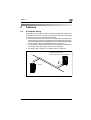
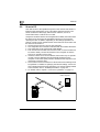

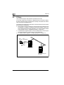


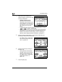


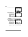


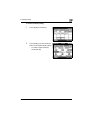


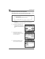


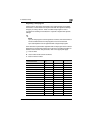

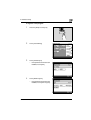


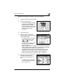


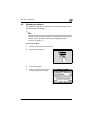


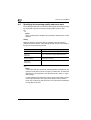

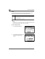


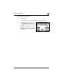
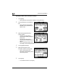

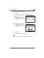


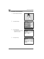
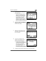


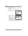
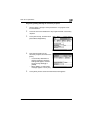


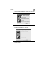


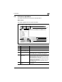
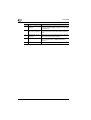
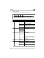


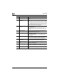
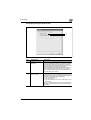

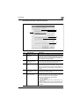


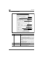

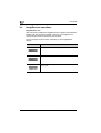

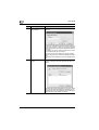
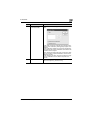


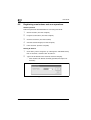
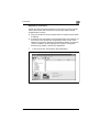
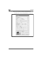
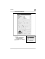
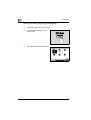

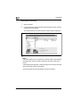


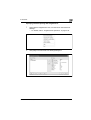


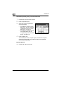


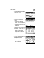


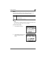

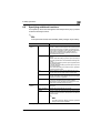

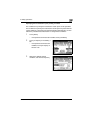
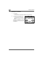


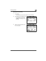


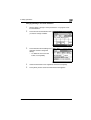


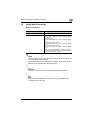

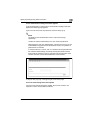
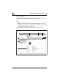

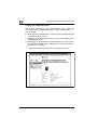


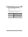

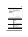


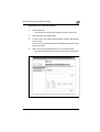
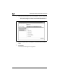


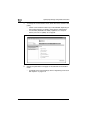


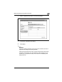


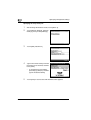


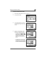


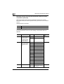


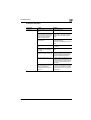


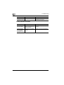


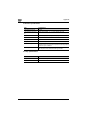
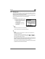


![User's Guide [Advanced Scan Operations]](http://vs1.manualzilla.com/store/data/006865872_1-8b3a85e3ed58d035968500e47824ff56-150x150.png)