1
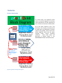
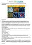
JameCo ‘imprint’
Manufacturer: JAMECO KITPRO
Manufacturer No.:
CJKIT-21420
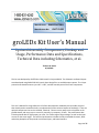
groLEDs Kit User’s Manual
Optional Assembly Components, Hookup and
Usage, Performance Data and Specifications,
Technical Data including Schematics, et al.
Thomas W. Gustin
8/29/2015
This kit was developed by GUSTECH as Club JameCo’s Project #21420. The Schematic and Board Layout
were developed using EAGLE PRO 6.3.0 tools; these design files are available upon request. The 2-layer
printed circuit board measures just 1.95” x 2.60”, and the assembly uses all thru-hole components.
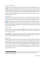
This User’s Manual for the groLEDs Kit is all of the documentation needed by the kit-builder, beyond
that already used to assemble the kit, to understand all of the technical aspects of the design. There are
optional components that can be installed, if desired. There are many ways to wire the power to the
groLEDs board, and many ways to control it; manually, by computer, or both. The performance data
includes plotted data for light output, per color, for a wide range of input voltages, as well as the input
current for the same ranges. The technical presentation includes the fully annotated schematic, black
and white photoplots of the printed circuit board layers, and board statistics.
Page 1 of 27
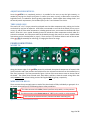
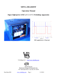
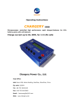
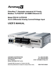
Figure 1: Six views of the dimly lit groLEDs Assemblies
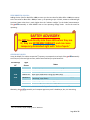
SAFETY ADVISORY
SAFTEY ADVISORY:
Do NOT Look directly into these LEDs when they are
lit; they are EXTREMELY BRIGHT, and can cause
temporary diminished sight with ‘lots of spots.’
Page 2 of 27
OPTIONAL ASSEMBLY: .................................... 10
CONTENTS
POWER SWITCHES: .................................... 10
POWER CONNECTOR:................................. 10
Table of Contents
GANG WIRING: .............................................. 11
SAFETY ADVISORY ........................................... 2
COMPUTER POWER SUPPLY: ...................... 11
CONTENTS ....................................................... 3
POWER SUPPLY NOTES: .......................... 12
TABLE OF FIGURES:.......................................... 4
HOW MANY groLEDs on a POWER SUPPLY:
.............................................................. 12
TABLE of TABLES .............................................. 4
OVERVIEW: ..................................................... 5
TITLE:........................................................... 5
BRIGHT: ....................................................... 5
ADJUSTABLE SPECTRUM: ............................. 5
DIRECTIONALLY FOCUSED: ........................... 5
EASILY CONTROLLED: ................................... 6
POWER-SAFE: .............................................. 6
INEXPENSIVE: .............................................. 6
RELIABLE: .................................................... 6
ADJUSTABLE BRIGHTNESS:........................... 7
THRU-HOLE ONLY: ....................................... 7
POWER CONNECTIONS: ................................... 7
WHERE TO: .................................................. 7
WIRE-SWITCH-RELAY ................................... 7
MANY POWER OPTIONS: ............................. 8
COMMON “+5v”: ..................................... 8
COMMON “GND”: ................................... 8
SEPARATE +V SOURCES: ........................... 8
COMMON CONTROL METHODS: .................. 9
ALWAYS ON ............................................. 9
REMOTELY CONTROLLED: ........................ 9
LOCAL & REMOTE CONTROLLED: ............. 9
LOCAL CONTROL only: ............................. 9
ALL LEDS at +5VDC: ................................ 13
ALL LEDS at +3.3VDC: ............................. 13
CHEAP more-POWER: ............................. 13
FIGURE 9 DETAILS: ..................................... 13
SWITCHES or RELAYS: ............................. 13
BOARD “A”: ............................................ 13
BOARD “B”: ............................................ 13
BOARD “C”: ............................................ 14
BOARDS “D”: .......................................... 14
BOARD “E”: ............................................ 14
TECHNICAL:.................................................... 15
BLOCK DIAGRAM:....................................... 15
SCHEMATIC: ............................................... 16
PC BOARD TOP COPPER:............................. 17
PC BOARD BOTTOM COPPER: ..................... 18
BOARD STATISTICS: .................................... 18
PERFORMANCE DATA: ................................... 19
POWER per VOLTAGE: ................................ 19
Red LEDs POWER: .................................. 19
White LEDs POWER: ............................... 20
Blue LEDs POWER: .................................. 21
AMBIENT SUNLIGHT: .................................. 22
LIGHT OUTPUT per VOLTAGE: .................... 22
Red LEDs LIGHT: ..................................... 22
Page 3 of 27
White LEDs LIGHT: ..................................23
Blue LEDs Light: ......................................24
VERY BRIGHT @ 3.31Vdc:........................25
OTHER LUX VALUES: ...............................25
HEAT: .........................................................26
VERTICAL HEAT RISE: ..............................26
HORIZONTAL HEAT RISE: .........................27
LIGHT AIRFLOW: .....................................27
Figure 15: White LEDs Total Power per Input
Voltage Plot ................................................... 20
Figure 16: Blue LEDs Total Power per Input
Voltage Plot ................................................... 21
Figure 17: Red LEDs Luminous (incident) Power
[Lux] per Input Voltages Plot .......................... 22
Figure 18: White LEDs Luminous (Incident)
Power [Lux] per Input Voltages Plot ............... 23
Figure 19: Blue LEDs Luminous (Incident) Power
[Lux] per Input Voltages Plot .......................... 24
the end ...................................................27
TABLE of TABLES
TABLE OF FIGURES:
Figure 1: Six views of the dimly lit groLEDs
Assemblies ...................................................... 2
Figure 2: Per LED Color Power Connection
Points .............................................................. 7
Figure 3: Switch Holes and the Electrical
Functions ........................................................ 7
Figure 4: Wiring LEDs to be ALWAYS ON .......... 9
Figure 5: Wiring LEDs for Remote (only) Control
........................................................................ 9
Figure 6: Wiring LEDs for Remote AND Local
Control ............................................................ 9
Figure 7: Power Slide Switches Optional
Installation .....................................................10
Figure 8: Optional Power Connector Installation
.......................................................................10
Figure 9: Multiple groLEDs Gang-Powered from
Computer Power Supply examples .................11
Figure 10: groLEDs Assembly Block Diagram ...15
Figure 11: groLEDs annotated Schematic ........16
Figure 12: groLEDs PC Board Top Copper Layer
.......................................................................17
Figure 13: groLEDs PC Board Bottom Copper
Layer ..............................................................18
Figure 14: Red LEDs Total Power per Input
Voltage Plot....................................................19
Table 1: ATX (computer) Power Supply
Connections ................................................... 12
Table 2: Red LEDs Power and Efficiency per
Input Voltages................................................ 19
Table 3: White LEDs Power and Efficiency per
Input Voltages................................................ 20
Table 4: Blue LEDs Power and Efficiency per
Input Voltages................................................ 21
Table 5: Red LEDs Lux levels at a few key Input
Voltages......................................................... 22
Table 6: White LEDs Lux Levels at a few key
Input Voltages................................................ 23
Table 7: Blue LEDs Lux Levels at a few key Input
Voltages......................................................... 24
Table 8: Some Common Light Sources Lux
Values ............................................................ 25
Table 9: Vertical groLEDs Assembly Heat
Measurements for various Input Voltages ...... 26
Table 10: Horizontal groLEDs Assembly Heat
Measurements for various Input Voltages ...... 27
Page 4 of 27
OVERVIEW:
TITLE:
groLEDs: Computer Controllable, Adjustable Broad Spectrum, High Brightness "grow 50-LEDs-lamp" kit
The groLEDs kit offers an economical, versatile, safe, efficient, and easy-to-use alternative to traditional
and commercial-grade Grow Lamp/Light products.
BRIGHT:
The three different colors of LEDs all include high luminosity intensity ratings1 measured in candela’s (cd)
instead of ‘normal’ LED millicandela (mcd) ratings. The Blue LEDs emit 57cd (57,000mcd), the White LEDs
emit 80cd (80,000mcd), and the Red LEDs emit 80cd (80,000mcd), when they are powered at their
specified nominal operating current levels. The equivalent light output is that of (very bright) 217
(standard) candles when all LEDs are lit. This document presents actual brightness measurement levels.
ADJUSTABLE SPECTRUM:
Unlike many full spectrum Grow Light Products, which attempt to provide some ‘additional’ red and
blue light energy mixed with the standard yellow/white, the groLEDs kit is designed to enable the user
to specifically select the light color output based upon growing needs. The color combinations include:
1)
2)
3)
4)
5)
6)
7)
8)
OFF (emulating night-time darkness)
BLUE Only ON, or
RED Only ON, or
WHITE Only ON, or
BLUE and RED Only ON, or
BLUE and WHITE Only ON, or
RED and WHITE Only ON, or
BLUE and RED and WHITE all ON.
This enables the user to emphasize the Blue end of the spectrum when attempting to promote healthy
vegetation growth, while the Red end is used when enhancing the budding and flowering phases of
growth, depending upon specific growth requirements.
DIRECTIONALLY FOCUSED:
Common Grow Lamps in the shape of (T5) Florescent Tubes or common incandescent shaped bulbs
broadcast their light in almost all directions, requiring mirror-reflectors to aim the light where it is
needed by the plants. LED Lamps with narrow beam widths ‘aim’ their light like spot lights right where it
is needed by the plants.
1
These brightness ratings are based upon the data sheet specifications for a nominal forward current of 20mA
each. Actual brightness levels for many different forward current levels are presented in the PERFORMANCE
section of this User’s Manual.
Page 5 of 27
EASILY CONTROLLED:
Most Grow Lamps, including many ‘hi-tech’ LED Lamp fixtures, only provide on-off capability. The
groLEDs kit is designed so that each bank of colors (Blue, White, and Red) can be individually controlled,
manually, or remotely via (computer-controlled) relay contacts, or both. This enables the user to control
the spectrum and the time that light is on versus off, changing as the growing cycles change on a perplant basis, if desired. Adjusting the input (low level DC) voltage also controls the brightness level. An
example of this might involve using +5.0Vdc for high-brightness growing conditions, while using +3.3Vdc
for (just) bright growing conditions2.
POWER-SAFE:
Mixing water and 115Vac never seemed like a good idea in any kind of growing environment. Nearly
every grow light available, including most LED Grow lamps, are powered by 115Vac, whether by a power
cord that plugs into a nearby socket, or one that screws into a lamp socket wired for 115Vac. The
groLEDs kit is designed to be run from +3.0Vdc to +5Vdc, enabling the user to safely use water near the
groLEDs kit fixture without fear of electrocution. The user places the 115Vac driven power supply in a
safe dry location remote from the growing (watering) area. Again, this "User’s Manual" lists the light
output values and the operating current levels for a broad range of operating voltages, from about
+3.0volts up to over +5.0volts.
INEXPENSIVE:
Compared to all other grow light solutions the groLEDs kit is very inexpensive. Not including the
printed circuit board and optional components, the JameCo catalog list-price for all 50 LEDs and their
current limiters is just $21.45.
Multiple groLEDs kits can be powered from a single, extremely inexpensive, ($15.00 common) Computer
(tower) power supply. Because these power supplies source high current levels for both +3.3volts and
+5.0volts, relay control of light levels and colors is very simple to implement.
RELIABLE:
LEDs have a life-cycle measured in tens-of-thousands-of hours, or many years; significantly longer than
any other grow-light solution. Many commercially available 115Vac powered LED Grow bulbs include
integrated AC-to-DC converters to create the proper power parameters for powering the LEDs within
the bulb-fixture. These converters, being active electronics subjected to relatively high-heat conditions
are prone to fail long before the actual light-emitting-diodes themselves. The groLEDs kit uses only
passive components, making it much more dependable for many years of service. Unlike most
Christmas LED strings, if and when a LED does fail on the groLEDs kit, all the other LEDs remain lit
without changing their intensities.
2
+3.3Vdc and +5.0Vdc are both high-current power sources on very inexpensive (tower) computer supplies, where
a switch or SPDT relay can select between these two voltage rails based upon growing needs. Examples are
provided later in this User’s Manual.
Page 6 of 27
ADJUSTABLE BRIGHTNESS:
Since the groLEDs kit is completely passive, it is possible for the user to vary the light intensity, as
needed, by varying the +5volts input (down to +3.0volts up to about +5.5volts), to decrease or increase the
brightness level, as needed for specific growing requirements. Details about these voltage levels, and
the overall power requirements, are included {later} in this "User’s Manual" for this kit.
THRU-HOLE ONLY:
The small 1.95” x 2.6” 2-layer printed circuit board uses thru-hole components only, making it a kit that
can be built by any level of expertise. All 50 LEDs are mounted on one side of the board ( see the pictures
on page 2), and all of the other components, including optional ones, are mounted on the backside of the
board. Since this is not a typical assembly process to include thru-hole components on both sides of a
printed circuit board, the instructions walk the kit-builder through the process to ensure reliable solder
connections and no scorched LEDs (or fingers). There are four 0.2” diameter holes in each of the corners
of the groLEDs kit assembly for mounting, or hanging the fixture for usage.
POWER CONNECTIONS:
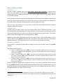
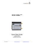
WHERE TO:
Figure 2: Per LED Color Power Connection Points
Along the bottom edge of the groLEDs printed circuit board the optional components of manual slide
(power) switches and a two-position terminal block for wire-to-board connections can be installed (on the
back side of the board). The view presented in figure 2 is that of this same area as seen on the top side of
the board. The (added) three colored ovals, Red, White, and Blue, show the actual wiring holes that
really connect to the current limiting resistors driving the LEDs, by group, respectively.
WIRE-SWITCH-RELAY:
There are several ways to apply power to each of the three banks of LEDs, individually or grouped. On a
per power connection point, the following depicts a few possibilities:
This hole connects to the LEDs; Power input from wire, switch, or relay contacts
This hole connects to the Power source via “+5v” by wire, switch, or relay contacts
This hole has no electrical function; used for the switch mounting only
Figure 3: Switch Holes and the Electrical Functions
Page 7 of 27
MANY POWER OPTIONS:
COMMON “+5v”:
The hole in Figure 2 labeled “+5v” is the main common power input connection. It may be wired
directly by a wire soldered into this particular hole, and may supply any safe and functional (positive)
voltage (referenced to the “GND” hole) that the kit-user wishes to apply to all three color-banks of LEDs for
this particular assembly.
As an alternative to directly soldering the input power wire to the board, the kit-builder may (optionally)
install the 2-position terminal block (on the back side of the board), as discussed later in this document.
This enables easier rewiring and reconfigurations, as growing conditions change.
This “+5v” hole also connects to all three center holes of all three triple-hole switch-installation
locations, as depicted in Figure 3.
COMMON “GND”:
The hole in Figure 2 labeled “GND” is the main common power return or GROUND connection. It may
be wired directly by a wire soldered into this particular hole, or the kit-builder may (optionally) install the
2-position terminal block (on the back side of the board), as discussed later in this document. This enables
easier rewiring and reconfigurations, as growing conditions change.
Regardless of the number and voltage levels of power sources used to drive the three different colorbanks of LEDs on a per groLEDs board basis, ALL of the power sources MUST have the same common
GROUND connection. This will be shown clearly in some of the wiring examples that follow.
SEPARATE +V SOURCES:
As mentioned, it is possible to supply different voltages, one each per color-bank of LEDs, per groLEDs
assembly.
One simple example might be:
Connect +4.22volts (referenced to “GND”), via a wire to the power hole (top hole with the blue oval
in figure 2) of the “BLU” switch hole patterns, to turn on the Blue LEDs (will need at least 600mA of
current driving capacity).
Connect +4.12volts (referenced to “GND”), via a wire to the power hole (right hole with the white
oval in figure 2) of the “WHT” switch hole patterns, to turn on the White LEDs (will need at least
200mA of current driving capacity).
Connect +3.99volts (referenced to “GND”), via a wire to the power hole (top hole with the red oval in
figure 2) of the “RED” switch hole patterns, to turn on the Red LEDs ( will need at least 200mA of
current driving capacity).
These three different voltage levels3 (regardless of how they are sourced or controlled) will drive all 50 LEDs
on the groLEDs assembly to their nominal 20mA operating current levels, providing ( theoretically) the
light levels depicted in the block diagram for this kit (see step 1 of the Assembly Instructions, and as listed in
the OVERVIEW-BRIGHT text on page 5 of this document).
3
These three data-sheet theoretical voltage levels of +4.22, +4.12 and +3.99 volts are different from the actual
measured values of +4.18, +4.18 and +3.96 volts, respectively, as presented in the PERFORMANCE DATA section on
pages 19 to 21.
Page 8 of 27
COMMON CONTROL METHODS:
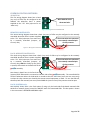
ALWAYS ON:
This first wiring diagram shows how a bank
(any color) of LEDs may be configured to be
ALWAYS ON whenever there is power
supplied to the “+5v” hole (referenced to the
“GND” hole).
Wire soldered across
these two holes
Figure 4: Wiring LEDs to be ALWAYS ON
REMOTELY CONTROLLED:
This second wiring diagram shows how a bank (any color) of LEDs may be configured to be remotely
controlled whenever there is power supplied
These two wires are connected
to the “+5v” hole (referenced to the “GND” hole)
to a remotely controlled pair
by a remotely controlled (computer, for
instance) relay.
of relay contacts
Figure 5: Wiring LEDs for Remote (only) Control
LOCAL & REMOTE CONTROLLED:
This third wiring diagram shows how a bank (any color) of LEDs may be configured to be remotely
controlled whenever there is power supplied
These two wires are connected
to the “+5v” hole (referenced to the “GND” hole)
to a remotely controlled pair
by a remotely controlled (computer, for
instance) relay, AND also locally by the (wiredof relay contacts
in-parallel) slide switch on the back side of the
groLEDs assembly.
Figure 6: Wiring LEDs for Remote AND Local Control
Not shown in detail here is the fact that the
(optional) SPDT Slide switch is mounted on the back side of the groLEDs assembly. The controlled LEDs
will be lit whenever either the slide switch is moved to short the two holes ( shown with wire connections)
or when the relay contacts are closed by the remote control equipment, or both. To turn the LEDs off,
therefore, both the manual (local control) switch AND the (remote control) relay contacts must be open.
LOCAL CONTROL only:
Not explicitly shown here is the final option of using only the back-side-of-the-board mounted slide
switches to manually (locally) control the ON/OFF state of its associated LEDs. This last option is shown
in the next section’s OPTIONAL ASSEMBLY topics.
Page 9 of 27
OPTIONAL ASSEMBLY:
POWER SWITCHES:
As mentioned several times, in both this document and that of the Assembly Instructions for this
groLEDs kit, there are four optional components (available from JameCo Electronics) that can be installed
on the assembly. The first three components are those of the (local control, alone, or in parallel with
remotely-controlled relay contacts) SPDT Slide Switches. The footprints on the printed circuit board for the
groLEDs kit are designed for JameCo Part#109171, SPDT Slide Switches.
If the kit-builder/user wishes to install these switches, do so from the bottom of the board, as shown in
Figure 7 below. If remotely controlled relay contacts are to be wired in, as well, as described on the
preceding page under the topic of “local & remote controlled”, then connect the relay wires to the top
side of the board, sharing the solder from the switch pins mounted from below.
All 3 switches are
Blue
shown in their OFF
LEDs
positions.
Manual
Power
Control
Switch
Figure 7: Power Slide Switches Optional Installation
POWER CONNECTOR:
If the kit-builder/user wishes to use a terminal block for wiring in a common power source ( to “+5v” and
“GND” holes), then use any 5mm-pitch
2-position terminal block, mounting it
on the bottom of the board. The
particular unit shown in Figure 8 is
JameCo Part#2094506.
Figure 8: Optional Power Connector Installation
Page 10 of 27
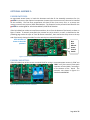
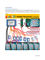
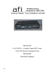
GANG WIRING:
COMPUTER POWER SUPPLY:
The following simplified wiring diagram depicts how multiple groLEDs assemblies can be run from a
single computer (tower) power supply, using switchable very-bright (at +5.0volts) and (just) bright (at
+3.3volts) fixed voltages that can be manually controlled or remotely (computer) controlled via relay
contacts.
ATX (computer)
Power Supply;
using +3.3v &
+5.0v DC
Outputs (only)
GND +3.3v +5.0v
SEE TEXT FOR
MORE DETAILS
groLEDs GANG-Powered examples
B
G
G
R
W
Wiring for a single
supply driving all
LEDs simultaneously
Wiring for a separate supplies
driving LEDs by color banks
(Red/White/Blue)
E
D
D
C
B
A
Figure 9: Multiple groLEDs Gang-Powered from Computer Power Supply examples
Page 11 of 27
POWER SUPPLY NOTES:
Supply
Voltage
Voltage
Range (minmax)
Wire
Color
+4.75
+5.25
+3.135
+3.465
Common (0
volts)
ORANGE
+12 Vdc
+11.40
+12.60
YELLOW
+5 V sb
+4.75
+5.25
PURPLE
Power ON
+5 Vsb or
GROUND
GREEN
+5 Vdc
+3.3 Vdc
GROUND
PWR_OK
-5 Vdc
-12 Vdc
GROUND or
+5 Vsb
-4.50 -5.50
-10.8 -13.2
RED
BLACK
Usage Notes:
These Red wires are used to power the groLEDs at (very
bright) 5volt levels
These Orange wires are used to power the groLEDs at (just
bright) 3.3volt levels
These Black wires are used to provide the ground path (power
return) for groLEDs assemblies
These Yellow wires, though not used by the groLEDs
assemblies, may be used for small 12volt fans if additional
ventilation or heat dissipation is desired
+5volts standby is present even when rest of the supply lines
are turned OFF (see “Power ON” below). NOT USED
[MUST] Connect this Green wire to a Black wire (always,
through a switch, or a computer-controlled pair of relay contacts) to
turn ON the power supply output voltages.
GREY
NOT USED
White
Blue
NOT USED
NOT USED
Table 1: ATX (computer) Power Supply Connections
As depicted in Figure 9 (on the preceding page), the Red Wires are +5volt lines, the Orange Wires are
+3.3volt lines, and the Black Wires are the Ground (power return) lines. Not shown in Figure 9 are:
1. The GREEN Wire needs to be connected to a BLACK wire to turn ON the power supply; and,
2. The YELLOW Wires (referenced to the Black wires) may power small 12-volt computer-type fans if
localized air movement is desired, for either cooling the groLEDs (see thermal measurements later
in this document) or for providing some ‘ventilation’ for the plants themselves.
HOW MANY groLEDs on a POWER SUPPLY:
Since there are many variations of switching power supplies designed to power varying capacities of
computers, it is difficult to say with certainty how many groLEDs can be powered from a single power
supply. The following examples may help understand how the sizing works.
In my own bench stock I have a pair of functional 250watt power supplies; with different current level
capacities for the two main voltage rails being used in the example: +5volts and +3.3volts.
1. Power supply #1 can supply +5V at 27amperes (=135Watts) and +3.3volts at 14amperes
(=46.2Watts). This is a total of 181.2Watts, with the remaining power (of 250Watts) for the
other voltage rails (see table 1 above).
2. Power supply #2 can supply +5V at 25amperes (=125Watts) and +3.3volts at 16amperes
(=52.8Watts). This is a total of 177.8Watts, with the remaining power (of 250Watts) for the
other voltage rails (see table 1 above).
Page 12 of 27
ALL LEDS at +5VDC:
If all 50 LEDs per groLEDs assembly are operated at +5volts, then 1.619Amperes of current is needed,
=8.095Watts. This means that 15 or 16 groLEDs assemblies can be (easily) powered from just one of
these two small 250Watt ATX (computer) power supplies using just the +5volts power rail.
ALL LEDS at +3.3VDC:
If all 50 LEDs per groLEDs assembly are operated at +3.3volts, then 0.424Amperes of current is needed,
=1.400Watts. This means that 33 or 37 groLEDs assemblies can be (easily) powered from just one of
these two small 250Watt ATX (computer) power supplies using just the +3.3volts power rail.
CHEAP more-POWER:
OK, let’s assume that you don’t have a spare computer power supply lying around. A 480Watt ATX
Power Supply (almost double the capacity of the ones noted above) can be had for just $14.994. This higher
wattage power supply can drive up to 66 groLEDs assemblies if they all run at +3.3volts or 22 groLEDs
assemblies if they all run at +5volts. This single power supply, therefore, could theoretically power up to
88 groLEDs assemblies before another power supply would be needed for more groLEDs assemblies.
FIGURE 9 DETAILS:
SWITCHES or RELAYS:
Figure 9 shows 8 examples of SPDT5 ‘contacts’ that can be either mechanical switches or
(computer-controlled) relay contacts, or a mix of both, as desired. Any of these ‘contacts’ with
three wire connections need to be SPDT, while any with just two wire connections can be
either SPDT (with one position unused) or SPST.
BOARD “A”:
Board “A”, in the bottom right corner of Figure 9, is the first groLEDs assembly whose wiring will be
briefly explored. It is configured to have all 50 of its LEDs running at +5volts when the switch or relay
contacts are closed (as shown). The ‘common’ connection on its SPDT ‘contacts’ connects a single wire to
the “+5V” input of the groLEDs assembly. The Power supply is bringing in +5volts (on a red wire) to this
set of SPDT ‘contacts. The groLEDs board itself will need to have three wire-jumpers installed for
“always on” as shown in Figure 4, slide switches installed for “local control” as shown in Figure 7, or
some other variation (see figures 5 and 6).
BOARD “B”:
Board “B” (next to Board “A” in Figure 9) is configured to have all 50 of its LEDs running at +3.3volts when
the switch or relay contacts are closed (as shown). The ‘common’ connection on its SPDT ‘contacts’
connects a single wire to the “+5V” input of the groLEDs assembly. The Power supply is bringing in
+3.3volts (on an orange wire) to this set of SPDT ‘contacts. As with Board “A”, Board “B” needs to be
configured for local, remote, or some combination of control of the supply to each of its color-banks of
LEDs since the whole board is receiving a common power voltage level (+3.3volts in this example).
4
Part# 83-15657, MCM Electronics (www.MCMelectronics.com) 1-800-543-4330; as found on page 132 of their
July 2015 (printed) catalog.
5
SPDT Single Pole Double Throw; whereas SPST Single Pole Single Throw
Page 13 of 27
BOARD “C”:
Board “C” is the last example of a (pair of) groLEDs boards where all 50 LEDs (per groLEDs board) are
running at the same voltage that is applied to their “+5V” input connection. In the top right corner of
Figure 9, just left of the picture of a groLEDs board, the bottom side of the board is shown with all four
optional components installed (three power slide switches and a 2-position terminal block). For all three
board examples discussed so far (“A”, “B”, and “C”) the black (GROUND) power supply wire connects to
the groLEDs board where the label “G” is depicted, while the input supply voltage is connected where
the label “” is shown.
Board “C” wiring is just slightly more complex than those of Board “A” and Board “B”. There is a pair of
SPDT contacts. The right one (of the pair) functions as an ON/OFF switch, just as in the two previous
examples. The left SPDT ‘contact’ selects between +5.0volts (on the red wire from the power supply) or
+3.3volts (on the orange wire from the power supply) to be applied to Board “C”.
BOARDS “D”:
There are two boards in Figure 9 labeled “D” because there are two groLEDs assemblies wired in
parallel; both functioning identically depending upon the three different SPDT ‘contact’ positions that
are supplying power to these groLEDs assemblies. Unlike the three previous examples, the two
groLEDs “D” assemblies are “always ON” when the power supply is turned on. What makes this
example so unique is the fact that all of the Red LEDs can be (just) bright running at +3.3volts or they can
be very bright running at +5volts; AND, all of the Blue LEDs can be (just) bright running at +3.3volts or
they can be very bright running at +5volts; AND, all of the White LEDs can be (just) bright running at
+3.3volts or they can be very bright running at +5volts.
The SPDT ‘contact’ common connections depicted in Figure 9 for this example (“D”) uses the wire
connections shown at the top of Figure 9 in the center. The switch or relay contacts that supply power
to all of the Red LEDs connects to the hole labeled “R” for both groLEDs boards. The switch or relay
contacts that supply power to all of the White LEDs connects to the hole labeled “W” for both groLEDs
boards. The switch or relay contacts that supply power to all of the Blue LEDs connects to the hole
labeled “B” for both groLEDs boards. Don’t forget to connect power supply GROUND (power return)
Black Wires to the holes labeled “G” for both groLEDs boards.
BOARD “E”:
There is just one board in Figure 9 labeled “E” (bottom left corner) that is configured for special growing
needs. Following the wires from the power supply down to the circuit connections for board “E” one
finds that the Red and Blue LEDs are always ON at a very-bright level (driven by +5volts-red wire), since
there are no intervening switches or relay contacts for controlling these connections. The White LEDs
on board “E” are controlled by the one switch or relay contacts that are powered by the +3.3volts
source from the power supply. So, board “E” lights up very-bright Red and Blue LEDs whenever the
power supply is on, and dimmer White LEDs are turned on and off as needed.
NOTE: The general terms of dim and just-bright and very-bright are only relative adjectives since, in
reality, all of these LEDs are too bright to look at (safely) even when they are powered at +3.0volts.
Absolute brightness levels are presented in the PERFORMANCE section of this document.
Page 14 of 27
TECHNICAL:
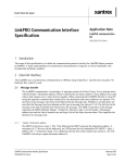
BLOCK DIAGRAM:
groLED s kit
Block Diagram
Power
Connect
Current
Limiters
+5Vdc
Input
Power
Connect
Current
Limiters
Power Connect
Options: Always
ON, Manual
ON/OFF Switch,
Relay Control,
et.al
Power
Connect
Current
Limiters
PC Board:
1.95” x 2.60”
30 different Blue
LEDs: 1900mcd
each; 468nm; ±15
Viewing angle
Bright Blue, clear lens
Narrow Beam ‘spot’
57,000mcd total
As noted earlier, the brightness levels
cited in this block diagram are the data
sheet specifications for LEDs operating at
their nominal current levels of 20mA each.
All of the topics covered so far in this
document are primarily concerned with
the application and distribution of power
inputs to the groLEDs, and less with their
actual brightness levels and the power
required under
various operating
conditions.
These latter topics are
discussed in greater detail in the
PERFORMANCE section of this document.
10 different White
LEDs: 8000mcd
each; (dominant)
650nm; ±120
Viewing angle
‘Broad’ White,
diffused lens,
Wide Beam ‘flood’
80,000mcd total
10 different Red
LEDs: 8000mcd
each; 635nm; ±20
Viewing angle
Bright Red, clear lens
Narrow Beam ‘spot’
80,000mcd total
Figure 10: groLEDs Assembly Block Diagram
Page 15 of 27
SCHEMATIC:
Figure 11: groLEDs annotated Schematic
Page 16 of 27
PC BOARD TOP COPPER:
Figure 12: groLEDs PC Board Top Copper Layer
Page 17 of 27
PC BOARD BOTTOM COPPER:
Figure 13: groLEDs PC Board Bottom Copper Layer
BOARD STATISTICS:
Board Size = 1.95” (49.53mm) ‘x’ by 2.60” (66.04mm) ‘y’.
This 2-layer board has 55 signals connecting 211 pads using 183 wires and 7 polygons. The top layer is
72.2% copper (see figure 12) while the bottom layer is only 60.5% copper (see figure 13 above). The
majority of the ‘wires=traces’ are 0.040” wide, with the minimum width being 0.032”. The isolation
regions on all (copper-pour) polygons is 0.016”. The four [pad] ‘drill’ sizes are 0.032” (0.8128mm), 0.051”
(1.3mm), and 0.063” (1.6mm) for copper-filled pads; and the largest drill size of 0.199” (5.08mm) are for
the four corner holes lacking copper for mounting the board in various ways. There are soldermask
layers for both top and bottom; but, there is only a top layer (minimal text) silkscreen.
Page 18 of 27
PERFORMANCE DATA:
POWER per VOLTAGE:
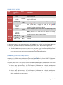
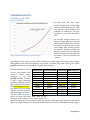
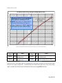
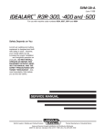
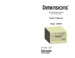
Red LEDs POWER:
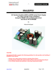
The Red LEDs, with their lower
forward voltage drop, include 100
series current limiting resistors. They
‘turn ON’ at a lower voltage at the
minimum of 1.69volts in this plot,
compared to the Blue and White
LEDs.
Figure 14: Red LEDs Total Power per Input Voltage Plot
As the input voltage increases, the
forward voltage drop across the Red
LEDs increases slightly, from 1.59volts
to 2.10volts, with the majority of the
total voltage drop occurring across
the resistors. Therefore, as the input
voltage increases, the total efficiency
drops because proportionally more of
the power is lost as heat across the
resistors.
The equation (for the trend line) can be used to determine the total power for any given input voltage.
When added to the trend line equations for the Blue and White LEDs, total power for the entire
groLEDs assembly can be predicted for any given input voltage(s).
The data tabulated (in Table 2) Voltage Input Total Current Input Total Power PWR Efficiency %
are just a few samples from
1.69Vdc
1mA
1.7mW
99.24%
extensive
bench
testing
2.99Vdc
109mA
325.9mW
63.69%
conducted on the first
3.31Vdc
137mA
453.5mW
60.13%
groLEDs assembly. Since this
3.52Vdc
156mA
549.1mW
56.94%
is NOT a large statistically
3.80Vdc
183mA
695.4mW
53.30%
significant population, use the
3.96Vdc
200mA
792mW
50.12%
data as approximations only.
4.31Vdc
232mA
999.9mW
47.91%
The Yellow Highlighted data is
4.51Vdc
252mA
1,136.5mW
45.58%
that where the input voltage
4.70Vdc
271mA
1,273.7mW
44.04%
causes the nominal 20mA per
5.01Vdc
303mA
1,518.0mW
41.63%
LED operating point to occur.
5.31Vdc
335mA
1,778.9mW
39.55%
The two BOLD BLUE Data
Table 2: Red LEDs Power and Efficiency per Input Voltages
points are those that occur when using an ATX
Computer Power Supply as the power source, as
discussed previously in this document. Note: the 5.31Vdc sampling was NOT included in the Plot of
Figure 14. A high end light test at +5.50Vdc needed 353mA of current for 1.9415Watts of Power usage.
Page 19 of 27
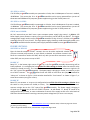
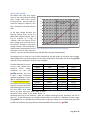
White LEDs POWER:
The White LEDs, with their higher
(than the Red LEDs) forward voltage
drop, include 56 series current
limiting resistors. They ‘turn ON’ at a
minimum voltage of 2.59volts in this
plot, compared to the Red and Blue
LEDs.
ALL WHITE LEDS: Total Power Input (y axis) per Voltage Input (x axis)
1,800.0
1,600.0
y = 198.17x2 - 794.13x + 719.56
R² = 0.9999
1,400.0
1,200.0
1,000.0
As the input voltage increases, the
forward voltage drop across the
White LEDs increases slightly, from a
low of 2.43volts to a high of
3.22volts, with the majority of the
total voltage drop occurring across
the resistors. Therefore, as the input
voltage increases, the total efficiency
drops because proportionally more of Figure 15: White LEDs Total Power per Input Voltage Plot
the power is lost as heat across the
resistors. They are still more efficient than the Red LEDs examples cited previously.
800.0
600.0
400.0
200.0
0.0
2.5
3.5
4.5
The equation (for the trend line) can be used to determine the total power for any given input voltage.
When added to the trend line equations for the Blue and Red LEDs, total power for the entire groLEDs
assembly can be predicted for any given input voltage(s).
The data tabulated (in Table 3) Voltage Input Total Current Input Total Power PWR Efficiency %
are just a few samples from
2.59Vdc
1mA
2.6mW
99.61%
extensive
bench
testing
2.99Vdc
38mA
113.6mW
93.02%
conducted on the first
3.31Vdc
78mA
258.2mW
87.13%
groLEDs assembly. Since this
3.51Vdc
106mA
372.1mW
83.69%
is NOT a large statistically
3.80Vdc
147mA
558.6mW
78.09%
significant population, use the
4.18Vdc
200mA
836mW
73.68%
data as approximations only.
4.31Vdc
228mA
982.7mW
71.73%
The Yellow Highlighted data is
4.51Vdc
260mA
1,172.6mW
69.56%
that where the input voltage
4.70Vdc
291mA
1,367.7mW
67.02%
causes the nominal 20mA per
5.00Vdc
340mA
1,700.0mW
63.8%
LED operating point to occur.
5.30Vdc
375mA
1,987.5mW
60.75%
The two BOLD BLUE Data
Table 3: White LEDs Power and Efficiency per Input Voltages
points are those that occur when using an ATX
Computer Power Supply as the power source, as
discussed previously in this document. Note: the 5.30Vdc sampling was NOT included in the Plot of
Figure 15. A high end light test at +5.50Vdc needed 419mA of current for 2.305Watts of Power usage.
The groLEDs user is reminded that the White LEDs are going to ‘flood’ the area with white light; they
are NOT narrow beam spot (light) LEDs like the Red and Blue LEDs used on the groLEDs.
Page 20 of 27
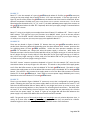
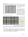
Blue LEDs POWER:
The Blue LEDs, with their higher
(similar to the White LEDs) forward
voltage drop, include 56 series
current limiting resistors. They ‘turn
ON’ at a minimum voltage of
2.52volts in this plot.
ALL BLUE LEDS: Total Power Input (y axis) per Voltage Input (x axis)
5,000.0
y = 608.2x2 - 2586.1x + 2603.6
R² = 0.9998
4,000.0
3,000.0
2,000.0
1,000.0
0.0
2.0
3.0
4.0
-1,000.0
Figure 16: Blue LEDs Total Power per Input Voltage Plot
5.0
As the input voltage increases, the
forward voltage drop across the Blue
LEDs increases slightly, from a low of
2.40volts to a high of 3.21volts, with
the majority of the total voltage drop
occurring across the resistors.
Therefore, as the input voltage
increases, the total efficiency drops
because proportionally more of the
power is lost as heat across the
resistors. They are still more efficient
than the Red LEDs examples cited previously.
The data tabulated (in Table 4)
are just a few samples from
extensive
bench
testing
conducted
on
the
first
3.31Vdc
209mA
691.8mW
86.83%
groLEDs assembly. Since this
3.50Vdc
285mA
997.5mW
84.11%
is NOT a large statistically
3.80Vdc
411mA
1,561.8mW
78.96%
significant population, use the
4.18Vdc
600mA
2,508.0mW
73.21%
data as approximations only.
4.31Vdc
642mA
2,767.0mW
71.63%
The Yellow Highlighted data is
4.51Vdc
735mA
3,314.9mW
69.11%
that where the input voltage
4.71Vdc
830mA
3,909.3mW
66.51%
causes the nominal 20mA per
5.01Vdc
976mA
4,889.8mW
63.40%
LED operating point to occur.
5.31Vdc
1,140mA
6,053.4mW
60.45%
The two BOLD BLUE Data
Table 4: Blue LEDs Power and Efficiency per Input Voltages
points are those that occur when using an ATX
Computer Power Supply as the power source, as
discussed previously in this document. Note: the 5.31Vdc sampling was NOT included in the Plot of
Figure 16. A high end light test at +5.51Vdc needed 1.213Amperes of current for 6.683Watts of Power
usage.
Voltage Input Total Current Input
2.52Vdc
1mA
2.98Vdc
88mA
Total Power
2.5mW
262.2mW
PWR Efficiency %
99.61%
94.24%
It is recommended that the groLEDs user does NOT operate the groLEDs above +5.0volts input without
also using some kind of air-movement scheme to cool down the board. Later, temperature data will be
provided showing how the board heats up (above ambient temperatures) in still air. With just a small
amount of air moving over the groLEDs assembly, the groLEDs assembly was operated at 5.3volts and
at 5.5volts inputs for an extended period of time with no thermal issues.
Page 21 of 27
AMBIENT SUNLIGHT:
On 20 August 2015, at 1355 hrs, with no clouds in the sky 6, several light measurements7 were made for
establishing a comparison light-level, where many plants around the house attempt to ‘grow’. NOTE:
there is no direct sunlight here in the woods; three tiers of canopy (the maximum at about 150feet)
maintain a mostly-shaded growing environment. The average ambient light level was:
1209 Lux 112.4 Fc
LIGHT OUTPUT per VOLTAGE:
Red LEDs LIGHT:
ALL RED LEDS: LUX (y axis) per Voltage Input (x axis)
1400
y = 369.65x - 595.32
R² = 0.9971
Measured with Tenma Light Meter
#72-9195 at a distance of 12.0".
NOTE: The meter is calibrated to a
standard incandescent lamp at
color temperature 2856 K (which is
NOT peak for these 635nm LEDs).
1200
1000
800
600
400
200
0
1.00
1.50
2.00
2.50
3.00
3.50
4.00
4.50
5.00
Figure 17: Red LEDs Luminous (incident) Power [Lux] per Input Voltages Plot
Input
Voltage
3.31Vdc
5.01Vdc
Lux
Notes
ATX Power
629 Supply Voltage
Level
ATX Power
1225 Supply Voltage
Level
Input
Voltage
Lux
4.00Vdc
904
5.50Vdc
Voltages higher than +4.94Vdc resulted in
1333 light BRIGHTER than the ambient shaded
sunlight conditions.
Notes
Near the nominal operating point of 20mA
per Led
Table 5: Red LEDs Lux levels at a few key Input Voltages
6
Rare occurrence in Ohio; bright, mid-summer, mid-day, peak-growing time light level measurement.
All light measurements were made using a Tenma model 72-9195 Light Meter that provides both FootCandles
(Fc) and Lux readouts (where they define 1 FootCandle = 10.76 Lux). Except for the Ambient Light Measurements,
the Light Meter was exactly 12inches (one foot) from the Light Meter’s sensor.
7
Page 22 of 27
White LEDs LIGHT:
ALL WHITE LEDS: LUX (y axis) per Voltage Input (x axis)
400
350
Measured with Tenma Light Meter
#72-9195 at a distance of 12.0".
NOTE: The meter is calibrated to a
standard incandescent lamp at
color temperature 2856 K (which is
NOT peak for these White LEDs).
300
250
y = 143.88x - 354.77
R² = 0.9911
200
150
100
50
0
2.00
2.50
3.00
3.50
4.00
4.50
5.00
Figure 18: White LEDs Luminous (Incident) Power [Lux] per Input Voltages Plot
Input
Voltage
Lux
3.31Vdc
120.8
5.00Vdc
347
Notes
ATX Power Supply
Voltage Level
ATX Power Supply
Voltage Level
Input
Voltage
Lux
4.11Vdc
247
5.50Vdc
393 Highest voltage used for testing
Notes
Near the nominal operating point
of 20mA per Led
Table 6: White LEDs Lux Levels at a few key Input Voltages
Note that none of the White LEDs Lux readings were very high (compared to the Red and Blue LEDs)
because of the angle of dispersion. The White LEDs are FLOOD (lamps) LEDs with a very wide viewing
angle; not SPOT (lamps) LEDs like the Red and Blue LEDs used on the groLEDs assembly.
Page 23 of 27
Blue LEDs Light:
ALL BLUE LEDS: LUX (y axis) per Voltage Input (x axis)
2000
1800
Measured with Tenma Light Meter
#72-9195 at a distance of 12.0".
NOTE: The meter is calibrated to a
standard incandescent lamp at
color temperature 2856 K (which is
NOT peak for these 468nm LEDs).
1600
1400
1200
y = 753.92x - 1881
R² = 0.996
1000
800
600
400
200
0
2.00
2.50
3.00
3.50
4.00
4.50
5.00
Figure 19: Blue LEDs Luminous (Incident) Power [Lux] per Input Voltages Plot
Input
Voltage
3.31Vdc
5.01Vdc
Lux
Notes
ATX Power
Supply Voltage
Level
ATX Power
1832 Supply Voltage
Level
598
Input
Voltage
Lux
4.18Vdc
1320
5.51Vdc
Voltages higher than +4.05Vdc resulted in
2150 light BRIGHTER than the ambient shaded
sunlight conditions.
Notes
Near the nominal operating point of 20mA
per Led
Table 7: Blue LEDs Lux Levels at a few key Input Voltages
Page 24 of 27
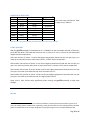
VERY BRIGHT @ 3.31Vdc:
Adding the Lux value for Red LEDs = 629 (see Table 5) to the Lux value for White LEDs = 120.8 (see Table 6)
to the Lux value for Blue LEDs = 598 (see Table 7), all operating at just 3.31Vdc, creates a combined light
Luminous Power value that is much higher than the “ambient sunlight” (in the shade) measurements.
The groLEDs assembly is VERY BRIGHT even at low operating voltage levels. Hence the need for
repeating…
SAFTEY ADVISORY:
Do NOT Look directly into these LEDs when they are
lit; they are EXTREMELY BRIGHT, and can cause
temporary diminished sight with ‘lots of spots.’
OTHER LUX VALUES:
It may be helpful, for relative comparison8 purposes, to compare the Lux levels of the groLEDs assembly
to a few (more) common light sources, where some familiarity may be beneficial:
Lux Level @
12”
Light
Source
283
450
810
1200
5Watts CFL
15Watts FL
60Watts
19Watts CFL
1590
80Watts FL
3810
6000
19720
100Watts
50Watts H
Vehicle
Notes
Not open spiral; enclosed in incandescent-style globe
Cool White 2-foot Florescent Tube Desk Lamp
‘standard’ (bare) Incandescent Light Bulb
Open spiral; 900Lumens rating @ 2700K (color)
Pair of 4feet 40Watts Cool White Florescent Tubes in a hanging
“workshop” open fixture
‘standard’ (bare) Incandescent Light Bulb
115Vac Halogen Spot Light (track lighting)
Truck’s headlamp (at a very close 12”) at unknown ratings
Table 8: Some Common Light Sources Lux Values
Obviously, the groLEDs assembly can’t compete against my truck’s headlamps; but, it is interesting.
8
Very un-scientific; simple samplings at 12” distances
Page 25 of 27
HEAT:
The groLEDs assembly, due to its totally passive design, converts some of the input power to heat
across the 50 current-limiting resistors (one per LED). As shown in previous discussions, the efficiency
drops as the input voltage goes up because the voltage drop across the (diodes) LEDs is not linear.
Therefore, the heat-losses increase as the input voltage goes up.
While the groLEDs assembly is much more efficient than incandescent bulbs, halogen lamps, and the
very high power grow lamp technologies of metal halide and high pressure sodium lamps, and even
some florescent bulb systems if you also consider the ballast power losses, they still generate some heat
that may become an issue in some growing environments.
Three simple thermal-rise experiments were conducted, summarized as:
1. Dead-air – no airflow with the groLEDs assembly vertical
2. Dead-air – no airflow with the groLEDs assembly horizontal
3. Light air flow (from a small desk fan 5 feet away) with the groLEDs assembly horizontal
For experiments #1 (see Table 9 below) and #2 (see Table 10 below) each voltage setting included a two
minute delay to permit the heat level to rise and stabilize, before the highest9 temperature reading was
acquired on the back (resistor) side using the Infrared Thermometer of an Extech Model EX210T. The
first tabulated value, at Vin= 0.00Vdc, is the baseline ‘ambient’ unpowered board temperature used for
the ‘rise’ values tabulated.
VERTICAL HEAT RISE:
Vin
Temperature Rise above Ambient Input Power10
0mW
0.00Vdc
Baseline
76.2F
182.19mW
2.58Vdc
77.3F
+1.1F
346.97mW
2.74Vdc
79.5F
+3.3F
763.49mW
3.00Vdc
82.2F
+6.0F
1.397Watts
3.30Vdc
89.9F
+13.7F
2.655Watts
3.75Vdc
107.7F
+31.5F
3.587Watts
4.02Vdc
122.1F
+45.9F
4.694Watts
4.30Vdc
138.0F
+61.8F
6.572Watts
4.71Vdc
161.6F
+85.4F
8.251Watts
5.03Vdc
183.5F
+107.3F
As mentioned in footnote 10, the
total power tabulated is equationderived, and very closely matches
samples acquired during testing.
All 50 LEDs were ‘on’, except for
when the “Vin” value was too low
for the Blue and White LEDs
(2.58Vdc in table 9). The ‘hottest’ spot
was consistently found on the top edge
of the (vertical) board, usually midway.
Table 9: Vertical groLEDs Assembly Heat Measurements for various Input Voltages
The ‘high’ heat values for the high
input voltage values were a bit of
a surprise until the total Power Input Values were added. 8.251Watts being dissipated by a single large
power resistor would be very warm to the touch. And, it must be stressed again that this was an
unrealistic, still-air experiment, where real growing environments would have some airflow to lower
these temperature values.
9
The Infrared (laser-pointer-guided) Thermometer was scanned over the whole back side of the groLEDs board
‘holding’ on the maximum reading found.
10
Total Power is calculated from the sum of the three different trend line equations presented in Figures 15, 16,
and 17 for the Red, White, and Blue LEDs, respectively, except for the lowest non-zero reading which only included
power for the Red LEDs, since the input voltage was not yet high enough to turn on the Blue and White LEDs.
Page 26 of 27
HORIZONTAL HEAT RISE:
Vin
Temperature Rise above Ambient Input Power11
0mW
0.00Vdc
Baseline
73.9F
173.50mW
2.55Vdc
74.8F
+0.9F
374.63mW
2.76Vdc
76.8F
+2.9F
763.49mW
3.00Vdc
81.5F
+7.6F
1.397Watts
3.30Vdc
88.3F
+14.4F
2.655Watts
3.75Vdc
112.6F
+38.7F
3.550Watts
4.01Vdc
124.5F
+50.6F
4.778Watts
4.32Vdc
138.2F
+64.3F
6.523Watts
4.70Vdc
161.9F
+88.0F
8.086Watts
5.00Vdc
185.5F
+111.6F
The same notes presented in Table
9 apply here in Table 10.
Table 10: Horizontal groLEDs Assembly Heat Measurements for various Input Voltages
LIGHT AIRFLOW:
With the groLEDs assembly still powered (at Vin = 5.00Vdc) from the last sample acquired in Table 10, a
small desk fan about 5 feet away was turned on low (I realize this is not very scientific) to see what would
happen with the temperatures.
After two minutes of ‘pause’ a scan-for-the-highest temperature found that the hot spot (right in the
middle of the board) was now at a much lower 155.6F, a 29.9F drop in temperature.
After another two minutes of ‘pause’ a scan-for-the-highest temperature found that the hot spot (still
right in the middle of the board) was now at an even lower 132.4F, another 23.2F drop in temperature.
After another two minutes of ‘pause’ another scan-for-the-highest temperature found that the hot spot
(still right in the middle of the board) was now at an even lower 131.7F.
After another two minutes of ‘pause’ a final scan-for-the-highest temperature found that the hot spot
(still right in the middle of the board) was now at a slightly lower 130.4F.
Some, even a little, airflow helps significantly when running the groLEDs assembly at high input
voltages.
the end
11
Total Power is calculated from the sum of the three different trend line equations presented in Figures 15, 16,
and 17 for the Red, White, and Blue LEDs, respectively, except for the lowest non-zero reading which only included
power for the Red LEDs, since the input voltage was not yet high enough to turn on the Blue and White LEDs.
Page 27 of 27