1
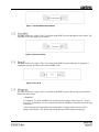
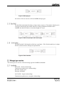
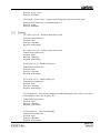
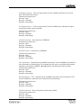
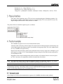
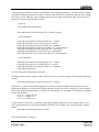
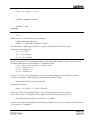
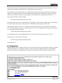
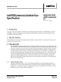
The scope of this specification is to define the communication protocol used by the LinkPRO battery monitor
(LinkPRO). A basic understanding of a-synchronous communication is required, as well as familiarity with
hexadecimal and binary numbers.
The LinkPRO uses a-synchronous communication at 2400 bps using 8 data bits, 1 stop bit and even parity. No
hardware flow control is used.
The LinkPRO communicates via messages. A message consists of at least 5 bytes. Every message starts
with the Header / Destination address which is followed by the Source address. These addresses are used
when a hub connects two or more devices together. When connecting the LinkPRO directly to a host PC
(using the optional communication interface kit), the destination and source addresses are ignored. The
next byte in the message is the Device ID followed by the Message type. Whether or not data bytes are
sent after the Message type byte depends on the type of message (see section 2.1.4). The last byte in the
message is the End of transfer byte which closes the message. The MSB of each byte in the message
represents the IDHT (IDentify Header / Trailer) bit. This bit is logic 1 for the Header / Destination
address byte and the End of transfer byte and logic 0 for all the bytes between them. This simplifies the
detection of a message start.
The IDHT of this byte is logic 1. The 7 bits following the IDHT represent the destination address. A
maximum of 127 devices can be addressed, not 128 because the bit combination FFh (IDHT = logic 1,
address 128 = 7 consecutive logic 1’s) is defined as the last byte of the transfer (see section 2.1.6). The
LinkPRO will always output destination address 0.
Figure 1: Header/Destination address
The IDHT of this byte is logic 0. The 7 bits following the IDHT represent the address of the sender. The
LinkPRO will always output source address 0.
Figure 2: Source Address
The IDHT of this byte is logic 0. The 7 bits following the IDHT represent what type of equipment is
sending the message. The Device ID of the LinkPRO is 22h.
Figure 3: Device ID
The IDHT of this byte is logic 0. The 7 bits following the IDHT represent the message type and can be
divided into three groups:
1. Handshake.
2. Commands. To put the LinkPRO in a certain state (for example ‘Alarm relays on’, ‘Alarm
relays off’, ‘Synchronize’ etc.) or to request data from the LinkPRO. No data bytes are following
a command.
3. Data. Messages that contain data (for example battery voltage, battery current or all the
settings of the monitor). The data will be sent in data bytes following the message type.
Figure 4: Message type
See section 2.2 for an overview of all the LinkPRO message types.
The data field contains data like battery voltage, battery current etc. The number of data bytes in
a message is theoretically not limited. However, because of hardware limitations of the
LinkPRO, the data field can have a maximum length of 27 bytes.
Figure 5: Data field (example with 3 data bytes)
The IDHT and the 7 following bits of this byte are all logic 1. This End of transfer byte is unique
because no other field in a message can represent FFh.
Figure 6: End of transfer
This section gives an overview of all the message types the LinkPRO understands.
0x00 ACK – Positive acknowledge.
Transmission repetition rate: on acknowledge
Direction: output / input
Data type: handshake
0x01 NACK – Negative acknowledge.
Transmission repetition rate: on negative acknowledge
Direction: output / input
Data type: handshake
0x02 NACK + repeat request – Negative acknowledge and request to send data again.
Transmission repetition rate: on communication error
Direction: output
Data type: handshake
0x12 Alarm switch off – Switches off the alarm switch.
Transmission repetition rate: Direction: input
Data type: command
Response: acknowledge
0x13 Alarm switch on – Switches on the alarm switch.
Transmission repetition rate: Direction: input
Data type: command
Response: acknowledge
0x20 Display test off – Disables display test.
Transmission repetition rate: Direction: input
Data type: command
Response: acknowledge
0x21 Display test on – Enables display test.
Transmission repetition rate: Direction: input
Data type: command
Response: acknowledge
0x22 Backlight off – Turns off the backlight (provided that backlight is not on due to a key-press
and backlight is not set up to be always on).
Transmission repetition rate: Direction: input
Data type: command
Response: acknowledge
0x23 Backlight on – Turns on the backlight.
Transmission repetition rate: Direction: input
Data type: command
Response: acknowledge
0x26 Request only off – Turns off request mode. Now the LinkPRO sends data every second
(this is the default factory status).
Transmission repetition rate: Direction: input
Data type: command
Response: acknowledge
0x27 Request only on – Turns on request mode. Now the LinkPRO only sends data on request
(requested by a data request command).
Transmission repetition rate: Direction: input
Data type: command
Response: acknowledge
0x28 Store functions – Store functions in EEPROM.
Transmission repetition rate: Direction: input
Data type: command
Response: acknowledge
0x29 Store history – Store history in EEPROM.
Transmission repetition rate: Direction: input
Data type: command
Response: acknowledge
0x2C Synchronize – Synchronizes the LinkPRO to the battery. See the LinkPRO user manual for
more information on synchronizing. This command does the same as synchronizing the monitor
manually by pressing the LinkPRO’s ◄ and ► buttons simultaneously for three seconds.
Transmission repetition rate: Direction: input
Data type: command
Response: acknowledge
0x2D Synchronize + CEF – Synchronizes the LinkPRO to the battery and recalculates the CEF.
See the LinkPRO user manual for more information on synchronizing.
Transmission repetition rate: Direction: input
Data type: command
Response: acknowledge
0x30 Reset functions – Reset all functions to their factory default.
Transmission repetition rate: Direction: input
Data type: command
Response: acknowledge
0x32 Reset Battery – Reset all battery history and status data and all internal battery registers.
The battery capacity setting (in function setup) will remain unchanged.
Transmission repetition rate: Direction: input
Data type: command
Response: acknowledge
0x33 Reset Alarms – Reset all currently active alarms. For an alarm to trigger again, its alarm off
condition must be met prior to its alarm on condition.
Transmission repetition rate: Direction: input
Data type: command
Response: acknowledge
0x3C Up switch pressed – User has pressed the ‘Up’ switch (labeled ►).
Transmission repetition rate: on up switch press
Direction: output
Data type: command
Response: n/a (output only)
0x3D Menu switch pressed – User has pressed the ‘Menu’ switch.
Transmission repetition rate: on menu switch press
Direction: output
Data type: command
Response: n/a (output only)
0x3E Down switch pressed – User has pressed the ‘Down’ switch (labeled ◄).
Transmission repetition rate: on down switch press
Direction: output
Data type: command
Response: n/a (output only)
0x40 Main Voltage request – Request for main battery voltage data. This message is built in only
for XBM compatibility and is not recommended. Use message type 0x60 instead.
Transmission repetition rate: Direction: input
Data type: command
Response: main battery voltage data (message 0x60)
0x41 Current request – Request for current data. This message is built in only for XBM
compatibility and is not recommended. Use message type 0x61 instead.
Transmission repetition rate: Direction: input
Data type: command
Response: current data (message 0x61)
0x42 Amphours request – Request for amphours data. This message is built in only for XBM
compatibility and is not recommended. Use message type 0x62 instead.
Transmission repetition rate: Direction: input
Data type: command
Response: amphours data (message 0x62)
0x44 State-of-Charge request – Request for state-of-charge data. This message is built in only
for XBM compatibility and is not recommended. Use message type 0x64 instead.
Transmission repetition rate: Direction: input
Data type: command
Response: state-of-charge data (message 0x64)
0x45 Time Remaining request – Request for time remaining data. This message is built in only
for XBM compatibility and is not recommended. Use message type 0x65 instead.
Transmission repetition rate: Direction: input
Data type: command
Response: time remaining data (message 0x65)
0x46 Temperature request – Request for temperature data. This message is built in only for
XBM compatibility and is not recommended. Use message type 0x66 instead.
Transmission repetition rate: Direction: input
Data type: command
Response: temperature data (message 0x66)
0x47 Monitor Status request – Request for monitor status bits. This message is built in only for
XBM compatibility and is not recommended. Use message type 0x67 instead.
Transmission repetition rate: Direction: input
Data type: command
Response: monitor status data (message 0x67)
0x4F All parameters request – Request for all measured and calculated parameters. This
message is built in only for XBM compatibility and is not recommended. Use message type
0x6F instead.
Transmission repetition rate: Direction: input
Data type: command
Response: main battery voltage data (message 0x60)
current data (message 0x61)
amphours data (message 0x62)
state-of-charge data (message 0x64)
time remaining data (message 0x65)
temperature data (message 0x66)
monitor status data (message 0x67)
auxiliary battery voltage data (message 0x68)
0x50 Parameter Select request – Request for selected parameter. This message is built in only
for XBM compatibility and is not recommended. Use message type 0x70 instead.
Transmission repetition rate: Direction: input
Data type: command
Response: parameter select (message 0x70)
0x51 Function Dump request – Request for function dump. This message is built in only for
XBM compatibility and is not recommended. Use message type 0x71 instead.
Transmission repetition rate: Direction: input
Data type: command
Response: function dump (message 0x71)
0x52 History Dump request – Request for history dump. This message is built in only for XBM
compatibility and is not recommended. Use message type 0x72 instead.
Transmission repetition rate: Direction: input
Data type: command
Response: history dump (message 0x72)
0x5F Firmware Version request – Request for firmware version. This message is built in only
for XBM compatibility and is not recommended. Use message type 0x7F instead.
Transmission repetition rate: Direction: input
Data type: command
Response: firmware version (message 0x7F)
0x60 Main Voltage request – Request for main battery voltage data.
Transmission repetition rate: Direction: input
Data type: command
Response: main battery voltage data (message 0x60)
0x61 Current request – Request for current data.
Transmission repetition rate: Direction: input
Data type: command
Response: current data (message 0x61)
0x62 Amphours request – Request for amphours data.
Transmission repetition rate: Direction: input
Data type: command
Response: amphours data (message 0x62)
0x64 State-of-Charge request – Request for state-of-charge data.
Transmission repetition rate: Direction: input
Data type: command
Response: state-of-charge data (message 0x64)
0x65 Time Remaining request – Request for time remaining data.
Transmission repetition rate: Direction: input
Data type: command
Response: time remaining data (message 0x65)
0x66 Temperature request – Request for temperature data.
Transmission repetition rate: Direction: input
Data type: command
Response: temperature data (message 0x66)
0x67 Monitor Status request – Request for monitor status bits.
Transmission repetition rate: Direction: input
Data type: command
Response: monitor status data (message 0x67)
0x68 Aux. Voltage request – Request for auxiliary battery voltage data.
Transmission repetition rate: Direction: input
Data type: command
Response: auxiliary battery voltage data (message 0x68)
0x6F All parameters request – Request for all measured and calculated parameters.
Transmission repetition rate: Direction: input
Data type: command
Response: main battery voltage data (message 0x60)
current data (message 0x61)
amphours data (message 0x62)
state-of-charge data (message 0x64)
time remaining data (message 0x65)
temperature data (message 0x66)
monitor status data (message 0x67)
auxiliary battery voltage data (message 0x68)
0x70 Parameter Select request – Request for selected parameter.
Transmission repetition rate: Direction: input
Data type: command
Response: parameter select (message 0x70)
0x71 Function Dump request – Request for function dump.
Transmission repetition rate: Direction: input
Data type: command
Response: function dump (message 0x71)
0x72 History Dump request – Request for history dump.
Transmission repetition rate: Direction: input
Data type: command
Response: history dump (message 0x72)
0x73 Status Dump request – Request for status dump.
Transmission repetition rate: Direction: input
Data type: command
Response: status dump (message 0x73)
0x74 External Alarms request – Request for external alarms.
Transmission repetition rate: Direction: input
Data type: command
Response: external alarms (message 0x74)
0x7F Firmware Version request – Request for firmware version.
Transmission repetition rate: Direction: input
Data type: command
Response: firmware version (message 0x7F)
0x60 Main Battery Voltage – Main battery voltage.
Transmission repetition rate: 1s / on request
Direction: output
Data Length: 3 bytes
Resolution: 0.01V / bit gain, 0V offset
Signed: no
Data range: 0.00 – 655.35V
Data type: measured
Databyte1<1..0>: Main Battery Voltage<15..14>
Databyte2<6..0>: Main Battery Voltage<13..7>
Databyte3<6..0>: Main Battery Voltage<6..0>
0x61 Current – Battery current.
Transmission repetition rate: 1s / on request
Direction: output
Data Length: 3 bytes
Resolution: 0.01A / bit gain, 0A offset
Signed: yes
Data range: -10485.75 – 10485.75A
Data type: measured
Databyte1<6>: Sign (0 = positive current, 1 = negative current)
Databyte1<5..0>: Current<19..14>
Databyte2<6..0>: Current<13..7>
Databyte3<6..0>: Current<6..0>
0x62 Amphours – Number of amphours removed from the battery.
Transmission repetition rate: 1s
Direction: output
Data Length: 3 bytes
Resolution: 0.1Ah / bit gain, 0Ah offset
Signed: yes
Data range: -9999.9 – 0.0Ah
Data type: calculated
Databyte1<6>: Sign (0 = positive amphours, 1 = negative amphours)
Databyte1<5..0>:Amphours<19..14>
Databyte2<6..0>:Amphours<13..7>
Databyte3<6..0>:Amphours<6..0>
0x64 State-of-Charge – State-of-charge of the battery in percent where 0% represents a fully
discharged, and 100% a fully charged battery.
Transmission repetition rate: 1s
Direction: output
Data Length: 3 bytes
Resolution: 0.1% / bit gain, 0% offset
Signed: no
Data range: 0.0 – 100.0%
Data type: calculated
Databyte1<1..0>: State-of-Charge <15..14>
Databyte2<6..0>: State-of-Charge <13..7>
Databyte3<6..0>: State-of-Charge <6..0>
0x65 Time Remaining – Time remaining until the battery needs to be charged.
Transmission repetition rate: 1s
Direction: output
Data Length: 3 bytes
Resolution: 1 minute / bit gain, 0 minutes offset
Signed: yes
Data range: 0 – 14400 minutes (= 240 hours)
Data type: calculated
Databyte1<6>: Sign (1 = negative time remaining)
Databyte1<5..0>: Time Remaining <19..14>
Databyte2<6..0>: Time Remaining <13..7>
Databyte3<6..0>: Time Remaining <6..0>
Note: A negative time remaining means the time remaining until the battery needs to be charged is infinite
because the average current is positive (battery is being charged). On the monitor this is displayed as four dashes:
---- h.
0x66 Temperature – Battery temperature.
Transmission repetition rate: 1s
Direction: output
Data Length: 3 bytes
Resolution: 0.1°C / bit gain, 0°C offset
Signed: yes
Data range: -20.0 – 50.0°C
Data type: measured
Databyte1<6>: Sign (0 = positive temperature, 1 = negative temperature)
Databyte1<1..0>: Temperature <15..14>
Databyte2<6..0>: Temperature <13..7>
Databyte3<6..0>: Temperature <6..0>
Note:
The step size of temperature is 0.5°C, so the outputted value changes with increments of 5.
0x67 Monitor Status – Status of the battery monitor.
Transmission repetition rate: 1s
Direction: output
Data Length: 3 bytes
Resolution: Signed: Data range: Data type: status
Databyte1<6>: reserved
Databyte1<5>: reserved
Databyte1<4>: Auto-Sync Voltage – Voltage > Auto-Sync Voltage level
Databyte1<3>: Auto-Sync Current – Current < Auto-Sync Current level
Databyte1<2>: Auto-Sync Charge – Battery has been discharge far enough to let it Auto-Sync
again
Databyte1<1>: XBM Compatibility Mode – Battery monitor is outputting data in XBM
compatibility mode
Databyte1<0>: Alarm Test – Alarm switch triggered due to command ‘Alarm switch on’
Databyte2<6>: Backlight Test – Backlight switched on due to command ‘Backlight on’
Databyte2<5>: Display Test – Display test switched on due to command ‘Display test on’
Databyte2<4>: No Temperature Sensor – No temperature sensor detected by battery monitor
Databyte2<3>: Aux. High Voltage Alarm – The auxiliary battery’s high voltage alarm is
triggered
Databyte2<2>: Aux. Low Voltage Alarm – The auxiliary battery’s low voltage alarm is
triggered
Databyte2<1>: Installer Lock – Installer-lock is enabled
Databyte2<0>: Main High Voltage Alarm – The main battery’s high voltage alarm is triggered
Databyte3<6>: Main Low Voltage Alarm – The main battery’s low voltage alarm is triggered
Databyte3<5>: Low Battery Alarm – The discharge floor is reached, main battery needs to be
charged
Databyte3<4>: Battery Flat – Main battery is fully discharged (0.0%)
Databyte3<3>: Battery Full – Main battery is fully charged (100.0%)
Databyte3<2>: Charge Battery – Main battery needs to be charged
Databyte3<1>: Monitor Out-of-Sync – Monitor is not in sync with battery, charge battery
Databyte3<0>: Monitor Reset – Monitor has been reset due to a power-loss
0x68 Aux. Battery Voltage – Auxiliary battery voltage.
Transmission repetition rate: 1s / on request
Direction: output
Data Length: 3 bytes
Resolution: 0.01V / bit gain, 0V offset
Signed: no
Data range: 0.00 – 655.35V
Data type: measured
Databyte1<1..0>: Aux. Battery Voltage<15..14>
Databyte2<6..0>: Aux. Battery Voltage<13..7>
Databyte3<6..0>: Aux. Battery Voltage<6..0>
0x70 Parameter Select – The parameter displayed on the battery monitor.
Transmission repetition rate: on request
Direction: output / input
Data Length: 2 bytes
Resolution: Signed: no
Data range: 0 – 6
Data type: status
Databyte1<0>: Parameter Select<7>
Databyte2<6..0>: Parameter Select<6..0>
0x71 Function Dump – Dump of all the settings of the battery monitor.
Transmission repetition rate: on request / on change
Direction: output / input
Data Length: see format specification in section 2.2.4
Resolution: see format specification in section 2.2.4
Signed: see format specification in section 2.2.4
Data range: see format specification in section 2.2.4
Data type: status
0x72 History Dump – Dump of all the history events.
Transmission repetition rate: on request / on change
Direction: output
Data Length: see format specification in section 2.2.5
Resolution: see format specification in section 2.2.5
Signed: see format specification in section 2.2.5
Data range: see format specification in section 2.2.5
Data type: status
0x73 Status Dump – Dump of all the status items.
Transmission repetition rate: on request / on change
Direction: output
Data Length: see format specification in section 2.2.6
Resolution: see format specification in section 2.2.6
Signed: see format specification in section 2.2.6
Data range: see format specification in section 2.2.6
Data type: status
0x74 External Alarms – External alarms to be triggered by the LinkPRO.
Transmission repetition rate: on request / on change
Direction: output
Data Length: 2 bytes
Resolution: Signed: Data range: Data type: status
Databyte1<0>: External Alarm 8
Databyte2<6>: External Alarm 7
Databyte2<5>: External Alarm 6
Databyte2<4>: External Alarm 5
Databyte2<3>: External Alarm 4
Databyte2<2>: External Alarm 3
Databyte2<1>: External Alarm 2
Databyte2<0>: External Alarm 1
0x7F Firmware Version – Firmware version of the battery monitor.
Transmission repetition rate: on request
Direction: output / input
Data Length: 2 bytes
Resolution: 0.01 / bit gain, 0 offset
Signed: no
Data range: 1.00 – 163.84
Data type: status
Databyte1<6..0>: FirmwareVersion<13..7>
Databyte2<6..0>: FirmwareVersion<6..0>
A function dump consists of 6 separate messages each with message type 0x71. Each message
contains a different function group indicated by the first data byte of the message. The function
groups are:
1. System properties
2. Low battery alarm settings
3. Low voltage alarm settings
4. High voltage alarm settings
5. Main battery properties
6. Battery monitor properties
The data bytes following the function group indicator contain the functions (LinkPRO settings)
of that group. This data needs some additional processing to actually represent the LinkPRO
settings. Some functions need an offset while others must be multiplied by a constant or variable
factor.
Message 1 out of 6 where Databyte1<6..0> equals 1.
F1.0 Auto-Sync Voltage – Auto-Sync Voltage (V).
Direction: output / input
Data Length: 1 byte
Resolution: 0.1V / bit gain, 8.0V offset
Signed: no
Data range: 8.0 – 33.0V
Data type: status
Databyte2<6..0>: Auto-Sync Voltage <13..7>
Databyte3<6..0>: Auto-Sync Voltage <6..0>
Auto-Sync Voltage = ((((Databyte2 * 0x80) + Databyte3) * 0.1) + 8.0) * F6.5
F1.1 Auto-Sync Current – Auto-Sync Current (% of battery capacity).
Direction: output / input
Data Length: 1 byte
Resolution: 0.1% / bit gain, 0.5% offset
Signed: no
Data range: 0.5 – 10.0%
Data type: status
Databyte4<6..0>: Auto-Sync Current <6..0>
Auto-Sync Current = (Databyte4 * 0.1) + 0.5
F1.2 Auto-Sync Time – Auto-Sync time (seconds).
Direction: output / input
Data Length: 1 byte
Resolution: see table 1, 1 item offset
Signed: no
Data range: 1 – 12
Data type: status
Databyte5<6..0>: Auto-Sync Time <6..0>
Auto-Sync Time = table_read(Databyte5 + 1)
F1.3 Discharge Floor – Discharge floor (%).
Direction: output / input
Data Length: 1 byte
Resolution: 1% / bit gain, 0% offset
Signed: no
Data range: 0 – 99%
Data type: status
Databyte6<6..0>: Discharge Floor <6..0>
Discharge Floor = Databyte6
F1.4 Battery Temperature – Battery temperature (°C).
Direction: output / input
Data Length: 1 byte
Resolution: 1°C / bit gain, -20°C offset
Signed: no
Data range: -20 – 50°C / AU
Data type: status
Databyte7<6..0>: Battery Temperature <6..0>
if Databyte7 = 51
then Battery Temperature = ‘AU’
else Battery Temperature = Databyte7 - 20
F1.5 Time Remaining Averaging Period – Time remaining averaging period.
Direction: output / input
Data Length: 1 byte
Resolution: Signed: no
Data range: 0 – 2
Data type: status
Databyte8<6..0>: Time Remaining averaging period <6..0>
Time Remaining averaging period = Databyte8
Message 2 out of 6 where Databyte1<6..0> equals 2.
F2.0 Low battery alarm on SOC – Low battery alarm on (%).
Direction: output / input
Data Length: 1 byte
Resolution: 1% / bit gain, 0% offset
Signed: no
Data range: 0 – 99%
Data type: status
Databyte2<6..0>: Low battery alarm on SOC <6..0>
Low battery alarm on SOC = Databyte2
F2.1 Low battery alarm on Volt – Low battery alarm on (V).
Direction: output / input
Data Length: 1 byte
Resolution: 0.1V / bit gain, 8.0V offset
Signed: no
Data range: 8.0 – 33.0V
Data type: status
Databyte3<6..0>: Low battery alarm on Volt <13..7>
Databyte4<6..0>: Low battery alarm on Volt <6..0>
Low battery alarm on Volt = ((((Databyte3 * 0x80) + Databyte4) * 0.1) + 8.0) * F6.5
F2.2 Low battery alarm off SOC – Low battery alarm off (%).
Direction: output / input
Data Length: 1 byte
Resolution: 1% / bit gain, 1% offset
Signed: no
Data range: 1 – 100% / FULL
Data type: status
Databyte5<6..0>: Low battery alarm off SOC <6..0>
if Databyte5 = 100
then Low battery alarm off SOC = ‘FULL’
else Low battery alarm off SOC = Databyte5 + 1
F2.3 Low battery alarm on delay – Low battery alarm on delay (seconds).
Direction: output / input
Data Length: 1 byte
Resolution: see table 1
Signed: no
Data range: 0 – 11
Data type: status
Databyte6<6..0>: Low battery alarm on delay <6..0>
Low battery alarm on delay = table_read(Databyte6)
F2.4 Minimum alarm on time – Minimum ‘alarm on’ time (hh:mm).
Direction: output / input
Data Length: 1 byte
Resolution: see table 2
Signed: no
Data range: 0 – 19
Data type: status
Databyte7<6..0>: Minimum alarm on time <6..0>
Minimum alarm on time = table_read(Databyte7)
F2.5 Maximum alarm on time – Maximum ‘alarm on’ time (hh:mm).
Direction: output / input
Data Length: 1 byte
Resolution: see table 2, 1 item offset
Signed: no
Data range: 1 – 20
Data type: status
Databyte8<6..0>: Maximum alarm on time <6..0>
Maximum alarm on time = table_read(Databyte8 + 1)
F2.6 Enable low battery alarm – Enable low battery alarm / use contact.
Direction: output / input
Data Length: 1 byte
Resolution: see table 3
Signed: no
Data range: 0 – 9
Data type: status
Databyte9<6..0>: Enable low battery alarm <6..0>
Enable low battery alarm = table_read(Databyte9)
Message 3 out of 6 where Databyte1<6..0> equals 3.
F3.0 Main low voltage alarm on – Main battery low voltage alarm on (V).
Direction: output / input
Data Length: 1 byte
Resolution: 0.1V / bit gain, 8.0V offset
Signed: no
Data range: 8.0 – 33.0V
Data type: status
Databyte2<6..0>: Main low voltage alarm on <13..7>
Databyte3<6..0>: Main low voltage alarm on <6..0>
Main low voltage alarm on = ((((Databyte2 * 0x80) + Databyte3) * 0.1) + 8.0) * F6.5
F3.1 Main low voltage alarm on delay – Main battery low voltage alarm on delay (seconds).
Direction: output / input
Data Length: 1 byte
Resolution: see table 1
Signed: no
Data range: 0 – 11
Data type: status
Databyte4<6..0>: Main low voltage alarm on delay <6..0>
Main low voltage alarm on delay = table_read(Databyte4)
F3.2 Enable main low voltage alarm – Enable main battery low voltage alarm / use contact.
Direction: output / input
Data Length: 1 byte
Resolution: see table 3
Signed: no
Data range: 0 – 9
Data type: status
Databyte5<6..0>: Enable main low voltage alarm <6..0>
Enable main low voltage alarm = table_read(Databyte5)
F3.3 Aux. low voltage alarm on – Auxiliary battery low voltage alarm on (V).
Direction: output / input
Data Length: 1 byte
Resolution: 0.1V / bit gain, 8.0V offset
Signed: no
Data range: 8.0 – 33.0V
Data type: status
Databyte6<6..0>: Aux. low voltage alarm on <13..7>
Databyte7<6..0>: Aux. low voltage alarm on <6..0>
Aux. low voltage alarm on = ((((Databyte2 * 0x80) + Databyte3) * 0.1) + 8.0) * F6.5
F3.4 Aux. low voltage alarm on delay – Auxiliary battery low voltage alarm on delay (seconds).
Direction: output / input
Data Length: 1 byte
Resolution: see table 1
Signed: no
Data range: 0 – 11
Data type: status
Databyte8<6..0>: Aux. low voltage alarm on delay <6..0>
Aux. low voltage alarm on delay = table_read(Databyte8)
F3.5 Enable aux. low voltage alarm – Enable auxiliary battery low voltage alarm / use contact.
Direction: output / input
Data Length: 1 byte
Resolution: see table 3
Signed: no
Data range: 0 – 9
Data type: status
Databyte9<6..0>: Enable aux. low voltage alarm <6..0>
Enable aux. low voltage alarm = table_read(Databyte9)
Message 4 out of 6 where Databyte1<6..0> equals 4.
F4.0 Main high voltage alarm on – Main battery high voltage alarm on (V).
Direction: output / input
Data Length: 1 byte
Resolution: 0.1V / bit gain, 10.0V offset
Signed: no
Data range: 10.0 – 35.0V
Data type: status
Databyte2<6..0>: Main high voltage alarm on <13..7>
Databyte3<6..0>: Main high voltage alarm on <6..0>
Main high voltage alarm on = ((((Databyte2 * 0x80) + Databyte3) * 0.1) + 10.0) * F6.5
F4.1 Main high voltage alarm on delay – Main battery high voltage alarm on delay (seconds).
Direction: output / input
Data Length: 1 byte
Resolution: see table 1
Signed: no
Data range: 0 – 11
Data type: status
Databyte4<6..0>: Main high voltage alarm on delay <6..0>
Main high voltage alarm on delay = table_read(Databyte4)
F4.2 Enable main high voltage alarm – Enable main battery high voltage alarm / use contact.
Direction: output / input
Data Length: 1 byte
Resolution: see table 3
Signed: no
Data range: 0 – 9
Data type: status
Databyte5<6..0>: Enable main high voltage alarm <6..0>
Enable main high voltage alarm = table_read(Databyte5)
F4.3 Aux. high voltage alarm on – Auxiliary battery high voltage alarm on (V).
Direction: output / input
Data Length: 1 byte
Resolution: 0.1V / bit gain, 8.0V offset
Signed: no
Data range: 10.0 – 35.0V
Data type: status
Databyte6<6..0>: Aux. high voltage alarm on <13..7>
Databyte7<6..0>: Aux. high voltage alarm on <6..0>
Aux. high voltage alarm on = ((((Databyte2 * 0x80) + Databyte3) * 0.1) + 10.0) * F6.5
F4.4 Aux. high voltage alarm on delay – Auxiliary battery high voltage alarm on delay
(seconds).
Direction: output / input
Data Length: 1 byte
Resolution: see table 1
Signed: no
Data range: 0 – 11
Data type: status
Databyte8<6..0>: Aux. high voltage alarm on delay <6..0>
Aux. high voltage alarm on delay = table_read(Databyte8)
F4.5 Enable aux. high voltage alarm – Enable auxiliary battery high voltage alarm / use contact.
Direction: output / input
Data Length: 1 byte
Resolution: see table 3
Signed: no
Data range: 0 – 9
Data type: status
Databyte9<6..0>: Enable aux. high voltage alarm <6..0>
Enable aux. high voltage alarm = table_read(Databyte9)
Message 5 out of 6 where Databyte1<6..0> equals 5.
Reserved – Don’t use
Databyte2<6..0>: Reserved
F5.0 Battery capacity – Battery capacity (Ah).
Direction: output / input
Data Length: 2 bytes
Resolution: variable, 20Ah offset
Signed: no
Data range: 20 – 9990Ah
Data type: status
Databyte3<6..0>: Battery capacity <13..7>
Databyte4<6..0>: Battery capacity <6..0>
Temporary Value = ((Databyte3 * 0x80) + Databyte4)
if Temporary Value < 980
then Battery capacity = Temporary Value + 20
else if Temporary Value < 1780
then Battery capacity = ((Temporary Value – 980) * 5) + 1000
else Battery capacity = ((Temporary Value – 1780) * 10) + 5000
F5.1 Nominal discharge rate – Nominal discharge rate (hours).
Direction: output / input
Data Length: 1 byte
Resolution: 1h / bit gain, 1h offset
Signed: no
Data range: 1 – 20h
Data type: status
Databyte5<6..0>: Nominal discharge rate <6..0>
Nominal discharge rate = Databyte5 + 1
F5.2 Nominal temperature – Nominal temperature (°C).
Direction: output / input
Data Length: 1 byte
Resolution: 1°C / bit gain, 0°C offset
Signed: no
Data range: 0 – 40h
Data type: status
Databyte6<6..0>: Nominal temperature <6..0>
Nominal temperature = Databyte6
F5.3 Temperature Coefficient – Battery temperature coefficient (%cap/°C).
Direction: output / input
Data Length: 1 byte
Resolution: 0.01%cap/°C / bit gain, 0.00%cap/°C offset
Signed: no
Data range: OFF / 0.01 – 1.00%cap/°C
Data type: status
Databyte7<6..0>: Temperature Coefficient <6..0>
if Databyte7 = 0
then Temperature Coefficient = ‘OFF’
else Temperature Coefficient = Databyte7 * 0.01
F5.4 Peukert Exponent – Peukert exponent.
Direction: output / input
Data Length: 1 byte
Resolution: 0.01 / bit gain, 1.00 offset
Signed: no
Data range: 1.00 – 1.50
Data type: status
Databyte8<6..0>: Peukert Exponent <6..0>
Peukert Exponent = (Databyte8 * 0.01) + 1.00
F5.5 Self discharge rate – Self discharge rate (%/month).
Direction: output / input
Data Length: 1 byte
Resolution: 0.1%/month / bit gain, 0.0%/month offset
Signed: no
Data range: OFF / 0.1 – 25.0%/month
Data type: status
Databyte9<6..0>: Self discharge rate <6..0>
if Databyte9 = 0
then Self discharge rate = ‘OFF’
else Self discharge rate = Databyte9 * 0.1
F5.6 Charge Efficiency – Charge efficiency factor / CEF (%).
Direction: output / input
Data Length: 1 byte
Resolution: 1% / bit gain, 50% offset
Signed: no
Data range: 50 – 100% / AU
Data type: status
Databyte10<6..0>: Charge Efficiency <6..0>
If Databyte10 = 51
then Charge Efficiency = ‘AU’
else Charge Efficiency = Databyte10 + 50
Message 6 out of 6 where Databyte1<6..0> equals 6.
F6.0 Display Parameter – Display parameter.
This is a special (sort of hidden) function. On the LinkPRO itself, reading out F6.0 will give you
the battery monitor’s firmware version. Since the firmware version can be retrieved thru its own
message via the LinkPRO communication kit software, the necessity of retrieving it via the
function dump becomes obsolete. Therefore F6.0 is used to enable / disable the readout of each
individual parameter in normal operation of the LinkPRO. When a parameter readout is enabled,
its corresponding bit in Databyte2 is set otherwise it is cleared. Note that this function only
affects the readout on the LinkPRO itself, a disabled parameter can always be retrieved via the
LinkPRO communication kit software.
Direction: output / input
Data Length: 1 byte
Resolution: Signed: no
Data range: Data type: status
Databyte2<0>: Enable / disable main battery Voltage readout
Databyte2<1>: Enable / disable auxiliary battery Voltage readout
Databyte2<2>: Enable / disable Current readout
Databyte2<3>: Enable / disable Amphours readout
Databyte2<4>: Enable / disable State-of-Charge readout
Databyte2<5>: Enable / disable Time Remaining readout
Databyte2<6>: Enable / disable Temperature readout
Display Parameter = Databyte2
F6.1 Shunt amp. rating – Shunt ampere rating (A).
Direction: output / input
Data Length: 1 byte
Resolution: see table 4
Signed: no
Data range: 10 – 9000A
Data type: status
Databyte3<6..0>: Shunt amp. rating <6..0>
Shunt amp. Rating = table_read(Databyte3)
F6.2 Shunt mV rating – Shunt mV rating (mV).
Direction: output / input
Data Length: 1 byte
Resolution: 10mV / bit gain, 50mV offset
Signed: no
Data range: 50 / 60mV
Data type: status
Databyte4<6..0>: Shunt mV rating <6..0>
Shunt mV Rating = (Databyte4 * 10) + 50
F6.3 Backlight Mode – Display backlight mode.
Direction: output / input
Data Length: 1 byte
Resolution: see table 1
Signed: no
Data range: OFF / 5 – 300 / ON / AU
Data type: status
Databyte5<6..0>: Backlight mode <6..0>
if Databyte5 = 0
then Backlight mode = ‘OFF’
else if Databyte5 = 13
then Backlight mode = ‘ON’
else if Databyte5 = 14
then Backlight mode = ‘AU’
else Backlight mode = table_read(Databyte5)
F6.4 Alarm Contact Polarity – Alarm contact polarity.
Direction: output / input
Data Length: 1 byte
Resolution: Signed: no
Data range: NO / NC
Data type: status
Databyte6<6..0>: Alarm Contact Polarity <6..0>
if Databyte6 = 0
then Alarm Contact Polarity = ‘NO’
else Alarm Contact Polarity = ‘NC’
F6.5 Voltage Prescaler – Voltage prescaler.
Direction: output / input
Data Length: 1 byte
Resolution: Signed: no
Data range: 1 / 5 / 10
Data type: status
Databyte7<6..0>: Voltage Prescaler <6..0>
if DataByte7 = 0
then Voltage Prescaler = 1
else if DataByte7 = 1
then Voltage Prescaler = 5
else Voltage Prescaler = 10
F6.6 Temperature Unit Selection – Temperature unit selection.
Direction: output / input
Data Length: 1 byte
Resolution: Signed: no
Data range: °C / °F
Data type: status
Databyte8<6..0>: Temperature Unit Selection <6..0>
if Databyte8 = 0
then Temperature Unit Selection = ‘°C’
else Temperature Unit Selection = ‘°F’
F6.7 Auxiliary input mode – Auxiliary input mode.
Direction: output / input
Data Length: 1 byte
Resolution: Signed: no
Data range: 0 – 1
Data type: status
Databyte9<6..0>: Auxiliary input mode <6..0>
Auxiliary input mode = Databyte9
F6.8 Communication mode – Communication mode.
Direction: output / input
Data Length: 1 byte
Resolution: Signed: no
Data range: 0 – 3
Data type: status
Databyte10<6..0>: Communication mode <6..0>
Communication mode = Databyte10
F6.9 Setup Lock – Setup lock.
Direction: output / input
Data Length: 1 byte
Resolution: Signed: no
Data range: OFF / ON
Data type: status
Databyte11<6..0>: Setup Lock <6..0>
if Databyte11 = 0
then Setup Lock = ‘OFF’
else Setup Lock = ‘ON’
A history dump consists of 2 separate messages each with message type 0x72. Each message
contains a different history group indicated by the first data byte of the message. The history
groups are:
1. Battery history
2. Alarm history
The data bytes following the history group indicator contain the history items of that group. This
data may need some additional processing to actually represent the LinkPRO history value.
Message 1 out of 2 where Databyte1<6..0> equals 1.
H1.0 Average Discharge (Ah) – Average discharge in Amphours (Ah).
Direction: output
Data Length: 3 bytes
Resolution: 0.1Ah / bit gain, 0.0Ah offset
Signed: no (always negative)
Data range: -9999.9 – 0Ah
Data type: calculated
Databyte2<1..0>: Average Discharge (Ah) <15..14>
Databyte3<6..0>: Average Discharge (Ah) <13..7>
Databyte4<6..0>: Average Discharge (Ah) <6..0>
H1.1 Average Discharge (%) – Average discharge in percent state-of-charge (%).
Direction: output
Data Length: 2 bytes
Resolution: 0.1% / bit gain, 0.0% offset
Signed: no (always negative)
Data range: -100.0 – 0.0%
Data type: calculated
Databyte5<6..0>: Average Discharge (%) <13..7>
Databyte6<6..0>: Average Discharge (%) <6..0>
H1.2 Deepest Discharge (Ah) – Deepest discharge in Amphours (Ah).
Direction: output
Data Length: 3 bytes
Resolution: 0.1Ah / bit gain, 0.0Ah offset
Signed: no (always negative)
Data range: -9999.9 – 0Ah
Data type: calculated
Databyte7<1..0>: Deepest Discharge (Ah) <15..14>
Databyte8<6..0>: Deepest Discharge (Ah) <13..7>
Databyte9<6..0>: Deepest Discharge (Ah) <6..0>
H1.3 Deepest Discharge (%) – Deepest discharge in percent state-of-charge (%).
Direction: output
Data Length: 2 bytes
Resolution: 0.1% / bit gain, 0.0% offset
Signed: no (always negative)
Data range: -100.0 – 0.0%
Data type: calculated
Databyte10<6..0>: Deepest Discharge (%) <13..7>
Databyte11<6..0>: Deepest Discharge (%) <6..0>
H1.4 Total Amphours removed – Total amount of Amphours removed from the battery.
Direction: output
Data Length: 4 bytes
Resolution: 0.1Ah / bit gain, 0.0Ah offset
Signed: no
Data range: 0 – 9999999.9Ah
Data type: calculated
Databyte12<6..0>: Total Amphours removed <27..21>
Databyte13<6..0>: Total Amphours removed <20..14>
Databyte14<6..0>: Total Amphours removed <13..7>
Databyte15<6..0>: Total Amphours removed <6..0>
H1.5 Total Amphours charged – Total amount of Amphours charged.
Direction: output
Data Length: 4 bytes
Resolution: 0.1Ah / bit gain, 0.0Ah offset
Signed: no
Data range: 0 – 9999999.9Ah
Data type: calculated
Databyte16<6..0>: Total Amphours removed <27..21>
Databyte17<6..0>: Total Amphours removed <20..14>
Databyte18<6..0>: Total Amphours removed <13..7>
Databyte19<6..0>: Total Amphours removed <6..0>
H1.6 Cycles – Number of cycles (#).
Direction: output
Data Length: 2 bytes
Resolution: 1 / bit gain, 0 offset
Signed: no
Data range: 0 – 9999
Data type: calculated
Databyte20<6..0>: Cycles <13..7>
Databyte21<6..0>: Cycles <6..0>
H1.7 Synchronizations – Number of synchronizations (#).
Direction: output
Data Length: 2 bytes
Resolution: 1 / bit gain, 0 offset
Signed: no
Data range: 0 – 9999
Data type: calculated
Databyte22<6..0>: Synchronizations <13..7>
Databyte23<6..0>: Synchronizations <6..0>
H1.8 Full Discharges – Number of full discharges (#).
Direction: output
Data Length: 2 bytes
Resolution: 1 / bit gain, 0 offset
Signed: no
Data range: 0 – 9999
Data type: calculated
Databyte24<6..0>: Full Discharges <13..7>
Databyte25<6..0>: Full Discharges <6..0>
Message 2 out of 2 where Databyte1<6..0> equals 2.
H2.0 Low battery alarms – Number of low battery alarm triggers (#).
Direction: output
Data Length: 2 bytes
Resolution: 1 / bit gain, 0 offset
Signed: no
Data range: 0 – 9999
Data type: calculated
Databyte2<6..0>: Low battery alarms <13..7>
Databyte3<6..0>: Low battery alarms <6..0>
H2.1 Main low voltage alarms – Number of main battery low voltage alarm triggers (#).
Direction: output
Data Length: 2 bytes
Resolution: 1 / bit gain, 0 offset
Signed: no
Data range: 0 – 9999
Data type: calculated
Databyte4<6..0>: Main low voltage alarms <13..7>
Databyte5<6..0>: Main low voltage alarms <6..0>
H2.2 Aux. low voltage alarms – Number of auxiliary battery low voltage alarm triggers (#).
Direction: output
Data Length: 2 bytes
Resolution: 1 / bit gain, 0 offset
Signed: no
Data range: 0 – 9999
Data type: calculated
Databyte6<6..0>: Aux. low voltage alarms <13..7>
Databyte7<6..0>: Aux. low voltage alarms <6..0>
H2.4 Main high voltage alarms – Number of main battery high voltage alarm triggers (#).
Direction: output
Data Length: 2 bytes
Resolution: 1 / bit gain, 0 offset
Signed: no
Data range: 0 – 9999
Data type: calculated
Databyte8<6..0>: Main high voltage alarms <13..7>
Databyte9<6..0>: Main high voltage alarms <6..0>
H2.5 Aux. high voltage alarms – Number of auxiliary battery high voltage alarm triggers (#).
Direction: output
Data Length: 2 bytes
Resolution: 1 / bit gain, 0 offset
Signed: no
Data range: 0 – 9999
Data type: calculated
Databyte10<6..0>: Aux. high voltage alarms <13..7>
Databyte11<6..0>: Aux. high voltage alarms <6..0>
A status dump consists of 1 message with message type 0x73. This message has a group
indicator in the first data byte of the message. The value of this group indicator is 1.
The data bytes following the status group indicator contain the status items of that group. This
data may need some additional processing to actually represent the LinkPRO status value.
St.1 Days running – Days running.
Direction: output
Data Length: 3 bytes
Resolution: 0.25days / bit gain, 0.0% offset
Signed: no
Data range: 0 – 9999
Data type: calculated
Databyte2<1..0>: Charge Efficiency <15..14>
Databyte3<6..0>: Charge Efficiency <13..7>
Databyte4<6..0>: Charge Efficiency <6..0>
Days running = ((Databyte2 * 0x4000) + (Databyte3 * 0x80) + Databyte4) / 4)
St.2 Days since synchronized – Days since synchronized.
Direction: output
Data Length: 3 bytes
Resolution: 0.25days / bit gain, 0.0% offset
Signed: no
Data range: 0 – 9999
Data type: calculated
Databyte5<1..0>: Charge Efficiency <15..14>
Databyte6<6..0>: Charge Efficiency <13..7>
Databyte7<6..0>: Charge Efficiency <6..0>
Days since synchronized = ((Databyte5 * 0x4000) + (Databyte6 * 0x80) + Databyte7) / 4)
St.3 Charge Efficiency – Automatically calculated Charge Efficiency Factor (%).
Direction: output
Data Length: 3 bytes
Resolution: 1 / 32768 % / bit gain, 0.0% offset
Signed: no
Data range: 0.0 – 100.0%
Data type: calculated
Databyte8<1..0>: Charge Efficiency <15..14>
Databyte9<6..0>: Charge Efficiency <13..7>
Databyte10<6..0>: Charge Efficiency <6..0>
Charge Eff. = (((Databyte8 * 0x4000) + (Databyte9 * 0x80) + Databyte10) * 100.0) / 32768
Pin 2 and 3 of the expansion port are TTL-level receive and transmit ports of the battery monitor. Use
the optionally available isolated RS-232 interface to transform these TTL-levels to RS-232 levels. The
input to output isolation barrier of this interface is >1000V.
The pinout of the rear side RJ12 expansion port is as follows:
The LinkPRO can operate in one of two communication modes.
Automatic mode: the battery monitor outputs all measured and calculated parameters automatically once
second and transmits data when pressing a key and when leaving setup-mode. This is the standard mode
for every LinkPRO leaving the factory.
Request only mode: the battery monitor only sends data when receiving a request for it (through a sys-ex
data request, see chapter 2.2.4). Transmitting data when pressing a key and when leaving setup-mode is
also disabled this mode.
Regardless of the selected communication mode, the monitor will send the firmware version on power
up. This is necessary for compatibility with the communication kit software.
Note: The request only mode is only available on firmware versions 1.01 and newer. Therefore only chapter
4.1 is of interest for users communicating with a LinkPRO containing firmware version 1.00.
Note: It is possible that, when in request only mode and the supplyvoltage of the monitor (and the
communication interface) is decreasing slowly to a level outside the RS-232 margins, the monitor
sends a NACK+Repeat Request due to a communication error.
In this chapter we’ll discuss the communication sequence of a LinkPRO in broadcast mode (default).
After powering up the battery monitor it immediately starts sending (broadcasting). You don't need to send any
command to enable the transmission of data. It will first send the firmware version once and then starts sending
the voltage, current, amphours, state-of-charge, time-to-go, temperature and monitor status once a second. So
after power-up you will get the data as follows:
// power up
// few hundred milliseconds delay
0x80 0x00 0x20 0x7F 0xf1 0xf2 0xFF (fx = firmware version)
// one second delay
0x80 0x00 0x20 0x60 0xu1 0xu2 0xu3 0xFF (ux = voltage)
0x80 0x00 0x20 0x61 0xi1 0xi2 0xi3 0xFF (ix = current)
0x80 0x00 0x20 0x62 0xa1 0xa2 0xa3 0xFF (ax = amphours)
0x80 0x00 0x20 0x64 0x%1 0x%2 0x%3 0xFF (%x = state-of-charge)
0x80 0x00 0x20 0x65 0xh1 0xh2 0xh3 0xFF (hx = time-to-go)
0x80 0x00 0x20 0x66 0xt1 0xt2 0xt3 0xFF (tx = temperature)
0x80 0x00 0x20 0x67 0xm1 0xm2 0xm3 0xFF (mx = monitor status)
// one second delay
0x80 0x00 0x20 0x60 0xu1 0xu2 0xu3 0xFF (ux = voltage)
0x80 0x00 0x20 0x61 0xi1 0xi2 0xi3 0xFF (ix = current)
0x80 0x00 0x20 0x62 0xa1 0xa2 0xa3 0xFF (ax = amphours)
0x80 0x00 0x20 0x64 etc.....
Now let's look at the voltage output a bit closer:
The battery monitor doesn’t output the data in ASCII values; it's a bit more complex. The outputted string looks
like this:
0x80 0x00 0x20 0x60 0xu1 0xu2 0xu3 0xFF (ux = voltage)
The bytes u1, u2 and u3 represent the voltage data as follows: because the MSB of all the bytes between the
header (0x80) and the e.o.t. trailer (0xFF) always represent a logical 0, we have 7 bits per byte left to represent
the data. So with the three data-bytes u1, u2 and u3 we can transmit a 21-bit number. These three bytes hold the
voltage data as follows:
u1<6..0> = voltage<20..14>
u2<6..0> = voltage<13..7>
u3<6..0> = voltage<6..0>
As you can see bit 6 of u1 (the 1st data byte in the string) holds the MSB of the 21-bit number and bit 0 of u3
(the 3rd and last data byte in the string) holds the LSB of the 21-bit number. Let's assume the battery monitor
outputs:
0x80 0x00 0x20 0x60 0x00 0x09 0x11 0xFF
This would represent a voltage of:
(0x00 << 14) + (0x09 << 7) + 0x11
=
0x000000 + 0x000480 + 0x000011
=
0x000491 = 1169d
11.69Volts.
Note: the << operator is a C / C++ ‘bitwise shift left’ operator. The operation:
X << Y
shifts the value of X to the left by Y bits. An example:
0x0009 = 0000 0000 0000 1001b
0x0009 << 7 = 0000 0100 1000 0000b = 0x0480
The Turbo Pascal / Delphi equivalent of the << operator is the shl operator. The same result
can be achieved by multiplying:
X << 7 = X * 0x80
X << 14 = X * 0x4000
X << 21 = X * 0x200000
The same rule applies for every outputted parameter. With current and amphours we have to deal with a sign.
The format of the current (see also chapter 2.2.5) data looks like this:
i1<6> = sign (0 = positive current, 1 = negative current)
i1<5..0> = current<19..14>
i2<6..0> = current<13..7>
i3<6..0> = current<6..0>
Current<15..0> is not in 2's complement it's just a positive number ranging from 0..1048575 representing
a current of 0.00Amps to 10485.75Amps. So when the battery monitor outputs:
0x80 0x00 0x20 0x61 0x04 0x47 0x1E 0xFF
it represents a current of:
(0x40 << 14) + (0x47 << 7) + 0x1E = 0x10239E
where bits<19..0> of the result hold 0x239E = 9118 which represents a current of 91.18Amps,
bit<20> of the result = 1 making the current a negative current (flowing out of the battery). So:
0x80 0x00 0x20 0x61 0x40 0x47 0x1E 0xFF = -91.18Amps
The same trick works for the amphours output only this parameter has a 1 decimal resolution. A decimal value of
-793 represents -79.3Amphours.
The format of the state-of-charge output is basically the same as that of the voltage output only that the state-ofcharge output is hardware limited to 0x3E8 = 1000d which represents 100.0%.
Time remaining is presented in minutes. It is signed where the sign bit represents a negative time remaining. A
negative time remaining means the time remaining until the battery needs to be charged is infinite because the
average current is positive (battery is being charged). On the monitor this is displayed as four dashes: ---- h.
If for example the battery monitor outputs:
0x80 0x00 0x20 0x65 0x00 0x05 0x2C 0xFF
then shifting 0x05 left 7 positions and adding 0x2C would make 0x2AC which decimally represents 684 minutes
or 11 hours and 24 minutes to go. The range is 0 to 14400 minutes which equals 0 to 240 hours.
The temperature output is always in °C regardless of the temperature unit selection in function F6.6 and has a
0.1°C resolution. However, the step size of temperature is 0.5°C, so the outputted value changes with increments
of 5. An example temperature output:
0x80 0x00 0x20 0x66 0x00 0x02 0x09 0xFF
Now shifting 0x02 left 7 bits and adding 0x09 to it would make 0x109 which represents 265 or 26.5°C.
The temperature is also signed so the output:
0x80 0x00 0x20 0x66 0x40 0x00 0x28 0xFF
would make -4.0°C.
When the monitor is put in "Request mode" you can retrieve the data with the "All parameters request" command
(message type 0x6F). It is strongly advised NOT to retrieve the data by sending a request for each individual
parameter sequentially. The outputted data in request only mode has the same format as in automatic mode.