1
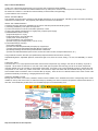
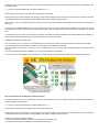
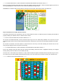
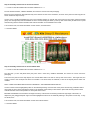
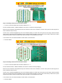
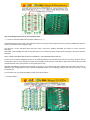
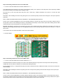
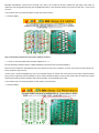
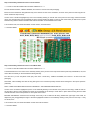
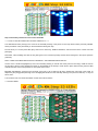
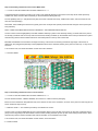
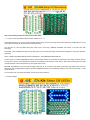
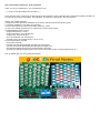
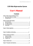
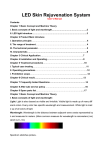
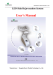
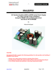
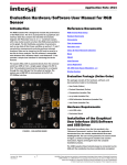
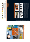
groLEDs: Computer Controllable, Adjustable Broad Spectrum, High Brightness "grow 50-LEDs-lamp" Kit PART NO. 2259817 The groLEDs kit offers an economical, versatile, safe, efficient, and easy-to-use alternative to traditional and commercial-grade Grow Lamp/Light products. BRIGHT: The three different colors of LEDs all include high luminosity intensity ratings measured in candelas (cd) instead of normal LED millicandela (mcd) ratings. The blue LEDs emit 57cd (57,000mcd), the white LEDs emit 80cd (80,000mcd), and the red LEDs emit 80cd (80,000mcd), when they are powered at their nominal operating voltage. The equivalent light output is that of (very bright) 217 (standard) candles when all LEDs are lit. When the kit is 'for sale' the Web Page will include an additional document, the User's Manual, which includes performance data, listing lux and footcandle values for various combinations of LEDs (red, white, and blue) at different voltage levels. The "groLEDs 'lit' photographs" picture (with this overview) were all taken at the lowest light levels possible (very low input voltages) to prevent the 'blinding' of the camera. ADJUSTABLE SPECTRUM: Unlike many full spectrum grow light products, which attempt to provide some additional red and blue light energy mixed with the standard yellow/white, the groLEDs kit is designed to enable the user to specifically select the light color output based upon growing needs. The color combinations include: 1) OFF (emulating night-time darkness) 2) BLUE Only ON, or 3) RED Only ON, or 4) WHITE Only ON, or 5) BLUE and RED Only ON, or 6) BLUE and WHITE Only ON, or 7) RED and WHITE Only ON, or 8) BLUE and RED and WHITE all ON. This enables the user to emphasize the blue end of the spectrum when attempting to promote healthy vegetation growth, while the red end is used when enhancing the budding and flowering phases of growth, depending upon specific growth requirements. DIRECTIONALLY FOCUSED: Common grow lamps in the shape of (T5) Florescent Tubes or common incandescent shaped bulbs broadcast their light in almost all directions, requiring mirror-reflectors to aim the light where it is needed by the plants. LED Lamps with narrow beam widths aim their light like spot lights right where it is needed by the plants. EASILY CONTROLLED: Most grow lamps, including many hi-tech LED lamp fixtures, only provide on-off capability. The groLEDs kit is designed so that each bank of colors (blue, white, and red) can be individually controlled, manually, or automatically via (computer-controlled) relay contacts, or both. This enables the user to control the spectrum and the time that light is on versus off, changing as the growing cycles change on a per-plant basis, if desired. POWER-SAFE: Mixing water and 115VAC never seemed like a good idea in any kind of growing environment. Nearly every grow light available, including most LED grow lamps, are powered by 115VAC, whether by a power cord that plugs into a nearby socket, or one that screws into a lamp socket wired for 115VAC. The groLEDs kit is designed to be run from +5VDC, enabling the user to safely use water near the groLEDs kit fixture without fear of electrocution. The user places the 5V power supply in a safe dry location remote from the growing (watering) area. Again, the "User Manual" will list the light output values and the operating current levels for a broad range of operating voltages, from about +3.0V up to over +5.5V. INEXPENSIVE: Compared to all other grow light solutions, the groLEDs kit is very inexpensive. Not including the printed circuit board and optional components, the Jameco catalog list-price for all 50 LEDs and their current limiters is just $21.45. Many groLEDs kits can be powered from a single, extremely inexpensive, ($15.00 common) Computer (tower) power supply. Because these power supplies source high current levels for both +3.3V and +5.0V, relay control of light levels and colors is very simple to implement. RELIABLE: LEDs have a life-cycle measured in tens-of-thousands-of hours, or many years; significantly longer than any other grow-light solution. Many commercially available 115VAC powered LED Grow bulbs include integrated AC-to-DC converters to create the proper power parameters for powering the LEDs within the bulb-fixture. These converters, being active electronics subjected to relatively high-heat conditions are prone to fail long before the actual light-emitting-diodes themselves. The groLEDs kit uses only passive components, making it much more dependable for many years of service. Unlike most Christmas LED strings, if and when a LED fails on the groLEDs kit, all the other LEDs remain lit without changing their intensities. ADJUSTABLE BRIGHTNESS: Since the groLEDs kit is completely passive, it is possible for the user to vary the light intensity, as needed, by varying the +5V input (down to +3.0V up to about +5.5V), to decrease or increase the brightness level, as needed for specific growing requirements. Details about these voltage levels, and the overall power requirements, are included in the "User Manual" for this kit. THRU-HOLE ONLY: The small 1.95" x 2.6" 2-layer printed circuit board uses thru-hole components only, making it a kit that can be built by any level of expertise. All 50 LEDs are mounted on one side of the board (see the picture with this overview), and all of the other components, including optional ones, are mounted on the backside of the board. Since this is not a typical assembly process to include thru-hole components on both sides of a printed circuit board, the instructions walk the kit-builder through the process to ensure reliable solder connections and no scorched LEDs (or fingers). There are four 0.2" diameter holes in each of the corners of the groLEDs kit assembly for mounting, or hanging the fixture for usage. WHY: My wife and live in the woods where consistent growing (sun) light is unheard of, making it difficult to start new plants, and even to keep mature plants growing properly during the winter. We have tried many artificial light sources; all of them with various short-comings; most of them extremely expensive. Necessity is the Mother of Invention. I hope that you enjoy the fruits of this labor. WARNING: If you are unsure of the dangers involved with your particular project, consult with someone who is experienced. Always wear eye protection and gloves. FAILURE TO INITIATE AND FOLLOW YOUR OWN SAFETY PROCEDURES MAY RESULT IN BODILY INJURY OR DEATH! Time Required: 3-4 hours, depending upon depending on experience Experience Level: Beginner Required tools and parts: Soldering iron and solder Wire cutters Needle nose pliers OPTIONAL COMPONENTS: (details later) 1) 5Vdc 2Amp power supply (see User Manual for more details and options) 2) 3 SPDT Slide Switches (Jameco #109171) for on-board on-off switches, on the backside. 3) 2-position Terminal Block (Jameco #TBD) for on-board wire-to-board terminal block connection, on the backside. Bill of Materials: Qty Jameco SKU Component Name 30 2193889 T1 3/4 5mm Clear Lens Blue LED 1900mcd 468nm 10 2174881 3mm 8000mcd White LED with Diffused Lens 10 2203813 LED Ultra Red Water Clear T1 3/4" 8000mcd 635Nm 1.7Vf 20 View Angle 10 690620 Resistor Carbon Film 100 Ohm 1/4 Watt 5% (In Bags of 10) 40 690566 Resistor Carbon Film 56 Ohm 1/4 Watt 5% (Bag of 10) Step 1: General Introduction In just 5.072 of Printed Circuit Board area, (up to) 104 thru-hole components will be installed: 50 LEDs in 3 colors in 2 different sizes will be installed on the top side (shown at bottom center of picture for this step); and, 50 resistors in 2 values in 1 size will be mounted vertically on the back side; with (optionally): 3 power switches and 1 connector. ABOUT THIS DOCUMENT: This particular document ONLY presents a brief INTRO (introduction) to the groLEDs kit, followed by ONLY the ASSY (assembly) instructions for building the kit. The (separate) User's Manual contains more information. ABOUT THE "USER's MANUAL": A separate document (also down-loadable from the Jameco web site) includes the following topics: 1) Assembly (installation) of the optional components 2) Control Connections for manual or automatic operations, or both. 3) How to wire multiple groLEDs kits to a single (tower) computer power supply. 4) PERFORMANCE data, including: a) light level outputs in Lux (for); b) light level output in Foot-Candles (for); c) input power current levels (for); d) for seven different color combinations; e) all with varying input voltage levels (+3.0V to +5.5V). 5) Technical Drawings, including: a) annotated schematic b) Printed Circuit Board (black/white photoplot) Top Copper layer c) Printed Circuit board (black/white photoplot) Bottom Copper Layer d) Assembly Drawings for both the top and the bottom of the board e) Printed Circuit Board Statistics (size of board, number and sizes of holes, trace/space dimensions, etc.) The groLEDs kit 'overview' discuses (not repeated here) important features and functions, including: Adjustable Brightness, Adjustable Spectrum, Directional Light Focus, Ease of Control, Safety, Low Cost, and Reliability, to name a few. THRU-HOLE ONLY: The small 1.95" x 2.6" 2-layer printed circuit board uses thru-hole components only, making it a kit that can be built by any level of expertise. All 50 LEDs are mounted on one side of the board (see the picture with this step), and all of the other components, including optional ones, are mounted on the backside of the board. Since this is not a typical assembly process to include thru-hole components on both sides of a printed circuit board, the instructions steps that follow walk the kit-builder through the process to ensure reliable solder connections and no scorched LEDs (or fingers). There are four 0.2" diameter holes in each of the corners of the groLEDs kit assembly for mounting, or hanging the fixture for usage. GENERAL ASSEMBLY FLOW: Moving from the center of the board, outwards, resistors will be installed on the backside before their corresponding LEDs will be installed on the top side of the board, to ensure that the (hot) soldering iron does not melt the temperature sensitive dome-lenses of the LEDs. More details are provided in the next 3 INTRO steps prior to actual assembly work. Step 2: Introduction to the Footprints The printed circuit board for the groLEDs kit uses four unique shapes and sizes of solder-hole-pads for assisting the kit-builder in the assembly process. ***** LOOK AT THE PICTURE FOR THIS STEP CAREFULLY ***** All 50 resistors are mounted on the back side of the printed circuit board. All 50 resistors are mounted vertically, with the body of the resistor residing over the larger round pad (as shown), and the flying lead, in parallel with the body of the resistor, being installed in the smaller octagonal pad (as shown). All 50 LEDs (3 colors in 2 different sizes) are mounted on the top side of the printed circuit board (the side with the white silkscreen print on it). All 50 LEDs are installed identically, with the anode lead (the longer of the two leads) being installed in the round hole, and the cathode lead (the shorter of the two leads, AND the lead closest to the flat spot on the body of the LED) being installed in the square hole. For each resistor-and-LED pair of components, the resistor is installed and soldered PRIOR to the LED's installation and soldering, in order to ensure that the hot soldering iron does NOT melt the lens (body) of the LED. ASSEMBLY GENERAL ORDER NOTE: Task a) a resistor (row, or group in a row) is installed on the back side of the board, bending the leads on the top side for retention. Task b) the leads for all of the resistors installed in task a (above) are soldered, and trimmed. Task c) the leads of a LED (row, or group in a row) is installed on the top side of the board, bending the leads on the back side for retention. Task d) the leads for all the LEDs installed in task c (above) are soldered, and trimmed. Then the next rows are installed, from the center row, outward, until all 100 components (50 resistors and 50 LEDs) are installed. Step 3: Introduction to the Resistors and their locations The printed circuit board for the groLEDs kit uses two unique shapes and sizes of solder-hole-pads for assisting the kit-builder in properly installing the 50 resistors. ***** LOOK AT THE PICTURE FOR THIS STEP CAREFULLY ***** All 50 resistors are mounted on the back side of the printed circuit board. All 50 resistors are mounted vertically, with the body of the resistor residing over the larger round pad (as shown), and the flying lead, in parallel with the body of the resistor, being installed in the smaller octagonal pad (as shown). There are two different values of resistors: 1) 56ohms located at 40 different positions on the backside of the board; and, 2) 100ohms located at just 10 positions on the backside of the board. ***** IT IS VERY IMPORTANT TO GET THE RIGHT RESISTORS MOUNTED IN THE RIGHT HOLES ***** Each of the ASSY (assembly) steps that follow involved with installing resistors will depict a similar assembly diagram (as shown for this step) highlighting the correct locations for the resistors' assembly for that given step. REMEMBER to install the resistor's body (lead) into the larger of the two pads, with the flying lead in the smaller one. Step 4: Introduction to the LEDs and their locations The printed circuit board for the groLEDs kit uses two unique shapes and sizes of solder-hole-pads for assisting the kit-builder in properly installing the 3 different colors in 2 different sizes of LEDs. ***** LOOK AT THE PICTURE FOR THIS STEP CAREFULLY ***** All 50 LEDs are installed identically, with the anode lead (the longer of the two leads) being installed in the round hole, and the cathode lead (the shorter of the two leads, AND the lead closest to the flat spot on the body of the LED) being installed in the square hole. All 50 LEDs are oriented in the same direction so that the flat side of the body of the LED, indicating the Cathode Lead, are ALL facing the right edge (as shown in the picture for this step). ***** IT IS VERY IMPORTANT TO GET THE RIGHT LEDs MOUNTED IN THE RIGHT HOLES ***** Each of the assembly steps that follow that are involved with installing LEDs will include a highlighted assembly view diagram showing exactly where the LEDs are to be installed, per step. One other note: All 50 LEDs have a clear lens, so they do NOT look like the picture associated with this step when they are not lit. As a matter of fact, the Red and Blue LEDs look identical when not lit; so be careful not to mix them up during your assembly work. ********** TURN ON YOUR SOLDERING IRON ********** Step 5: Assembly instructions for the first 8 resistors ***** LOOK AT THE PICTURE FOR THIS STEP CAREFULLY ***** Find the 56ohms resistors, JAMECO #690566, and remove 8 of them from their packaging. Bend one of the leads down alongside the body of the resistor for each of the 8 resistors, as shown in the picture for this step (and as shown in detail in steps 2 and 3). At each of the 8 locations highlighted (in red on the assembly drawing on the left side of the picture for this step), install the resistor (body over the large hole) from the backside of the PC board, bending the leads (on the top side of the board) to retain them in place while ensuring that the resistors maintain their vertical orientation on the backside of the board. Turn the board over, and solder both leads of each resistor, at all 8 locations. >>> SAFETY NOTE Step 6: Assembly instructions for the first 8 Blue LEDs ***** LOOK AT THE PICTURE FOR THIS STEP CAREFULLY ***** Find the 5mm (T-1-3/4 size) Blue LEDs (they each have a clear lens), JAMECO #2193889, and remove 8 of them from their packaging. The inset in the picture for this step depicts one of these Blue LEDs on its side on the top side of the board. The longer lead, the Anode, is close to the round pad into which it is installed. The shorter lead, the Cathode, is close to the square pad into which it is installed. NOTE: THESE LEDS MUST BE INSTALLED CORRECTLY FOR PROPER FUNCTIONALITY. At each of the 8 locations highlighted (in blue on the assembly drawing on the left side of the picture for this step), install the LED on the top side of the PC board, bending the leads (on the backside of the board) to retain them in place while ensuring that the LEDs maintain their flat-on-the-board position on the top side of the board. BEFORE SOLDERING: ensure that the flat edge of the body of all 8 LEDs are all facing towards the right edge of the board, as depicted by the (exaggerated) flat edge of the blue highlighted locations in the assembly drawing in the picture for this step. If they are all OK, then... Turn the board over, and solder both leads of each LED at all 8 locations. >>> SAFETY NOTE Step 7: Assembly instructions for the next 5 resistors ***** LOOK AT THE PICTURE FOR THIS STEP CAREFULLY ***** Find the 100ohms resistors, JAMECO #690620, and remove 5 of them from their packaging. Bend one of the leads down alongside the body of the resistor for each of the 5 resistors, as shown in the picture for this step (and as shown in detail in steps 2 and 3). At each of the 5 locations highlighted (in red on the assembly drawing on the left side of the picture for this step), install the resistor (body over the large hole) from the backside of the PC board, bending the leads (on the top side of the board) to retain them in place while ensuring that the resistors maintain their vertical orientation on the backside of the board. Turn the board over, and solder both leads of each resistor, at all 5 locations. >>> SAFETY NOTE Step 8: Assembly instructions for the next 9 resistors ***** LOOK AT THE PICTURE FOR THIS STEP CAREFULLY ***** Find the 56ohms resistors, JAMECO #690566, and remove 9 of them from their packaging. Bend one of the leads down alongside the body of the resistor for each of the 9 resistors, as shown in the picture for this step (and as shown in detail in steps 2 and 3). At each of the 9 locations highlighted (in red on the assembly drawing on the left side of the picture for this step), install the resistor (body over the large hole) from the backside of the PC board, bending the leads (on the top side of the board) to retain them in place while ensuring that the resistors maintain their vertical orientation on the backside of the board. Turn the board over, and solder both leads of each resistor, at all 9 locations. >>> SAFETY NOTE Step 9: Assembly instructions for the next 4 Blue LEDs ***** LOOK AT THE PICTURE FOR THIS STEP CAREFULLY ***** The dashed-blue box in the center of the assembly drawing in the picture for this step shows where previously installed blue LEDs are already on the board before starting this step. Find the 5mm (T-1-3/4 size) Blue LEDs (they each have a clear lens), JAMECO #2193889, and remove 4 of them from their packaging. Remember, when installing the LEDs the long lead goes in the round hole (Anode) and the shorter lead goes in the square pad hole (Cathode) NOTE: THESE LEDS MUST BE INSTALLED CORRECTLY FOR PROPER FUNCTIONALITY. At each of the 4 locations highlighted (in blue on the assembly drawing on the left side of the picture for this step), install the LED on the top side of the PC board, bending the leads (on the backside of the board) to retain them in place while ensuring that the LEDs maintain their flat-on-the-board position on the top side of the board. BEFORE SOLDERING: ensure that the flat edge of the body of all 4 LEDs are all facing towards the right edge of the board, as depicted by the (exaggerated) flat edge of the blue highlighted locations in the assembly drawing in the picture for this step. If they are all OK, then... Turn the board over, and solder both leads of each LED at all 4 locations. >>> SAFETY NOTE Step 10: Assembly instructions for the first 5 Red LEDs ***** LOOK AT THE PICTURE FOR THIS STEP CAREFULLY ***** The dashed-blue boxes (mostly) in the center of the assembly drawing in the picture for this step shows where previously installed blue LEDs are already on the board before starting this step. Find the 5mm (T-1-3/4 size) Red LEDs (they each have a clear lens), JAMECO #2203813, and remove 5 of them from their packaging. Remember, when installing the LEDs the long lead goes in the round hole (Anode) and the shorter lead goes in the square pad hole (Cathode) NOTE: THESE LEDS MUST BE INSTALLED CORRECTLY FOR PROPER FUNCTIONALITY. At each of the 5 locations highlighted (in red on the assembly drawing on the left side of the picture for this step), install the LED on the top side of the PC board, bending the leads (on the backside of the board) to retain them in place while ensuring that the LEDs maintain their flat-on-the-board position on the top side of the board. BEFORE SOLDERING: ensure that the flat edge of the body of all 5 LEDs are all facing towards the right edge of the board, as depicted by the (exaggerated) flat edge of the red highlighted locations in the assembly drawing in the picture for this step. If they are all OK, then... Turn the board over, and solder both leads of each LED at all 5 locations. >>> SAFETY NOTE Step 11: Assembly instructions for the first 5 White LEDs ***** LOOK AT THE PICTURE FOR THIS STEP CAREFULLY ***** The dashed blue and red boxes (mostly) in the center of the assembly drawing in the picture for this step shows where previously installed blue and red LEDs are already on the board before starting this step. Find the [smaller] 3mm (T-1 size) White LEDs (they each have a diffused clear lens), JAMECO #2174881, and remove 5 of them from their packaging. Remember, when installing the LEDs the long lead goes in the round pad hole (Anode) and the shorter lead goes in the square pad hole (Cathode) NOTE: THESE LEDS MUST BE INSTALLED CORRECTLY FOR PROPER FUNCTIONALITY. At each of the 5 locations highlighted (in a smaller red/blue LED body symbol on the assembly drawing on the left side of the picture for this step), install the LED on the top side of the PC board, bending the leads (on the backside of the board) to retain them in place while ensuring that the LEDs maintain their flat-on-the-board position on the top side of the board. BEFORE SOLDERING: ensure that the flat edge of the body of all 5 LEDs are all facing towards the right edge of the board, as depicted by the (exaggerated) flat edge of the highlighted locations in the assembly drawing in the picture for this step. If they are all OK, then... Turn the board over, and solder both leads of each LED at all 5 locations. >>> SAFETY NOTE Step 12: Assembly instructions for the last 5 100ohms resistors ***** LOOK AT THE PICTURE FOR THIS STEP CAREFULLY ***** Find the remaining 100ohms resistors, JAMECO #690620, and remove them from their packaging. Bend one of the leads down alongside the body of the resistor for each of the 5 resistors, as shown in the picture for this step (and as shown in detail in steps 2 and 3). At each of the 5 locations highlighted (in red on the assembly drawing on the left side of the picture for this step), install the resistor (body over the large hole) from the backside of the PC board, bending the leads (on the top side of the board) to retain them in place while ensuring that the resistors maintain their vertical orientation on the backside of the board. Turn the board over, and solder both leads of each resistor, at all 5 locations. >>> SAFETY NOTE Step 13: Assembly instructions for the next 9 resistors ***** LOOK AT THE PICTURE FOR THIS STEP CAREFULLY ***** Find the 56ohms resistors, JAMECO #690566, and remove 9 of them from their packaging. Bend one of the leads down alongside the body of the resistor for each of the 9 resistors, as shown in the picture for this step (and as shown in detail in steps 2 and 3). At each of the 9 locations highlighted (in red on the assembly drawing on the left side of the picture for this step), install the resistor (body over the large hole) from the backside of the PC board, bending the leads (on the top side of the board) to retain them in place while ensuring that the resistors maintain their vertical orientation on the backside of the board. Turn the board over, and solder both leads of each resistor, at all 9 locations. >>> SAFETY NOTE Step 14: Assembly instructions for the next 4 Blue LEDs ***** LOOK AT THE PICTURE FOR THIS STEP CAREFULLY ***** The dashed-blue box in the center of the assembly drawing in the picture for this step shows where previously installed blue, red, and white LEDs are already on the board before starting this step. Find the 5mm (T-1-3/4 size) Blue LEDs (they each have a clear lens), JAMECO #2193889, and remove 4 of them from their packaging. Remember, when installing the LEDs the long lead goes in the round hole (Anode) and the shorter lead goes in the square pad hole (Cathode) NOTE: THESE LEDS MUST BE INSTALLED CORRECTLY FOR PROPER FUNCTIONALITY. At each of the 4 locations highlighted (in blue on the assembly drawing on the left side of the picture for this step), install the LED on the top side of the PC board, bending the leads (on the backside of the board) to retain them in place while ensuring that the LEDs maintain their flat-on-the-board position on the top side of the board. BEFORE SOLDERING: ensure that the flat edge of the body of all 4 LEDs are all facing towards the right edge of the board, as depicted by the (exaggerated) flat edge of the blue highlighted locations in the assembly drawing in the picture for this step. If they are all OK, then... Turn the board over, and solder both leads of each LED at all 4 locations. >>> SAFETY NOTE Step 15: Assembly instructions for the last 5 Red LEDs ***** LOOK AT THE PICTURE FOR THIS STEP CAREFULLY ***** The dashed-blue boxes (mostly) in the center of the assembly drawing in the picture for this step shows where previously installed LEDs (of all three colors) are already on the board before starting this step. Find the 5mm (T-1-3/4 size) Red LEDs (they each have a clear lens), JAMECO #2203813, and remove the last 5 of them from their packaging. Remember, when installing the LEDs the long lead goes in the round hole (Anode) and the shorter lead goes in the square pad hole (Cathode) NOTE: THESE LEDS MUST BE INSTALLED CORRECTLY FOR PROPER FUNCTIONALITY. At each of the 5 locations highlighted (in red on the assembly drawing on the left side of the picture for this step), install the LED on the top side of the PC board, bending the leads (on the backside of the board) to retain them in place while ensuring that the LEDs maintain their flat-on-the-board position on the top side of the board. BEFORE SOLDERING: ensure that the flat edge of the body of all 5 LEDs are all facing towards the right edge of the board, as depicted by the (exaggerated) flat edge of the red highlighted locations in the assembly drawing in the picture for this step. If they are all OK, then... Turn the board over, and solder both leads of each LED at all 5 locations. >>> SAFETY NOTE Step 16: Assembly instructions for the last 5 White LEDs ***** LOOK AT THE PICTURE FOR THIS STEP CAREFULLY ***** The dashed blue and red boxes (mostly) in the center of the assembly drawing in the picture for this step shows where previously installed red, white, and blue LEDs are already on the board before starting this step. Find the [smaller] 3mm (T-1 size) White LEDs (they each have a diffused clear lens), JAMECO #2174881, and remove the last 5 of them from their packaging. Remember, when installing the LEDs the long lead goes in the round pad hole (Anode) and the shorter lead goes in the square pad hole (Cathode) NOTE: THESE LEDS MUST BE INSTALLED CORRECTLY FOR PROPER FUNCTIONALITY. At each of the 5 locations highlighted (in a smaller red/blue LED body symbol on the assembly drawing on the left side of the picture for this step), install the LED on the top side of the PC board, bending the leads (on the backside of the board) to retain them in place while ensuring that the LEDs maintain their flat-on-the-board position on the top side of the board. BEFORE SOLDERING: ensure that the flat edge of the body of all 5 LEDs are all facing towards the right edge of the board, as depicted by the (exaggerated) flat edge of the highlighted locations in the assembly drawing in the picture for this step. If they are all OK, then... Turn the board over, and solder both leads of each LED at all 5 locations. >>> SAFETY NOTE Step 17: Assembly instructions for the next 9 resistors ***** LOOK AT THE PICTURE FOR THIS STEP CAREFULLY ***** Find the 56ohms resistors, JAMECO #690566, and remove 14 of them from their packaging. Bend one of the leads down alongside the body of the resistor for each of the 9 resistors, as shown in the picture for this step (and as shown in detail in steps 2 and 3). *** SPECIAL NOTE *** Two resistors (R3 & R21) are rotated from normal... At each of the 14 locations highlighted (in red on the assembly drawing on the left side of the picture for this step), install the resistor (body over the large hole) from the backside of the PC board, bending the leads (on the top side of the board) to retain them in place while ensuring that the resistors maintain their vertical orientation on the backside of the board. Turn the board over, and solder both leads of each resistor, at all 14 locations. >>> SAFETY NOTE Step 18: Assembly instructions for the last 14 Blue LEDs ***** LOOK AT THE PICTURE FOR THIS STEP CAREFULLY ***** The dashed-blue box in the center of the assembly drawing in the picture for this step shows where previously installed blue, red, and white LEDs are already on the board before starting this step. Find the 5mm (T-1-3/4 size) Blue LEDs (they each have a clear lens), JAMECO #2193889, and remove 14 of them from their packaging. Remember, when installing the LEDs the long lead goes in the round hole (Anode) and the shorter lead goes in the square pad hole (Cathode) NOTE: THESE LEDS MUST BE INSTALLED CORRECTLY FOR PROPER FUNCTIONALITY. At each of the 14 locations highlighted (in blue on the assembly drawing on the left side of the picture for this step), install the LED on the top side of the PC board, bending the leads (on the backside of the board) to retain them in place while ensuring that the LEDs maintain their flat-on-the-board position on the top side of the board. BEFORE SOLDERING: ensure that the flat edge of the body of all 14 LEDs are all facing towards the right edge of the board, as depicted by the (exaggerated) flat edge of the blue highlighted locations in the assembly drawing in the picture for this step. If they are all OK, then... Turn the board over, and solder both leads of each LED at all 14 locations. >>> SAFETY NOTE Step 19: Assembly instructions; Some Final Notes TASK: Turn off your soldering iron; you are finished (for now). ***** LOOK AT THE PICTURE FOR THIS STEP ***** The bottom left corner of the picture for this step shows what the bottom edge of the back side of the board assembly looks like if all four optional components are installed. Their installation and operation is discussed in the User's Manual. ABOUT THE "USER's MANUAL": A separate document (also down-loadable from the Jameco web site) includes the following topics: 1) Assembly (installation) of the optional components 2) Control Connections for manual or automatic operations, or both. 3) How to wire multiple groLEDs kits to a single (tower) computer power supply. 4) PERFORMANCE data, including: a) light level outputs in Lux (for); b) light level output in Foot-Candles (for); c) input power current levels (for); d) for seven different color combinations; e) all with varying input voltage levels (+3.0V to +5.5V). 5) Technical Drawings, including: a) annotated schematic b) Printed Circuit Board (black/white photoplot) Top Copper layer c) Printed Circuit board (black/white photoplot) Bottom Copper Layer d) Assembly Drawings for both the top and the bottom of the board e) Printed Circuit Board Statistics (size of board, number and sizes of holes, trace/space dimensions, etc.) Now, go GROW with your new groLEDs kit assembly.