1
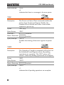
Precision Current Shunt Meter
PCS-1000
USER MANUAL
GW INSTEK PART NO. 82CS-1K000EB1
ISO-9001 CERTIFIED MANUFACTURER
This manual contains proprietary information, which is protected by
copyright. All rights are reserved. No part of this manual may be
photocopied, reproduced or translated to another language without
prior written consent of Good Will company.
The information in this manual was correct at the time of printing.
However, Good Will continues to improve products and reserves the
rights to change specification, equipment, and maintenance
procedures at any time without notice.
Good Will Instrument Co., Ltd.
No. 7-1, Jhongsing Rd., Tucheng Dist., New Taipei City 236, Taiwan.
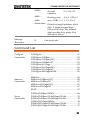
Table of Contents
Table of Contents
SAFETY INSTRUCTIONS ................................................... 4
GETTING STARTED ........................................................... 8
PCS-1000 Overview ................................ 9
Appearance .......................................... 11
OPERATION .................................................................... 18
Set Up .................................................. 19
Basic Operation ................................... 25
COMMUNICATION INTERFACE ...................................... 42
Interface Configuration ........................ 44
Command Syntax ................................. 56
Command List ..................................... 59
Status Registers ................................... 86
Error Messages .................................... 87
APPENDIX ...................................................................... 88
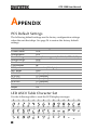
PCS Default Settings ............................ 88
LED ASCII Table Character Set ............. 88
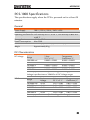
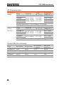
PCS-1000 Specifications ....................... 89
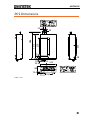
PCS Dimensions .................................. 91
Declaration of Conformity .................... 92
INDEX............................................................................. 93
3
PCS-1000 User Manual
SAFETY INSTRUCTIONS
This chapter contains important safety
instructions that you must follow during
operation and storage. Read the following before
any operation to insure your safety and to keep
the instrument in the best possible condition.
Safety Symbols
These safety symbols may appear in this manual or on the
instrument.
WARNING
Warning: Identifies conditions or practices that
could result in injury or loss of life.
CAUTION
Caution: Identifies conditions or practices that
could result in damage to the instrument or to
other properties.
DANGER High Voltage
Attention Refer to the Manual
Protective Conductor Terminal
Earth (ground) Terminal
Do not dispose electronic equipment as unsorted
municipal waste. Please use a separate collection
facility or contact the supplier from which this
instrument was purchased.
4
SAFETY INSTRUCTIONS
Safety Guidelines
General
Guideline
CAUTION
Do not place any heavy object on the
instrument.
Avoid severe impact or rough handling that
leads to damaging the instrument.
Do not discharge static electricity to the
instrument.
Use only mating connectors, not bare wires, for
the terminals.
Do not block the cooling fan opening.
Do not disassemble the instrument unless you
are qualified.
(Measurement categories) EN 61010-1:2001 specifies the
measurement categories and their requirements as follows. The
instrument falls under category II (600VAC).
Measurement category IV is for measurement performed at the
source of low-voltage installation.
Measurement category III is for measurement performed in the
building installation.
Measurement category II is for measurement performed on the
circuits directly connected to the low voltage installation.
Measurement category I is for measurements performed on
circuits not directly connected to Mains.
Power Supply
WARNING
Cleaning the
Instrument
AC Input voltage range:
100V/120V/220V/240V ±10% (selectable range)
Frequency: 50/60Hz
To avoid electrical shock connect the protective
grounding conductor of the AC power cord to
an earth ground.
Disconnect the power cord before cleaning.
Use a soft cloth dampened in a solution of mild
detergent and water. Do not spray any liquid.
Do not use chemicals containing harsh material
such as benzene, toluene, xylene, and acetone.
5
PCS-1000 User Manual
Operation
Environment
Location: Indoor, no direct sunlight, dust free,
almost non-conductive pollution (Note below)
Relative Humidity: Full accuracy to 80% RH, at
40°C
Altitude: < 2000m
Temperature: 0°C to 50°C
(Pollution Degree) EN 61010-1:2001 specifies the pollution degrees
and their requirements as follows. The instrument falls under
degree 2.
Pollution refers to “addition of foreign matter, solid, liquid, or
gaseous (ionized gases), that may produce a reduction of dielectric
strength or surface resistivity”.
Pollution degree 1: No pollution or only dry, non-conductive
pollution occurs. The pollution has no influence.
Pollution degree 2: Normally only non-conductive pollution
occurs. Occasionally, however, a temporary conductivity caused
by condensation must be expected.
Pollution degree 3: Conductive pollution occurs, or dry, nonconductive pollution occurs which becomes conductive due to
condensation which is expected. In such conditions, equipment
is normally protected against exposure to direct sunlight,
precipitation, and full wind pressure, but neither temperature
nor humidity is controlled.
Storage
environment
Disposal
6
Location: Indoor
Temperature: -40°C to 70°C
Relative Humidity: <90%
Do not dispose this instrument as unsorted
municipal waste. Please use a separate collection
facility or contact the supplier from which this
instrument was purchased. Please make sure
discarded electrical waste is properly recycled to
reduce environmental impact.
SAFETY INSTRUCTIONS
Power cord for the United Kingdom
When using the instrument in the United Kingdom, make sure the
power cord meets the following safety instructions.
NOTE: This lead/appliance must only be wired by competent persons
WARNING: THIS APPLIANCE MUST BE EARTHED
IMPORTANT: The wires in this lead are coloured in accordance with the
following code:
Green/ Yellow:
Earth
Blue:
Neutral
Brown:
Live (Phase)
As the colours of the wires in main leads may not correspond with
the coloured marking identified in your plug/appliance, proceed
as follows:
The wire which is coloured Green & Yellow must be connected to
the Earth terminal marked with either the letter E, the earth symbol
or coloured Green/Green & Yellow.
The wire which is coloured Blue must be connected to the terminal
which is marked with the letter N or coloured Blue or Black.
The wire which is coloured Brown must be connected to the
terminal marked with the letter L or P or coloured Brown or Red.
If in doubt, consult the instructions provided with the equipment
or contact the supplier.
This cable/appliance should be protected by a suitably rated and
approved HBC mains fuse: refer to the rating information on the
equipment and/or user instructions for details. As a guide, a cable
of 0.75mm2 should be protected by a 3A or 5A fuse. Larger
conductors would normally require 13A types, depending on the
connection method used.
Any exposed wiring from a cable, plug or connection that is
engaged in a live socket is extremely hazardous. If a cable or plug is
deemed hazardous, turn off the mains power and remove the cable,
any fuses and fuse assemblies. All hazardous wiring must be
immediately destroyed and replaced in accordance to the above
standard.
7
PCS-1000 User Manual
GETTING STARTED
This chapter describes the instrument in a
nutshell, including its main features and front /
rear panel introduction.
PCS-1000 Overview ........................................................... 9
Main Features .............................................................................................. 9
Accessories ................................................................................................ 10
Appearance ..................................................................... 11
Front Panel ................................................................................................ 11
Rear Panel .................................................................................................. 16
8
GETTING STARTED
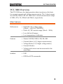
PCS-1000 Overview
The PCS-1000 uses five high-precision shunt resistors as the basis
for accurate current and voltage measurements. The 5 shunt ranges
are 0.001Ω, 0.01Ω, 0.1Ω, 1Ω, 10Ω with a current measurement range
of 300A, 30A, 3A, 300mA and 30mA, respectively.
Main Features
Performance
Features
Interface
Wide DC/AC voltage range
(200mV ~ 600VAC/1000VDC)
Wide AC/DC current range (30mA ~ 300A)
Low drift at all ranges
Low temperature coefficients
Shunts: 0.001Ω, 0.01Ω, 0.1Ω, 1Ω, 10Ω
Current Meter (6 1/2 digits current meter)
Voltage Meter (6 1/2 digits voltage meter)
Current Monitor
Voltage and current can be measured at the
same time.
USB
GPIB for SCPI commands
9
PCS-1000 User Manual
Accessories
Standard
Accessories
Part number
Description
Region dependant
User manual
Region dependant
Power cord
GTL-105A
Alligator clip test leads (3A
max): 1x red, 1x black
GTL-207
Banana plug test leads:
1x red, 1x black
GTL-240
USB Cable
PCS-001
Basic Accessory Kit:
Bolt HMS M8*16 x2
Nut hexagon M8*0.75P x2
Spring washer M8
8.4*13.7*1.5T x2
Plain washer M8
8.4*16*1.6T x2
Optional
Accessories
10
Part number
Description
GRA-419-J
Rack mount adapter (JIS)
GRA-419-E
Rack mount adapter (EIA)
GETTING STARTED
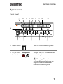
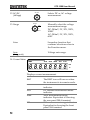
Appearance
Front Panel
7
14
8
9
10
11
12
15
CURRENT
RMT
ACA
DCA
13
VOLTAGE
300A
30A
Auto
PCS-1000
ERROR
ACV
DCV
Auto
mA
mV
A
Local
AC / DC
300A / 30A
6
V
3A Range
Func
AC / DC
Range
Auto
Auto
: Long Push
Func
POWER
Select
INPUT
Enter
INPUT
OUTPUT
INPUT
30A
3A
MAX
MAX
Current
Monitor
DC 1000V
AC 600V
MAX
1
1. Power Switch
2. AC/DC 30A
Terminal
( No Fuse )
( Fused )
2
3
CAT II 600V
4
5
Turn on or off the main power.
POWER
INPUT
30A
MAX
Accepts DC/AC. 30A maximum
current input.
( No Fuse )
Warning: The maximum
voltage difference between the
negative terminal and earth
cannot exceed 500Vpeak.
11
PCS-1000 User Manual
3. AC/DC 3A
Terminal
INPUT
3A
MAX
( Fused )
Accepts DC/AC. 3A maximum
current input. Internally, there is a
fuse which protects the instrument
from over current:
Fuse Rating: T3.5A, 600V
Note: If the fuse is damaged,
please contact your dealer or a
GW Instek service center to
replace the fuse.
Warning: The maximum
voltage difference between the
negative terminal and earth
cannot exceed 500Vpeak.
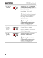
4. Current
Monitor
Sensor
5. AC/DC
Voltage
Terminal
OUTPUT
Current
Monitor
Current Monitor Output.
Range 0~300mV (0~full scale of
selected input range).
INPUT
DC 1000V
AC 600V
MAX
Accepts DC 1000V or AC 600V
maximum voltage input.
Warning: The maximum
voltage difference between the
negative terminal and earth
cannot exceed 500Vpeak.
12
GETTING STARTED
6. Local
Local
Func
Func
(long push)
7. ◄ Func ►
Local: Press to switch to local
mode.
AC / DC
Func
Func: Long push to enter the
Function menu. The Function
menu is used to configure the
instrument.
Local
Use the Func arrows keys to
scroll through each function
when in the Function menu.
AC / DC
Func
Func
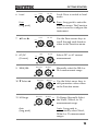
8. AC/DC
(Current)
Local
Selects DC or AC current
measurement.
AC / DC
Func
Func
9. 300A/30A
300A / 30A
3A Range
Auto
Manually select the 300A or
30A measurement range.
Select
10. ▼ Select ▲
300A / 30A
3A Range
Auto
Use the Select arrow keys to
edit parameter values when
in the Function menu.
Select
11. 3A Range
300A / 30A
3A Range
Auto
3A Range: Manually Select
the 30mA, 300mA, or 3A
measurement range.
Select
Auto
(long push)
Auto: Long push to
automatically select 30mA,
300mA or 3A measurement
ranges.
13
PCS-1000 User Manual
12. AC/DC
(Voltage)
Selects DC or AC voltage
measurement.
AC / DC
13. Range
Manually select the voltage
measurement range:
DC: 200mV, 2V, 20V, 200V,
1000V
AC: 200mV, 2V, 20V, 200V,
600V
Range
Auto
Enter
Enter
Secondary function that
confirms selections when in
the Function menu.
Auto
(long push)
Voltage auto range.
14. Current Meter
CURRENT
RMT
ACA
DCA 300A
30A
Auto
ERROR
mA
A
Displays current measurement.
RMT
ACA
DCA
300A
30A
14
The RMT icon will turn on when
the instrument is in remote mode.
AC current measurement mode
indicator.
DC current measurement mode
indicator.
300A measurement range
indicator. Equivalent to choosing
the rear panel 300A terminal.
30A measurement range indicator.
Equivalent to choosing the front
panel 30A terminal.
GETTING STARTED
Auto
mA
A
RRENT
DCA 300A
30A
15. Voltage Meter
Auto
Autorange indicator for the 30mA,
300mA and 3A ranges. If the
Autorange indicator is off, then
that indicates that the range has
been manually selected.
Milliamp unit indicator.
Ampere unit indicator.
VOLTAGE
ERROR
ACV
DCV
Auto
mA
mV
A
V
Displays voltage measurement.
ERROR
ACV
DCV
Auto
mV
V
Warning:
Indicates an interface error. The
SYSTem:ERRor? query can be
used to read back error messages.
See page 87 and 74 for details.
AC voltage measurement mode
indicator.
DC voltage measurement mode
indicator.
Autorange indicator. If the Auto
indicator is off, then that indicates
that the range has been manually
selected.
Millivolt unit indicator.
Volt unit indicator.
For the 3A, 30A and 300A terminals on the front and
rear panels, the maximum voltage difference
between the negative terminal and earth cannot
exceed 500Vpeak.
15
PCS-1000 User Manual
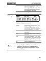
Rear Panel
17
18
19
INPUT
300A MAX.
( NO FUSE )
GPIB
LINE RATING
50 / 60 Hz
35VA MAX.
FUSE
LINE
T200mA
100VAC
120VAC
T100mA
220VAC
240VAC
SER.NO. LABEL
DISCONNECT POWER CORD
AND TEST LEADS BEFORE
REPLACING FUSE
16
100
120
220
16. Power Cord
Socket
20
240
Fuse Socket
Accepts the power cord.
Input: AC 100/120/220/240V
±10%
Line frequency: 50Hz/60Hz
Power: 35VA Max
Fuse rating: T200mA, 250V for
AC 100/120V; T100mA, 250V for
AC 220/240V
17. GPIB
Communicati
on Port
GPIB used for remote control.
18. USB
Communicati
on Port
USB B device port. Used for
remote control and firmware
update.
16
GETTING STARTED
19. AC/DC 300A
Terminal
20. Fan
INPUT
300A MAX.
( NO FUSE )
Accepts AC/DC.
300A maximum
current input.
Temperature controlled fan.
17
PCS-1000 User Manual
OPERATION
Set Up ............................................................................. 19
Power Up ................................................................................................... 19
Rack Mount ............................................................................................... 20
Wire Gauge Considerations ...................................................................... 21
Input Terminals ......................................................................................... 22
Basic Operation .............................................................. 25
Selecting AC/DC Current .......................................................................... 25
Selecting the Current Range...................................................................... 25
Selecting AC/DC Voltage........................................................................... 26
Selecting the Voltage Range ...................................................................... 27
Voltage Range Conversion Table .............................................................. 28
Crest Factor Table ..................................................................................... 29
Using the Current Monitor Output ........................................................... 30
How to Use the Function Menu ............................................................... 31
View the Software Version......................................................................... 33
Default Settings ......................................................................................... 34
Setting the USB-UART Baud Rate ............................................................. 35
Setting the GPIB Address .......................................................................... 36
Setting the AD Speed ................................................................................ 37
Setting the Averaging Mode...................................................................... 38
Setting the Averaging Number for the DCV/ACV/DCA/ACA .................. 39
Setting the Autozero Function .................................................................. 40
Beeper Settings.......................................................................................... 41
18
OPERATION
Set Up
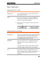
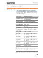
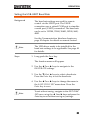
Power Up
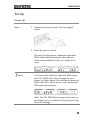
Steps
1. Connect the power cord to the rear panel
socket.
2. Press the power switch.
The unit will perform a calibration data and
ROM check and then display the software
version momentarily before it is ready to be
used.
CURRENT
RMT
Note
ACA
DCA 300A
VOLTAGE
30A
Auto
ERROR
ACV
DCV
Auto
mA
mV
A
V
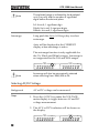
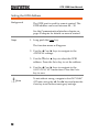
In the event the calibration data and ROM check
fails, CAL DATA FAIL will be displayed on the
screen, as shown below. If the calibration data and
ROM check fails, return the unit to an authorized
GW Instek service center.
CURRENT
RMT
ACA
DCA 300A
VOLTAGE
30A
Auto
ERROR
ACV
DCV
Auto
mA
mV
A
V
Note: The CAL DATA FAIL message will remain on
the display until it is cleared. Press any key to clear
the error message.
19
PCS-1000 User Manual
Rack Mount
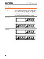
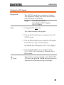
Background
GRA-419-E
GRA-419-J
20
The PCS-1000 has two types of the racks, GRA419-E and the GRA-419-J for the EIA and JIS
standards, respectively. Both types of the racks
are 2U height racks and can fit 1 or 2 units. See
the GRA-419 assembly manual for details.
OPERATION
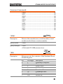
Wire Gauge Considerations
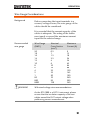
Background
Before connecting the input terminals to a
current/voltage source, the wire gauge of the
cables should be considered.
It is essential that the current capacity of the
cables is adequate. The rating of the cables
must equal or exceed the maximum current
input for the selected range.
Recommended
wire gauge
Wire Gauge
(AWG)
20
18
16
14
12
10
8
6
4
2
1
00
000
0000
WARNING
Nominal
Cross Section
(mm2)
0.5
1
1.5
2.5
4
6
10
16
25
32
50
70
95
120
Maximum
Current (A)
9
13
18
24
34
45
64
88
120
145
190
240
290
340
Withstand voltage wire recommendations
As the PCS-1000 is a CAT II instrument, please
ensure that the insulation capacity of the test
cables exceed the DUT output voltage when
performing current measurement.
21
PCS-1000 User Manual
Input Terminals
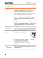
Background
There are 3 terminals for the 300A, 30A and
3A/300mA/30mA ranges, respectively.
The 300A range uses the rear panel terminals
and uses M8 crimped terminal cables.
The 30A range uses the 30A terminal and uses
M4 sized crimped terminal cables or banana
plugs.
The 3A input terminal uses standard banana
plugs (GW Instek part number GTL-105A). The
3A terminal supports 3A, 30mA and 300mA
ranges.
WARNING
Steps
Ensure any current or voltage sources are disabled
before connecting any cables to the PCS-1000.
1. Turn the power switch off.
POWER
Page 20
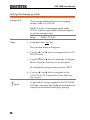
2. Connect the PCS-1000 in series
with the load and source. The
current monitor output can be
used in conjunction with a voltage
meter.
WARNING:
22
Do not short the positive or negative 3A, 30A and
300A terminals.
OPERATION
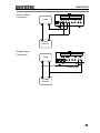
Current Meter
Connection
Load
+ current input
- current input
Power
Source
Voltage Meter
Connection
Load
+ voltage input
- voltage input
Power
Source
23
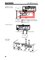
PCS-1000 User Manual
Voltage + Current
Meter Connection
Load
1
+A
+V
3
-V
-A
2
Power
Source
1 Measure voltage at load terminal
2 Measure voltage at source terminal
3 Measure current
Current Monitor
– current monitor
+ current monitor
DVM
Rear Panel
Terminals
24
OPERATION
Basic Operation
Selecting AC/DC Current
Background
Steps
AC or DC current can be measured when in
measurement mode.
1. Press the AC/DC key under the CURRENT
meter current display to toggle between AC
and DC current measurement.
2. The ACA or DCA indicator will be shown on
the display.
CURRENT
RMT
ACA
DCA 300A
VOLTAGE
30A
Auto
ERROR
ACV
DCV
Auto
mA
mV
A
V
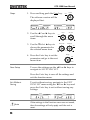
Selecting the Current Range
Background
There are 5 selectable current ranges. The range
can be manually or automatically selected.
Selecting a current range will also select the
corresponding the input terminal.
300A/30A
Press the 300/30A key to toggle between the
300A and 30A ranges (as indicated on the
display).
The 300A range will select the 300A terminal.
The 30A range will select the 30A terminal.
3A
Press the 3A Range key toggle between the
30mA, 300mA and 3A ranges. Selecting the 3A,
30mA or 300mA range will select the 3A
terminal.
25
PCS-1000 User Manual
Note
The selected range is indicated by the displayed
unit (A or mA) and the number of significant
digits before the decimal place:
3A: Unit=A; 1 significant digit
30mA: Unit=mA; 2 signicant digits
300mA: Uni=mA; 3 significant digits
Autorange
Long push the Auto (3A Range) key to select
autorange.
Auto will be displayed in the CURRENT
display when autorange is active.
The autorange function is only applicable for
the 3A, 30mA and 300mA ranges. Autorange is
not supported for the 30A and 300A ranges.
CURRENT
RMT
Note
ACA
DCA 300A
VOLTAGE
30A
Auto
ERROR
ACV
DCV
Auto
mA
mV
A
V
Autorange will also be automatically selected
when switching from 300A/30A to 3A.
Selecting AC/DC Voltage
Background
Steps
AC or DC voltage can be measured.
1. Press the AC/DC key under the VOLTAGE
meter display to toggle between AC and DC
voltage measurement.
2. The ACV or DCV indicator will be shown on
the display.
CURRENT
RMT
26
ACA
DCA 300A
VOLTAGE
30A
Auto
ERROR
ACV
DCV
Auto
mA
mV
A
V
OPERATION
Selecting the Voltage Range
Background
There are 5 selectable voltage ranges. The
range can be manually or automatically
selected.
Manual Ranges
Press the Range key to cycle between each
voltage range.
ACV:
DCV:
Note
200mV, 2V, 20V, 200V, 600V
200mV, 2V, 20V, 200V, 1000V
The selected range is indicated by the displayed
unit (V or mV) and the number of significant digits
before the decimal place:
200mV: Unit=mV; 3 significant digits
2V: Unit=V; 1 significant digit
20V: Unit=V; 2 significant digits
200V: Unit=V; 3 significant digits
AC 600V: Unit=V; 3 significant digits
DC 1000V: Unit=V; 4 significant digits
Autorange
Long push the Auto key to select autorange.
Auto will be displayed in the VOLTAGE
display when autorange is active.
CURRENT
RMT
ACA
DCA 300A
VOLTAGE
30A
Auto
ERROR
ACV
DCV
Auto
mA
mV
A
V
27
PCS-1000 User Manual
Voltage Range Conversion Table
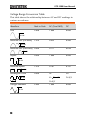
This table shows the relationship between AC and DC readings in
various waveforms.
Waveform
Peak to Peak
AC (True RMS)
DC
Sine
2.828
1.000
0.000
Rectified Sine (full wave) 1.414
0.435
0.900
0.771
0.636
2.000
1.000
0.000
1.414
0.707
0.707
2.000
2K
2D
K= ( D D 2)
D=X/Y
PK-PK
PK-PK
Rectified Sine (half wave) 2.000
PK-PK
Square
PK-PK
Rectified Square
PK-PK
Rectangular Pulse
X
PK-PK
Y
D=X/Y
Triangle Sawtooth
PK-PK
28
3.464
1.000
0.000
OPERATION
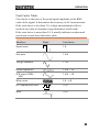
Crest Factor Table
Crest factor is the ratio of the peak signal amplitude to the RMS
value of the signal. It determines the accuracy of AC measurement.
If the crest factor is less than 3.0, voltage measurement will not
result in error due to dynamic range limitations at full scale.
If the crest factor is more than 3.0, it usually indicates an abnormal
waveform as seen from the below table.
Waveform
Shape
Crest factor
Square wave
1.0
Sine wave
1.414
Triangle sawtooth
1.732
Mixed frequencies
1.414 ~ 2.0
SCR output 100% ~
10%
1.414 ~ 3.0
White noise
3.0 ~ 4.0
AC Coupled pulse train
>3.0
Spike
>9.0
29
PCS-1000 User Manual
Using the Current Monitor Output
Background
The current monitor is used to measure the
voltage drop across the shunt resistors
manually.
The current monitor outputs the full scale
current input (for the selected range) as a
voltage of 0~300mV.
Shunt Values
Steps
Range
Shunt
30 mA
300 mA
3A
30 A
300 A
10Ω
1Ω
0.1Ω
0.01Ω
0.001Ω
1. Set the PCS-1000 for normal operation, as
described previously in this chapter, page
25~27.
Make note of the range used and the shunt that
is used for that range.
2. Connect the current monitor output to a DVM.
3. Use OHM’s law, V=IR, to determine the
current across the shunt resistor.
For example:
If we are using the 3A current range (and thus
the 0.1Ω shunt) and the current monitor
outputs 150mV, then:
Input current = monitor output / shunt Ω
= 150mV/0.1Ω
= 1.5A
30
OPERATION
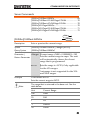
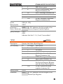
How to Use the Function Menu
Background
The function menu allows you to view the
software information, set the remote settings,
the DCV, ACV, DCA, ACA averaging settings
and other settings.
Menu Item
Range/Description
Software Version Displays the software version
on the display.
Factory Default
Load the default settings.
USB to Serial
Port Baud Rate
115200, 57600, 38400, 19200,
9600, 4800
GPIB Address
00 ~ 30
AD Speed
(measurement
resolution)
7_sec (6½ digits), 30_sec (5½
digits), 100_sec (4½ digits)
AVG Mode
SHIFT, TOTAL
DCV AVG
01 ~ 10, 20, 30, 40, 50, 60, 70,
80, 90, 100
ACV AVG
01 ~ 10, 20, 30, 40, 50, 60, 70,
80, 90, 100
DCA AVG
01 ~ 10, 20, 30, 40, 50, 60, 70,
80, 90, 100
ACA AVG
01 ~ 10, 20, 30, 40, 50, 60, 70,
80, 90, 100
Auto Zero
Enable, Disable
Beeper
On, Off
Save Func Set
Saves the settings in the
function menus.
Exit Func Set
Exits the function menu.
31
PCS-1000 User Manual
Steps
1. Press and long push the Func key.
Local
Func
The software version will be
displayed first.
CURRENT
RMT
ACA
DCA 300A
VOLTAGE
30A
Auto
ERROR
ACV
DCV
mV
A
V
2. Use the ◄ Func ► keys to
scroll through the menu
items.
3. Use the ▼Select ▲ keys to
choose the parameter for
the selected menu item.
Local
AC / DC
Func
Func
300A / 30A
3A Range
Auto
Select
4. Press the Enter key to set the
parameter and go to the next
menu item.
Save Setup
Auto
mA
Range
Auto
Enter
To save the settings use the ◄ Func ► keys to
navigate to SAVE FUNC SET.
Press the Enter key to save all the settings and
exit the function menu.
Exit Without
Saving
To exit without saving, navigate to the EXIT
FUNC SET menu using the ◄ Func ► keys and
press the Enter key to exit without saving any
settings.
CURRENT
RMT
Note
32
ACA
DCA 300A
VOLTAGE
30A
Auto
ERROR
ACV
DCV
Auto
mA
mV
A
V
If the settings in the function menu are not saved,
then the settings will only apply until the unit is
reset.
OPERATION
Note
The display uses a 7 segment LED display. The
appendix has an ASCII Table if you have trouble
understanding the characters on the LED display
character set. See page 88.
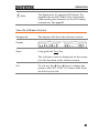
View the Software Version
Background
Display
Steps
The display will show the software version.
CURRENT
RMT
ACA
DCA 300A
VOLTAGE
30A
Auto
ERROR
ACV
DCV
Auto
mA
mV
A
V
Long push the Func key.
The software version is displayed on the screen
(it is the first item in the function menu).
Exit
To exit, use the ◄ Func ► keys to change the
menu to the EXIT FUNC SET menu item. Press
the Enter key to exit.
33
PCS-1000 User Manual
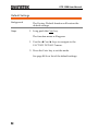
Default Settings
Background
Steps
The Factory Default function will restore the
default settings.
1. Long push the Func key.
The function menu will appear.
1. Use the ◄ Func ► keys to navigate to the
FACTORY DEFAULT menu.
2. Press the Enter key to set the mode.
See page 88 for a list of the default settings.
34
OPERATION
Setting the USB-UART Baud Rate
Background
The baud rate settings are used for remote
control via the USB B port. The USB B
connection uses a virtual COM port to simulate
a serial port (UART) connection. The baud rate
can be set to 115200, 57600, 38400, 19200, 9600,
4800.
See the Communication Interface chapter on
page 42 chapter for details on remote control.
Note
Steps
The USB driver needs to be installed for the
baud rate settings to be applicable. See page 48
for details.
1. Long push the Func key.
The function menu will appear.
2. Use the ◄ Func ► keys to navigate to the
BAUDRATE settings.
3. Use the ▼Select ▲ keys to select a baud rate.
Press the Enter key to set the baud rate.
4. Use the ◄ Func ► keys to change the menu to
the SAVE FUNC SET menu item. Press the
Enter key to save.
Note
To exit without saving, navigate to the EXIT FUNC
SET menu using the ◄ Func ► keys and press the
Enter key to exit without saving any settings.
35
PCS-1000 User Manual
Setting the GPIB Address
Background
The GPIB port is used for remote control. The
GPIB address can be set between 00 ~ 30.
See the Communication Interface chapter on
page 42 chapter for details on remote control.
Steps
1. Long push the Func key.
The function menu will appear.
2. Use the ◄ Func ► keys to navigate to the
ADDRESS settings.
3. Use the ▼Select ▲ keys to select the GPIB
address. Press the Enter key to set the address.
4. Use the ◄ Func ► keys to navigate to the
SAVE FUNC SET menu item. Press the Enter
key to save.
Note
36
To exit without saving, navigate to the EXIT FUNC
SET menu using the ◄ Func ► keys and press the
Enter key to exit without saving any settings.
OPERATION
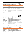
Setting the AD Speed
Background
The ADC IC speed has a number of settings.
The higher the setting, the lower the accuracy
and resolution of the meter.
Range:
Steps
Seconds (resolution):
7 (6½ digits), 30 (5½ digits),
100 (4½ digits)
1. Long push the Func key.
The function menu will appear.
2. Use the ◄ Func ► keys to navigate to the AD
SPEED menu.
3. Use the ▼Select ▲ keys to select the AD speed.
Press the Enter key to set the speed.
By default the AD Speed is set to 7 (6½ digits).
4. Use the ◄ Func ► keys to navigate to the
SAVE FUNC SET menu item. Press the Enter
key to save.
Note
To exit without saving, navigate to the EXIT FUNC
SET menu using the ◄ Func ► keys and press the
Enter key to exit without saving any settings.
37
PCS-1000 User Manual
Setting the Averaging Mode
Background
There are two different types of averaging
modes, SHIFT or TOTAL.
SHIFT is a box car averaging mode while
TOTAL will average all the collected samples
to get the average value.
Range
Steps
SHIFT, TOTAL
1. Long push the Func key.
The function menu will appear.
2. Use the ◄ Func ► keys to navigate to the AVG
MODE menu.
3. Use the ▼Select ▲ keys to select the Averaging
Mode. Press the Enter key to set the mode.
By default the average mode is set to SHIFT.
4. Use the ◄ Func ► keys to navigate to the
SAVE FUNC SET menu item. Press the Enter
key to save.
Note
38
To exit without saving, navigate to the EXIT FUNC
SET menu using the ◄ Func ► keys and press the
Enter key to exit without saving any settings.
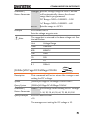
OPERATION
Setting the Averaging Number for the DCV/ACV/DCA/ACA
Background
Each of the different measurement modes
(DCV, ACV, DCA, ACA) can have the number
of averages set individually.
Range
Steps
01 ~ 10, 20, 30, 40, 50, 60, 70, 80, 90,
100
1. Long push the Func key.
The function menu will appear.
2. Use the ◄ Func ► keys to navigate to the DCV
AVG, ACV AVG, DCA AVG or ACA AVG
menu.
3. Use the ▼Select ▲ keys to select the number of
averages for the selected mode. Press the Enter
key to set the mode.
By default the number of averages is 10.
4. Use the ◄ Func ► keys to navigate to the
SAVE FUNC SET menu item. Press the Enter
key to save.
Note
To exit without saving, navigate to the EXIT FUNC
SET menu using the ◄ Func ► keys and press the
Enter key to exit without saving any settings.
39
PCS-1000 User Manual
Setting the Autozero Function
Background
The Autozero function will automatically
perform a zero calibration when the unit is
turned on.
Range
Steps
Enable, Disable
1. Long push the Func key.
The function menu will appear.
2. Use the ◄ Func ► keys to navigate to the
AUTOZERO menu.
3. Use the ▼Select ▲ keys to enable autozero.
Press the Enter key to set the mode.
By default the Autozero is already enabled.
4. Use the ◄ Func ► keys to navigate to the
SAVE FUNC SET menu item. Press the Enter
key to save.
Note
40
To exit without saving, navigate to the EXIT FUNC
SET menu using the ◄ Func ► keys and press the
Enter key to exit without saving any settings.
OPERATION
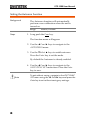
Beeper Settings
Background
The beeper sound that is used for key presses
and other system sounds can be turned on or
off using this menu.
Range
Steps
On, Off
1. Long push the Func key.
The function menu will appear.
2. Use the ◄ Func ► keys to navigate to the
BEEPER menu.
3. Use the ▼Select ▲ keys to the beeper on or off.
Press the Enter key to set the mode.
By default the beeper sound is turned on.
4. Use the ◄ Func ► keys to navigate to the
SAVE FUNC SET menu item. Press the Enter
key to save.
Note
To exit without saving, navigate to the EXIT FUNC
SET menu using the ◄ Func ► keys and press the
Enter key to exit without saving any settings.
41
PCS-1000 User Manual
COMMUNICATION
INTERFACE
This chapter describes basic configuration of
IEEE488.2 based remote control.
Interface Configuration ................................................... 44
Configure GPIB Interface ...........................................................................44
GPIB Function Check .................................................................................45
USB Driver Installation...............................................................................48
USB Interface Settings ...............................................................................50
USB Function Check...................................................................................53
Return to Local Operation..........................................................................55
Command Syntax ............................................................ 56
Command List ................................................................. 59
Configure Commands ................................................................................61
CONFigure..................................................................................................61
CONFigure:CURRent .................................................................................62
CONFigure:CURRent[:DC] .........................................................................62
CONFigure:CURRent:AC ............................................................................63
CONFigure:VOLTage .................................................................................63
CONFigure:VOLTage[:DC] .........................................................................64
CONFigure:VOLTage:AC............................................................................65
CONFigure:AVERage:MODE .....................................................................65
Measure Commands ..................................................................................66
MEASure .....................................................................................................66
MEASure:CURRent[:DC] .............................................................................66
MEASure:CURRent:AC ...............................................................................67
MEASure:VOLTage[:DC].............................................................................67
MEASure:VOLTage:AC ...............................................................................67
READ ...........................................................................................................67
42
COMMUNICATION INTERFACE
Sense Commands...................................................................................... 69
[SENSe:]CURRent:RANGe ......................................................................... 69
[SENSe:]CURRent:DC:AVERage:COUNt ................................................... 70
[SENSe:]CURRent:AC:AVERage:COUNt ................................................... 70
[SENSe:]VOLTage:RANGe ......................................................................... 70
[SENSe:]VOLTage:DC:AVERage:COUNt................................................... 71
[SENSe:]VOLTage:AC:AVERage:COUNt ................................................... 72
System Commands ................................................................................... 73
SYSTem:BEEPer:STATe ............................................................................. 73
SYSTem:ERRor........................................................................................... 74
SYSTem:LOCal........................................................................................... 74
SYSTem:REMote........................................................................................ 75
SYSTem:RWLock ....................................................................................... 75
SYSTem:VERSion....................................................................................... 75
SYSTem:OUTPut:FORMat ........................................................................ 75
Status Commands ..................................................................................... 77
STATus:OPERation:CONDition ................................................................ 77
STATus:OPERation:ENABle ...................................................................... 78
STATus:OPERation[:EVENt] ...................................................................... 78
STATus:PRESet .......................................................................................... 79
STATus:QUEStionable:CONDition ........................................................... 79
STATus:QUEStionable:ENABle ................................................................. 80
STATus:QUEStionable[:EVENt] ................................................................. 80
Common Commands ................................................................................ 81
*IDN? ......................................................................................................... 81
*ESE ........................................................................................................... 81
*ESR? ......................................................................................................... 82
*SRE ........................................................................................................... 82
*STB? ......................................................................................................... 83
*PSC ........................................................................................................... 84
*OPC .......................................................................................................... 84
*TST? ......................................................................................................... 85
*CLS ........................................................................................................... 85
*RST ........................................................................................................... 85
*WAI........................................................................................................... 85
Status Registers .............................................................. 86
Error Messages ............................................................... 87
43
PCS-1000 User Manual
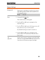
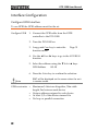
Interface Configuration
Configure GPIB Interface
To use GPIB the GPIB address must first be set.
Configure GPIB
1. Connect the GPIB cable from the GPIB
controller to the PCS-1000.
2. Turn the PCS-1000 on.
3. Long push Func key to enter the
function menu.
Page 31
4. Use the ◄ Func ► keys to go to the ADDRESS
function.
5. Select the address using the ▼Select ▲ keys.
GPIB Address
00~30
6. Press the Enter key to confirm the selection.
RMT will be displayed on the screen when the unit
is remote mode.
Note
GPIB constraints
44
Maximum 14 devices altogether, 20m cable
length, 2m between each device
Unique address assigned to each device
At least 2/3 of the devices turned On
No loop or parallel connection
COMMUNICATION INTERFACE
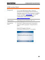
GPIB Function Check
Background
To test the GPIB functionality, National
Instruments Measurement and Automation
Explorer can be used. This program is available
on the NI website, www.ni.com, via a search
for the VISA Run-time Engine page, or
“downloads” at the following URL,
http://www.ni.com/visa/
Requirements
Operating System: Windows XP, 7, 8
Functionality
check
1. Start the NI Measurement and Automation
Explorer (MAX) program. Using Windows,
press:
Start>All Programs>National
Instruments>Measurement & Automation
45
PCS-1000 User Manual
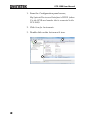
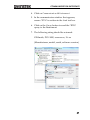
1. From the Configuration panel access;
My System>Devices and Interfaces>GPIBX (where
X is the GPIB card number that is connected to the
PCS-1000).
2. Click Scan for Instruments.
3. Double click on the Instrument 0 icon.
2
1
3
46
COMMUNICATION INTERFACE
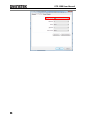
4. Click on Communicate with Instrument.
5. In the communicator window that appears,
ensure *IDN? is written in the Send test box.
6. Click on the Query button to send the *IDN?
query to the instrument.
7. The following string should be returned:
GWInstek, PCS-1000, xxxxxxxxx, Vx.xx
(Manufacturer, model, serial, software version)
4
5
6
7
209.1711 mm.
47
PCS-1000 User Manual
USB Driver Installation
Background
The USB driver is actually a virtual COM port
driver that simulates a serial port (UART)
connection.
Note: The USB driver should not need to be
manually installed if your operating system has
been fully updated. In most cases, the PCS-1000
driver should be automatically installed when
connected to the PC.
If the driver is not automatically detected, or if
your operating system is not fully updated, it
may be necessary to install the USB driver, as
shown below.
Requirements
Operating System: Windows XP, Vista, 7, 8, 8.1
Note
The following installation instructions only apply if
the USB driver does not get automatically installed.
Steps
1. Connect the PCS-1000 to a PC using the USB
Type A-Type B cable (GTL-240).
2. The Windows Found New Hardware wizard
should pop up asking you to install the device
driver.
3. Select Locate and install driver software.
4. You will now be asked to insert a disk that
contains the USB driver.
Insert the User Manual CD. Windows will
automatically install the USB driver.
Note: If the Windows Security pop-up appears,
48
COMMUNICATION INTERFACE
choose Install this driver software anyway.
5. The PCS-1000 will now become available in the
device tree under PORTS (COM & LPT) in the
Windows Device Manager.
Alternate
Installation
If the Found New Hardware wizard does not
appear or you wish to install the driver from
another location, the driver can be also installed
from the Windows Device Manager.
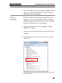
1. Open the Windows Device Manager. Using
Windows 7, press:
Start>Control Panel>Hardware and Sound>Device
Manager
2. From the device tree go to: Other devices>USB
Serial Port
The yellow error sign indicates that a driver has not
been installed.
49
PCS-1000 User Manual
3. Right-click USB Serial Port and select Update
Driver Software.
Select Browse my computer for driver software
when prompted.
Select the directory with the USB drivers from
the User Manual CD when prompted.
Note: If the Windows Security pop-up appears,
choose Install this driver software anyway.
4. The PCS-1000 will now become available in the
device tree under PORTS (COM & LPT).
Note
If required, the USB drivers can be downloaded
from http://www.ftdichip.com/Drivers/VCP.htm.
If the drivers are downloaded, they can be installed
using the Alternate Installation method described
on the previous page.
USB Interface Settings
Baud Rate
Settings
1. Connect the USB cable from the PC to the rear
panel USB-B port on the PCS-1000.
2. Turn the PCS-1000 on.
3. Long push Func key to enter the
function menu.
Page 31
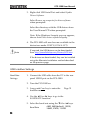
4. Use the ◄ Func ► keys to go to the
BAUDRATE function.
5. Select the baud rate using the ▼Select ▲ keys.
4800, 9600(default), 19200,
Baud Rate
38400, 57600, 115200
50
COMMUNICATION INTERFACE
6. Press the Enter key to confirm the selection.
7. Use the ◄ Func ► keys to go to the SAVE
FUNC SET function.
8. Press the Enter key to save the baud rate
settings.
Edit UART
Settings
1. Connect the PCS-1000 to the PC using the GTL240 USB cable.
2. Open the Windows Device Manager, using
Windows 7, click:
Start>Control Panel>Hardware and Sound>Device
Manager:
3. In the device tree go to: PORTS (COM &
LPT)>PCS-1000 (COM XX)
4. Right-click PCS-1000 and select Properties.
5. Go to the Port Settings tab and from there you
can set any other UART settings such as data
bits, parity, number of stop bits and the flow
control.
51
PCS-1000 User Manual
52
COMMUNICATION INTERFACE
USB Function Check
Background
To test the USB functionality, National
Instruments Measurement and Automation
Explorer can be used. This program is available
on the NI website, www.ni.com, via a search
for the VISA Run-time Engine page, or
“downloads” at the following URL,
http://www.ni.com/visa/
Requirements
Operating System: Windows XP, 7, 8, 8.1
Functionality
check
1. Open the Windows Device Manager to see
which COM port the PCS has been assigned.
Using Windows 7, press:
Start>Control Panel>Hardware and Sound>Device
Manager
The COM port number will be shown in the
device tree under: PORTS (COM & LPT)>PCS1000 (COM XX)
2. Start the NI Measurement and Automation
Explorer (MAX) program. Using Windows,
press:
Start>All Programs>National
Instruments>Measurement & Automation
53
PCS-1000 User Manual
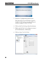
3. From the Configuration panel access;
My System>Devices and Interfaces>Serial &
Parallel>COMX (where X is the COM port
number assigned to the PCS-1000).
4. Click on the Port Settings tab at the bottom.
5. Make sure the Baud rate settings are correct
(PCS-1000 default = 9600 baud).
6. Click on Open Visa Test Panel.
6
3
5
4
54
COMMUNICATION INTERFACE
7. Click on Input/Output.
8. In the Select or Enter Command drop down list,
ensure *IDN?\n is selected.
9. Click on the Query button to send the *IDN?
query to the instrument.
10. The following string should be returned:
GWInstek, PCS-1000, xxxxxxxxx, Vx.xx
(Manufacturer, model, serial, software version)
7
8
9
10
Return to Local Operation
Steps
1. Press the Local key to return to local operation.
2. The RMT icon will turn off when you have
returned to local mode.
55
PCS-1000 User Manual
Command Syntax
Compatible
Standard
Command
Structure
IEEE488.2
Partial compatibility
SCPI, 1999
Partial compatibility
SCPI commands follow a tree-like structure,
organized into nodes. Each level of the
command tree is a node. Each keyword in a
SCPI command represents each node in the
command tree. Each keyword (node) of a SCPI
command is separated by a colon (:).
For example, the diagram below shows an SCPI
sub-structure and a command example.
MEASure
MEASure:CURRent:DC?
CURRent
DC
Command types
AC
There are a number of different instrument
commands and queries. A command sends
instructions or data to the unit and a query
receives data or status information from the
unit.
Command types
56
Simple
A single command
with/without a parameter
Example
*IDN?
COMMUNICATION INTERFACE
Query
A query is a simple or
compound command
followed by a question mark
(?). A parameter (data) is
returned.
Example
meas:curr:dc?
Compound
Two or more commands on
the same command line.
Compound commands are
separated with either a semicolon (;) or a semi-colon and a
colon (;:).
A semi-colon is used to join
two related commands, with
the caveat that the last
command must begin at the
last node of the first
command.
A semi-colon and colon are
used to combine two
commands from different
nodes.
Example
conf:curr?;:meas:volt:dc?
57
PCS-1000 User Manual
Command Forms
Commands and queries have two different
forms, long and short. The command syntax is
written with the short form of the command in
capitals and the remainder (long form) in lower
case.
The commands can be written in capitals or
lower-case, just so long as the short or long
forms are complete. An incomplete command
will not be recognized.
Below are examples of correctly written
commands.
Long
CONFigure:VOLTage?
form
CONFIGURE:VOLTAGE?
configure:voltage?
Short
CONF:VOLT?
form
conf:volt?
Square Brackets
Commands that contain square brackets
indicate that the contents are optional. The
function of the command is the same with or
without the square bracketed items, as shown
below.
For “MEASure:CURRent[:DC]?”, both
“MEASure:CURRent:DC?” and
“MEASure:CURRent?” are both valid forms.
Command
Format
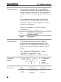
CURR:RANG
1
Parameters
58
2
AUTO
1.
3
2.
3.
Command
header
Space
Parameter 1
Type
<Boolean>
Description
Example
Boolean logic
0, 1
<NR1>
integers
0, 1, 2, 3
COMMUNICATION INTERFACE
<NR2>
decimal
numbers
0.1, 3.14, 8.5
<NR3>
floating point
4.5e-1, 8.25e+1
<NRf>
any of NR1, 2, 3 1, 1.5, 4.5e-1
<block data> Definitive length arbitrary block
data. A single decimal digit
followed by data. The decimal
digit specifies how many 8-bit
data bytes follow.
Message
Terminator
LF
Line feed code
Command List
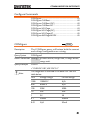
Configure
Commands
Measure
Commands
Sense
Commands
CONFigure .................................................................. 61
CONFigure:CURRent .................................................. 62
CONFigure:CURRent[:DC] ......................................... 62
CONFigure:CURRent:AC ............................................ 63
CONFigure:VOLTage.................................................. 63
CONFigure:VOLTage[:DC] ......................................... 64
CONFigure:VOLTage:AC ............................................ 65
CONFigure:AVERage:MODE ..................................... 65
MEASure ..................................................................... 66
MEASure:CURRent[:DC] ............................................. 66
MEASure:CURRent:AC ............................................... 67
MEASure:VOLTage[:DC] ............................................. 67
MEASure:VOLTage:AC ............................................... 67
READ ........................................................................... 67
[SENSe:]CURRent:RANGe .......................................... 69
[SENSe:]CURRent:DC:AVERage:COUNt .................... 70
[SENSe:]CURRent:AC:AVERage:COUNt .................... 70
[SENSe:]VOLTage:RANGe .......................................... 70
[SENSe:]VOLTage:DC:AVERage:COUNt.................... 71
[SENSe:]VOLTage:AC:AVERage:COUNt .................... 72
59
PCS-1000 User Manual
System
Commands
SYSTem:BEEPer:STATe ...............................................73
SYSTem:ERRor ............................................................74
SYSTem:LOCal ............................................................74
SYSTem:REMote..........................................................75
SYSTem:RWLock .........................................................75
SYSTem:VERSion.........................................................75
SYSTem:OUTPut:FORMat ..........................................75
Status
Commands
STATus:OPERation:CONDition ..................................77
STATus:OPERation:ENABle ........................................78
STATus:OPERation[:EVENt] ........................................78
STATus:PRESet ............................................................79
STATus:QUEStionable:CONDition .............................79
STATus:QUEStionable:ENABle ...................................80
STATus:QUEStionable[:EVENt]...................................80
Common
Commands
*IDN? ...........................................................................81
*ESE .............................................................................81
*ESR? ...........................................................................82
*SRE .............................................................................82
*STB? ...........................................................................83
*PSC .............................................................................84
*OPC ............................................................................84
*TST? ...........................................................................85
*CLS .............................................................................85
*RST .............................................................................85
*WAI.............................................................................85
60
COMMUNICATION INTERFACE
Configure Commands
CONFigure .................................................................. 61
CONFigure:CURRent .................................................. 62
CONFigure:CURRent[:DC] ......................................... 62
CONFigure:CURRent:AC ............................................ 63
CONFigure:VOLTage.................................................. 63
CONFigure:VOLTage[:DC] ......................................... 64
CONFigure:VOLTage:AC ............................................ 65
CONFigure:AVERage:MODE ..................................... 65
CONFigure
Query
Description
The CONFigure query will return both the current
and voltage configuration as a string.
Query Syntax
CONFigure?
Return Parameter <string> Current mode, range unit, voltage mode,
range unit.
Query Example
CONF?
>”CURR:DC 0.01,VOLT:DC 0.1”
Note
The range that is returned is the base unit. See the
table below:
Unit
Voltage Range
Current Range
1000
1000VDC
N/A
600
600ACV
N/A
100
200V
300A
10
20V
30A
1
2V
3A
0.1
200mV
300mA
0.01
N/A
30mA
61
PCS-1000 User Manual
CONFigure:CURRent
Query
Description
The CONFigure:CURRent query will return the
current range unit.
Query Syntax
CONFigure:CURRent?
Return Parameter <string> Returns the current mode and range unit.
Query Example
CONF:CURR?
> “DC 0.01”
Note
The range that is returned is the base unit. See the
table below:
Unit
Current Range
100
300A
10
30A
1
3A
0.1
300mA
0.01
30mA
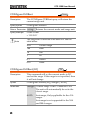
CONFigure:CURRent[:DC]
Set
Description
This command will set the current mode to DC
and set the range. If the range is not specified, then
it will not change.
Syntax
CONFigure:CURRent[:DC] [<Range> | AUTO]
Parameter
<Range> Current range <NRf>: 0.00000001~305
The unit will automatically be set to the
closest range.
AUTO
Autorange; Only applicable for the ≤3A
ranges.
Autorange is not supported for the 30A
and 300A ranges.
62
COMMUNICATION INTERFACE
Example
CONF:CURR 20
Sets the current mode to DC and the range to 30A
Example
CONF:CURR
Sets the current mode to DC. The range is not
changed.
CONFigure:CURRent:AC
Set
Description
This command will set current mode to AC and set
the range. If the range is not specified, then it will
not change.
Syntax
CONFigure:CURRent:AC [<Range> | AUTO]
Parameter
<Range> Current range <NRf>: 0.00000001~305
Current range. The unit will
automatically be set to the closest range.
AUTO
Autorange; Only applicable for the ≤3A
ranges.
Autorange is not supported for the 30A
and 300A ranges.
Example
CONF:CURR:AC 100
Sets the current mode to AC and the range to 300A.
Example
CONF:CURR:AC
Sets the current mode to AC. The range is not
changed.
CONFigure:VOLTage
Query
Description
The CONFigure:VOLTage query will return the
voltage mode and the voltage range unit.
Query Syntax
CONFigure:VOLTage?
Return Parameter <string> Returns the voltage mode and range unit.
63
PCS-1000 User Manual
Query Example
CONF:VOLT?
>”DC 0.1”
The mode is DCV and the range is 200mV.
Note
The range that is returned is the base voltage unit. See
the table below:
Unit
Voltage Range
1000
1000VDC
600
600ACV
100
200V
10
20V
1
2V
0.1
200mV
CONFigure:VOLTage[:DC]
Set
Description
This command will set the voltage mode to DC
and set the DCV range. If the range is not specified
then it will not be changed.
Syntax
CONFigure:VOLTage[:DC] [<Range> | AUTO]
Parameter
<Range> Voltage range <NRf>: 0.0000001 ~ 1050
The unit will automatically be set to the
closest range.
AUTO
Example
Autoset
CONF:VOLT:DC 20
Sets the voltage mode to DC and the DCV range to
20V.
Example
CONF:VOLT:DC
Sets the voltage mode to DC. The range stays the
same.
64
COMMUNICATION INTERFACE
CONFigure:VOLTage:AC
Set
Description
This command will set the voltage mode to AC
and set the ACV range. If the range is not specified
then it will not be changed.
Syntax
CONFigure:VOLTage:AC [<Range> | AUTO]
Parameter
<Range> Voltage range <NRf>: 0.0000001~630
The unit will automatically be set to the
closest range.
AUTO
Example
Autoset
CONF:VOLT:AC 20
Sets the voltage mode to AC and the ACV range to
20V.
Example
CONF:VOLT:AC
Sets the voltage mode to AC. The range stays the
same.
Set
CONFigure:AVERage:MODE
Query
Description
This command will set or query the average mode.
Syntax
CONFigure:AVERage:MODE {0|1,TOTAL|SHIFT}
Query Syntax
CONFigure:AVERage:MODE?
Parameter
0, TOTAL Total mode
1, SHIFT Shift mode
Return Parameter Total
Total mode
Shift
Shift mode
Example
CONF:AVER:MODE 0
Sets the average mode to Total mode.
65
PCS-1000 User Manual
Measure Commands
MEASure ......................................................................66
MEASure:CURRent[:DC] ..............................................66
MEASure:CURRent:AC ................................................67
MEASure:VOLTage[:DC]..............................................67
MEASure:VOLTage:AC ................................................67
READ ............................................................................67
MEASure
Query
Description
This query will return all the measurements.
Query Syntax
MEASure?
Return Parameter <NRf>
Returns the current measurement voltage
measurement:
<current>,<voltage>
Query Example
MEAS?
> 9.9768E-1, 3.21E-1
Returns the current measurement (0.99A) and voltage
(0.321V) measurement.
MEASure:CURRent[:DC]
Query
Description
This query will return the DC current.
Query Syntax
Measure:CURRent[:DC]?
Return Parameter <NRf>
Query Example
Return the DC current.
MEAS:CURR:DC?
>+9.9067E-1
Returns DC current measurement (0.99A).
66
COMMUNICATION INTERFACE
MEASure:CURRent:AC
Query
Description
This query will return the AC current.
Query Syntax
MEASure:CURRent:AC?
Return Parameter <NRf>
Query Example
Returns the AC current.
MEAS:CURR:AC?
>+9.9067E-1
Returns the AC current measurement (0.9A).
MEASure:VOLTage[:DC]
Query
Description
This query will return the DC voltage.
Query Syntax
MEASure:VOLTage[:DC]?
Return Parameter <NRf>
Query Example
Returns the DC voltage
MEAS:VOLT:DC?
>+1.5E+1
Returns the DC voltage measurement (15.0 V).
MEASure:VOLTage:AC
Query
Description
This query will return the AC voltage.
Query Syntax
MEASure:VOLTage:AC?
Return Parameter <NRf>
Query Example
Returns the AC voltage.
MEAS:VOLT:AC?
>+2.5E+1
Returns the AC voltage measurement (25V).
READ
Description
Query
The read command will return current and voltage
reading.
67
PCS-1000 User Manual
Query Syntax
READ?
Return Parameter <NRf>
Query Example
Returns the current and voltage readings,
respectively
<current>,<voltage>
READ?
> +9.9067E-1,+2.5E+1
Returns the current and voltage readings.
68
COMMUNICATION INTERFACE
Sense Commands
[SENSe:]CURRent:RANGe .......................................... 69
[SENSe:]CURRent:DC:AVERage:COUNt .................... 70
[SENSe:]CURRent:AC:AVERage:COUNt .................... 70
[SENSe:]VOLTage:RANGe .......................................... 70
[SENSe:]VOLTage:DC:AVERage:COUNt.................... 71
[SENSe:]VOLTage:AC:AVERage:COUNt .................... 72
Set
[SENSe:]CURRent:RANGe
Query
Description
Sets or queries the current range.
Syntax
[SENSe:]CURRent:RANGe {<Range>|AUTO}
Query Syntax
[SENSe:]CURRent:RANGe?
<Range> Current range <NRf>: 0.00000001~305
Sets the current range in amps. The unit
Return Parameter
will automatically choose the closest
range that is programmed.
Parameter /
AUTO
Sets the range to AUTO; Only applicable
for the ≤3A ranges.
Autorange is not supported for the 30A
and 300A ranges.
Example
CURR:RANG AUTO
Sets the current range to AUTO.
Note
The range that is returned is the base unit. See the
table below:
Unit
Current Range
100
300A
10
30A
1
3A
.1
300mA
.01
30mA
69
PCS-1000 User Manual
Set
[SENSe:]CURRent:DC:AVERage:COUNt
Query
Description
This query will set or return average count setting
for DC current.
Syntax
[SENSe:]CURRent:DC:AVERage:COUNt (NR1)
Query Syntax
[SENSe:]CURRent:DC:AVERage:COUNt?
Parameter /
<NR1>
1~10, 20, 30, 40, 50, 60, 70, 80, 90, 100
Return Parameter
Query Example
The average count setting for DC current.
CURR:DC:AVER:COUN?
>10
The average count setting for DC current is 10.
Set
[SENSe:]CURRent:AC:AVERage:COUNt
Query
Description
This query will set or return average count setting
for AC current.
Syntax
[SENSe:]CURRent:AC:AVERage:COUNt (NR1)
Query Syntax
[SENSe:]CURRent:AC:AVERage:COUNt?
Return Parameter <NR1>
The average count setting for AC current.
1~10, 20, 30, 40, 50, 60, 70, 80, 90, 100
Query Example
CURR:AC:AVER:COUN?
>10
The average count setting for AC current is 10.
Set
[SENSe:]VOLTage:RANGe
Query
Description
Sets or queries the voltage range.
Syntax
[SENSe:]VOLTage:RANGe {<Range>|AUTO}
Query Syntax
[SENSe:]VOLTage:RANGe?
70
COMMUNICATION INTERFACE
<Range> Sets the voltage range in volts. The unit
will automatically choose the closest
Return Parameter
range that is programmed.
Parameter /
DC Range <NRf>: 0.0000001 ~ 1050
AC Range <NRf>: 0.0000001 ~ 600
AUTO
Example
Sets the range to AUTO.
VOLT:RANG AUTO
Sets the voltage range to auto.
Note
The range that is returned is the base voltage unit. See
the table below:
Unit
Voltage Range
1000
1000VDC
600
600ACV
100
200V
10
20V
1
2V
0.1
200mV
Set
[SENSe:]VOLTage:DC:AVERage:COUNt
Query
Description
This command will set or return the average count
setting for DC voltage.
Syntax
[SENSe:]VOLTage:DC:AVERage:COUNt <NR1>
Query Syntax
[SENSe:]VOLTage:DC:AVERage:COUNt?
Parameter /
<NR1>
1~10, 20, 30, 40, 50, 60, 70, 80, 90, 100
Return Parameter
Query Example
The average count setting for DC voltage.
VOLT:DC:AVER:COUN?
>10
The average count setting for DC voltage is 10.
71
PCS-1000 User Manual
Set
[SENSe:]VOLTage:AC:AVERage:COUNt
Query
Description
This query will set or return the average count
setting for AC current.
Syntax
[SENSe:]VOLTage:AC:AVERage:COUNt <NR1>
Query Syntax
[SENSe:]VOLTage:AC:AVERage:COUNt?
Return Parameter <NR1>
The average count setting for AC voltage.
1~10, 20, 30, 40, 50, 60, 70, 80, 90, 100
Query Example
VOLT:AC:AVER:COUN?
>10
The average count setting for AC voltage is 10.
72
COMMUNICATION INTERFACE
System Commands
SYSTem:BEEPer:STATe .............................................. 73
SYSTem:ERRor............................................................ 74
SYSTem:LOCal............................................................ 74
SYSTem:REMote......................................................... 75
SYSTem:RWLock ........................................................ 75
SYSTem:VERSion........................................................ 75
SYSTem:OUTPut:FORMat ......................................... 75
Set
SYSTem:BEEPer:STATe
Query
Description
Sets or queries the beeper status.
Syntax
SYSTem:BEEPer:STATe {0|1}
Query Syntax
SYSTem:BEEPer:STATe?
Parameter/
1
Return Parameter
0
Query Example
Beeper on
Beeper off
SYST:BEEP:STAT?
>1
The beeper is on.
73
PCS-1000 User Manual
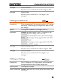
SYSTem:ERRor
Description
Query
Queries the error queue. Error messages are stored
in FIFO order. Up to 20 error messages are stored
in the error queue. The first error message that is
stored is the first message that is returned. Each
time a message is returned it is also cleared from
the queue. When the error queue is queried and
there are no error messages, 0, "No error" will be
returned. If the error queue is full (20 messages)
and an error occurs, the last-stored error message
will be overwritten with the
-350,"Error queue overflow" message. This
message will remain, and no additional messages
will be stored until it is cleared.
See page 87 for a list of the error messages.
Query Syntax
SYSTem:ERRor?
Return Parameter <string> Returns the next error message in the
error queue.
Query Example
SYST:ERR?
> 0, "No error."
Returns no error in the error queue.
SYSTem:LOCal
Set
Description
Returns the unit back to local mode. This
command will enable all panel keys that may have
been locked.
Syntax
SYSTem:LOCal
74
COMMUNICATION INTERFACE
SYSTem:REMote
Set
Description
Sets the PCS-1000 operation to remote mode. All
panel keys except the Local key are locked.
Syntax
SYSTem:REMote
SYSTem:RWLock
Set
Description
Sets the PCS-1000 operation to remote mode. All
panel keys are locked, including the Local key.
Syntax
SYSTem:RWLock
SYSTem:VERSion
Query
Description
Queries the SCPI version number.
Query Syntax
SYSTem:VERSion?
Return Parameter <string> Returns the SCPI version as a string.
Query Example
SYST:VERS?
>1999.0
Returns the SCPI version number as 1999.0.
Set
SYSTem:OUTPut:FORMat
Description
Query
Sets or queries the output formatting. There are 4
types of output formatting: 0, 1, 2, 3.
Format “0” is the default format.
The following table will show how each format
will differ from each other when the MEASure?
query is used.
Format Description
0
Example
Returns the output in +0.0E+0,-4.0E-7
NR3 format.
75
PCS-1000 User Manual
1
Returns the output in +0.0E+0 ADC,-5.0ENR3 format + unit.
7 VDC
2
Returns the output in +0.00000000,NR2 format.
0.0000004
3
Returns the output in +0.00000000 ADC,NR2 format + unit.
0.0000004 VDC
Syntax
SYSTem:OUTPut:FORMat (0~3)
Query Syntax
SYSTem:OUTPut:FORMat?
Parameter /
<NR1>
0~3
Return Parameter
Example
SYST:OUTP:FORM?
>3
Returns the format as NR2 + unit.
76
COMMUNICATION INTERFACE
Status Commands
STATus:OPERation:CONDition ................................. 77
STATus:OPERation:ENABle ....................................... 78
STATus:OPERation[:EVENt] ....................................... 78
STATus:PRESet ........................................................... 79
STATus:QUEStionable:CONDition ............................ 79
STATus:QUEStionable:ENABle .................................. 80
STATus:QUEStionable[:EVENt] .................................. 80
STATus:OPERation:CONDition
Description
Query
Returns the contents of the Standard Operation
Condition Register.
Bit
0
1~3
4
5~7
8
9~15
Bit weight
1
~
16
~
256
~
Description
Calibrating
Not used
Measuring
Not used
Config Change
Not used
Query Syntax
STATus:OPERation:CONDition?
Return Parameter <NR1> 0~65535: Returns the bit weight of the
Standard Operation Condition Register.
Query Example
STAT:OPER:COND?
> 256
Indicates that the configuration has been changed.
77
PCS-1000 User Manual
Set
STATus:OPERation:ENABle
Description
Query
Returns or sets the contents of the Standard
Operation Enable Register.
Bit
0
1~3
4
5~7
8
9~15
Bit weight
1
~
16
~
256
~
Description
Calibrating
Not used
Measuring
Not used
Config Change
Not used
Syntax
STATus:OPERation:ENABle (0~65535)
Query Syntax
STATus:OPERation:ENABle?
Parameter /
<NR1>
Return Parameter
Query Example
0~65535: Indicates the bit weight of the
Standard Operation Enable Register.
STAT:OPER:ENAB 273
Enables bit 0, 4 and 8 of the Standard Operation
Enable Register.
STATus:OPERation[:EVENt]
Description
Returns the contents of the Standard Operation
Event Register.
Bit
0
1~3
4
5~7
8
9~15
Query Syntax
Bit weight
1
~
16
~
256
~
Description
Calibrating
Not used
Measuring
Not used
Config Change
Not used
STATus:OPERation[:EVENt]?
Return Parameter <NR1>
78
Query
0~65535: Returns the bit weight of the
Standard Operation Event Register.
COMMUNICATION INTERFACE
Example
SYST:OPER?
>256
Indicates that bit 8 has been latched.
STATus:PRESet
Set
Description
Resets the Standard Event Enable Register, the
Questionable Data Enable Register and the
Standard Operation Enable Register to their
default state.
Syntax
STATus:PRESet
STATus:QUEStionable:CONDition
Description
Returns the contents of the Questionable Data
Condition Register.
Bit
0
1
2~15
Query Syntax
Bit weight
1
2
~
Description
Volt Overload
Current Overload
Not used
STATus:QUEStionable:CONDition?
Return Parameter <NR1>
Query Example
Query
0~65535: Returns the bit weight of the
Questionable Data Condition Register.
STAT:QUES:COND?
>1
Indicates there was a voltage overload.
79
PCS-1000 User Manual
Set
STATus:QUEStionable:ENABle
Description
Query
Returns or sets the contents of the Questionable
Data Enable Register.
Bit
0
1
2~15
Bit weight
1
2
~
Description
Volt Overload
Current Overload
Not used
Syntax
STATus:QUEStionable:ENABle (0~65535)
Query Syntax
STATus:QUEStionable:ENABle?
Parameter /
<NR1>
Return Parameter
Query Example
0~65535: Indicates the bit weight of the
Questionable Data Enable Register.
STAT:QUES:ENAB 3
Enables bit 1and 2 of the Questionable Data Enable
Register.
STATus:QUEStionable[:EVENt]
Description
Returns the contents of the Questionable Data
Event Register.
Bit
0
1
2~15
Query Syntax
Bit weight
1
2
~
Description
Volt Overload
Current Overload
Not used
STATus:QUEStionable[:EVENt]?
Return Parameter <NR1>
Example
Query
0~65535: Returns the bit weight of the
Questionable Data Event Register.
SYST:QUES?
>0
Indicates that no events have been latched.
80
COMMUNICATION INTERFACE
Common Commands
*IDN? .......................................................................... 81
*ESE ............................................................................ 81
*ESR? .......................................................................... 82
*SRE ............................................................................ 82
*STB? .......................................................................... 83
*PSC ............................................................................ 84
*OPC ........................................................................... 84
*TST?........................................................................... 85
*CLS ............................................................................ 85
*RST ............................................................................ 85
*WAI............................................................................ 85
*IDN?
Query
Description
Returns the manufacturer, model number, serial
number and software version number.
Query Syntax
*IDN?
Query Example
*IDN?
>GWInstek,PCS-1000,xxxxxxxxx,Vx.xx
Set
*ESE
Description
Query
Returns or sets the contents of the Standard Event
Enable Register.
Bit
0
1
2
3
4
5
6
7
Bit weight
1
2
4
8
16
32
64
128
Description
Operation Complete
Not used
Query Error
Device Error
Execution Error
Command Error
Not used
Power On
81
PCS-1000 User Manual
Syntax
*ESE (0~255)
Query Syntax
*ESE?
0~255: Indicates the bit weight of the
Standard Event Enable Register.
Parameter /
<NR1>
Return Parameter
Query Example
*ESE 189
Enables all bits except for bit 1 and 6.
*ESR?
Description
Query
Queries the Standard Event Register.
Bit
0
1
2
3
4
5
6
7
Query Syntax
*ESR?
Parameter
<NR1>
Query Example
*ESR?
Bit weight
1
2
4
8
16
32
64
128
Description
Operation Complete
Not used
Query Error
Device Error
Execution Error
Command Error
Not used
Power On
0~255: Indicates the bit weight of the
Standard Event Register.
>32
Indicates a command error was encountered.
Set
*SRE
Description
Query
Returns or sets the contents of the Service Request
Enable Register.
Bit
0
1
82
Bit weight
1
2
Description
Not used
Not used
COMMUNICATION INTERFACE
2
3
4
8
4
5
6
7
16
32
~
128
Syntax
*SRE (0~255)
Query Syntax
*SRE?
Parameter /
<NR1>
Return Parameter
Query Example
ERR: Error queue
QUES: Questionable Data
Register summary bit
MAV: Message available bit
ESB: Event summary bit
~
OPER: Standard Operation
Register summary bit
0~255: Indicates the bit weight of the
Service Request Enable Register.
*SRE?
>188
Indicates that bits 2, 3, 4, 5 and 7 are enabled.
*STB?
Query
Description
Queries the Status Byte Register.
Bit Summary
Bit
0
1
2
3
Bit weight
1
2
4
8
4
5
6
16
32
64
7
128
Query Syntax
*STB?
Parameter
<NR1>
Description
Not used
Not used
ERR: Error queue
QUES: Questionable Data
Register summary bit
MAV: Message available bit
ESB: Event summary bit
MSS: Master summary bit of
the Service Request Register
and the Status Byte Register.
OPER: Operation status
register summary bit
0~255: Indicates the bit weight of the
Status Byte Register.
83
PCS-1000 User Manual
Query Example
*STB?
>4
Indicates that there is a message in the error queue.
Set
*PSC
Query
Description
The Power on Status Clear command enables the
unit to clear the Service Request Enable, the
Standard Event Enable and other event enable
registers at power up.
Syntax
*PSC (0|1)
Query Syntax
*PSC?
Parameter /
0
Return Parameter
1
Query Example
Disabled
Enabled
*PSC 0
Disables the clearing of the event registers at power
up.
Set
*OPC
Query
Description
The Operation Complete command will set bit 0 of
the Standard Event Register when all pending
operations are complete. The OPC? query will
return 1 when all pending operations are complete.
Syntax
*OPC
Query Syntax
*OPC?
Return Parameter 1
Query Example
Enabled
*OPC?
>1
Indicates that all pending operations are complete.
84
COMMUNICATION INTERFACE
*TST?
Query
Description
Self-test query. This query will initiate a self-test
and return the result.
Query Syntax
*TST?
Parameter
0
All tests have passed.
1
One of more tests have failed.
Query Example
*TST?
>0
Indicates that all tests have passed.
*CLS
Set
Description
The Clear Status command will clear the Status
Byte Register by clearing the error queue, and
register groups that connect to the Status Byte
Register with a summary bit.
Syntax
*CLS
*RST
Set
Description
The Reset command will reset the unit to factory
default settings.
Syntax
*RST
*WAI
Set
Description
The Wait command will make the unit wait until
all pending operations are complete.
Syntax
*WAI
85
PCS-1000 User Manual
Status Registers
Questionable Data Register
Condition
Event
Enable
Voltage Overload
0
0
0
Current Overload
1
1
1
Not Used
2
2
2
Not Used
3
3
3
Not Used
4
4
4
Not Used
5
5
5
Not Used
6
6
6
Not Used
7
7
7
Not Used
8
8
8
Not Used
9
9
9
Not Used
10
10
10
Not Used
11
11
11
Not Used
12
12
12
Not Used
13
13
13
Not Used
14
14
14
Not Used
15
15
15
Output
Buffer
:
:
:
Error Que
:
:
:
STAT:QUES:COND?
STAT:QUES:EVEN?
STAT:QUES:ENAB
STAT:QUES:ENAB?
Standard Event Register
Event
Enable
OPC (Operation Complete)
0
0
Not Used
1
1
QUE (Query Error)
2
2
Device Error
3
3
EXE (Execution Error)
4
4
CME (Command Error)
5
5
Not Used
6
6
PON (Power On)
7
7
*ESR?
*ESE
*ESE?
Standard Operation Register
Condition
Event
Enable
Calibrating
0
0
0
Not Used
1
1
1
Not Used
2
2
2
Not Used
3
3
3
Measuring
4
4
4
Not Used
5
5
5
Not Used
6
6
6
Not Used
7
7
7
Config Change
8
8
Not Used
9
9
9
Not Used
10
10
10
Not Used
11
11
11
Not Used
12
12
12
Not Used
13
13
13
Not Used
14
14
14
Not Used
15
15
15
8
STAT:OPER:COND?
STAT:OPER:EVEN?
STAT:OPER:ENAB
STAT:OPER:ENAB?
86
Status
Byte
Register
Service
Request
Enable
Register
0
0
1
1
ERR
2
2
QUES
3
3
MAV
4
4
ESB
5
5
MSS
6
6
OPER
7
7
Serial Poll
*SRE
*STB?
*SRE?
Summary Bit (RQS)
COMMUNICATION INTERFACE
Error Messages
Command Errors 0,"No error"
-101,"Invalid character"
-102,"Syntax error"
-103,"Invalid separator"
-108,"Parameter not allowed"
-109,"Missing parameter"
-113,"Undefined header"
-121,"Invalid character in number"
-123,"Numeric overflow"
-131,"Invalid suffix"
-148,"Character data not allowed"
-151,"Invalid string data"
Execution Errors -222,"Data out of range"
-224,"Illegal parameter value"
Device Specific
Errors
-300,"Device-specific error"
-330,"Self-test failed"
-350,"Error queue overflow"
Query Errors
-410,"Query INTERRUPTED"
-420,"Query UNTERMINATED"
-521,"Input buffer overflow"
-522,"Output buffer overflow"
87
PCS-1000 User Manual
APPENDIX
PCS Default Settings
The following default settings are the factory configuration settings
when the unit first ships. See page 34 to restore the factory default
settings.
Initial Settings
Current Meter
Voltage Meter
Current Range
Voltage Range
Baud rate
GPIB address
AD Speed
AVG Mode
DCV AVG
ACV AVG
DCA AVG
ACA AVG
Autozero
Beeper
Default Setting
DCA
DCV
Auto (Auto range only for 30mA, 300mA, 3A)
Auto
9600
08
7 seconds ( 6½ digits)
Shift
10 (samples)
10 (samples)
10 (samples)
10 (samples)
Enable
On
LED ASCII Table Character Set
Use the following table to read the LED display messages.
0
1
2
3
4
5
6
7
8
9
A
B
C
D
R
E
F
G
H
I
J
K
L
M
N
O
P
Q
S
T
U
V
W
X
Y
Z
(
)
+
-
,
88
APPENDIX
PCS-1000 Specifications
The specifications apply when the PCS is powered on for at least 30
minutes.
General
Power Supply
100 V / 120 V / 220 V / 240 V ±10%
Power Line Frequency 50/60Hz
Operating Environment Full accuracy for 0˚C to 50˚C, Full accuracy to 80% R.H.
at 40˚C
Storage Environment -40˚C to 70˚C
Power Consumption
Max 35VA
Dimensions
210mm (W) * 80mm (H) * 390mm (D)
Weight
Approximately 6 kg
DC Characteristics
DC Voltage
DC Current
1 Year
Temperature
23˚C ± 5˚C
Coefficient/˚C
200.0000 mV
0.0050 + 0.0035
0.0005 + 0.0005
2.000000 V
0.0050 + 0.0010
0.0005 + 0.0001
20.00000 V
0.0050 + 0.0010
0.0005 + 0.0001
200.0000 V
0.0050 + 0.0010
0.0005 + 0.0001
1000.000 V
0.0050 + 0.0020
0.0005 + 0.0001
Accuracy specification : ± (% of reading + % of range)
Voltage input Resistance: 10MΩ for all DC Voltage ranges
Range
Burden
1 Year
Temperature
Voltage
23˚C ± 5˚C
Coefficient/˚C
30.00000 mA <0.4 V
0.01 + 0.005
0.001 + 0.002
300.0000 mA <0.5 V
0.01 + 0.005
0.001 + 0.002
3.000000 A
<0.8 V
0.01 + 0.005
0.001 + 0.002
30.00000 A
<0.8 V
0.01 + 0.005
0.001 + 0.002
300.0000 A
<0.8 V
0.02 + 0.005
0.001 + 0.002
Accuracy specification : ± (% of reading + % of range)
Range
89
PCS-1000 User Manual
AC Characteristics
True RMS AC
Voltage
True RMS AC
Current
(AC+DC)
Temperature
Coefficient/˚C
200.0000 mV
0.005 + 0.005
2.000000 V
0.005 + 0.005
45 Hz - 2 kHz
0.5 + 0.05
20.00000 V
2 kHz - 10 kHz 1.0 + 0.05
0.005 + 0.005
10 kHz - 20 kHz 2.0 + 0.10
200.0000 V
0.005 + 0.005
600.000 V
0.005 + 0.005
Accuracy specification : ± (% of reading + % of range)
Range
Frequency
1 Year
23˚C ± 5˚C
Temperature
Coefficient/˚C
30.00000 mA
0.03 + 0.006
45 Hz - 2 kHz
0.5 + 0.05
300.0000 mA
0.03 + 0.006
2 kHz - 10 kHz 1.0 + 0.05
3.000000 A
0.03 + 0.006
30.00000 A
0.03 + 0.006
45 Hz - 400 Hz 0.5 + 0.05
300.0000 A
0.03 + 0.006
Accuracy specification : ± (% of reading + % of range)
Range
Frequency
1 Year
23˚C ± 5˚C
Current Monitor Accuracy
Range
Shunt Value
DC Accuracy
30.00000 mA
300.0000 mA
3.000000 A
30.00000 A
300.0000 A
10 Ω
1Ω
0.1 Ω
0.01 Ω
0.001 Ω
0.01%
0.01%
0.01%
0.01%
0.02%
90
AC Accuracy
≦ 400 Hz
0.1%
0.1%
0.1%
0.1%
0.1%
Max Input
DC/AC rms
30 mA
300 mA
3A
30 A
300 A
APPENDIX
PCS Dimensions
DISCONNECT POWER CORD
AND TEST LEADS BEFORE
REPLACING FUSE
220VAC
240VAC
T100mA
100VAC
120VAC
T200mA
LINE
FUSE
50 / 60 Hz
SER.NO. LABEL
35VA MAX.
LINE RATING
GPIB
INPUT
300A MAX.
( NO FUSE )
32
255
250
51
351.3
386
25
48
18
25.6
7.8 213
CURRENT
RMT
ACA
DCA
30A
Auto
80
12.4
ERROR
ACV
DCV
Auto
mA
AC / DC
300A / 30A
GPIB
V
3A Range
Func
( NO FUSE )
mV
A
Local
INPUT
300A MAX.
VOLTAGE
300A
PCS-1000
Precision Current
Current Shunt
Precision
Shunt
AC / DC
Range
Auto
Auto
: Long Push
Func
POWER
INPUT
30A
Select
INPUT
OUTPUT
INPUT
3A
Current
Monitor
DC 1000V
AC 600V
MAX
MAX
( No Fuse )
( Fused )
LINE RATING
Enter
50 / 60 Hz
MAX
CAT II 600V
35VA MAX.
FUSE
LINE
T200mA
100VAC
120VAC
T100mA
220VAC
240VAC
SER.NO. LABEL
DISCONNECT POWER CORD
AND TEST LEADS BEFORE
REPLACING FUSE
15.4 150
scale = mm.
91
PCS-1000 User Manual
Declaration of Conformity
We
GOOD WILL INSTRUMENT CO., LTD.
No. 7-1, Jhongsing Rd, Tucheng Dist., New Taipei City 236, Taiwan
GOOD WILL INSTRUMENT (SUZHOU) CO., LTD.
No. 69 Lushan Road, Suzhou New District Jiangsu, China.
declare that the below mentioned product
Type of Product: Digital Current and Voltage Meter
Model Number: PCS-1000
are herewith confirmed to comply with the requirements set out in the
Council Directive on the Approximation of the Law of Member States
relating to Electromagnetic Compatibility (2004/108/EC) and Low Voltage
Directive (2006/95/EC).
For the evaluation regarding the Electromagnetic Compatibility and Low
Voltage Directive, the following standards were applied:
◎ EMC
EN 61326-1:
EN 61326-2-1:
Electrical equipment for measurement, control and
laboratory use –– EMC requirements (2013)
Conducted & Radiated Emission
EN 55011: 2009+A1:2010
Current Harmonics
EN 61000-3-2:
2006+A1: 2009+A2: 2009
Voltage Fluctuations
EN 61000-3-3: 2008
-------------------------------------------------------------------------------------------------
Electrostatic Discharge
EN 61000-4-2: 2009
Radiated Immunity
EN 61000-4-3:
2006+A1:2008+A2:2010
Electrical Fast Transients
IEC 61000-4-4: 2012
Surge Immunity
EN 61000-4-5: 2006
Conducted Susceptibility
EN 61000-4-6: 2009
Power Frequency Magnetic Field
EN 61000-4-8: 2010
Voltage Dip/ Interruption
EN 61000-4-11: 2004
Low Voltage Equipment Directive 2006/95/EC
Safety Requirements
92
EN 61010-1: 2010
EN 61010-2-030: 2010
INDEX
INDEX
AC/DC Current ......................... 25
AC/DC Voltage ......................... 26
Accessories ................................. 10
AD speed .................................... 37
Autozero function...................... 40
Average mode ............................ 38
Average number settings .......... 39
Baudrate ...................................... 35
Beeper settings ........................... 41
Caution symbol ............................ 4
Cleaning the instrument ............. 5
Connections ................................ 22
Current monitor ......................... 30
Current range selection ............. 25
Declaration of conformity ......... 92
Default settings .................... 34, 88
Dimensions ................................. 91
Display format ........................... 88
Disposal instructions ................... 6
EN61010
measurement category .................. 5
pollution degree.............................. 6
Environment
safety instruction ............................ 6
Error messages ........................... 87
Front panel diagram .................. 11
Function menu ........................... 31
GPIB address .............................. 36
GPIB function check .................. 45
Ground
LCD conversion.......................... 88
List of features .............................. 9
Overview....................................... 9
Power on/off
safety instruction ............................ 5
Power up ..................................... 19
Rack mount ................................. 20
Rear panel ................................... 16
Remote control ........................... 42
Command list ................................ 59
Command syntax ......................... 56
GPIB configuration....................... 44
return to local mode ..................... 55
USB configuration ........................ 50
Restore default settings ............. 34
Service operation
about disassembly .......................... 5
Software version ........................ 33
Specifications .............................. 89
Status Registers .......................... 86
UK power cord ............................. 7
USB driver installation .............. 48
USB function check .................... 53
Voltage range selection ............. 27
Warning symbol ........................... 4
Waveform type crest factor
comparison ............................. 29
Waveform type voltage
comparison ............................. 28
Wire gauge chart ........................ 21
symbol .............................................. 4
93