1
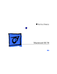
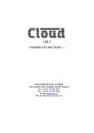
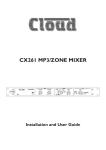
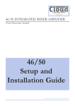
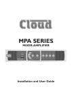
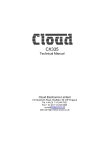
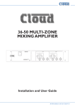
Z4II & Z8II ZONE MIXERS
Installation and User Guide
Contents
Safety Information................................... 4
Setting Up & Operation........................ 16
Safety Notes Regarding Installation.................... 4
Music Inputs......................................................... 16
Gain & level........................................................................ 16
Local/remote control....................................................... 16
Conformities.......................................................... 4
Safety Considerations and Information.............. 4
Overview................................................... 5
Introduction........................................................... 5
Scope of this manual...........................................................5
What’s in the box.................................................. 5
Main Features........................................................ 5
Optional System Components............................ 6
DM-1 Dual Microphone Input Module...........................6
LM-1 Mic/line input module with remote music
control...................................................................................6
RL-1 Remote Music Level Control..................................6
RSL-6 Remote Music Level/Source Control..................6
PM Series Paging Microphones.........................................7
PM1 Paging Microphone.....................................................7
Block Diagram....................................................... 7
Front Panel Description....................................... 8
Rear Panel Description......................................... 9
Installation.............................................. 10
Hardware Considerations.................................. 10
Power Supply....................................................... 10
Fuses and ratings............................................................... 10
System Connections........................................... 10
Music Sources.................................................................... 10
Mono and stereo sources........................................... 10
Balanced sources........................................................... 10
Zone outputs..................................................................... 11
Unbalanced inputs......................................................... 11
Microphone inputs........................................................... 12
Facility Ports...................................................................... 12
Connecting a DM-1 remote input plate.................. 12
Connecting an LM-1 remote input plate................. 12
Paging System connections............................................. 13
Connecting a PM4/8/12/16 paging mic..................... 13
Connecting a PM1 paging mic.................................... 14
Music Control................................................................... 14
Connecting an RL-1 remote control plate.............. 14
Connecting an RSL-6 remote control plate............ 15
Music Mute......................................................................... 15
Microphone Inputs.............................................. 16
Phantom Power................................................................ 16
Gain & level........................................................................ 16
EQ........................................................................................ 16
High-pass filter.................................................................. 16
Paging mic input.................................................. 16
Phantom Power................................................................ 16
Gain & level........................................................................ 17
EQ & high-pass filter........................................................ 17
Zone Outputs...................................................... 17
EQ........................................................................................ 17
Priorities.............................................................. 17
Mic 1/Mic 2 priority......................................................... 17
Paging mic priority............................................................ 17
Line 6 priority.................................................................... 17
Microphone priority over input at Facility Port........ 17
Options and Additional Information.... 18
LM-1 and DM-1 active input plates – general
considerations...................................................... 18
Connecting multiple DM-1s........................................... 18
Using the Facility Ports as auxiliary zone inputs....... 19
RL-1 and RSL-6 remote control plates – general
considerations...................................................... 19
Control of music source and level via external DC.19
Music level...................................................................... 19
Music source.................................................................. 20
Fitting Bose® Series II EQ cards....................... 20
Appendix................................................. 22
Application example........................................... 22
PCB jumper location and settings..................... 23
PSU capability and optional device current
consumption........................................................ 25
Ground loops....................................................... 25
EMC considerations............................................ 25
Technical Specifications......................... 26
General Specifications........................................ 26
Notes....................................................... 27
Z4II & Z8II Installation and User Manual v1.0
3
Safety Information
Safety Notes Regarding Installation
•• Do not expose the unit to water or moisture.
•• Do not expose the unit to naked flames.
•• Do not block or restrict any air vent.
•• Do not operate the unit in ambient temperatures above
35 °C.
•• Do not touch any part or terminal carrying the
hazardous live symbol (
the unit.
) while power is supplied to
•• Do not perform any internal adjustments unless you
are qualified to do so and fully understand the hazards
associated with mains-operated equipment.
•• The unit has no user-serviceable parts. Refer servicing
to qualified service personnel.
•• If the moulded plug is cut off the AC power lead for
any reason, the discarded plug is a potential hazard and
should be disposed of in a responsible manner.
Conformities
This product conforms to the following European EMC
Standards:
BS EN 55103-1:1997
BS EN 55103-2:1997
This product has been tested for use in commercial and
light industrial environments. If the unit is used in controlled
EMC environments, the urban outdoors, heavy industrial
environments or close to railways, transmitters, overhead
power lines, etc., the performance of the unit may be
degraded.
The product conforms to the following European electrical
safety standard:
BS EN 60065:2002
The Z4II and Z8II were developed and manufactured with
high quality materials and components, which can be
recycled and/or reused.
4
Z4II & Z8II Installation and User Manual v1.0
Safety Considerations and Information
The Z4II and Z8II must be earthed. Ensure that the mains
power supply provides an effective earth connection using a
three-wire termination.
Caution - High Voltages
Do not touch any part or terminal carrying the hazardous
live symbol (
) while power is supplied to the unit.
Terminals to which the hazardous live symbol refers require
installation by a qualified person.
Caution - Mains Fuse
The internal PSU contains no user-replaceable fuses. Mains
over-current protection is provided by the fuse in the IEC
receptacle; only replace this fuse with one of an identical
type and rating.
Caution - Servicing
The unit contains no user-serviceable parts. Refer servicing
to qualified service personnel. Do not perform servicing
unless you are qualified to do so.
Disconnect the power cable from the unit before removing
the top panel and do not make any internal adjustments with
the unit switched on.
Only reassemble the unit using bolts/screws identical to the
original parts.
Overview
Introduction
What’s in the box
Thank you for purchasing this Cloud Zone Mixer. We are
confident that you will be pleased with its performance,
features, flexibility and reliability.
Unpack the Z8II or Z4II and its accessories with care. It is
always a good idea to store all packaging (if practical), in case
you ever need to return the unit to your Cloud dealer for
any reason.
The Cloud Z4II and Z8II are versatile analogue multizone
audio mixers. They are intended to form part of permanent
sound systems in pubs, bars, restaurants, hotels, offices,
factories and other areas, where multiple audio sources
(background music, TV sound, etc.) are in use and need to
be easily combined with announcements and/or paging in
one or more zones. They have been designed to interface
directly with industry-standard paging mic interfaces, and are
compatible with Cloud PM Series paging microphones.
Scope of this manual
This manual provides a comprehensive guide to the features
and functionality of the Cloud Z4II and Z8II Zone Mixers.
The two models are identical in facilities and features, and
differ only in the number of zones they support:
Model Z4II – four output zones
Model Z8II – eight output zones
As well as this manual, the shipping carton should contain
the items listed below. Please contact your Cloud dealer
immediately if any of them are missing or damaged.
•• Cloud Z8II or Z4II Zone Mixer
•• IEC mains lead (AC cord) with moulded plug
appropriate to the territory
•• Set of mating connectors for all rear panel screwterminal connectors
Main Features
•• 6 stereo line inputs
•• 8 (Z8II) or 4 (Z4II) balanced mono line outputs
•• 2 microphone inputs (balanced), phantom power
selectable
•• Separate paging mic input with contact closure zone
selection
Please read through the manual to become fully acquainted
with the numerous configuration and control functions the
units offer.
The manual is arranged as follows:
•• Overview – introduction to the Zone Mixers and their
options.
•• Installation – wiring the Zone Mixers in a practical
situation.
•• Setting Up & Operation – setting the system up and
user instructions.
•• Options and Additional Information – additional
information about system options.
•• Appendix – additional technical information. Includes
technical specifications.
The Z4II/Z8II manual includes full details of the optional
LM-1 and DM-1 remote input panels. Basic information
on interfacing Cloud PM Series paging microphones and
connecting the RL-1 and RSL-6 remote control plates is also
provided. This information is also supplied with each optional
item.
•• Per-zone facility port for optional remote line and/or
mic input plates
•• Mic routing to all zones with programmable override
logic
•• Per-zone front panel control of music level, music source
and mic level
•• Supports per-zone remote control of music level and
source
•• HF & LF EQ adjustment for each mic input and for
music in each zone music output
•• Preset gain trim control for each mic and music input
•• Line input 6 may have priority over other music inputs
•• Accepts Bose® EQ cards
•• External Music Mute input for interfacing with
emergency systems
•• 3U 19” rack-mounting unit
Thank you again for placing your confidence in Cloud
products.
Z4II & Z8II Installation and User Manual v1.0
5
Optional System Components
The following components may form part of the audio
system and may be ordered separately if required. They may
also be retrofitted to a system at a later time.
control of zone music level and source. The music ducking
facility is also provided for the mic input. See page 12
(Connecting an LM-1 remote input plate) and page 18 (LM-1
and DM-1 active input plates) for more information.
RL-1 Remote Music Level Control
DM-1 Dual Microphone Input Module
4
5
RL-1
6
3
7
1
9
2
8
0
10
MUSIC LEVEL
fig.1: DM-1
The DM-1 is an active input plate which allows one or two
microphones to be connected to the Zone Mixers in a
remote location. Each microphone has its own level control,
and overall preset HF/LF EQ controls are also provided. A
Music Ducking button activates the Zone Mixer’s priority
circuitry; when enabled, a microphone signal from the DM-1
will reduce the music level in the zone where it is installed.
fig.3: RL-1
The RL-1 is a small plate with a single control for locally
adjusting the music level in a zone. It is connected to one of
the mixer’s Music Control Ports. See page 14 (Connecting an
RL-1 remote control plate) and page 19 (RL-1 and RSL-6 Remote
control plates) for more information.
RSL-6 Remote Music Level/Source Control
The DM-1 connects to one of the unit’s Facility Ports,
and the microphone signals are fed to that zone only. The
mixer’s Mic 1 and Mic 2 inputs remain available. Multiple
DM-1s (in the same zone) may be daisy-chained to provide
mic inputs in more than one position. The DM-1 fits a
standard UK-style dual-gang electrical back box. See page
12 (Connecting a DM-1 remote input plate) and page 18 (LM-1
and DM-1 active input plates) for more information.
2
3 4 5
6
1
RSL-6
SOURCE SELECT
4
5
6
7
3
2
LM-1 Mic/line input module with remote
music control
8
9
1
0
10
MUSIC LEVEL
fig.4: RSL-6
The RSL-6 is the same size as the RL-1 and connects in a
similar way; it allows local music source selection as well as
music level control. See page 15 (Connecting an RSL-6 remote
control plate) and page 19 (RL-1 and RSL-6 Remote control
plates) for more information.
fig.2: LM-1
The LM-1 resembles the DM-1, but has one microphone
and one stereo line input, which provides a convenient
access point for the connection of a DJ mixer, laptop, MP3
player or similar. The plate also includes the functions of
the RSL-6 Remote Control Plate (see below), permitting
6
Z4II & Z8II Installation and User Manual v1.0
PM Series Paging Microphones
PM1 Paging Microphone
fig.5: PM16
fig.6: PM1
Cloud PM paging microphones may be connected directly to
the Z8II and Z4II. Models are available which can page to 4, 8,
12 or 16 zones. Clearly, not all zones on the ‘higher’ models
can be addressed with only one zone mixer. See page 13
(Connecting a PM4/8/12/16 paging mic) for more information.
The Cloud PM1 paging microphone is also compatible with
the Z8II and Z4II. It is a much simpler unit which addresses
only one zone. See page 14 (Connecting a PM1 paging mic) for
more information.
Block Diagram
The simplified block diagram below illustrates the basic signal architecture of the Z8II. Only the routing and logic for one zone
output is shown. The architecture of the Z4II is identical, the only difference being the number of zone outputs.
fig.7: Z8II Block Diagram
Z4II & Z8II Installation and User Manual v1.0
7
1
10
6
7
4
9
5
3
8
10
2
fig.8: Z8II Front Panel
Note - The front panel of the Z8II is shown above.
The Z4II’s is identical, except that it only has controls for zones 1 - 4.
Front Panel Description
1
MUSIC SOURCE – 6-way rotary switch selecting
which Line Input (1 to 6) will be the music source for
each zone. See page 16 (Local/remote control)
2
MUSIC LEVEL – adjusts the music level in each
zone. See page 16 (Music Gain & Level)
3
MICROPHONE 1 – adjusts the level of the
microphone connected at Mic 1 input in each zone. See
page 16 (Microphone Inputs Gain & Level)
4
MICROPHONE 2 – adjusts the level of the
microphone connected at Mic 2 input in each zone. See
page 16 (Microphone Inputs Gain & Level)
5
PAGING MIC LEVEL – adjusts the level of the
microphone connected at the Paging Mic input in each
zone. This is a preset control and is intended to be set
on installation and not readjusted by the user. See page
17 (Paging Mic Gain & EQ)
8
Z4II & Z8II Installation and User Manual v1.0
6
POWER – latching push-button switch with integral
green LED
7
MUTE – red LED which illuminates when an external
Music Mute command is applied (i.e., from fire control
panel, etc.) See page 15 (Music Mute)
8
Zone idents – a space is provided below each zone’s
controls for printed labels identifying the zone by name
9
Source idents – a space is provided beside Zone 1’s
source select control for printed labels identifying each
music source by name
10
Rack mounting ears – the unit may be rack-mounted
in a standard 19” equipment rack. It requires 3U of rack
height. See page 10 (Hardware considerations)
10
11
3
4
13
12
5
6
7
14
8
16
1
2
9
15
fig.9: Z8II Rear Panel
Note - The rear panel of the Z8II is shown above.
The Z4II’s is identical, except that it only has output connections for zones 1 - 4.
Rear Panel Description
1
2
LINE INPUTS – 6 pairs of RCA (phono) sockets
(Line 1 to Line 6) for connection of music sources.
Inputs are stereo, summed internally to mono. See page
10 (Music sources)
LINE INPUT GAIN – preset trim control for each
input, providing ±10 dB of gain adjustment for input
level matching. See page 16 (Gain & Level)
3
MIC INPUTS – 2 balanced microphone inputs
(Mic 1 & Mic 2) on latching XLR sockets. See page 12
(Microphone inputs)
4
MIC GAIN – preset mic gain control for each input,
gain range 10 to 60 dB. See page 16 (Microphone Inputs
Gain & Level)
5
MIC EQ – HF & LF preset EQ controls. See page 16
(Microphone Inputs EQ)
6
PAGING MIC INPUT – dedicated balanced input
(XLR) for paging mic. See page 16 (Paging mic input)
7
PAGING MIC GAIN – as
Mic Gain & level)
8
PAGING MIC EQ – as
EQ & high-pass filter)
5
4
. See page 17 (Paging
9
PAGING MIC ACCESS PORT – 10-pin 5 mm-pitch
screw-terminal connector for per-zone contact closure
paging access. See page 13 (Paging system connections)
10
ZONE OUTPUTS – 8 balanced outputs* for each
zone on 3-pin 3.5 mm-pitch screw-terminal connector.
See page 11 (Zone outputs)
11
ZONE EQ – HF & LF music EQ adjustment for each
zone output. See page 17 (Zone output EQ)
12
FACILITY PORT – 9-pin female Dsub per-zone, for
connection of remote input plates and other functions.
See page 12 (Facility Ports)
13
MUSIC CONTROL PORTS – 3-pin 5 mm-pitch
screw terminal connector per-zone, for connection of
RL-1/RSL-6 remote control plates. See page 14 (Music
Control)
14
LOCAL/REMOTE SWITCHES – determine
whether front panel music source controls will remain
active when remote control plates are connected (perzone). See page 14 (Music Control)
15
MUSIC MUTE – 2-pin 5 mm-pitch screw terminal
connector for connection of external emergency muting
relay (e.g. fire control panel). See page 15 (Music Mute)
16
MAINS – Fused IEC receptacle for AC mains (includes
storage for spare fuse). See page 10 (Power Supply)
. See page 17 (Paging Mic
* Only 4 zone outputs on Model Z4II (Items 10 to 14 )
Z4II & Z8II Installation and User Manual v1.0
9
Installation
Hardware Considerations
System Connections
The Z4II and Z8II Zone Mixers are built in 3U-high 19” rack
mount enclosures. It is recommended that the Zone Mixer
is installed in a 19” rack wherever possible. The units are
approx. 160 mm deep, but 250 mm of rack depth should be
available to allow for rear connectors and cabling.
Music Sources
The Z4II and Z8II have low power consumption and there
are no thermal considerations other than ensuring that
the ventilation grilles are not obstructed once the mixer
is installed installed. The ventilation grilles are at the rear
(immediately above the AC input connector); in the bottom
panel (behind the AC mains switch), and in the side panels.
Other equipment may be installed above or below the Z4II/
Z8II within this constraint.
The choice of location will be dictated by the specifics of the
system and building layout. It is recommended that wherever
possible, the Z4II/Z8II should be mounted in an equipment
rack along with as many of the music sources (CD players,
music servers, TV receiver boxes, etc.) and audio power
amplifiers (driving the zone loudspeakers) as practical.
When deciding the Zone Mixer’s location, bear in mind
that access to it will probably be required even if a full
complement of remote controls is being fitted as part of the
system, as some adjustments can only be made on the mixer
itself.
Power Supply
The European versions of the Z4II and Z8II operate on
standard 230 V AC mains; alternative versions are available
which operate on 115 V AC. An IEC mains cable with a plug
appropriate for each country is supplied with the European
unit. The unit’s power consumption is 20 VA (Z4II) or 28 VA
(Z8II)
Fuses and ratings
The only user-accessible fuse is an AC mains fuse in the
IEC connector housing. Only replace a fuse with one of
exactly the same type. The table below gives the correct
fuse types.
VERSION RATING
230 V
125 mA
115 V
250 mA
FUSE TYPE
20 mm x 5 mm
slo-blo T125mA
20 mm x 5 mm
slo-blo T250mA
The fuseholder may be accessed by prising the slide below
the connector open, using a small screwdriver. The holder
has an extra cavity for storing a spare fuse; note that the
“active” fuse is that in the inner cavity.
10
Z4II & Z8II Installation and User Manual v1.0
Connect the system’s various music sources to LINE 1
to LINE 6. All line inputs offer unbalanced connection for
stereo sources on a pair of standard RCA jacks (phono
sockets). The sensitivity range available should allow most
standard items of audio equipment such as CD players,
PC-based music servers, TV tuners, etc., to operate at a
satisfactory level. Most equipment of this type will have
stereo unbalanced outputs, and as long as the source
equipment is adjacent to the Zone Mixer, normal phonophono leads can be used. Always avoid using pre-made leads
of an unnecessary length.
Mono and stereo sources
The Z4II and Z8II are mono mixers; the stereo line inputs
are summed internally to mono. Stereo sources should be
connected in a normal stereo configuration, using both L
and R inputs. If connecting a mono source with only a single
output, it may be connected to either the left or the right
input.
Balanced sources
If it is necessary to connect an item of source equipment
with a balanced output to the Zone Mixer, a balancing
transformer should ideally be connected between the source
and the unbalanced input. Suitable audio transformers, which
should have a ratio of 1:1, are readily available from major
audio component suppliers. The transformer(s) should
be mounted as close to the Zone Mixer as practical, and
housed in a screened enclosure if they are not individually
screened. The preferred connection method is shown in
fig.10.
Balanced outputs (XLRs):
pin 1 ground
pin 2 hot
pin 3 cold
Audio balancing transformers
LEFT
3
1
2
-
-
+
+
SCN
SCN
LEFT
SCN
Unbalanced
inputs
SCN
Unbalanced
inputs
RIGHT
3
1
2
-
-
+
+
SCN
SCN
RIGHT
fig.10: Balanced - Unbalanced wiring using transformer
If transformers are not available, a balanced source may
feed an unbalanced input directly as long as care is taken
over how the connections are made. A variety of design
techniques are in use to implement balanced outputs in
audio equipment, and some designs require different wiring
protocols to others. Installers are advised to check the
manuals with each item for guidance on how the outputs
should be connected to an unbalanced input.
However, the wiring methods shown in fig.11 and fig.12 will
work in a large number of cases. If hum or other distortion
is found to result, try disconnecting the ‘cold’ leg of the
balanced output (pin 3 on XLRs).
When using single-core cable,
join ‘cold’ to screen at the
source
3
2
1
Unbalanced
input s
LEFT
RIGHT
+
SCN
Zone outputs
Connect the inputs of the power amplifiers feeding the
loudspeakers for each zone to ZONE 1 to 8*. Note that
the zone outputs are all mono. All outputs are balanced and
will drive input impedances down to 600 Ω. Nominal output
level is 0 dBu (775 mV). The output is designed to drive
professional/industrial power amplifiers with balanced inputs
(typically on XLRs). In this case, wire as the diagram in fig.13.
Note that the screen can be left unconnected at the source
end if earth loops are a problem.
*ZONE 1 to 4 only on Z4II.
LEFT
SCN
3
2
+
+
SCN
SCN
RIGHT
3
2
1
2
2
Unbalanced
inputs
LEFT
RIGHT
+
SCN
SCN
LEFT
3
2
-
-
+
+
SCN
RIGHT
Balanced outputs (XLRs):
pin 1 ground
pin 2 hot
pin 3 cold
fig.12: Balanced - Unbalanced input #2
SCN
SC
+
-
fig.13: Balanced connection
-
3
+
The screen connection at the
zone end may be omitted if it
helps reduce earth loops
fig.11: Balanced - Unbalanced input #1
1
1
+
Balanced outputs (XLRs):
pin 1 ground
pin 2 hot
pin 3 cold
1
Z8II/Z4II Balanced output:
pin 1 ground
pin 2 cold
pin 3 hot
SCN
1
Balanced outputs (XLRs):
pin 1 ground
3
pin 2 hot
pin 3 cold
SCN
+
When using twin-and-screen
cable, join ‘cold’ to screen at
Z8II/Z4II end
Unbalanced inputs
If audio amplifiers with only unbalanced inputs are being
used (e.g. hi-fi amplifiers), the following wiring should be
adopted:
Z8II/Z4II Balanced output:
pin 1 ground
pin 2 cold
pin 3 hot
+
3
2
1
SCN
SC
When using single-core cable,
don’t connect ‘cold’ at the
Z8II/Z4II
+
Unbalanced input (e.g. phono)
fig.14: Balanced output - Unbalanced input: using single-core screened cable
Z8II/Z4II Balanced output:
pin 1 ground
pin 2 cold
pin 3 hot
3
2
1
+
-
When using twin-and-screen
cable, don’t connect the screen
at the amplifier end.
SCN
SC
+
Unbalanced input (e.g. phono)
fig.15: Balanced output - Unbalanced input: using twin-core screened cable
Z4II & Z8II Installation and User Manual v1.0
11
Microphone inputs
Connecting a DM-1 remote input plate
Mic 1 and Mic 2 inputs are intended for the direct
connection of microphones. They are electronically balanced
and transformerless with an input impedance of greater than
2 kΩ and optimised for use with microphones of 200 to
600 Ω impedance. Unbalanced microphones may be used by
connecting pins 3 to pin 1 (cable screen) in the XLR plug. 15 V phantom power is available, see page 16 (Phantom
Power).
The DM-1 should be connected to a Facility Port using
multicore cable with an overall screen. 7 of the 9 pins are
used, so 8-core cable (readily available) is ideal.
Each mic input may be routed to any of the zones in use,
at any level in each zone. Each zone may be configured so
that any microphone announcements automatically reduce
the music level in that zone while the announcement is in
progress (see page 17 (Mic1/Mic2 Priority) for more details.)
Z4 II /Z8 II FACILITY PORT
The Paging Mic input has the same electrical characteristics
as Mic 1 and Mic 2, but is intended for the connection of
a dedicated paging microphone. Mic signals at this input
will route to all zones at a level determined by the front
panel preset Paging Level controls, ducking the music while
an announcement is in progress.VOX or contact-closure
triggering of the paging priority circuit may be selected; see
page 17(Paging mic priority) for more details.
The DM-1’s upper PCB is fitted with a 10-way screwterminal connector block, and this should be wired to the
Facility Port as shown in the diagram fig.16.
1
6
2
7
3
8
4
9
5
CABLE SCREEN
10 9 8 7 6 5 4 3 2 1
DM-1 (uppermost) PCB
Facility Ports
Each zone of the mixer is provided with a Facility Port in
the form of a rear panel 9-pin female Dsub connector. The
primary use of the Facility Port is for the connection of
DM-1 and LM-1 remote active input plates, but it may also
be used as a general-purpose, per-zone auxiliary balanced
input (see page 19 for more information on this application).
Note that audio connected via a Facility Port will only
appear at the same-numbered Zone Output, and no other.
fig.16: DM-1 Facility port
Note that the cable’s screen should be connected to
terminal 3 at the DM-1 end, and to the shell of the Dsub
connector at the mixer end. Note also that DM-1 terminals
9 and 10, and Dsub pins 1 and 2 are not used in this
connection.
The active plates operate on DC power supplied by the
mixer. The current consumed by each plate is minimal and
in the vast majority of installations there will be no power
supply issues. Nevertheless, installers are urged to check the
data in the Appendix regarding PSU capacity on page 25 (PSU
capability and optional device current consumption).
It may be useful for additional DM-1s to be installed in a
zone, to allow the connection of microphones at more
than one location within a large room, for example. See
page 18 (Connecting multiple DM-1s) for details of how to
interconnect multiple DM-1s.
The pinout of the Facility Port connector is given in the
table below:
Connecting an LM-1 remote input plate
PIN
1
2
3
4
5
6
7
8
9
USE
Remote source select
Remote level control
Balanced audio input hot
(+)
Balanced audio input cold
(-)
Noise Gate control
-15 Vdc
+15 Vdc
0 Vdc
VCA control voltage
Please also refer to page 18 (LM-1 and DM-1 active input
plates – general considerations) for further information
regarding installation of remote active input plates.
12
Z4II & Z8II Installation and User Manual v1.0
The LM-1 should be connected to a Facility Port using
multicore cable with an overall screen. All 9 pins are used,
so 10- or 12-core cable (readily available) is ideal. The
LM-1 includes controls for local music level and source
selection, the wiring for these functions being catered for
on the Facility Port. Thus it is not necessary to make any
connections to the Zone’s Music Control Port.
The LM-1’s upper PCB is fitted with a 10-way screwterminal connector block, and this should be wired to the
Facility Port as shown in the diagram fig.17.
(either by a local PSU or via the CDPM digital network from
another PM unit).
Z4 II /Z8 II FACILITY PORT
1
6
2
7
3
PM8 PAGING MICROPHONE
8
4
TERM1
9
TERM2
TERM8
5
+V
0V
Z1
Z2
Z3
Z4
Z5
Z6
Z7
Z8
Z1
Z2
Z3
Z4
Z5
Z6
Z7
Z8
HOT COLD GND
CABLE SCREEN
10 9 8 7 6 5 4 3 2 1
LM-1 (uppermost) PCB
fig.17: LM-1 Facility port
Note that the cable’s screen should be connected to
terminal 3 at the DM-1 end, and to the shell of the Dsub
connector at the mixer end.
Before the LM-1’s music source and level controls will
operate, the LOCAL/REMOTE push-button switch ( 14 on
page 9 - Rear Panel Description) to REMOTE (i.e., pressing
it in). In this setting, the zone’s front panel Music Level and
Source Select controls become inoperative.
This connection only required if
the PM Series microphone is to
be powered from the mixer
0V
+V
ZONE ACCESS
HOT COLD GND
PAGING MIC INPUT
Z8II MIXER
Paging System connections
Cloud PM Series paging microphones may be connected
directly to the Z4II and Z8II.
Two connections are required: the paging mic audio signal
should be connected to the Paging Mic Input ( 6 on page
9- Rear Panel Description) and the control cable to the Zone
Access port ( 9 on page 9).
fig.18: PM8 - Z8II wiring connections
For individual zone paging as described above, the paging
mic priority trigger should be selected to ‘SW’ by moving J5
on each zone sub-board. See page 17 (Paging mic priority) for
further information.
Connecting a PM4/8/12/16 paging mic
These microphones are equipped with both digital and
analogue paging interfaces; the Z4II and Z8II use the
analogue interface. PM microphones are available in 4, 8,
12 or 16-zone versions; the installer should be sure he/she
understands how paging zones correspond to mixer zones
before commencing wiring.
Standard two-core screened audio cable may be used for
the audio signal, and stranded multicore cable with an
overall screen for the control cable. The number of cores
required in the latter will be determined by the model of PM
microphone being used and whether the mixer is a Z4II or
Z8II; however, note that one additional core will be required
if the PM Series microphone is to be powered from the
Zone Mixer.
Connections on the PM microphone are made via the
rear cable access glands and screw terminal blocks on
the internal PCB (TERM1, TERM4 and TERM8 in this
case). Full connection details and notes on power supply
considerations can be found in the PM Series Installation and
User Guide.
fig.18 shows both the cable connections between a PM8 and
a Z8II. Note that DC power supply connection will not be
required if the PM microphone is powered independently
Z4II & Z8II Installation and User Manual v1.0
13
Connecting a PM1 paging mic
Music Control
The PM 1 is a simple, passive paging microphone suitable for
situations where announcements are always made to the
same zone(s). It can be connected directly to Z8II/Z4II zone
mixers, the control cable being wired to the pin(s) of the
Zone Access port corresponding to the zone(s) in which
announcements are required. Any or all of the zones may be
paralleled if multiple zones need to operate from the PM1.
An alternative method for achieving paging to all zones is
to ignore the control cable altogether and set the paging
priority trigger for all zones to VOX. By doing so, it is the
presence of an audio signal from the mic itself that triggers
the priority circuitry. See page 17 (Paging mic priority) for
further information.
Like many other Cloud products, the Z8II and Z4II allow
remote control of music level and source selection in each
zone. The Cloud remote control plates models RL-1 (music
level only) and RSL-6 (music level and source selection)
provide an elegant solution, though control via a DC voltage
from third-party systems is also possible (see page 19 Control of music source and level via DC).
Either a single 2-pair individually-screened cable may be
used (this gives the neatest finish), or two separate standard
microphone cables. Full connection details can be found
in the PM1 Installation and User Guide. Note that the PM1
does not require DC power.
Connections on the PM1 are made via the rear cable gland
in the base and the screw terminal blocks on the internal
PCB (U2 and U3). Full connection details can be found in the
PM1 Installation and User Guide.
fig.19 below shows the connections between a PM1 and
a Z8II. Use of 2-pair cable is assumed; the same wiring
principle is adopted if separate cables are being used for
audio and control.
Both types of plate connect via the Music Control Port
for the relevant zone (see 13 on page 9 - Rear Panel
Description). This connector is a 3-pin 5 mm-pitch screw
terminal type. Please refer to page 19 (RL-1 & RSL-6 remote
control plates) for additional information regarding cable
lengths, etc.
Connecting an RL-1 remote control plate
Wire the remote control plate as shown below. Either
single-core screened or twin-and-screen cable may be used;
in the case of the latter, ignore one of the cores. Maximum
reliable cable run is 100 m.
REMOTE LEVEL CONTROL WIRING
REMOTE MUSIC
CONTROL
PORT
RL-1
1
1
Z8 II
PAGING MIC INPUT
2
2
2
3
3
ZONE ACCESS CONNECTOR
1
3
0V
Z1
Z2
Z3
Z4
Z5
Z6
Z7
Z8
+V
SINGLE-CORE SCREENED CABLE MAY BE USED
CONNECT TO
ZONE(S) IN USE
fig.19: RL-1 control wiring
SCN COLD HOT
U2 AUDIO
N/O
PM1
N/C
GND
U3 ACCESS
fig.19: PM1 - Z8II wiring connections
14
Z4II & Z8II Installation and User Manual v1.0
Before the RL-1 will operate, the zone’s Music Control Port
must be enabled by setting the adjacent push-button switch
( 14 on page 9 - Rear Panel Description) to REMOTE (i.e.,
pressing it in). In this setting, the zone’s front panel Music
Level and Source Select controls become inoperative. As
music source selection will still be required from the mixer’s
front panel when an RL-1 is in use, the REMOTE setting
may be overridden for the source selection control only by
moving internal jumper J1 on the sub-board for the zone in
question. See page 23 (PCB Jumper location and settings) for
location of internal jumpers.
Connecting an RSL-6 remote control plate
Wire the remote control plate as shown below. Twin-andscreen cable should be used. Maximum reliable cable run is
100 m.
MUSIC MUTE
INPUT
1
REMOTE SOURCE & LEVEL CONTROL WIRING
2
3
REMOTE MUSIC
CONTROL
PORT
RSL-6
1
2
RELAY
1
2
3
NORMALLY OPEN (NO)
CONNECTION
USE TWO-CORE SCREENED CABLE
fig.21: Music mute, normally open
MUSIC MUTE
INPUT
fig.20: RL-6 control wiring
1
2
RELAY
Before the RSL-6 will operate, the zone’s Music Control
Port must be enabled by setting the adjacent push-button
switch ( 14 on page 9 - Rear Panel Description) to REMOTE
(i.e., pressing it in). In this setting, the zone’s front panel
Music Level and Source Select controls become inoperative.
Music Mute
External muting of music is available at the MUSIC MUTE
connector. National or Local Authority regulations
governing such systems may require that normal
programme material (i.e., music) should be muted in an
emergency, to ensure that any emergency messages are
clearly audible.
NORMALLY CLOSED (NC)
CONNECTION
fig.22: Music mute, normally closed
The Music Mute input is on a 2-pin 5 mm-pitch
screw-terminal connector. It should be connected to
the appropriate alarm output on whichever building
management system registers the alarm (typically the Fire
System). The alarm output must be volt-free; if no such
output is available, an intermediate relay or other isolation
device must be installed between the alarm output and the
Music Mute input.
The Mute input can be set to operate on either normally
open (NO) or normally closed (NC) contacts via an
internal jumper (see page 23 - PCB Jumper location and
settings). The factory default setting is NO, thus requiring
a short-circuit to be applied across the two pins of the
connector for muting to occur.
Visual indication of muting being activated is given by the
Music Mute LED on the front panel.
Z4II & Z8II Installation and User Manual v1.0
15
Setting Up & Operation
Music Inputs
Microphone Inputs
Gain & level
Phantom Power
To avoid dramatic changes in volume when switching
between sources, the Z8II/Z4II’s music inputs are provided
with preset gain trim controls ( 2 on page 9 - Rear Panel
Description). These vary the input sensitivity from -12 dBu
(195 mV) to +8 dBu (2.0 V). When setting the system up,
play audio from all the sources in use and listen to them
one at a time in a convenient zone (preferably that in
which the mixer is located) at a reasonable volume. Taking
a source of “average” volume as the reference, the gain
controls of the others should be adjusted so that there is
no appreciable difference in volume between any of the
sources. (With a typical CD player as the source, setting
the gain on its channel to mid-way is a good starting point.)
Note that consideration may need to be given to the type of
programme in use, particularly if one or more sources are
TV sound.
Each microphone input (MIC 1 & MIC 2) has 15 V phantom
power available. This will be adequate to power a wide range
of condenser microphones. (Some “studio quality” mics may
require a higher phantom voltage and thus necessitate an
external PSU). To enable phantom power at the mic inputs,
internal motherboard jumpers J1 (MIC 1) and/or J2 (MIC
2) should be moved to their ON positions. See page 23 for
jumper locations. Phantom power should NOT be enabled if
dynamic microphones are to be used.
In normal operation, the music level in each zone is set with
the Music Level control on the front panel ( 2 on page
8 - Front Panel Description). This control will not be operative
if the corresponding rear panel LOCAL/REMOTE pushbutton is set to REMOTE. When setting the audio system
up, set the gain controls (if any) on the power amplifiers for
each zone to minimum, then turn the Music Level control
on the mixer to maximum. Then increase the zone volume
by turning up the power amplifier gain until it is as loud as
will be required in normal use. This method ensures that
excessive volumes will not be possible with the mixer’s
operational controls.
Note that the setting of the music level has no effect on
microphone or paging volume.
Local/remote control
If a zone has an RL-1 or RSL-6 remote control plate or an
LM-1 line input plate connected, the rear panel LOCAL/
REMOTE push-button must be set to REMOTE (button
in) for the remote controls to be operative and for the
corresponding front panel controls to be disabled. Zones
without such plates should be set to LOCAL (button out).
The setting of the internal PCB jumper J1 on each zone
sub-board is also relevant. The default setting is SW. This
means that zone music source selection will be determined
by the rear panel switch setting; the front panel control in
LOCAL and via a remote plate or other external control
in REMOTE. If the jumper is set to FR, the source selection
will always be made with the front panel control whatever
is connected at the rear panel or the setting of the LOCAL/
REMOTE switch. If external control of music level only (i.e.,
not source selection) is required, J1 should be set to FR and
the LOCAL/REMOTE switch to REMOTE.
16
Z4II & Z8II Installation and User Manual v1.0
Gain & level
Each main microphone input (MIC 1 & MIC 2) is provided
with a rear panel preset gain control ( 4 on page 9). A wide
range of gain is available and there should be no problem in
obtaining a satisfactory level from any normal microphone.
The mic gain control should be adjusted by speaking
normally into a microphone of the correct type. Turn the
front panel Mic Level control up to maximum and listen in
a convenient zone; the rear panel gain control should be
carefully advanced until the mic volume is as loud as it is
ever likely to be needed, and then reduced slightly. There
should be no audible distortion. The use to which the
microphone is to be put should be borne in mind – karaoke
is more likely to overload the mic preamplifier than spoken
announcements, if the gain is not set correctly.
In normal operation, the mic level in each zone is set with
the Mic Level controls on the front panel ( 3 & 4 on page
8).
EQ
Each mic input has associated HF and LF EQ controls ( 5
on page 8) These provide 10 dB of cut or boost at 5 kHz
and 100 Hz respectively and should be adjusted by listening
to achieve a clear mic sound. Again, the application should be
borne in mind when making adjustments.
High-pass filter
Each mic input has a fixed 100 Hz high-pass filter to remove
the lowest frequencies. This helps to reduce the effects of
breath blasts and microphone handling noise. The filter is
always in circuit.
Paging mic input
Phantom Power
The paging mic input also has 15 V phantom power available.
This will NOT be required if a Cloud paging microphone is
being used with the mixer, but may be necessary with other
manufacturers’ equipment. It is enabled by moving internal
motherboard jumper J3 to its ON positions. See page 23 for
jumper locations.
Gain & level
The paging mic input has a rear panel preset gain control
( 7 on page 9). A wide range of gain is available and there
should be no problem in obtaining a satisfactory level from
most paging microphones.
The mic gain control should be adjusted by making an
announcement. Set the front panel Paging Mic Level preset
control at about halfway and listen in a convenient zone; the
rear panel gain control should be carefully advanced until
the announcement is heard clearly and without distortion.
If possible, the person who will normally make paging
announcements should speak when making this adjustment.
Following the setting of the paging mic gain, the paging level
in all the other zones should be set, by listening in each zone,
with the Paging Mic Level controls on the front panel ( 5
on page 8).
EQ & high-pass filter
The paging mic input has associated HF and LF EQ controls
( 8 on page 9 - Rear Panel Description) These are identical to
the MIC1 & 2 EQ controls and should be adjusted similarly.
A 100Hz fixed filter is also included in the circuitry, as with
the other mic inputs.
Zone Outputs
In normal operation, the music level in each zone will
be set by the front panel Music Level control, or by a
corresponding control on a remote plate. Follow the
procedure described in Music Inputs - Gain & level (page 16)
to adjust the music level in each zone.
EQ
The various zones in a building often have different
acoustic properties, and may also have different models
of loudspeaker installed. The Z4II and Z8II are fitted with
HF and LF EQ adjustments ( 11 on page 9) for the music
signal at each zone output to enable the audio frequency
response to be best matched to each zone. The controls
should be adjusted by listening; up to 10 dB of cut or boost
at 10 kHz (HF) and 50 Hz (LF) is available. Note that these
EQ adjustments do not affect the frequency response of
microphones or paging.
Priorities
The Z4II and Z8II offer several options for determining what
happens to music signals when announcements are made.
The options are selected via internal jumpers, and should
be set to suit the requirements of the installation when the
system is installed. See page 23 for location of the internal
jumpers.
Mic 1/Mic 2 priority
By default, fully automatic, voice operated priority
is provided for the microphone inputs. When either
microphone is used, all music signals will attenuate by
approximately 30 dB; after the announcement, the music
signals will restore smoothly to their former level, over a
period of 3, 6 or 12 seconds.
The Mic 1/Mic 2 priority over music can be disabled on a
per-zone basis by setting J6 on the relevant zone sub-board
to the ‘OFF’ position. The release time may also be set on
a per-zone basis to 3S or 6S by moving J3, or to 12S by
removing J3 altogether. Note that the release time setting
will apply to all music ducking, regardless of which priority
setting initiates it.
Paging mic priority
When an announcement is made via the paging mic input,
it has full priority over both the music signals and any
microphones in use via Mic 1 and Mic 2 inputs. This is a fixed
priority, and cannot be overridden.
The paging mic priority can be triggered either by voice
detection or by the grounding of the access contact; the
sub-board jumper J5 can be set to ‘VOX’ for voice triggering
(the default) or set to ‘SW’ for access contact triggering. If
PM Series multi-zone paging microphones form part of the
system, J5 should be set to ‘SW’.
When multiple PM Series paging microphones are in use, it
is possible for one to have a priority over the others. This
is a function of the microphones, not of the mixer; please
consult the PM Series User and Guide for more information.
Line 6 priority
It may sometimes be necessary for one music input to have
priority over all the others; for example, a jukebox in a bar,
or a digital sound store programmed to make automatic
announcements in a public space. Line input 6 may be set
to have priority in any or all zones over whichever source
is selected for the zone by its Music Source control. This
priority is set by moving jumper J2 to the ‘ON’ position on
as many zone sub-boards as required. (The default setting is
‘OFF’.)
When the priority is selected, a signal present at Line 6
will force the zone’s source selection to that input; when
the signal disappears, the previously-selected source will be
restored over the time constant selected by J3.
Microphone priority over input at Facility
Port
If an LM-1 or DM-1 remote input plate is in use in a zone, it
is possible to give any microphone connected at the mixer
itself (i.e., Mic 1, Mic 2 or a paging mic) priority over input
sources connected at the plate. This might be desirable
in function rooms, for example, where building-wide
announcements may need to to interrupt any local use.
This priority is set by J4 on the zone sub-board. The
default setting is ‘OFF’; in this position microphones or
other sources connected at remote input plates will be
autonomous and will not be overridden by announcements
made via the mixer’s mic inputs. Setting J4 to ‘ON’ will give
Mic 1, Mic 2 and the paging mic inputs priority.
Note that this priority is independent of the music ducking
function which can be selected on the remote plates.
Z4II & Z8II Installation and User Manual v1.0
17
Options and Additional Information
LM-1 and DM-1 active input
plates – general considerations
Cloud DM-1 and LM-1 remote input plates are the same
physical size as a double-gang UK electrical socket and can
be mounted in the recessed back box provided or in a
standard surface-mounting box of 35 mm depth.
The modules should be connected to the facility input
of the relevant zone using multi-core screened cable as
described at page 12 (Connecting a DM-1 remote input plate
and Connecting an LM-1 remote input plate). The module
terminations are conventional screw terminals and the
Facility Port on the mixer is a 9-pin Dsub type connector. A
suitable mating connector is provided.
Great care must be taken when terminating the active input
plates; power is derived from the mixer and wiring errors
may cause failure of the mixer. Please check all wiring before
testing the system.
IMPORTANT: Please refer to page 25 (PSU capability and
optional device current consumption) for information regarding
current draw and power supply capability.
Connecting multiple DM-1s
It may be desirable to connect local microphones at more
than one location in a zone (in a large function room, for
example). DM-1 dual microphone input plates may be “daisychained” to achieve this. All DM-1s thus wired will, of course,
only be available to the zone to whose Facility Port the chain
is connected.
Multiple DM-1s are wired as shown in fig.23. Six
interconnections are used, including a cable screen; it will
generally be convenient to use the same cable type as that
between the mixer and the first DM-1 in the chain, the extra
cores being ignored.
Z4 II /Z8 II FACILITY PORT
1
6
2
7
3
8
4
9
5
CABLE SCREEN
10 9 8 7 6 5 4 3 2 1
First DM-1 - (uppermost PCB)
10 9 8 7 6 5 4 3 2 1
Second DM-1 - (uppermost PCB)
fig.23: Connecting multiple DM-1plates
Remember to consider the current drawn by any additional
input plates – see page 25 for details of current consumption
and PSU capability.
18
Z4II & Z8II Installation and User Manual v1.0
Using the Facility Ports as auxiliary zone
inputs
PIN
The Facility Port provides a balanced audio input. If a port is
not connected to DM-1 or LM-1 remote input plates, it may
be used as a direct input to the zone from other equipment
forming part of the system (for example, a permanently
installed DJ mixer which only ever needs to feed its output
to that particular zone.)
USE
1
2
0V ref.
Music level control ( 0 to +10 V)
3
Music source selection (0 to +10 V)
CONTROL
SYSTEM
Wire an external balanced source to the facility port as
shown below:
4k7
3
1
1
15k
MUSIC SOURCE
SELECT
Balanced output:
pin 1 ground
pin 2 hot
pin 3 cold
Z8II/Z4II Facility Port
+15 V
2
MUSIC VCA
6
MUSIC
CONTROL PORT
3
SOURCE CONTROL
2
LEVEL CONTROL
1
0 V REF
0V
2
7
8
4
9
5
+
SCN
SC
SCN
3
fig.25: External DC control
-
+
fig.24: Auxiliary zone input
An unbalanced source may also be connected; the use of
balancing transformers is recommended.
RL-1 and RSL-6 remote control
plates – general considerations
Cloud RL-1 and RSL-6 remote input plates are the same
physical size as a single-gang UK electrical socket and can be
mounted in a standard flush or surface-mounting box of 25 mm depth.
The plates should be connected to the Music Control port
of the relevant zone using single- or twin-core screened
cable as described at page 14 - Connecting an RL-1 remote
control plate and page 15 - Connecting an RSL-6 remote
control plate. The plate terminations are conventional screw
terminals and the Music Control port on the mixer is a 3-pin
5 mm-pitch screw terminal connector.
NOTE: If the control voltage source is not isolated from
the power earth, there is a small risk of creating a ‘ground
loop’ by linking the mixer technical ground (0 V) to the
ground (0 V) of the equipment supplying the control voltages.
To minimise this risk, we suggest that all pieces of equipment
be in close proximity, and supplied from the same power
outlet.
Music level
Music level in a zone may be varied over its full range by
applying a DC voltage of between 0 and +10 V to pin 2,
the 0 V reference being connected to Pin 1. 0 V on pin 2
corresponds to maximum level and +10 V will produce 60
dB of attenuation. The rate of attenuation is approximately
165 mV/dB.
Note that there is an internal 4k7 “pull-up” resistor between
pin 2 and the internal +15 V rail. If pin 2 is left “floating”, this
pull-up will result in full attenuation. The output impedance
of the control voltage source should be low enough to
overcome the effect of this resistor.
The remote control plates are passive and thus do not draw
any current from the mixer.
Control of music source and level via
external DC
It may be necessary in some installations to adjust the
music level and select music source in one or more zones
from an external control system (e.g., Crestron, AMX,
etc.). If the Music Control ports are not required for RL-1/
RSL-6 remote control plates, they may be used to input
DC voltages from the external system to effect these
adjustments.
Both music source selection and level can be controlled over
their full ranges with a DC voltage of 0 to +10 V. The pinout
of the Music Control port is as follows:
Z4II & Z8II Installation and User Manual v1.0
19
Music source
Music source for a zone may be controlled by applying
various DC voltages of between 0 and +10 V to pin 3, the
0 V reference being connected to pin 1. 0 V at pin 3 will
select Line input 6 and between +7.5 and +9 V will select
Line input 1. The other line inputs will be selected with
intermediate voltages. Taking pin 3 above +9 V will deselect
all inputs, making the zone effectively ‘off’ for music.
The table below lists the DC voltages required at pin 3 to
select each line input. The third column is the value of a
resistor which should be connected between pins 1 and 3
to permanently ‘force’ a zone to a particular line input.
INPUT
OFF
Line 1
Line 2
Line 3
Line 4
Line 5
Line 6
DC VOLTAGE
>+9.0 V
+7.5 V
+6.0 V
+4.5 V
+3.0 V
RESISTOR VALUE
+1.5 V
0V
1k8
short-circuit
16k
11k
6k8
3k9
Note that there is an internal 15k “pull-up” resistor
between pin 3 and the internal +15 V rail. If pin 3 is left
“floating”, this pull-up will cause ‘OFF’ to be selected. The
output impedance of the control voltage source should be
low enough to overcome the effect of this resistor.
Fitting Bose® Series II EQ cards
The Z4II and Z8II are compatible with Bose® Series II
loudspeakers; a single-channel Bose® equalisation module
may be fitted to as many Zone outputs as necessary.
Equalisation modules for the following Bose® models are
available:
•• Panaray MA12
•• Panaray 402-II, 502B and 502BEX
•• Panaray LT Series: Models 3302, 4402, 9402 and 9702
Other modules are available; please enquire.
To install equalisation modules, first remove the top cover
from the Z4II/Z8II (6 screws). The modules plug into the
white 12-pin connectors labelled CON2 on the verticallymounted sub-cards; there is one sub-card for each zone
output. Note the header connectors on the PCB have two
notches on one side only; these engage with lugs on the
equalisation module’s mating connector to ensure correct
orientation.
See the Appendix section “PCB jumper locations and
settings” page 23 for further details. Replace the top cover
with the original screws after fitting.
20
Z4II & Z8II Installation and User Manual v1.0
Z4II & Z8II Installation and User Manual v1.0
21
Appendix
Application example
The Z8II will find application in many types of premises, including shops, bars, hotels, schools, conference centres, offices, etc.
A typical example using most of the Zone Mixer’s facilities is given below.
CD PLAYER
POWER
AMPLIFIERS
AREA 1
FREEVIEW
RECIEVER
INPUT 1
INPUT 2
RADIO
TUNER
RSL-6
INPUT 3
INPUT 4
ZONE 1
INPUT 5
ZONE 2
INPUT 6
ZONE 3
OUTPUTS
PC
ZONE 4
ZONE 5
MIC 1
ZONE 6
MIC 2
ZONE 7
DM-1
AREA 2
OTHER
AREAS
ZONE 8
LOCAL
MICS
PAGING MIC
LM-1
PAGING ACCESS
ZONE 1
ZONE 2
ZONE 4
ZONE 5
ZONE 6
FACILTY PORTS
ZONE 3
ZONE 7
MUSIC CONTROL PORTS
ZONE 1
ZONE 2
ZONE 3
AREA 3
ZONE 4
ZONE 5
ZONE 6
ZONE 7
ZONE 8
ZONE 8
RL-1
PM PAGING
MICROPHONE
fig.26: Example application
The diagram depicts a system where four possible music (or other audio) sources are made available to three or more zones
(areas). Only three are shown for clarity. Points to note:
•• Area 1 and Area 3 have remote control plates installed: an RSL-6 (music level and source) in Area 1 and an RL-1 (music
level only) in Area 3. These are wired to the Music Control Ports for their respective zone outputs.
•• Area 1 also includes a DM-1 dual mic input plate, permitting microphones to be plugged in locally for PA purposes in that
area. This is wired to Zone 1’s Facility Port.
•• Area 2 includes an LM-1 mic/line input plate, wired to Zone 2’s Facility Port. This would allow both a microphone and a
portable stereo music source to be connected in that area. The LM-1 also provides music source and level control; note
that the LM-1 does not require a second connection to the Music Control Port to enable this.
•• Area 3 has a Cloud PM paging microphone, which would be used to originate voice messages to any of the other areas.
The paging level to Area 3 (if required) would be adjusted on installation to be at a level that does not cause feedback.
22
Z4II & Z8II Installation and User Manual v1.0
PCB jumper location and settings
The Z4II and Z8II have various internal jumpers, the setting of which may require alteration during installation. Note that there
are jumpers on both the motherboard and the individual zone sub-cards. The table below lists each jumper and its purpose,
together with the factory default setting. Note that options selectable by jumpers on the zone sub-board are per-zone, and
will need to be set on as many zone sub-boards as necessary.
JUMPER
J1
NAME
J4
MIC 1
phantom power
MIC 2
phantom power
Paging Mic phantom
power
Music Mute NO/NC
J1
Music source selection
J2
Line 6 priority
J3
Music ducking release
time
J4
Mic priority over facility
input
J5
Paging mic priority trigger
MIC 1/MIC 2 priority
J2
J3
J6
EFFECT
MOTHERBOARD JUMPERS
OFF: MIC 1 phantom power OFF
ON: MIC 1 phantom power ON
OFF: MIC 2 phantom power OFF
ON: MIC 2 phantom power ON
OFF: Paging mic phantom power OFF
ON: Paging mic phantom power ON
N/O: Contact closure required for muting
N/C: Contact opening required for muting
ZONE SUB-BOARD JUMPERS
SW: Follows rear panel switch
FR: Always via front panel only
OFF: No priority
ON: Line 6 has VOX-triggered priority over other sources
3S: 3 seconds. release time
6S: 6 seconds release time
ABSENT: 12 seconds release time
OFF: No priority
ON: MIC 1, 2 & paging mic have VOX-triggered priority over
signals at facility port
VOX: Paging mic signal triggers priority
SW: Contact closure at Access Port enables paging mic priority
OFF: No priority – mics mix with music
ON: Music ducks when mics in use
DEFAULT
OFF
OFF
OFF
N/O
SW
OFF
3S
OFF
VOX
OFF
The diagram below shows the locations of the internal jumpers (not to scale) on each of the board types. The jumpers have
two possible positions; the black square in the symbol indicates the default setting. If any jumpers need to be changed, turn
the Zone Mixer off and disconnect it from the mains. Undo the 6 screws securing the top cover of the unit and remove it.
Use a pair of small pliers to gently remove the jumpers from the PCB headers and reposition them. The jumpers on the zone
sub-boards are readily accessible from above; those on the motherboard will require long-nosed pliers. Refix the top cover
using the original screws.
fig. 27 and fig.28 give the locations of all the jumpers and of the socket for the optional Bose® EQ cards.
Z4II & Z8II Installation and User Manual v1.0
23
ZONE 1
ZONE 2
ZONE 3
ZONE 4
ZONE 5*
ZONE 6*
ZONE 7*
ZONE 8*
FRONT OF UNIT
J2
J1
J3
ZONE SUB-CARDS
J4
MOTHERBOARD (at bottom of chassis)
* Z8 II ONLY
POWER TRANSFORMER
KEY:
Jumper with two possible positions; black
square indicates factory default setting.
fig.27: Jumper locations
J6
J3
J2
(COMPONENT SIDE)
fig.28: Sub-card jumper locations
24
Z4II & Z8II Installation and User Manual v1.0
J5
J4
J1
SOCKET FOR
OPTIONAL BOSE® EQ CARD
PSU capability and optional device current consumption
In addition to supplying the Zone Mixer’s circuitry, the
internal PSU has the capacity to power some additional
items which may form part of a complete system. These
include LM-1 and DM-1 active remote input plates (via the
Facility Port), Bose® EQ cards (fitted internally), and possibly
a PM Series paging microphone (powered via the Access
Port).
The maximum current capacity of the PSU available for
powering external items is 120 mA (Z4II) or 190 mA (Z8II).
Current consumption of the various items is listed in the
table below.
ITEM
DM-1 dual mic input plate
LM-1 mic/line input plate
PM-4 or PM-8 paging
microphones
Bose® EQ for MA12, 402-II,
502B, 502BEX
Bose® EQ for 3302, 4402,
9402, 9702
EMC considerations
The Cloud Z4II & Z8II fully conform to the relevant
electromagnetic compatibility (EMC) standards and
are technically well behaved; you should experience no
operational problems and under normal circumstances, no
special precautions need to be taken. If the unit is to be used
in close proximity to potential sources of HF disturbance
such as high power communications transmitters, radar
stations and the like, the performance of the mixer may be
reduced; we suggest that the microphone cable screen be
connected to the shell of the XLR type connector and the
line input leads are kept as short as possible.
CURRENT PER UNIT
18 mA
12 mA
40 mA
12 mA
17 mA
The installer should ensure that the total current drawn by
all the external items in a system does not exceed 120 mA
(Z4II) or 190 mA (Z8II).
Note that PSU performance will be degraded at ambient
temperatures in excess of 35°C.
Ground loops
If, despite your best efforts, the completed sound system
‘hums’, you probably have a ‘ground loop’. The offending
signal source can often be identified by setting the volume
control to minimum. then disconnecting the input leads
(both left & right channels) on each line input until the ‘hum’
disappears. This problem is often caused by terminating
a screened input cable into a signal source positioned a
significant distance from the mixer. A good way of avoiding
this potential problem is to use signal sources (CD players
and the like) that are double insulated with no connection
to the mains supply earth. If a signal feed were derived from
a second mixer (a club or microphone mixer for example) it
would be perfectly normal to expect this to be earthed; we
suggest that a transformer be used to isolate the signal and
prevent a noisy loop (see page 10 - Music Sources).
Z4II & Z8II Installation and User Manual v1.0
25
Technical Specifications
Z4II & Z8II
Line Inputs
Frequency Response
Distortion
Sensitivity
Input Gain Control
Input Impedance
Headroom
Noise
20 Hz - 20 kHz, ±0.5 dB
<0.05% 20 Hz - 20 kHz
195 mV (-12 dBu) to 2.0 V (+8 dBu)
20 dB range
47 kΩ
>20 dB
-90 dB A-weighted (0 dB gain)
Microphone Inputs
Frequency Response
Distortion
Gain Range
Input Impedance
Phantom power
Headroom
Noise
Equalisation
100 Hz / -3 dB (filter) 20 kHz ±0.5 dB
<0.05% 20 Hz – 20 kHz
10 dB – 50 dB
>2 kΩ (balanced)
+15 V (PCB jumper for on/off)
>20 dB
-120 dB EIN 22 Hz - 22 kHz (150 Ω)
HF: ±10 dB @ 5 kHz, LF: ±10 dB @ 100 Hz
Facility Input
Input Impedance
Sensitivity
Noise Gate
10 kΩ (balanced); pin 3 (+), pin 4 (-)
0 dBu (775mV)
Ground pin 5 to open
Outputs
Balanced Zone Outputs
Minimum load impedance
Maximum output level
Music Equalisation
775 mV (0 dBu), 3 pin screw terminal connector
600 Ω
+20 dBu (7.75 V)
HF: ±10 dB @ 10kHz, LF: ±10 dB @ 50 Hz
General Specifications
Power Input
Fuse Rating
Fuse Type
Dimensions (W x H x D)
Weight
26
Z4II
Z8II
230 V ±10% 115 V ±10% AC 50 - 60 Hz
230 V – T100mA H
230 V – T125mA H
115 V – T200mA H
115 V – T250mA H
20 mm x 5 mm 250 V
482.6 mm x 132.5 mm (3U) x 160.0 mm
3.83 kg net
4.40 kg net
Z4II & Z8II Installation and User Manual v1.0
Notes
Bose® is a registered trademark of The Bose Corporation.
In the interest of continuing improvements Cloud Electronics Limited reserves
the right to alter specifications without prior notice.
Z4II & Z8II Installation and User Manual v1.0
27
Cloud Electronics Limited
140 Staniforth Road
Sheffield S9 3HF
England
Tel: +44 (0)114 244 7051
Fax: +44 (0)114 242 5462
email: [email protected]
web: www.cloud.co.uk